EP2314151B1 - Cisailles destinées à couper des branches - Google Patents
Cisailles destinées à couper des branches Download PDFInfo
- Publication number
- EP2314151B1 EP2314151B1 EP10196294.2A EP10196294A EP2314151B1 EP 2314151 B1 EP2314151 B1 EP 2314151B1 EP 10196294 A EP10196294 A EP 10196294A EP 2314151 B1 EP2314151 B1 EP 2314151B1
- Authority
- EP
- European Patent Office
- Prior art keywords
- pulling
- roller
- shears according
- transmission
- traction
- Prior art date
- Legal status (The legal status is an assumption and is not a legal conclusion. Google has not performed a legal analysis and makes no representation as to the accuracy of the status listed.)
- Active
Links
Images


Classifications
-
- A—HUMAN NECESSITIES
- A01—AGRICULTURE; FORESTRY; ANIMAL HUSBANDRY; HUNTING; TRAPPING; FISHING
- A01G—HORTICULTURE; CULTIVATION OF VEGETABLES, FLOWERS, RICE, FRUIT, VINES, HOPS OR SEAWEED; FORESTRY; WATERING
- A01G3/00—Cutting implements specially adapted for horticultural purposes; Delimbing standing trees
- A01G3/02—Secateurs; Flower or fruit shears
- A01G3/025—Secateurs; Flower or fruit shears having elongated or extended handles
- A01G3/0255—Tree pruners, i.e. pruning shears carried at the end of a pole
Definitions
- the invention relates to a pair of scissors for cutting branches with at least two correspondingly formed, relatively movable scissor parts, of which at least one is connected to a handle device and of which at least one is acted upon by an at least partially flexible traction means with an actuating force, wherein the traction means on a Switzerlandstoffrolle is connected to the shearing part.
- the EP 0 895 712 B1 describes a pair of scissors in which a first scissor member is formed as a jaw attached to a handle portion, while a second scissor member designed as a cutting blade is pivotally connected to the jaw.
- a traction roller is provided on which a flexible traction cable engages, which is connected to an operating lever provided on the handle part and which is provided for transmitting an operating force applied by an operator.
- an eccentrically mounted chain roller is provided, which is at least partially looped by a pull chain.
- the pull chain is in turn connected to the cutting blade and thus allows the transmission of the introduced to the traction means and the associated chain roller operating force on the cutting blade. Due to the eccentric arrangement of the chain roller relative to the traction pulley variable power transmission is made possible, which allows adaptation to an average force profile that results when cutting branches.
- the variable power transmission allows a user a comfortable operation of the scissors for cutting branches, since despite the change in the cutting force over the cutting path a substantially constant operating force is applied.
- a device for tree cutting in which at the upper end of a rod a Scissors is attached.
- the scissors is attached via a located on a scissor arm rotary member to a located on the rod joint.
- the shearing mechanism can be operated from the end of the rod remote from the shears by means of a cable.
- the cable is attached directly to the shears part and is guided over two guide rollers there, with the first guide roller mounted on the rotary member and the second on the hinge.
- a shear comparable herewith also shows the German patent DE 949 784 C , Again, the pull cable is attached directly to the shears part and is directed there via a guide roller.
- the problem underlying the invention is to provide a pair of scissors of the type mentioned with improved handling.
- the traction means is operatively connected to the shearing part via a traction roller, wherein the traction sheave is formed by an object rotatable about an axis of rotation which is suitable for receiving a traction means provided for transmitting power by connecting the traction means in one end region to the traction sheave and the traction sheave wraps around at least in sections, and that the hinge device is at least substantially formed in a cutter housing.
- the traction means is arranged at least in sections in the region of a joint device provided between the gripping device and the associated shearing part, coaxially to a hinge axis of the articulated device.
- the hinge device is provided to allow angling of a cutting area formed by the two shearing parts relative to the handle device and thus to allow an adaptation of the shears to different cutting tasks.
- the hinge axis is aligned substantially parallel to a cutting plane determined by the shear parts. As a result, a particularly effective bending of the cutting area relative to the grip device can be realized.
- the accommodation of the hinge device in the cutter housing allows a particularly cost-effective design.
- the cutter housing is in contrast to the handle device, which may be designed substantially as a cylindrical tube, anyway provided with the for receiving the traction roller and the at least one scissor member.
- a manufacturing process for the cutting housing in particular as a plastic injection molding process, allows the formation of the The alignment of the hinge axis substantially parallel to the cutting plane a particularly effective bending is achieved in a small space, which is advantageous for use of the scissors.
- the traction element roller has a non-circular contour in a looping surface defined by the traction means.
- the traction means As Switzerlandstoffrolle all rotatable about an axis of rotation objects are referred to, which are adapted to receive a provided for a power transmission traction means.
- the term Buchrolle is not restrictive to understand, but the Werbachrolle can be designed in particular as a roller, disc, cuboid, cubes or as a combination of such geometries.
- the traction means is connected in one end region with the traction means role and wraps around the Switzerlandstoffrolle at least in sections.
- Decisive for the power transmission between traction means and Werbachrolle is caused by the non-circular contour of the belt surface variation of an effective radius.
- the effective radius is determined by the distance between an axis of rotation of the traction pulley and a separation point at which the traction means projects from the traction mechanism pulley and there is no further looping or no further contact between traction pulley and traction means.
- An out-of-round contour is present when the wrap-around surface has a contour deviating from a circular shape, and this contour can in particular be oval or polygonal.
- a wrap-around surface is spanned by radial vectors which are orthogonal to a rotational axis of the traction mechanism roller and aligned perpendicular to a central longitudinal axis of the traction mechanism.
- the effective radius forms the lever arm, which is responsible for the initiation of the actuating force on the traction element roller and thus at least partially for the power transmission of the applied by the user operating force on the scissors parts is important.
- the traction roller is formed only for an incomplete wrap by the traction means, in this case, the belt surface can be formed as Umschlingungsebene.
- the traction means role is formed for more than one wrap by the traction means, in this case, the wrap may be formed, for example, as a coiled surface.
- the effective radius can be varied in a wide range and thus enables a favorable adaptation of the variable force transmission to the cutting force profile determined essentially by a geometry of the shearing parts and the branches to be cut.
- the contour of the wrap-around surface can be embodied in particular as a polygon or sequence of straight and curved regions. It is crucial that due to the non-circular contour of the belt surface at least two different effective radii are realized on the traction means role.
- the contour of the traction roller in the belt surface on a curvature with at least two divergent radii of curvature achieves a particularly advantageous adaptation to the cutting force requirement which varies during the branch cutting operation.
- the occurrence of force jumps can be at least largely avoided, resulting in a particularly comfortable operation of the scissors can be achieved.
- a transmission device is provided between the traction roller and the shearing part.
- a transmission device enables an additional force transmission of the operating force applied by an operator between the traction mechanism roller and the shearing part for increasing a cutting force of the shearing part.
- the transmission device can be designed in particular as a transmission with a constant or varying ratio.
- the transmission device has a toothing roller attached to the toothing and a corresponding toothing on at least one scissor part.
- the toothing on the traction mechanism roller is designed as a gear segment or gear wheel mounted coaxially to a rotational axis of the traction mechanism roller.
- a gear segment or a gear on the traction roller can be transmitted to the at least one scissor member, which is equipped with a correspondingly executed teeth in a particularly advantageous manner, the rotational movement exerted by the traction means roll about the axis of rotation and an associated torque.
- the gear segment or the gear is provided with a uniform toothing, thereby ensuring a substantially continuous transmission ratio between the traction roller and the operatively connected shearing part.
- the gear segment or the gear may in particular be integrally provided on the traction roller.
- the traction roller can be designed in particular as a plastic injection molded part, as a metal injection molded part or as a powder metallurgy produced molding.
- the gear wheel is made of a metallic material and surrounded by the traction element roller designed as a plastic part in sections non-positively and / or positively, preferably encapsulated as an insert in the plastic injection molding process.
- the toothing is formed on at least one scissor part at least as a gear segment.
- the use of a gear segment formed as a toothing on the at least one scissor part is particularly useful when the scissor member is rotatably disposed relative to the second scissor member and a center of the gear segment is arranged coaxially to a rotation axis between the scissor members.
- the gear segment can be integrally formed on the at least one scissor part.
- stamping and laser cutting are suitable as a production method for the scissor part, which is designed in particular as a metal part. If particularly high demands are placed on the shears part, a production in the drop forging method or as a powder metallurgical molded part is conceivable.
- the traction means is designed as a traction cable.
- a particularly cost-effective and advantageous design of the traction device can be achieved.
- wire ropes, plastic ropes or ropes made of natural fibers and combinations thereof are used as pull ropes.
- the traction cable can be positively and / or non-positively received with an end region on the traction element.
- At one of the Switzerlandstoffrolle remote end of the pull rope be equipped with a control unit in the manner of a cable loop, which allows easy gripping by the operator. It may alternatively be connected to a control unit designed as an operating handle, which is mounted in particular pivotable and / or displaceable on the handle device.
- the cable loop or the operating handle allow the initiation of the operating force from the user to the pull rope.
- the traction means is guided substantially in an at least almost closed cavity, which is formed by the gripping device and a cutter housing associated with the cutter housing. This ensures that when the scissors are used to cut branches, the traction means does not catch on branches or thorns, which would make it more difficult to use the scissors. In addition, the risk of pinching, for example, the fingers of the operator is reduced by the leadership of the traction means in an at least almost closed cavity, so that a particularly advantageous operating safety is ensured.
- a receptacle for the Switzerlandstoffrolle and at least one scissor member is provided in the cutter housing.
- the cutting housing which can be produced in particular by plastic injection molding, has receptacles for the traction element and at least one of the shear parts.
- These recordings can be designed in particular as a stub axle or screw receptacles.
- the cutting housing may in particular be formed in two parts, wherein in each of the components corresponding receptacles for the traction element roller and at least one scissor member may be provided to a possible to ensure symmetrical loading with the operating forces and resulting reaction forces.
- the cutter housing at least one deflection device for a sectional orientation of the traction means is assigned coaxially to the hinge axis.
- the deflection device which can be designed in particular as a rotatably mounted in the cutter housing deflection roller, allows in a simple manner an orientation of the traction means coaxially to the hinge axis. As a result, a particularly low-friction transmission of the actuating force on the traction means is ensured on the traction element in the hinge axis.
- guide sections fixedly connected to the cutter housing for example slide rails, on which the traction means is deflected, as a result of which a particularly simple design of the deflecting device can be realized.
- the Switzerlandstoffrolle and the hinge axis are preferably in the cutting plane or at a small distance parallel to this.
- the axis of rotation of Switzerlandstoffrolle is aligned perpendicular to the cutting plane.
- a housing surrounding the traction mechanism roller has an extension in the direction of the axis of the traction mechanism roller, which in a preferred embodiment of the invention amounts to a maximum of 50% of the maximum housing dimension in the direction of the articulation axis.
- the maximum extension of the housing in the direction of the axis of the traction pulley is in a preferred embodiment by at most 50% greater than the diameter of a pipe serving as a stem.
- At least two gear stages are provided, which are advantageously formed by different types of transmission, wherein the first gear stage preferably a variable power transmission can realize while the second gear stage realizes a constant or variable power transmission.
- the first gear stage preferably a variable power transmission can realize while the second gear stage realizes a constant or variable power transmission.
- the first gear stage preferably a variable power transmission can realize while the second gear stage realizes a constant or variable power transmission.
- a constant or a variable power transmission can be provided, this depends in particular on the type of power transmission to the shears part. If the torque present at the traction roller is transmitted via a gear transmission, a constant gear ratio is suitable for the second gear stage. If a power transmission takes place in the second gear stage, for example via a lever gear, a variable gear ratio is easier to implement.
- the first gear stage has a transmission ratio of at least 2: 1 between dispensed and initiated operating force.
- a bandwidth of the translation variation of at least 20% preferably occurs.
- the transmission ratio is selected such that at least a doubling of the operating force transmitted by the user and transmitted by the traction means is realized in the first transmission stage.
- a diameter of the mounted on the traction pulley gear maximum 50% of the minimum effective radius of the non-round running pulley.
- it can be provided with variable force transmission that due to the non-circular contour of the traction pulley a change in the effective radius and thus the transmission ratio in the first gear stage of at least 20% occurs.
- the second gear stage has a transmission ratio of at least 2: 1 between dispensed and initiated operating force.
- at least a further doubling of the introduced operating force takes place in the second gear stage as well, so that, in combination with the first gear stage, a total of at least a quadrupling of the operating force applied by the user is realized.
- This can be achieved in an advantageous manner, a variable power transmission between an operable by the operator control panel and the at least one of the traction means via the gear means scissor member.
- the first and the second gear stage each have a transmission ratio of at least 3.5: 1 between dispensed and initiated operating force, with variable power transmission in the first gear stage, if appropriate, a bandwidth of the translation variation of at least 20% is provided.
- the transmission device allows a more than 10-fold gain of the initiated operating force.
- the variation of the operating force in the first gear stage ensures a simple design of the transmission device, since the transmission of the operating force, which has already been adapted to the varying cutting force profile, to the second gear stage can preferably take place by means of a constant gear ratio.
- the pull cable can be secured with its end facing the user to a pulley arrangement, which in from the EP 0 895 712 B1 known manner can cause a further power transmission and is preferably performed in a tube.
- a pair of scissors 1 for cutting branches has scissor parts 2 which delimit a cutting area 3 designed as a cutting plane, into which objects to be cut, in particular branches, can be received.
- a shear parts 2 As a shear parts 2, a fixed blade 4 and a pivoting blade 5 are provided which are pivotally connected to each other via a provided with a locking nut 13 connecting pin 12.
- the cutting region 3 is essentially bounded by the respective mutually facing blade portions of the fixed blade 4 and the pivoting blade 5 and describes the zone in which a relative movement of the fixed blade 4 relative to the pivoting blade 5 can take place for cutting objects.
- the relative movement the shear parts 2 to each other can be used for a cutting of clippings, especially tree branches.
- the fixed blade 4 is connected via screw 14 with a cutter housing 9, which is provided for receiving further components of the scissors and is connected to a handle device 10.
- the gripping device 10 is designed substantially as a cylindrical tube and is provided for gripping the scissors 1 during operation by a user.
- an actuating handle in particular designed as a push handle or pivot lever, which is connected to a traction means designed as a traction cable 7.
- the operating handle allows the user to initiate the actuating force on the pulling cable 7 by a linear movement, a pivoting movement or a combination thereof.
- a traction roller 6 is rotatably received on a bearing pin 15 and is connected to the pull cable 7.
- the pull cable 7 is deflected in each case substantially at right angles by means of two deflection rollers 8 and is in operative connection with the actuating handle, not shown, at an end of the handle device 10 facing away from the cutter housing 9.
- the guide rollers 8 are each rotatably mounted on journal 16 and allow a low-friction force transmission from the operating handle on the pull cable 7 on the guide roller 8.
- an at least partially cut joint device 11 which consists of a fixedly connected to the handle assembly 10, substantially T-shaped axle tube 17, a latch button 18 and a corresponding to the axle tube 17 provided on the cutter housing 9 sliding bearing 19 is constructed.
- the hinge device 11 allows pivoting of the cutter housing 9 about a hinge axis 20, wherein a pivoting range of at least +/- 30 degrees to that in the Fig. 1 shown starting position is provided.
- the traction cable 7 is guided concentrically in the region of the hinge device 11 by the deflection rollers 8 to the hinge axis 20, so that no extension or shortening of the traction cable 7 takes place during a pivoting movement of the cutter housing 9 about the hinge axis 20.
- the pivot angle of the cutter housing 9 with respect to the handle device 10 is always the same cutting area 3 guaranteed.
- one of the deflection rollers 8 is fixed in the axle tube 17, while the second guide roller 8 is mounted in the cutter housing 9.
- the traction roller 6, in the Fig. 3 is shown in more detail, has a gear 21 which is positively and non-positively attached to the traction mechanism roller and which is attached to the bearing pin 15.
- the gear 21 has a uniform, concentric with the bearing pin 15 arranged toothing.
- With the gear 21 is an integrally provided on the pivoting blade 5 gear segment 22 in a form-locking operative connection, wherein the gear segment 22 is also equipped with a uniform toothing and is arranged concentrically to the connecting pin 12.
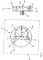
- Fig. 2 which is a sectional view of the traction mechanism roller 6 according to the Fig. 1
- one of the support cable 7 looped support area 23 in the determined by the pull rope 7 wrap which is embodied here as Umschlingungsebene 24, has a non-circular contour.
- the wrap-around plane 24 is spanned by a family of radial vectors which extend in the radial direction orthogonally from the axis of rotation 26 and respectively point perpendicular to the central longitudinal axis 27 of the pull cable 7.
- Exemplary of the radial vectors are in the Fig. 2 the effective radii R0, Rmax and R2 are shown.
- the non-circular contour of the support region 23 is chosen so that in the in Fig. 1 shown rest position of the scissors 1 as shown in the Fig. 2 the effective radius R0 at the detachment point 28, ie at the point at which the traction cable 7 protrudes in the rest position of the traction mechanism roller 6 and no further looping is present, is relatively small.
- a significantly increased effective radius Rmax is provided at the corresponding point of the traction mechanism roller 6, which merges into a smaller effective radius R2 corresponding to the cutting force decreasing again in the further cutting process ,
- the effective radius corresponds to the lever arm, with which the tensile force transmitted by traction cable 7 to the traction mechanism roller 6 is converted into a torque.
- This torque acts on the fixedly connected to the traction roller 6, uniformly shaped and concentric with the connecting pin 12 arranged gear 21 a. Since the effective radius is variable due to the non-circular contour of the support portion 23, and the initiated by the pull cable 7 actuation force is transmitted in different ways to the gear 21 and thus leads to the desired variable force transmission between the actuating handle and the pivoting blade 5, not shown.
- the cutting housing 9 has two housing halves 29a and 29b, which are joined to a parting line 30 to each other and are connected to each other with screw 14.
- the parting line 30 divides the cutter housing 9 substantially symmetrically in a housing region facing away from the scissor parts 2. In the area of the shear parts 2, however, the parting line runs as in Fig. 4 shown in detail, rearward on the fixed blade 4 along, that is, the fixed blade 4 is flat on the housing half 29b. This results in this area an asymmetrical pitch of the cutter housing 9.
- the formed by two semi-cylindrical, formed on the cutter housing parts 29a and 29b sleeve portions 31 receiving socket for the tubular gripping device 10 is divided centrally by the parting line 30.
- a concave depression 32 which is designed for a form-locking, rotationally secure reception of the grip device 10 on the cutting edge housing 9, is provided on the sleeve section 31 assigned to the cutting-edge housing part 29b.
- the outer diameter of the sleeve portions 31 is approximately 90% of a width dimension b of the cutter housing 9.
- the in the 4 and 5 handle device 10, not shown, has an outer diameter that substantially corresponds to the width dimension b of the cutter housing 9.
- the deflection roller 8 is arranged centrally in the cutter housing 9, so that the pull cable 7, which is guided by the handle device 10, can be advantageously deflected.
- the bearing pin 15 of the traction pulley 6 and the connecting pin 12 of the shear parts 2 are parallel to the plane of the 4 and 5 arranged.
- a width extension b of the cutter housing 9 in the direction of the extent of the bearing pin 15 and the connecting pin 12 is chosen to be particularly slim for advantageous handling of the scissors 1 and allows a favorable feed of the scissors. 1 even with dense branches.
- a height extent h of the cutter housing 9 in the direction of the hinge axis 20 essentially corresponds to the gap width of the scissors, as determined by an outer contour of the scissor parts, as well as Fig. 1 can be seen.
- the latitude b is for in the 4 and 5 illustrated embodiment of the scissors in about 35% of the height extent h.
- the cutting housing 9 is tapered wedge-shaped in the direction of the blade parts 2 with respect to the width extension b in an area facing the scissor parts 2, so that a particularly advantageous operation of the scissors can be achieved, since the wedge shape contributes to an improved penetration of dense branches.
- the traction roller 6 and the hinge axis 20 are preferably arranged in the cutting plane or at a small distance parallel thereto. A determined by the bearing pin 15 axis of rotation of Glasstoffrolle 6 is aligned perpendicular to the cutting plane.
- the traction mechanism roller is fastened directly to the pivoting blade or is preferably formed integrally with the pivoting blade.
- a direct coupling of the traction means on the Buchstoffrolle be realized on the pivoting blade and there is only a transmission device with a gear stage before.
- Such an arrangement is of particular interest when a force transmission of the actuating force is provided elsewhere, for example in the region of the actuating handle. It is conceivable that the actuating force acting on the actuating handle is amplified via a transmission device or a pulley and only then is introduced to the traction means. This makes it possible to realize a particularly compact and simple design of the scissors in the region of the cutting housing, so that the handling of the scissors is influenced in an advantageous manner.
- both scissor parts are movably mounted on the cutter housing.
- a first shearing part with respect to an arcuate toothing on radially outwardly facing teeth while a second shearing part has a concentric with the first aligned arcuate toothing, the teeth are directed radially inwardly.
- a gear wheel connected to a traction pulley is arranged between the toothing of the first shearing part and the toothing of the second shearing part such that a rotation of the gear wheel leads to an opposite movement of the two shearing parts.
Landscapes
- Life Sciences & Earth Sciences (AREA)
- Biodiversity & Conservation Biology (AREA)
- Ecology (AREA)
- Forests & Forestry (AREA)
- Environmental Sciences (AREA)
- Scissors And Nippers (AREA)
- Turning (AREA)
- Crystals, And After-Treatments Of Crystals (AREA)
- Polishing Bodies And Polishing Tools (AREA)
Claims (15)
- Cisailles (1) pour couper des branches avec au moins deux parties de cisailles (2) réalisées de manière correspondante, mobiles l'une par rapport à l'autre, dont au moins l'une est connectée à un dispositif de préhension (10) et dont au moins l'une peut être sollicitée avec une force d'actionnement par le biais d'un moyen de traction (7) au moins en partie flexible,
le moyen de traction (7) étant disposé au moins en partie dans la région d'un dispositif d'articulation (11) prévu entre le dispositif de préhension (10) et la partie de cisailles (2) connectée à celui-ci, coaxialement à un axe d'articulation (20) du dispositif d'articulation (11),
l'axe d'articulation (20) étant orienté essentiellement parallèlement à un plan de coupe (3) défini par les parties de cisailles (2), caractérisées
en ce que le moyen de traction (7) est en liaison fonctionnelle avec la partie de cisailles (2) par le biais d'un rouleau de moyen de traction (6),
le rouleau de moyen de traction (6) étant formé par un objet pouvant tourner autour d'un axe de rotation, qui est approprié pour recevoir un moyen de traction (7) prévu pour un transfert de force, le moyen de traction (7) étant connecté dans une région d'extrémité au rouleau de moyen de traction (6) et enveloppant au moins en partie le rouleau de moyen de traction (6),
et en ce que le dispositif d'articulation (11) est réalisé au moins essentiellement dans un boîtier de coupe (9). - Cisailles selon la revendication 1, caractérisées en ce que le rouleau de moyen de traction (6) présente un contour non circulaire dans une surface d'enveloppement (24) définie par le moyen de traction (7).
- Cisailles selon la revendication 2, caractérisées en ce que le contour du rouleau de moyen de traction (6) présente, dans la surface d'enveloppement (24), une allure courbe avec au moins deux rayons de courbure (RO, Rmax, R2) s'écartant l'un de l'autre.
- Cisailles selon la revendication 1, caractérisées en ce qu'entre le rouleau de moyen de traction (6) et la partie de cisailles (2) est prévu un dispositif d'engrenage (21, 22) qui est réalisé notamment pour une démultiplication de force pour augmenter une force de coupe de la partie de cisailles (2).
- Cisailles selon la revendication 4, caractérisées en ce que le dispositif d'engrenage présente une denture (21) réalisée sur le rouleau de moyen de traction et une denture correspondante (22) sur au moins une partie de cisailles (2).
- Cisailles selon la revendication 5, caractérisées en ce que la denture sur le rouleau de moyen de traction (6) est réalisée sous forme de segment de roue dentée ou sous forme de roue dentée (21) monté(e) coaxialement à un axe de rotation (15) du rouleau de moyen de traction (6), notamment façonné(e) d'une seule pièce.
- Cisailles selon la revendication 5, caractérisées en ce que la denture sur au moins une partie de cisailles (2) est réalisée au moins sous forme de segment de roue dentée (22) façonné notamment d'une seule pièce.
- Cisailles selon l'une des revendications 4 à 7, caractérisées en ce qu'au moins deux étages d'engrenage (7, 21, 22) sont prévus.
- Cisailles selon la revendication 8, caractérisées en ce qu'un premier étage d'engrenage (7, 21) effectue de préférence une démultiplication de force variable, tandis que le deuxième étage d'engrenage (21, 22) effectue une démultiplication de force constante ou variable.
- Cisailles selon la revendication 8 ou 9, caractérisées en ce que le premier étage d'engrenage (7, 21) présente un rapport de démultiplication d'au moins 2:1 entre la force de commande en sortie et introduite, et notamment une largeur de bande de variation de démultiplication d'au moins 20 %.
- Cisailles selon l'une des revendications 8 à 10, caractérisées en ce que le deuxième étage d'engrenage (21, 22) présente un rapport de démultiplication d'au moins 2:1 entre la force de commande en sortie et introduite.
- Cisailles selon la revendication 8 ou 9, caractérisées en ce que le premier (7, 21) et le deuxième (21, 22) étage d'engrenage présentent à chaque fois un rapport de démultiplication d'au moins 3,5:1, entre la force de commande en sortie et introduite, et dans le premier étage d'engrenage (7, 21) est prévue éventuellement une largeur de bande de variation de démultiplication d'au moins 20 %.
- Cisailles selon la revendication 1, caractérisées en ce que le moyen de traction (7) est réalisé sous forme de câble de traction.
- Cisailles selon la revendication 1, caractérisées en ce que le moyen de traction (7) est guidé essentiellement dans une cavité au moins pratiquement fermée, qui est formée par le dispositif de préhension (10) et le boîtier de coupe (9) associé au dispositif de préhension (10).
- Cisailles selon la revendication 14, caractérisées en ce qu'un logement est prévu dans le boîtier de coupe (9) pour le rouleau de moyen de traction (6) et au moins pour une partie de cisailles (2).
Priority Applications (1)
| Application Number | Priority Date | Filing Date | Title |
|---|---|---|---|
| PL10196294T PL2314151T3 (pl) | 2005-08-05 | 2006-08-02 | Nożyce do cięcia gałęzi |
Applications Claiming Priority (3)
| Application Number | Priority Date | Filing Date | Title |
|---|---|---|---|
| DE102005039084A DE102005039084A1 (de) | 2005-08-05 | 2005-08-05 | Schere zum Schneiden von Ästen |
| EP06791556A EP1909556B1 (fr) | 2005-08-05 | 2006-08-02 | Cisailles permettant de couper des branches |
| PCT/EP2006/007623 WO2007017163A2 (fr) | 2005-08-05 | 2006-08-02 | Cisaille permettant de couper des branches |
Related Parent Applications (4)
| Application Number | Title | Priority Date | Filing Date |
|---|---|---|---|
| EP06791556 Previously-Filed-Application | 2006-08-02 | ||
| EP06791556A Division EP1909556B1 (fr) | 2005-08-05 | 2006-08-02 | Cisailles permettant de couper des branches |
| EP06791556A Previously-Filed-Application EP1909556B1 (fr) | 2005-08-05 | 2006-08-02 | Cisailles permettant de couper des branches |
| EP06791556.1 Division | 2006-08-02 |
Publications (3)
| Publication Number | Publication Date |
|---|---|
| EP2314151A1 EP2314151A1 (fr) | 2011-04-27 |
| EP2314151B1 true EP2314151B1 (fr) | 2016-10-12 |
| EP2314151B3 EP2314151B3 (fr) | 2024-08-28 |
Family
ID=37670100
Family Applications (3)
| Application Number | Title | Priority Date | Filing Date |
|---|---|---|---|
| EP06791556A Not-in-force EP1909556B1 (fr) | 2005-08-05 | 2006-08-02 | Cisailles permettant de couper des branches |
| EP10170864.2A Active EP2258163B1 (fr) | 2005-08-05 | 2006-08-02 | Sécateur destiné à couper des branches |
| EP10196294.2A Active EP2314151B3 (fr) | 2005-08-05 | 2006-08-02 | Cisailles destinées à couper des branches |
Family Applications Before (2)
| Application Number | Title | Priority Date | Filing Date |
|---|---|---|---|
| EP06791556A Not-in-force EP1909556B1 (fr) | 2005-08-05 | 2006-08-02 | Cisailles permettant de couper des branches |
| EP10170864.2A Active EP2258163B1 (fr) | 2005-08-05 | 2006-08-02 | Sécateur destiné à couper des branches |
Country Status (6)
| Country | Link |
|---|---|
| EP (3) | EP1909556B1 (fr) |
| AT (1) | ATE528982T1 (fr) |
| DE (2) | DE102005039084A1 (fr) |
| FI (1) | FI2258163T3 (fr) |
| PL (2) | PL2258163T3 (fr) |
| WO (1) | WO2007017163A2 (fr) |
Families Citing this family (4)
| Publication number | Priority date | Publication date | Assignee | Title |
|---|---|---|---|---|
| DE102006039218A1 (de) * | 2006-08-22 | 2008-02-28 | Gardena Manufacturing Gmbh | Handhaltbares Arbeitsgerät, insbesondere Astschneider |
| DE102014016272B4 (de) * | 2014-11-04 | 2018-01-04 | Mtd Products Inc. | Schneidkopf, insbesondere für eine Baumschere |
| CN104620871B (zh) * | 2015-01-31 | 2016-11-02 | 兰州工业学院 | 一种果树枝条修剪机 |
| US12508720B2 (en) | 2022-10-07 | 2025-12-30 | Kubota Corporation | End effector including cutting blade and pulley assembly |
Family Cites Families (9)
| Publication number | Priority date | Publication date | Assignee | Title |
|---|---|---|---|---|
| US1135989A (en) * | 1911-11-29 | 1915-04-20 | Merriman Brothers | Lawn-edge trimmer. |
| DE949784C (de) | 1954-07-21 | 1956-09-27 | Georg Morell | Stielbaumschere |
| DE1911737A1 (de) | 1969-03-07 | 1970-09-24 | Leyat Pierre | Geraet zum Baumausschneiden |
| DE3925752A1 (de) * | 1989-08-03 | 1991-02-07 | Wolf Geraete Gmbh | Baumschere |
| JPH09322650A (ja) * | 1996-06-04 | 1997-12-16 | Minaminasu Seiko Kk | 樹木の枝切り具 |
| US5950315A (en) * | 1997-08-07 | 1999-09-14 | Fiskars Consumer Oy Ab | Lopper |
| US20030177644A1 (en) * | 2002-03-25 | 2003-09-25 | Kun-Chia Cheng | Tree pruner |
| US6748663B2 (en) * | 2002-08-15 | 2004-06-15 | Fiskars Consumer Oy Ab | Lopper |
| US20040045175A1 (en) * | 2002-09-05 | 2004-03-11 | Ming-Shan Jang | Tree pruner |
-
2005
- 2005-08-05 DE DE102005039084A patent/DE102005039084A1/de not_active Ceased
-
2006
- 2006-08-02 WO PCT/EP2006/007623 patent/WO2007017163A2/fr not_active Ceased
- 2006-08-02 PL PL10170864.2T patent/PL2258163T3/pl unknown
- 2006-08-02 PL PL10196294T patent/PL2314151T3/pl unknown
- 2006-08-02 AT AT06791556T patent/ATE528982T1/de active
- 2006-08-02 DE DE202006021310.4U patent/DE202006021310U1/de not_active Expired - Lifetime
- 2006-08-02 EP EP06791556A patent/EP1909556B1/fr not_active Not-in-force
- 2006-08-02 FI FIEP10170864.2T patent/FI2258163T3/en active
- 2006-08-02 EP EP10170864.2A patent/EP2258163B1/fr active Active
- 2006-08-02 EP EP10196294.2A patent/EP2314151B3/fr active Active
Also Published As
| Publication number | Publication date |
|---|---|
| PL2314151T3 (pl) | 2017-04-28 |
| EP2258163A1 (fr) | 2010-12-08 |
| ATE528982T1 (de) | 2011-11-15 |
| DE202006021310U1 (de) | 2015-07-02 |
| EP1909556A2 (fr) | 2008-04-16 |
| EP2258163B1 (fr) | 2023-04-26 |
| DE102005039084A1 (de) | 2007-02-08 |
| FI2258163T3 (en) | 2023-07-26 |
| PL2258163T3 (pl) | 2023-09-04 |
| WO2007017163A2 (fr) | 2007-02-15 |
| EP2314151A1 (fr) | 2011-04-27 |
| EP1909556B1 (fr) | 2011-10-19 |
| WO2007017163A3 (fr) | 2007-11-29 |
| EP2314151B3 (fr) | 2024-08-28 |
Similar Documents
| Publication | Publication Date | Title |
|---|---|---|
| EP1891853B1 (fr) | Appareil de travail pouvant être tenu à la main, en particulier dispositif de découpe de branches | |
| EP2264495B1 (fr) | Outil de traitement de conducteurs à fibres optiques | |
| EP3718185B1 (fr) | Pince à dénuder | |
| EP1273939B1 (fr) | Méthode et pince pour couper des câbles à fibres optiques amorphes | |
| EP3718184B1 (fr) | Mâchoires de serrage pour une pince à dénuder et pince à dénuder | |
| DE2402187A1 (de) | Geraet zum abstreifen der verkleidung von bezogenen leitungen und dgl. | |
| DE4104755A1 (de) | Chirurgisches instrument | |
| EP3160686A1 (fr) | Dispositif de maintien pour maintenir en rotation une pièce à usiner | |
| DE69831558T2 (de) | Tragbares Schneidgerät | |
| EP2926690A1 (fr) | Mécanisme pour un siège de bureau | |
| EP4277771A1 (fr) | Dispositif de découpage de tubes | |
| EP1201194A2 (fr) | Pince coupante chirurgicale | |
| EP1319456B1 (fr) | Découpeur de câbles | |
| EP2314151B1 (fr) | Cisailles destinées à couper des branches | |
| WO2017125272A1 (fr) | Cisaille à actionnement motorisé | |
| DE102010007917B4 (de) | Handbetätigtes Werkzeug | |
| CH647672A5 (de) | Zur anbringung an der rueckenlehne eines zahnaerztlichen behandlungsstuhls geeignete kopfstuetze. | |
| EP3017686B1 (fr) | Tête de coupe, en particulier pour un sécateur | |
| EP0888850B1 (fr) | Pince | |
| DE20001824U1 (de) | Kabelabisoliereinrichtung | |
| DE3302875C2 (fr) | ||
| WO2024223573A1 (fr) | Pince à dénuder comprenant deux mâchoires de pince | |
| DE19953947C2 (de) | Ausgleichsvorrichtung für ein Seilzug-Bremssystem | |
| DE102011000200B4 (de) | Automatik-Gripzange | |
| WO1998058430A1 (fr) | Pince pour faire coulisser un materiau allonge flexible |
Legal Events
| Date | Code | Title | Description |
|---|---|---|---|
| REG | Reference to a national code |
Ref country code: DE Ref legal event code: R138 Ref document number: 202006021310 Country of ref document: DE Free format text: GERMAN DOCUMENT NUMBER IS 502006015213 |
|
| PUAI | Public reference made under article 153(3) epc to a published international application that has entered the european phase |
Free format text: ORIGINAL CODE: 0009012 |
|
| AC | Divisional application: reference to earlier application |
Ref document number: 1909556 Country of ref document: EP Kind code of ref document: P |
|
| AK | Designated contracting states |
Kind code of ref document: A1 Designated state(s): AT BE BG CH CY CZ DE DK EE ES FI FR GB GR HU IE IS IT LI LT LU LV MC NL PL PT RO SE SI SK TR |
|
| 17P | Request for examination filed |
Effective date: 20110706 |
|
| 17Q | First examination report despatched |
Effective date: 20121130 |
|
| RAP1 | Party data changed (applicant data changed or rights of an application transferred) |
Owner name: HUSQVARNA AB |
|
| GRAP | Despatch of communication of intention to grant a patent |
Free format text: ORIGINAL CODE: EPIDOSNIGR1 |
|
| INTG | Intention to grant announced |
Effective date: 20160616 |
|
| GRAS | Grant fee paid |
Free format text: ORIGINAL CODE: EPIDOSNIGR3 |
|
| GRAA | (expected) grant |
Free format text: ORIGINAL CODE: 0009210 |
|
| AC | Divisional application: reference to earlier application |
Ref document number: 1909556 Country of ref document: EP Kind code of ref document: P |
|
| AK | Designated contracting states |
Kind code of ref document: B1 Designated state(s): AT BE BG CH CY CZ DE DK EE ES FI FR GB GR HU IE IS IT LI LT LU LV MC NL PL PT RO SE SI SK TR |
|
| REG | Reference to a national code |
Ref country code: GB Ref legal event code: FG4D Free format text: NOT ENGLISH |
|
| REG | Reference to a national code |
Ref country code: CH Ref legal event code: EP |
|
| REG | Reference to a national code |
Ref country code: AT Ref legal event code: REF Ref document number: 835580 Country of ref document: AT Kind code of ref document: T Effective date: 20161015 |
|
| REG | Reference to a national code |
Ref country code: IE Ref legal event code: FG4D Free format text: LANGUAGE OF EP DOCUMENT: GERMAN |
|
| REG | Reference to a national code |
Ref country code: DE Ref legal event code: R096 Ref document number: 502006015213 Country of ref document: DE |
|
| REG | Reference to a national code |
Ref country code: LT Ref legal event code: MG4D |
|
| REG | Reference to a national code |
Ref country code: NL Ref legal event code: MP Effective date: 20161012 |
|
| PG25 | Lapsed in a contracting state [announced via postgrant information from national office to epo] |
Ref country code: LV Free format text: LAPSE BECAUSE OF FAILURE TO SUBMIT A TRANSLATION OF THE DESCRIPTION OR TO PAY THE FEE WITHIN THE PRESCRIBED TIME-LIMIT Effective date: 20161012 |
|
| PG25 | Lapsed in a contracting state [announced via postgrant information from national office to epo] |
Ref country code: GR Free format text: LAPSE BECAUSE OF FAILURE TO SUBMIT A TRANSLATION OF THE DESCRIPTION OR TO PAY THE FEE WITHIN THE PRESCRIBED TIME-LIMIT Effective date: 20170113 Ref country code: LT Free format text: LAPSE BECAUSE OF FAILURE TO SUBMIT A TRANSLATION OF THE DESCRIPTION OR TO PAY THE FEE WITHIN THE PRESCRIBED TIME-LIMIT Effective date: 20161012 Ref country code: SE Free format text: LAPSE BECAUSE OF FAILURE TO SUBMIT A TRANSLATION OF THE DESCRIPTION OR TO PAY THE FEE WITHIN THE PRESCRIBED TIME-LIMIT Effective date: 20161012 |
|
| PG25 | Lapsed in a contracting state [announced via postgrant information from national office to epo] |
Ref country code: IS Free format text: LAPSE BECAUSE OF FAILURE TO SUBMIT A TRANSLATION OF THE DESCRIPTION OR TO PAY THE FEE WITHIN THE PRESCRIBED TIME-LIMIT Effective date: 20170212 Ref country code: PT Free format text: LAPSE BECAUSE OF FAILURE TO SUBMIT A TRANSLATION OF THE DESCRIPTION OR TO PAY THE FEE WITHIN THE PRESCRIBED TIME-LIMIT Effective date: 20170213 Ref country code: NL Free format text: LAPSE BECAUSE OF FAILURE TO SUBMIT A TRANSLATION OF THE DESCRIPTION OR TO PAY THE FEE WITHIN THE PRESCRIBED TIME-LIMIT Effective date: 20161012 Ref country code: ES Free format text: LAPSE BECAUSE OF FAILURE TO SUBMIT A TRANSLATION OF THE DESCRIPTION OR TO PAY THE FEE WITHIN THE PRESCRIBED TIME-LIMIT Effective date: 20161012 |
|
| REG | Reference to a national code |
Ref country code: DE Ref legal event code: R097 Ref document number: 502006015213 Country of ref document: DE |
|
| REG | Reference to a national code |
Ref country code: FR Ref legal event code: PLFP Year of fee payment: 12 |
|
| PG25 | Lapsed in a contracting state [announced via postgrant information from national office to epo] |
Ref country code: RO Free format text: LAPSE BECAUSE OF FAILURE TO SUBMIT A TRANSLATION OF THE DESCRIPTION OR TO PAY THE FEE WITHIN THE PRESCRIBED TIME-LIMIT Effective date: 20161012 Ref country code: SK Free format text: LAPSE BECAUSE OF FAILURE TO SUBMIT A TRANSLATION OF THE DESCRIPTION OR TO PAY THE FEE WITHIN THE PRESCRIBED TIME-LIMIT Effective date: 20161012 Ref country code: DK Free format text: LAPSE BECAUSE OF FAILURE TO SUBMIT A TRANSLATION OF THE DESCRIPTION OR TO PAY THE FEE WITHIN THE PRESCRIBED TIME-LIMIT Effective date: 20161012 Ref country code: EE Free format text: LAPSE BECAUSE OF FAILURE TO SUBMIT A TRANSLATION OF THE DESCRIPTION OR TO PAY THE FEE WITHIN THE PRESCRIBED TIME-LIMIT Effective date: 20161012 Ref country code: CZ Free format text: LAPSE BECAUSE OF FAILURE TO SUBMIT A TRANSLATION OF THE DESCRIPTION OR TO PAY THE FEE WITHIN THE PRESCRIBED TIME-LIMIT Effective date: 20161012 |
|
| PLBE | No opposition filed within time limit |
Free format text: ORIGINAL CODE: 0009261 |
|
| STAA | Information on the status of an ep patent application or granted ep patent |
Free format text: STATUS: NO OPPOSITION FILED WITHIN TIME LIMIT |
|
| PG25 | Lapsed in a contracting state [announced via postgrant information from national office to epo] |
Ref country code: IT Free format text: LAPSE BECAUSE OF FAILURE TO SUBMIT A TRANSLATION OF THE DESCRIPTION OR TO PAY THE FEE WITHIN THE PRESCRIBED TIME-LIMIT Effective date: 20161012 Ref country code: BG Free format text: LAPSE BECAUSE OF FAILURE TO SUBMIT A TRANSLATION OF THE DESCRIPTION OR TO PAY THE FEE WITHIN THE PRESCRIBED TIME-LIMIT Effective date: 20170112 |
|
| 26N | No opposition filed |
Effective date: 20170713 |
|
| PG25 | Lapsed in a contracting state [announced via postgrant information from national office to epo] |
Ref country code: SI Free format text: LAPSE BECAUSE OF FAILURE TO SUBMIT A TRANSLATION OF THE DESCRIPTION OR TO PAY THE FEE WITHIN THE PRESCRIBED TIME-LIMIT Effective date: 20161012 |
|
| REG | Reference to a national code |
Ref country code: CH Ref legal event code: PL |
|
| PG25 | Lapsed in a contracting state [announced via postgrant information from national office to epo] |
Ref country code: MC Free format text: LAPSE BECAUSE OF FAILURE TO SUBMIT A TRANSLATION OF THE DESCRIPTION OR TO PAY THE FEE WITHIN THE PRESCRIBED TIME-LIMIT Effective date: 20161012 |
|
| GBPC | Gb: european patent ceased through non-payment of renewal fee |
Effective date: 20170802 |
|
| PG25 | Lapsed in a contracting state [announced via postgrant information from national office to epo] |
Ref country code: CH Free format text: LAPSE BECAUSE OF NON-PAYMENT OF DUE FEES Effective date: 20170831 Ref country code: LI Free format text: LAPSE BECAUSE OF NON-PAYMENT OF DUE FEES Effective date: 20170831 |
|
| REG | Reference to a national code |
Ref country code: IE Ref legal event code: MM4A |
|
| REG | Reference to a national code |
Ref country code: BE Ref legal event code: MM Effective date: 20170831 |
|
| PG25 | Lapsed in a contracting state [announced via postgrant information from national office to epo] |
Ref country code: LU Free format text: LAPSE BECAUSE OF NON-PAYMENT OF DUE FEES Effective date: 20170802 |
|
| REG | Reference to a national code |
Ref country code: FR Ref legal event code: PLFP Year of fee payment: 13 |
|
| PG25 | Lapsed in a contracting state [announced via postgrant information from national office to epo] |
Ref country code: GB Free format text: LAPSE BECAUSE OF NON-PAYMENT OF DUE FEES Effective date: 20170802 Ref country code: IE Free format text: LAPSE BECAUSE OF NON-PAYMENT OF DUE FEES Effective date: 20170802 |
|
| PG25 | Lapsed in a contracting state [announced via postgrant information from national office to epo] |
Ref country code: BE Free format text: LAPSE BECAUSE OF NON-PAYMENT OF DUE FEES Effective date: 20170831 |
|
| REG | Reference to a national code |
Ref country code: AT Ref legal event code: MM01 Ref document number: 835580 Country of ref document: AT Kind code of ref document: T Effective date: 20170802 |
|
| PG25 | Lapsed in a contracting state [announced via postgrant information from national office to epo] |
Ref country code: AT Free format text: LAPSE BECAUSE OF NON-PAYMENT OF DUE FEES Effective date: 20170802 |
|
| PG25 | Lapsed in a contracting state [announced via postgrant information from national office to epo] |
Ref country code: HU Free format text: LAPSE BECAUSE OF FAILURE TO SUBMIT A TRANSLATION OF THE DESCRIPTION OR TO PAY THE FEE WITHIN THE PRESCRIBED TIME-LIMIT; INVALID AB INITIO Effective date: 20060802 |
|
| PG25 | Lapsed in a contracting state [announced via postgrant information from national office to epo] |
Ref country code: CY Free format text: LAPSE BECAUSE OF NON-PAYMENT OF DUE FEES Effective date: 20161012 |
|
| PG25 | Lapsed in a contracting state [announced via postgrant information from national office to epo] |
Ref country code: TR Free format text: LAPSE BECAUSE OF FAILURE TO SUBMIT A TRANSLATION OF THE DESCRIPTION OR TO PAY THE FEE WITHIN THE PRESCRIBED TIME-LIMIT Effective date: 20161012 |
|
| P01 | Opt-out of the competence of the unified patent court (upc) registered |
Effective date: 20230419 |
|
| REG | Reference to a national code |
Ref country code: DE Ref legal event code: R055 Ref document number: 502006015213 Country of ref document: DE |
|
| PLCP | Request for limitation filed |
Free format text: ORIGINAL CODE: EPIDOSNLIM1 |
|
| PLCQ | Request for limitation of patent found admissible |
Free format text: ORIGINAL CODE: 0009231 |
|
| LIM1 | Request for limitation found admissible |
Free format text: SEQUENCE NO: 1; FILED AFTER OPPOSITION PERIOD Filing date: 20231127 Effective date: 20231127 |
|
| PLCR | Communication despatched that request for limitation of patent was allowed |
Free format text: ORIGINAL CODE: 0009245 |
|
| REG | Reference to a national code |
Ref country code: DE Ref legal event code: R056 Ref document number: 502006015213 Country of ref document: DE |
|
| PUAM | (expected) publication of b3 document |
Free format text: ORIGINAL CODE: 0009410 |
|
| STAA | Information on the status of an ep patent application or granted ep patent |
Free format text: STATUS: THE PATENT HAS BEEN LIMITED |
|
| PGFP | Annual fee paid to national office [announced via postgrant information from national office to epo] |
Ref country code: PL Payment date: 20250620 Year of fee payment: 20 |
|
| PGFP | Annual fee paid to national office [announced via postgrant information from national office to epo] |
Ref country code: FI Payment date: 20250709 Year of fee payment: 20 |
|
| PGFP | Annual fee paid to national office [announced via postgrant information from national office to epo] |
Ref country code: DE Payment date: 20250708 Year of fee payment: 20 |
|
| PGFP | Annual fee paid to national office [announced via postgrant information from national office to epo] |
Ref country code: FR Payment date: 20250707 Year of fee payment: 20 |