EP1891912A1 - Lentilles intraoculaires avec zone diffractive - Google Patents
Lentilles intraoculaires avec zone diffractive Download PDFInfo
- Publication number
- EP1891912A1 EP1891912A1 EP07114347A EP07114347A EP1891912A1 EP 1891912 A1 EP1891912 A1 EP 1891912A1 EP 07114347 A EP07114347 A EP 07114347A EP 07114347 A EP07114347 A EP 07114347A EP 1891912 A1 EP1891912 A1 EP 1891912A1
- Authority
- EP
- European Patent Office
- Prior art keywords
- focus
- diffractive
- diffractive structure
- range
- far
- Prior art date
- Legal status (The legal status is an assumption and is not a legal conclusion. Google has not performed a legal analysis and makes no representation as to the accuracy of the status listed.)
- Withdrawn
Links
- 238000000034 method Methods 0.000 claims abstract description 50
- 230000003287 optical effect Effects 0.000 claims abstract description 43
- 210000001747 pupil Anatomy 0.000 claims abstract description 29
- 239000000463 material Substances 0.000 claims description 18
- 208000001491 myopia Diseases 0.000 claims description 17
- 230000002093 peripheral effect Effects 0.000 claims description 9
- 230000000007 visual effect Effects 0.000 claims description 9
- 230000001186 cumulative effect Effects 0.000 claims description 3
- 230000003247 decreasing effect Effects 0.000 claims description 2
- 230000001747 exhibiting effect Effects 0.000 claims 4
- 210000000695 crystalline len Anatomy 0.000 description 101
- 230000001934 delay Effects 0.000 description 3
- 238000001914 filtration Methods 0.000 description 2
- 238000002513 implantation Methods 0.000 description 2
- ILZXXGLGJZQLTR-UHFFFAOYSA-N 2-phenylethyl 2-methylprop-2-enoate Chemical compound CC(=C)C(=O)OCCC1=CC=CC=C1 ILZXXGLGJZQLTR-UHFFFAOYSA-N 0.000 description 1
- HPSGLFKWHYAKSF-UHFFFAOYSA-N 2-phenylethyl prop-2-enoate Chemical compound C=CC(=O)OCCC1=CC=CC=C1 HPSGLFKWHYAKSF-UHFFFAOYSA-N 0.000 description 1
- 208000002177 Cataract Diseases 0.000 description 1
- 206010027646 Miosis Diseases 0.000 description 1
- NIXOWILDQLNWCW-UHFFFAOYSA-N acrylic acid group Chemical group C(C=C)(=O)O NIXOWILDQLNWCW-UHFFFAOYSA-N 0.000 description 1
- 230000004075 alteration Effects 0.000 description 1
- 229920001577 copolymer Polymers 0.000 description 1
- 210000004087 cornea Anatomy 0.000 description 1
- 239000000017 hydrogel Substances 0.000 description 1
- 238000004519 manufacturing process Methods 0.000 description 1
- 238000012986 modification Methods 0.000 description 1
- 230000004048 modification Effects 0.000 description 1
- 239000005445 natural material Substances 0.000 description 1
- 230000010363 phase shift Effects 0.000 description 1
- 229920001296 polysiloxane Polymers 0.000 description 1
- 230000009467 reduction Effects 0.000 description 1
- 230000004044 response Effects 0.000 description 1
- 238000000926 separation method Methods 0.000 description 1
- 238000001356 surgical procedure Methods 0.000 description 1
- 239000001043 yellow dye Substances 0.000 description 1
Images





Classifications
-
- G—PHYSICS
- G02—OPTICS
- G02B—OPTICAL ELEMENTS, SYSTEMS OR APPARATUS
- G02B3/00—Simple or compound lenses
- G02B3/02—Simple or compound lenses with non-spherical faces
- G02B3/06—Simple or compound lenses with non-spherical faces with cylindrical or toric faces
-
- A—HUMAN NECESSITIES
- A61—MEDICAL OR VETERINARY SCIENCE; HYGIENE
- A61F—FILTERS IMPLANTABLE INTO BLOOD VESSELS; PROSTHESES; DEVICES PROVIDING PATENCY TO, OR PREVENTING COLLAPSING OF, TUBULAR STRUCTURES OF THE BODY, e.g. STENTS; ORTHOPAEDIC, NURSING OR CONTRACEPTIVE DEVICES; FOMENTATION; TREATMENT OR PROTECTION OF EYES OR EARS; BANDAGES, DRESSINGS OR ABSORBENT PADS; FIRST-AID KITS
- A61F2/00—Filters implantable into blood vessels; Prostheses, i.e. artificial substitutes or replacements for parts of the body; Appliances for connecting them with the body; Devices providing patency to, or preventing collapsing of, tubular structures of the body, e.g. stents
- A61F2/02—Prostheses implantable into the body
- A61F2/14—Eye parts, e.g. lenses or corneal implants; Artificial eyes
- A61F2/16—Intraocular lenses
- A61F2/1613—Intraocular lenses having special lens configurations, e.g. multipart lenses; having particular optical properties, e.g. pseudo-accommodative lenses, lenses having aberration corrections, diffractive lenses, lenses for variably absorbing electromagnetic radiation, lenses having variable focus
- A61F2/1654—Diffractive lenses
-
- G—PHYSICS
- G02—OPTICS
- G02C—SPECTACLES; SUNGLASSES OR GOGGLES INSOFAR AS THEY HAVE THE SAME FEATURES AS SPECTACLES; CONTACT LENSES
- G02C7/00—Optical parts
- G02C7/02—Lenses; Lens systems ; Methods of designing lenses
- G02C7/04—Contact lenses for the eyes
- G02C7/041—Contact lenses for the eyes bifocal; multifocal
- G02C7/042—Simultaneous type
-
- G—PHYSICS
- G02—OPTICS
- G02C—SPECTACLES; SUNGLASSES OR GOGGLES INSOFAR AS THEY HAVE THE SAME FEATURES AS SPECTACLES; CONTACT LENSES
- G02C7/00—Optical parts
- G02C7/02—Lenses; Lens systems ; Methods of designing lenses
- G02C7/04—Contact lenses for the eyes
- G02C7/041—Contact lenses for the eyes bifocal; multifocal
- G02C7/044—Annular configuration, e.g. pupil tuned
-
- A—HUMAN NECESSITIES
- A61—MEDICAL OR VETERINARY SCIENCE; HYGIENE
- A61F—FILTERS IMPLANTABLE INTO BLOOD VESSELS; PROSTHESES; DEVICES PROVIDING PATENCY TO, OR PREVENTING COLLAPSING OF, TUBULAR STRUCTURES OF THE BODY, e.g. STENTS; ORTHOPAEDIC, NURSING OR CONTRACEPTIVE DEVICES; FOMENTATION; TREATMENT OR PROTECTION OF EYES OR EARS; BANDAGES, DRESSINGS OR ABSORBENT PADS; FIRST-AID KITS
- A61F2/00—Filters implantable into blood vessels; Prostheses, i.e. artificial substitutes or replacements for parts of the body; Appliances for connecting them with the body; Devices providing patency to, or preventing collapsing of, tubular structures of the body, e.g. stents
- A61F2/02—Prostheses implantable into the body
- A61F2/14—Eye parts, e.g. lenses or corneal implants; Artificial eyes
- A61F2/16—Intraocular lenses
- A61F2/1613—Intraocular lenses having special lens configurations, e.g. multipart lenses; having particular optical properties, e.g. pseudo-accommodative lenses, lenses having aberration corrections, diffractive lenses, lenses for variably absorbing electromagnetic radiation, lenses having variable focus
- A61F2/1616—Pseudo-accommodative, e.g. multifocal or enabling monovision
- A61F2/1618—Multifocal lenses
-
- G—PHYSICS
- G02—OPTICS
- G02C—SPECTACLES; SUNGLASSES OR GOGGLES INSOFAR AS THEY HAVE THE SAME FEATURES AS SPECTACLES; CONTACT LENSES
- G02C2202/00—Generic optical aspects applicable to one or more of the subgroups of G02C7/00
- G02C2202/20—Diffractive and Fresnel lenses or lens portions
Definitions
- the present invention relates generally to ophthalmic lenses (e.g., intraocular lenses) and methods of correcting vision, and more particularly, to such lenses and methods that can better address the particular visual needs of individual patients and/or patient groups.
- ophthalmic lenses e.g., intraocular lenses
- Intraocular lenses are routinely implanted in patients' eyes during cataract surgery to replace the natural crystalline lens.
- Some IOLs exhibit both a far-focus power as well as a near-focus power in order to provide a patient not only with far but also near vision.
- the visual needs of different patients, and/or patient groups typically vary. For example, some patients may favor near vision over far vision, or vice versa.
- the eyes of different patients can exhibit varying ocular parameters (e.g., different maximum pupil sizes). As a result, an IOL that provides an optimal performance for one patient may not perform as well for another patient.
- the present invention provides a method of designing a diffractive ophthalmic lens (e.g., an intraocular lens (IOL)) that includes providing an optic having an anterior refractive surface and a posterior refractive surface, wherein the optic provides a far-focus power.
- the far-focus optical power can be in a range of about 6 Diopters (D) to about 34 D, e.g., in a range of about 10 D to about 30 D or in a range of about 18 D to about 26 D. Further, in some cases, the far-focus optical power can be in a range of about -5 D to about 5.5 D.
- a truncated diffractive structure can be disposed on at least one of the surfaces for generating a near-focus add power, for example, in a range of about 2 D to about 4 D, e.g., in a range of about 2.5 D to about 4 D or in a range of about 3 D to about 4 D.
- the diffractive structure can be adjusted so as to obtain a desired distribution of optical energy between the near and far foci for a range of pupil sizes.
- the combination of the corneal power and the separation between the cornea and the IOL can weaken the IOL's effective add power, e.g., a nominal 4 D add power can result in a 3 D effective add power for the whole eye.
- the recited values of add power refer to the lens's nominal (actual) add power, which can be different that the effective add power when the IOL is implanted in the eye.
- the diffractive structure is selected so as to obtain a desired shift in a ratio of optical energy in the far-focus relative to the energy in the near-focus as the pupil size varies over a range.
- adjusting the diffractive structure comprises selecting a diameter of the structure and/or the step heights of a plurality of diffractive elements forming that structure.
- the diffractive structure can comprise a plurality of diffractive zones that exhibit apodized step heights at their boundaries.
- the number of the diffractive zones can be adjusted to obtain a desired distribution of the optical energy between the near and far foci for a range of pupil sizes.
- the variation of the step heights at the boundaries of the diffractive zones can be adjusted so as to obtain a desired energy distribution.
- a method of designing an ophthalmic lens includes providing an optic that exhibits a far focus and a near focus, wherein the optic includes a diffractive structure on at least one surface thereof for generating the near focus.
- the diffractive structure is adjusted so as to obtain a desired distribution of optical energy between the far and near foci over a range of pupil sizes based on visual needs of a patient population.
- the diffractive structure is adjusted to obtain the desired energy distribution at a design wavelength (e.g., at 550 nm).
- the patient population comprises patients having typical pupil diameters under photopic conditions in a range of about 2 mm to about 5 mm.
- the patient population is one that favors far vision over near vision, or alternatively, favors near vision over far vision.
- the diffractive structure is adjusted by selecting a particular variation of step heights at boundaries of a plurality of diffractive zones, which form the structure.
- the invention provides a method of correcting vision of a patient.
- the method calls for providing a lens that exhibits a far-focus power and a near focus-power for implantation in one eye of the patient, and providing another lens, which exhibits a substantially similar far-focus power but a different near-focus power, for implantation in the other eye of the patient.
- the difference between the near-focus powers of the two lenses is selected so as to enhance the near vision range of the patient and/or to provide the patient with intermediate vision.
- the far-focus power of each lens can be in a range of about 6 D to about 34 D while the difference between the near-focus powers of the lenses can range from about 0.2 D to about 1.5 D.
- one lens can exhibit a near-focus power of about 4 D while the other exhibits a near-focus power of about 3 D.
- one lens can provide a near-focus power of about 4 D while the other provides a near focus power of about 3.25 or 3.75 D.
- an ophthalmic lens in another aspect, includes an optic having an anterior surface and a posterior surface, and a diffractive structure disposed on at least one of those surfaces.
- the diffractive structure comprises a plurality of diffractive zones separated from one another by a plurality of steps having decreasing heights as a function of increasing radial distance from an apex of that surface.
- the index of refraction of the material forming the lens ( n 2 ) can be in a range of about 1.4 to about 1.6 (e.g., the lens can be formed of a lens material commonly known as Acrysof (a cross-linked copolymer of 2-phenylethyl acrylate and 2-phenylethyl methacrylate) having an index of refraction of 1.55).
- the index of refraction of the surrounding medium is taken to be about 1.336.
- the parameters phase0, r contro , rolloff can be, respectively, in a range of about 0.4 to about 0.7, in a range of about 1 to about 2, and in a range of about 5 to about 200.
- At least one of the anterior and posterior surfaces includes an aspheric base profile, e.g., an aspheric profile characterized by a conic constant in a range of about -10 to about -100 for the Acrysof lens material, and corresponding values can be utilized for other lens materials.
- an aspheric base profile e.g., an aspheric profile characterized by a conic constant in a range of about -10 to about -100 for the Acrysof lens material, and corresponding values can be utilized for other lens materials.
- the parameter c can range, e.g., from about 0.01 mm -1 to about 0.1 mm -1
- parameter k the conic constant
- parameter k can range from about -10 to about-1000.
- an ophthalmic lens in other aspects, includes an optic comprising an anterior surface and a posterior surface.
- the lens can further include a diffractive structure disposed on a central portion of at least one of those surfaces, where the diffractive structure is surrounded by a peripheral portion of the surface that is devoid of diffractive elements.
- One of the central or the peripheral portions includes an aspheric base profile while the other includes a spherical base profile.
- the central portion can exhibit a spherical profile while the peripheral portion exhibits an aspherical profile characterized (e.g., by a conic constant in a range of about -10 to about -1000) or vice versa.
- the aspheric portion can be characterized by the above relation indicating the surface sag as a function of radial distance from the optical axis.
- an intraocular lens in another aspect, includes an anterior surface and a posterior surface, on one of which a truncated diffractive structure is disposed.
- the diffractive structure can be characterized by a substantially uniform step height separating adjacent diffractive elements forming the structure, or alternatively, can be characterized by apodized step heights in accordance with the above apodization function. At least one of the anterior or posterior surfaces exhibits a toric profile.
- the above intraocular lenses can be formed from materials that provide some filtering of the blue light (e.g., wavelengths in a range of about 400 nm to about 500 nm)
- FIGURE 1 is a flow chart that depicts various steps in an exemplary embodiment of a method of the invention for designing a diffractive ophthalmic lens
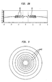
- FIGURE 2A is a schematic cross-sectional view of a truncated diffractive IOL according to one embodiment of the invention
- FIGURE 2B schematically depicts a truncated diffractive structure, composed of a plurality of diffractive elements, disposed on an anterior surface of the IOL of FIGURE 2A,
- FIGURE 3 is a schematic top view of the anterior surface of the IOL of FIGURE 2A, including diffractive zones disposed on that surface,
- FIGURE 4 illustrates theoretically calculated curves indicating the relative energy directed to near and far foci of a plurality of hypothetical truncated diffractive IOLs having diffractive structures with different diameters
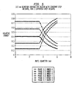
- FIGURE 5 presents a set of theoretically calculated curves depicting the distribution of optical energy between far and near foci of a plurality of truncated diffractive IOLs having different step heights at the boundaries of their diffractive zones as a function of pupil diameter
- FIGURE 6 is a schematic cross-sectional view of a diffractive IOL according to one embodiment of the invention having an apodized truncated diffractive structure on an anterior surface thereof,
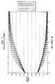
- FIGURE 7 presents a plurality of theoretically calculated curves illustrating the distribution of optical energy into near and far foci of a plurality of hypothetical apodized truncated diffractive lenses having diffractive structures with different diameters as a function of pupil diameter,
- FIGURE 8 presents graphs illustrating theoretical distribution of energy at a design wavelength, as a function of pupil diameter, between the near and far foci of a plurality of diffractive lenses having an apodized diffractive structure in accordance with one embodiment of the invention with different apodization parameters,
- FIGURE 9 is a schematic cross-sectional view of an IOL according to one embodiment of the invention having an aspherical anterior surface on which a truncated diffractive structure is disposed,
- FIGURE 10 is a schematic cross-sectional view of an IOL according to another embodiment of the invention having an anterior surface on a central portion of which a truncated diffractive structure is disposed surrounded by a peripheral portion lacking diffractive structures, wherein the central portion is characterized by a spherical base profile and the peripheral portion is characterized by an aspherical base profile,
- FIGURE 11 is a schematic side view of an ophthalmic lens according to one embodiment of the invention having an anterior surface with a toric base profile on which a truncated diffractive pattern is disposed.
- the present invention generally refers to diffractive ophthalmic lenses and methods for correcting vision that employ such lenses.
- IOLs intraocular lenses
- the teachings of the invention can also be applied to other ophthalmic lenses, such as contact lenses.
- the term "intraocular lens” and its abbreviation "IOL” are used herein interchangeably to describe lenses that are implanted into the interior of the eye to either replace the eye's natural lens or to otherwise augment vision regardless of whether or not the natural lens is removed.
- Intracorneal lenses and phakic intraocular lenses are examples of lenses that may be implanted into the eye without removal of the natural lens.
- the present invention provides a method of designing an ophthalmic lens, which utilizes a diffractive structure to optimize the visual performance of the lens by adjusting the distribution of optical energy directed to a near focus and a far focus for a range of pupil sizes.
- a diffractive ophthalmic lens in accordance with one such embodiment, an optic having an anterior refractive surface and a posterior refractive surface is provided, where the optic provides a far-focus power (step 1).
- a truncated diffractive structure is disposed on one of the surfaces for generating a near-focus add power (step 2).
- the diffractive structure can be adjusted so as to obtain a desired distribution of optical energy between the near and far foci for a range of pupil sizes (step 3).
- a number of parameters of the diffractive structure can be varied so as to adjust the distribution of the optical energy between the near and far foci.
- the size of the diffractive structure e.g., its radial extent and/or a number of diffractive zones comprising the structure, can be adjusted to obtain a desired shift in a ratio of optical energy in the far-focus relative to energy in the near-focus as the pupil size varies over a pre-defined range.
- the variation of the step heights can be designed to obtain a desired distribution of energy between the near and far foci.
- a variation of the step heights is typically accompanied by changes in other parameters of the diffractive structure, such as the surface curvature within a diffractive zone.
- the above method can be utilized to address differences in visual needs among different patients.
- variations of the pupil diameter (e.g., typical pupil diameter) among different patients can be addressed by providing different diffractive structures, each designed to provide a particular distribution of optical energy between the near and far foci for a given range of pupil sizes.
- the methods of the invention can be utilized to design an ophthalmic lens that is particularly suited to the visual needs of a patient, or a group of patients.
- the diffractive structure can be selected to transmit more of the optical energy to the far focus rather than the near focus.
- the diffractive structure can be designed to emphasize near vision.
- FIGURE 2A schematically depicts an intraocular lens (IOL) 18 according to one embodiment of the invention that includes an optic 20 having an anterior surface 22 and a posterior surface 24, as well as a plurality of fixation members or haptics 26 that facilitate placing the IOL in a patient's eye.
- IOL intraocular lens
- both surfaces 22 and 24 are generally convex, in other embodiments they can be concave or flat to provide other lens configurations, e.g., plano-convex.
- a diffractive structure 28 is disposed on a portion of the anterior surface 22, and is surrounded by a portion 30 of that surface that lacks any diffractive elements.
- the diffractive structure 28 is a truncated diffractive structure that covers only a portion of the surface 22.
- the lens 18 provides a far focus optical power, e.g., in a range of about 6 D to about 34 D (e.g., in a range of about 16 D to about 28 D), and an add power in a range of about 2 D to about 4 D, e.g., in a range of about 2.5 D to about 4 D or in a range of about 3 D to about 4 D.
- the near focus power can be, e.g., in a range of about 8 D to about 38 D.
- the curvatures of the surfaces 22 and 24, together with the index of refraction of the optic are configured to provide a desired far-focus optical power.
- the zero-diffraction order of the diffractive structure 28 transmits incident light substantially to the far focus while the first order of the diffractive structure transmits incident light to both the near and far foci.
- the diffractive structure provides a desired add power, e.g., in a range of about 3 D to about 4 D.
- the radial diameter of the optic can range, e.g., from about 5 mm to about 7 mm, while the radial diameter of the diffractive structure can range from about 2 mm to about 5 mm.
- FIGURE 2B more clearly depicts a plurality of different zones 30 that form the diffraction structure.
- the zero th and 1 st diffraction orders of the diffractive structure are employed for generating a near focus and a far focus, in other embodiments, other diffraction orders can be utilized for this purpose.
- the lens 18 can be formed of a variety of materials, preferably biocompatible. Some examples of suitable materials include, without limitation, a soft acrylic material utilized for forming commercial lenses commonly known as Acrysof, silicone and hydrogel. By way of further examples, U.S. Patent No. 6,416,550 , which is herein incorporated by reference, discloses materials suitable for forming the IOL 18.
- the diffractive structures 30 form a plurality of diffractive zones 32 separated from one another at their boundaries by a substantially uniform step height, which provides a selected phase shift at each zone boundary.
- the design wavelength ⁇ is chosen to be 550 nm green light at the center of visual response.
- the radius of the central zone ( r 0 ) can be set to be ⁇ f .
- step height p ⁇ n 2 - n 1
- ⁇ denotes the design wavelength (e.g., 550 nm)
- n 2 denotes the refractive index of the material from which the lens is formed
- n 1 denotes the refractive index of the medium in which the lens is placed
- p is a fraction, e.g., 0.5 or 0.7.
- the diffractive structure 28 can be adjusted to shift the ratio of optical energy directed to the near and far foci.
- the diameter of the diffractive structure 28 can be adjusted to vary this ratio.
- FIGURE 4 illustrates a plurality of theoretically calculated curves, indicating the relative energy directed to near and far foci for a plurality of diffractive lenses, such as the above lens 18, having truncated diffractive structures.
- Each diffractive structure is characterized by a substantially uniform step height generating a phase delay. In this exemplary embodiment, the phase delay between adjacent zones is about 0.7 ⁇ (where ⁇ was selected to be 550 nm).
- the diffractive structures are assumed to be disposed on a surface having a diameter of about 6 mm, with the diameter of the structures ranging from about 1.5 mm to about 4.5 mm.
- the step heights are selected such that for small pupil sizes, more of the energy is directed to the near focus with the ratio of the energy distributed between the near and far foci remaining substantially constant up to a threshold pupil size beyond which the energy directed to the near focus begins to decrease and the energy directed to the far focus begins to increase.
- the diameter of the diffractive structure can be selected so as to address the visual needs of a patient, or a patient population.
- the diffractive structure can be selected to have a smaller diameter (e.g., a diameter of 1.5 mm).
- the height of the step at the zone boundaries of the diffractive structure in the above diffractive lens 20 can be adjusted so as to shift the energy balance between the near and far foci.
- FIGURE 5 shows a set of curves that depict the distribution of energy between far and near foci of a plurality of diffractive lenses, such as the above lens 18, having different phase delays at the zone boundaries of their respective diffractive structures.
- the lenses were assumed to be formed of a material used in commercial lenses known as Acrysof.
- the diffractive structure of each lens was assumed to have a diameter of 3.5 mm and to be formed of a plurality of zones separated from one another by steps having uniform heights for generating phase delays.
- phase delays were employed for the three lenses: 0.5 ⁇ , 0.6 ⁇ and 0.7 ⁇ (where ⁇ was selected to be 550 nm).
- ⁇ was selected to be 550 nm.
- adjusting the step heights requires adjusting other parameters of the diffractive structures, such as the curvatures of the zones.
- the step heights at the diffractive zones vary as a function of their radial distance from the optical axis, that is, the step heights are apodized.
- FIGURE 6 depicts such an embodiment of an IOL 30 having an optic 32 comprising an anterior optical surface 34 and a posterior optical surface 36. Similar to the previous embodiment, the lens 30 includes haptics 38 that facilitate its placement in the eye. A truncated apodized diffractive structure 40 is disposed on a portion of the anterior surface. The lens 30 provides a far focus optical power, for example, in a range of about 6 D to about 34 D (e.g., in a range of about 16 D to about 28 D).
- the diffractive structure provides an add power in a range of about 2 D to about 4 D (e.g., in a range of about 3 D to about 4 D), so as to generate a near focus optical power (the effective add power when implanted in the eye can be somewhat different, e.g., in a range of about 1 D to about 3 D).
- apodized diffractive structure e.g., the diameter of the diffractive structure, phase height, and apodization exponent
- a diffractive structure with a larger diameter can be selected to divert more of the incident energy to the near focus (i.e., 1 st order diffraction).
- a different apodization of the step heights of the diffractive structure can be employed to obtain a different set of energy distribution curves indicative of the ratio of the incident light energy directed to the near and far foci.
- Diffraction Efficiency sin ⁇ ⁇ 2
- ⁇ ⁇ * b - p
- b b
- p denotes the diffraction order.
- the zero th order diffraction is typically associated with the distance lens power.
- h b * ⁇ n 2 - n 1
- ⁇ denotes the design wavelength (e.g., 550 nm)
- n 1 denotes the refractive index of a medium surrounding the lens (e.g., 1.336 ofIOLs)
- n 2 denotes the refractive index of the material forming the lens (e.g., 1.55 when Acrysoft is used to form the lens)
- the step heights follow the above relation up to a selected threshold step height (i.e., up to a certain radial location), beyond which the remaining step heights (the step heights at greater radial distances) decrease linearly to zero.
- FIGURE 8 presents graphs illustrating theoretical distribution of energy at a design wavelength (550 nm), as a function of pupil diameter, between the near and far foci of a plurality of diffractive lenses formed of Acrysof lens material.
- the diffractive lenses were designed as biconvex lenses providing an add power of about 4 Diopters.
- Each lens includes a diffractive structure characterized by step heights that are apodized in accordance with the above apodization function (Eq. 8), albeit with apodization parameters that are different than those utilized for the other lenses. More specifically, the lenses are characterized by different values of the parameters phase0, rolloff, and rcontrol.
- the parameters can be selected to maintain a substantially constant ratio of the optical energy directed to the near and far foci up to a selected pupil size, and to provide a ratio that varies as the pupil size grows beyond the selected value (e.g., the energy ratio would favor directing more of the light to the far focus for large pupil sizes).
- one or more surfaces of the IOL can include an aspherical profile so as to reduce spherical aberration.
- FIGURE 9 schematically depicts an IOL 42 according to such an embodiment of the invention having an optic 44 with an anterior surface 46 and a posterior surface 48.
- a diffractive structure 50 is far focus.
- the diffractive structure can be a truncated structure having substantially uniform step heights (such as that utilized in the above lens 18) or it can include apodized step heights.
- the anterior surface comprises an aspheric base profile, that is, a profile that is substantially coincident with a putative spherical profile 46a (shown by dashed lines) at small radial distances from an optical axis 52 but deviates from that spherical profile at greater radial distances.
- the conic constant ( k ) can be in a range of about -10 to about-1000.
- FIGURE 10 schematically presents an IOL 54 in accordance with another embodiment of the invention having an optic 56 with an anterior surface 58 and a posterior surface 60.
- a diffractive structure 62 characterized by substantially uniform or apodized step heights, is disposed on a portion of the anterior surface 58.
- a peripheral portion 59 of the anterior surface i.e., a portion of the surface surrounding the diffractive structure, is characterized by a substantially spherical profile.
- the central portion of the anterior surface i.e., a portion of the surface on which the diffractive structure is disposed, is characterized by an aspherical profile (shown by dashed lines), e.g., a profile defined by the above Eq. (9).
- the central portion is characterized by a spherical profile while the peripheral portion exhibits a selected degree of asphericity.
- the present invention discloses methods for correcting vision that can enhance the range of a patient's near vision and/or to provide a patient with not only far and near vision but also an intermediate vision.
- one diffractive IOL having one add power can be implanted in one eye of a patient and another diffractive IOL having a different add power can be implanted in the other eye.
- the difference in the add powers can be, e.g., in a range of about 0.1 D to about 1.5 D (e.g., in a range of about 0.2 to 1 D).
- a combination of the following add powers can be employed to enhance a patient's range of near vision: 4 D, 3.75 D, 3.5 D, 3.25 D and 3 D.
- two diffractive IOLs having substantially similar far focus powers but different add powers can be implanted in a patient's eyes (each in one eye of the patient) such that the IOL with the lower add power would provide a degree of intermediate vision and/or enhance the range of the near vision.
- the difference between the add powers of the two lenses can be selected such that their near vision energy curves would at least partially overlap so as to enhance the depth of focus for near vision.
- the above method of implanting a different IOL in each eye of a patient can be combined with the previous methods of optimizing the distribution of energy between the near and far foci so as to enhance a patient's vision.
- the diffractive structures of the lenses can be adjusted, in a manner discussed above, so as to optimize the incident light energy that is directed to the near focus over a range of pupil sizes.
- FIGURE 11 schematically illustrates a diffractive lens 62 according to such an embodiment of the invention that includes an anterior optical surface 64 and a posterior optical surface 66.
- a truncated diffractive structure 68 is disposed on the anterior surface.
- the diffractive structure is characterized by a plurality of diffractive zones separated from one another by substantially uniform step heights (in other embodiments, a diffractive structure with apodized step heights, e.g., a structure with step heights defined by the above Eq. (8), can be utilized).
- the anterior surface 64 includes a toric profile characterized by different curvatures in two orthogonal directions.
- the diffractive IOL (having a truncated diffractive structure characterized by a substantially uniform or a non-uniform step heights) can be formed of a material that can provide some filtering of the blue light.
- the IOL can be formed of Acrysof Natural material.
- U.S. Patent No. 5,470,932 herein incorporated by reference, discloses polymerizable yellow dyes that can be utilized to block or lower the intensity of blue light transmitted through ocular lenses.
Landscapes
- Health & Medical Sciences (AREA)
- Ophthalmology & Optometry (AREA)
- Physics & Mathematics (AREA)
- General Health & Medical Sciences (AREA)
- Optics & Photonics (AREA)
- General Physics & Mathematics (AREA)
- Engineering & Computer Science (AREA)
- Veterinary Medicine (AREA)
- Vascular Medicine (AREA)
- Life Sciences & Earth Sciences (AREA)
- Animal Behavior & Ethology (AREA)
- Biomedical Technology (AREA)
- Public Health (AREA)
- Heart & Thoracic Surgery (AREA)
- Transplantation (AREA)
- Oral & Maxillofacial Surgery (AREA)
- Cardiology (AREA)
- Prostheses (AREA)
- Eyeglasses (AREA)
- Diffracting Gratings Or Hologram Optical Elements (AREA)
Applications Claiming Priority (1)
| Application Number | Priority Date | Filing Date | Title |
|---|---|---|---|
| US11/444,112 US20070171362A1 (en) | 2004-12-01 | 2006-08-23 | Truncated diffractive intraocular lenses |
Publications (1)
| Publication Number | Publication Date |
|---|---|
| EP1891912A1 true EP1891912A1 (fr) | 2008-02-27 |
Family
ID=38476965
Family Applications (1)
| Application Number | Title | Priority Date | Filing Date |
|---|---|---|---|
| EP07114347A Withdrawn EP1891912A1 (fr) | 2006-08-23 | 2007-08-14 | Lentilles intraoculaires avec zone diffractive |
Country Status (13)
| Country | Link |
|---|---|
| US (2) | US20070171362A1 (fr) |
| EP (1) | EP1891912A1 (fr) |
| JP (1) | JP2008049167A (fr) |
| KR (1) | KR20080018146A (fr) |
| CN (1) | CN101129278A (fr) |
| AR (1) | AR062487A1 (fr) |
| AU (1) | AU2007209782A1 (fr) |
| BR (1) | BRPI0703530A (fr) |
| CA (1) | CA2597376A1 (fr) |
| IL (1) | IL185336A0 (fr) |
| MX (1) | MX2007010160A (fr) |
| RU (1) | RU2007131931A (fr) |
| TW (1) | TW200819117A (fr) |
Cited By (14)
| Publication number | Priority date | Publication date | Assignee | Title |
|---|---|---|---|---|
| EP2103279A1 (fr) * | 2008-03-19 | 2009-09-23 | Icon Lab GmbH | Lentille intraoculaire multifocale |
| EP2349093A4 (fr) * | 2008-11-20 | 2013-06-12 | Novartis Ag | Lentille intraoculaire multifocale diffractive avec zone de distance centrale modifiée |
| WO2015144299A1 (fr) * | 2014-03-26 | 2015-10-01 | Rodenstock Gmbh | Lentille ophtalmique améliorée pour la correction de la presbytie |
| US9320594B2 (en) | 2009-02-12 | 2016-04-26 | The Arizona Board Of Regents On Behalf Of The University Of Arizona | Diffractive trifocal lens |
| EP3300694A1 (fr) * | 2016-09-30 | 2018-04-04 | Sav-Iol Sa | Procede de determination de parametres geometriques d'une lentille ophtalmique et lentille ophtalmique obtenue par l'execution dudit procede |
| US11022815B2 (en) | 2012-08-31 | 2021-06-01 | Amo Groningen B.V. | Multi-ring lens, systems and methods for extended depth of focus |
| US11129707B2 (en) | 2015-08-12 | 2021-09-28 | Physiol S.A. | Trifocal intraocular lens with extended range of vision and correction of longitudinal chromatic aberration |
| US11156853B2 (en) | 2017-06-28 | 2021-10-26 | Amo Groningen B.V. | Extended range and related intraocular lenses for presbyopia treatment |
| US11262598B2 (en) | 2017-06-28 | 2022-03-01 | Amo Groningen, B.V. | Diffractive lenses and related intraocular lenses for presbyopia treatment |
| US11327210B2 (en) | 2017-06-30 | 2022-05-10 | Amo Groningen B.V. | Non-repeating echelettes and related intraocular lenses for presbyopia treatment |
| US11497599B2 (en) | 2017-03-17 | 2022-11-15 | Amo Groningen B.V. | Diffractive intraocular lenses for extended range of vision |
| US11523897B2 (en) | 2017-06-23 | 2022-12-13 | Amo Groningen B.V. | Intraocular lenses for presbyopia treatment |
| US11844689B2 (en) | 2019-12-30 | 2023-12-19 | Amo Groningen B.V. | Achromatic lenses and lenses having diffractive profiles with irregular width for vision treatment |
| US12204178B2 (en) | 2018-12-06 | 2025-01-21 | Amo Groningen B.V. | Diffractive lenses for presbyopia treatment |
Families Citing this family (48)
| Publication number | Priority date | Publication date | Assignee | Title |
|---|---|---|---|---|
| US7481532B2 (en) * | 2006-02-09 | 2009-01-27 | Alcon, Inc. | Pseudo-accommodative IOL having multiple diffractive patterns |
| US7572007B2 (en) * | 2006-08-02 | 2009-08-11 | Alcon, Inc. | Apodized diffractive IOL with frustrated diffractive region |
| US20090062911A1 (en) * | 2007-08-27 | 2009-03-05 | Amo Groningen Bv | Multizonal lens with extended depth of focus |
| US8974526B2 (en) | 2007-08-27 | 2015-03-10 | Amo Groningen B.V. | Multizonal lens with extended depth of focus |
| US8740978B2 (en) * | 2007-08-27 | 2014-06-03 | Amo Regional Holdings | Intraocular lens having extended depth of focus |
| US8747466B2 (en) * | 2007-08-27 | 2014-06-10 | Amo Groningen, B.V. | Intraocular lens having extended depth of focus |
| US9216080B2 (en) | 2007-08-27 | 2015-12-22 | Amo Groningen B.V. | Toric lens with decreased sensitivity to cylinder power and rotation and method of using the same |
| US20090088840A1 (en) * | 2007-10-02 | 2009-04-02 | Simpson Michael J | Zonal diffractive multifocal intraocular lenses |
| ATE523810T1 (de) * | 2008-02-15 | 2011-09-15 | Amo Regional Holdings | System, brillenglas und verfahren zur erweiterung der fokustiefe |
| US8439498B2 (en) | 2008-02-21 | 2013-05-14 | Abbott Medical Optics Inc. | Toric intraocular lens with modified power characteristics |
| US8231219B2 (en) * | 2008-04-24 | 2012-07-31 | Amo Groningen B.V. | Diffractive lens exhibiting enhanced optical performance |
| US7871162B2 (en) * | 2008-04-24 | 2011-01-18 | Amo Groningen B.V. | Diffractive multifocal lens having radially varying light distribution |
| US8231673B2 (en) * | 2008-05-06 | 2012-07-31 | Novartis Ag | Non-invasive power adjustable intraocular lens |
| US8862447B2 (en) | 2010-04-30 | 2014-10-14 | Amo Groningen B.V. | Apparatus, system and method for predictive modeling to design, evaluate and optimize ophthalmic lenses |
| US8216307B2 (en) * | 2008-12-19 | 2012-07-10 | Novartis Ag | Radially segmented apodized diffractive multifocal design for ocular implant |
| US8529060B2 (en) * | 2009-02-19 | 2013-09-10 | Alcon Research, Ltd. | Intraocular lens alignment using corneal center |
| EP2473876A1 (fr) * | 2009-09-01 | 2012-07-11 | Arthur Bradley | Correction multifocale assurant une qualité améliorée de la vision |
| JP5460211B2 (ja) * | 2009-09-29 | 2014-04-02 | 株式会社ニデック | 多焦点眼内レンズ |
| AU2010313599B2 (en) * | 2009-10-26 | 2015-08-13 | Alcon Inc. | Phase-shifted center-distance diffractive design for ocular implant |
| GB2475550B (en) * | 2009-11-23 | 2012-09-12 | Rayner Intraocular Lenses Ltd | Intraocular lens |
| CA2784782C (fr) | 2009-12-18 | 2018-02-27 | Hendrik A. Weeber | Lentille a echelette limitee, systemes et procedes |
| EP3330776A1 (fr) | 2010-12-01 | 2018-06-06 | AMO Groningen B.V. | Lentille multifocale ayant une progression de puissance optique et système et procédé permettant de la fournir |
| US9931200B2 (en) | 2010-12-17 | 2018-04-03 | Amo Groningen B.V. | Ophthalmic devices, systems, and methods for optimizing peripheral vision |
| US8894204B2 (en) | 2010-12-17 | 2014-11-25 | Abbott Medical Optics Inc. | Ophthalmic lens, systems and methods having at least one rotationally asymmetric diffractive structure |
| CN102354359B (zh) * | 2011-07-18 | 2014-12-17 | 惠州Tcl移动通信有限公司 | 移动设备及其瞳孔识别方法 |
| US8556417B2 (en) * | 2012-02-02 | 2013-10-15 | Novartis Ag | Apodized hybrid diffractive-refractive IOL for pseudo-accommodation |
| EP2928413B1 (fr) | 2012-12-04 | 2019-08-14 | AMO Groningen B.V. | Lentilles, systèmes et procédés pour fournir des traitements personnalisés binoculaires pour corriger une presbytie |
| KR20150096383A (ko) | 2012-12-18 | 2015-08-24 | 노바르티스 아게 | 개선된 심도를 가진 안구내 렌즈 제공 방법 및 시스템 |
| CA2902075C (fr) | 2013-02-28 | 2018-08-14 | Richard Honigsbaum | Une bague de mise sous tension servant a retablir les forces centripetes de la capsule anterieure par capsulorhexie et capsules exemplaires comportant des lentilles intraoculairesaccommodante et restorees par ladite bague |
| US9561098B2 (en) | 2013-03-11 | 2017-02-07 | Abbott Medical Optics Inc. | Intraocular lens that matches an image surface to a retinal shape, and method of designing same |
| WO2015136380A2 (fr) | 2014-03-10 | 2015-09-17 | Amo Groningen B.V. | Lentilles intraoculaires superposées qui améliorent la vision globale là où il y a une perte locale de la fonction rétinienne |
| EP4445870A3 (fr) | 2014-04-21 | 2024-12-25 | Amo Groningen B.V. | Dispositifs ophtalmiques, système et procédés pour améliorer la vision périphérique |
| US9335564B2 (en) * | 2014-05-15 | 2016-05-10 | Novartis Ag | Multifocal diffractive ophthalmic lens using suppressed diffractive order |
| EP3413840A1 (fr) | 2016-02-09 | 2018-12-19 | AMO Groningen B.V. | Lentille intraoculaire progressive et ses procédés d'utilisation et de fabrication |
| US9968440B2 (en) * | 2016-02-29 | 2018-05-15 | Novartis Ag | Ophthalmic lens having an extended depth of focus |
| EP3426191B1 (fr) | 2016-03-11 | 2024-09-11 | Amo Groningen B.V. | Lentilles intraoculaires améliorant la vision périphérique |
| US11123178B2 (en) | 2016-03-23 | 2021-09-21 | Johnson & Johnson Surgical Vision, Inc. | Power calculator for an ophthalmic apparatus with corrective meridians having extended tolerance or operation band |
| AU2017238517B2 (en) | 2016-03-23 | 2021-11-11 | Johnson & Johnson Surgical Vision, Inc. | Ophthalmic apparatus with corrective meridians having extended tolerance band |
| US11096778B2 (en) | 2016-04-19 | 2021-08-24 | Amo Groningen B.V. | Ophthalmic devices, system and methods that improve peripheral vision |
| WO2018078439A2 (fr) | 2016-10-25 | 2018-05-03 | Amo Groningen B.V. | Modèles oculaires réalistes pour modéliser et évaluer des lentilles intraoculaires pour un grand champ de vision |
| US10739227B2 (en) | 2017-03-23 | 2020-08-11 | Johnson & Johnson Surgical Vision, Inc. | Methods and systems for measuring image quality |
| KR102142537B1 (ko) * | 2017-08-11 | 2020-08-07 | 한국과학기술원 | 평판 메타렌즈 및 이를 포함하는 커버글라스 |
| WO2019106067A1 (fr) | 2017-11-30 | 2019-06-06 | Amo Groningen B.V. | Lentilles intraoculaires permettant d'améliorer l'indépendance vis à vis des lunettes après une intervention chirurgicale et leurs procédés de fabrication |
| EP3731781B1 (fr) * | 2017-12-28 | 2022-02-23 | Medicontur Orvostechnikai KFT. | Lentille ophtalmique artificielle de diffraction à apodisation optimisée et procédé de fabrication d'une telle lentille ophtalmique artificielle |
| KR102235954B1 (ko) | 2019-04-24 | 2021-04-02 | 건국대학교 산학협력단 | 토양조류의 광합성 형광 이미지를 이용한 토양 독성 평가 방법 |
| US11886046B2 (en) | 2019-12-30 | 2024-01-30 | Amo Groningen B.V. | Multi-region refractive lenses for vision treatment |
| EP4333685B1 (fr) | 2021-05-05 | 2026-01-14 | AMO Groningen B.V. | Système d'halomètre annulaire et procédé de quantification de dysphotopsies |
| US12544218B2 (en) | 2021-12-03 | 2026-02-10 | Amo Groningen B.V. | Lenses having multi-ring design for vision treatment |
Citations (8)
| Publication number | Priority date | Publication date | Assignee | Title |
|---|---|---|---|---|
| US5470932A (en) * | 1993-10-18 | 1995-11-28 | Alcon Laboratories, Inc. | Polymerizable yellow dyes and their use in opthalmic lenses |
| US5699142A (en) * | 1994-09-01 | 1997-12-16 | Alcon Laboratories, Inc. | Diffractive multifocal ophthalmic lens |
| US6416550B2 (en) * | 1998-04-15 | 2002-07-09 | Alcon Manufacturing, Ltd. | Method of selecting an intraocular lens material |
| US20060116764A1 (en) * | 2004-12-01 | 2006-06-01 | Simpson Michael J | Apodized aspheric diffractive lenses |
| EP1818023A1 (fr) * | 2006-02-09 | 2007-08-15 | Alcon Manufacturing, Ltd. | Dispositif intraoculaire avec de multiples énergies/optiques de focalisation |
| WO2007092948A1 (fr) * | 2006-02-09 | 2007-08-16 | Alcon Research, Ltd. | Lentilles intraoculaires à pseudo accommodatrices à plusieurs réseaux diffracteurs |
| EP1862147A1 (fr) * | 2006-05-31 | 2007-12-05 | Alcon, Inc | Correction d'aberrations chromatiques dans des lentilles intraoculaires |
| EP1884219A2 (fr) * | 2006-08-02 | 2008-02-06 | Alcon Manufacturing, Ltd. | Lentille intraoculaire apodisée avec une région diffractive frustrée |
Family Cites Families (7)
| Publication number | Priority date | Publication date | Assignee | Title |
|---|---|---|---|---|
| US5096285A (en) * | 1990-05-14 | 1992-03-17 | Iolab Corporation | Multifocal multizone diffractive ophthalmic lenses |
| US5760871A (en) * | 1993-01-06 | 1998-06-02 | Holo-Or Ltd. | Diffractive multi-focal lens |
| GB9301614D0 (en) * | 1993-01-27 | 1993-03-17 | Pilkington Diffractive Lenses | Multifocal contact lens |
| DE4403326C1 (de) * | 1994-02-03 | 1995-06-22 | Hans Reinhard Prof Dr Koch | Intraokulare Linsenanordnung zur Astigmatismuskorrektur |
| US6364483B1 (en) * | 2000-02-22 | 2002-04-02 | Holo Or Ltd. | Simultaneous multifocal contact lens and method of utilizing same for treating visual disorders |
| US7896916B2 (en) * | 2002-11-29 | 2011-03-01 | Amo Groningen B.V. | Multifocal ophthalmic lens |
| SE0203564D0 (sv) * | 2002-11-29 | 2002-11-29 | Pharmacia Groningen Bv | Multifocal opthalmic lens |
-
2006
- 2006-08-23 US US11/444,112 patent/US20070171362A1/en not_active Abandoned
-
2007
- 2007-08-14 EP EP07114347A patent/EP1891912A1/fr not_active Withdrawn
- 2007-08-15 CA CA002597376A patent/CA2597376A1/fr not_active Abandoned
- 2007-08-16 IL IL185336A patent/IL185336A0/en unknown
- 2007-08-16 AU AU2007209782A patent/AU2007209782A1/en not_active Abandoned
- 2007-08-21 MX MX2007010160A patent/MX2007010160A/es not_active Application Discontinuation
- 2007-08-22 RU RU2007131931/28A patent/RU2007131931A/ru not_active Application Discontinuation
- 2007-08-22 AR ARP070103732A patent/AR062487A1/es not_active Application Discontinuation
- 2007-08-22 JP JP2007215463A patent/JP2008049167A/ja active Pending
- 2007-08-22 TW TW096131066A patent/TW200819117A/zh unknown
- 2007-08-23 KR KR1020070084854A patent/KR20080018146A/ko not_active Withdrawn
- 2007-08-23 BR BRPI0703530-6A patent/BRPI0703530A/pt not_active IP Right Cessation
- 2007-08-23 CN CNA2007101427964A patent/CN101129278A/zh active Pending
-
2010
- 2010-07-30 US US12/847,214 patent/US20110022170A1/en not_active Abandoned
Patent Citations (8)
| Publication number | Priority date | Publication date | Assignee | Title |
|---|---|---|---|---|
| US5470932A (en) * | 1993-10-18 | 1995-11-28 | Alcon Laboratories, Inc. | Polymerizable yellow dyes and their use in opthalmic lenses |
| US5699142A (en) * | 1994-09-01 | 1997-12-16 | Alcon Laboratories, Inc. | Diffractive multifocal ophthalmic lens |
| US6416550B2 (en) * | 1998-04-15 | 2002-07-09 | Alcon Manufacturing, Ltd. | Method of selecting an intraocular lens material |
| US20060116764A1 (en) * | 2004-12-01 | 2006-06-01 | Simpson Michael J | Apodized aspheric diffractive lenses |
| EP1818023A1 (fr) * | 2006-02-09 | 2007-08-15 | Alcon Manufacturing, Ltd. | Dispositif intraoculaire avec de multiples énergies/optiques de focalisation |
| WO2007092948A1 (fr) * | 2006-02-09 | 2007-08-16 | Alcon Research, Ltd. | Lentilles intraoculaires à pseudo accommodatrices à plusieurs réseaux diffracteurs |
| EP1862147A1 (fr) * | 2006-05-31 | 2007-12-05 | Alcon, Inc | Correction d'aberrations chromatiques dans des lentilles intraoculaires |
| EP1884219A2 (fr) * | 2006-08-02 | 2008-02-06 | Alcon Manufacturing, Ltd. | Lentille intraoculaire apodisée avec une région diffractive frustrée |
Cited By (29)
| Publication number | Priority date | Publication date | Assignee | Title |
|---|---|---|---|---|
| EP2103279A1 (fr) * | 2008-03-19 | 2009-09-23 | Icon Lab GmbH | Lentille intraoculaire multifocale |
| EP2349093A4 (fr) * | 2008-11-20 | 2013-06-12 | Novartis Ag | Lentille intraoculaire multifocale diffractive avec zone de distance centrale modifiée |
| US11199725B2 (en) | 2009-02-12 | 2021-12-14 | Arizona Board Of Regents On Behalf Of The University Of Arizona | Diffractive trifocal lens |
| US12339526B2 (en) | 2009-02-12 | 2025-06-24 | Arizona Board Of Regents On Behalf Of The University Of Arizona | Diffractive trifocal lens |
| US12164181B2 (en) | 2009-02-12 | 2024-12-10 | Arizona Board Of Regents On Behalf Of The University Of Arizona | Diffractive trifocal lens |
| US11693260B2 (en) | 2009-02-12 | 2023-07-04 | Arizona Board Of Regents On Behalf Of The University Of Arizona | Diffractive trifocal lens |
| US9320594B2 (en) | 2009-02-12 | 2016-04-26 | The Arizona Board Of Regents On Behalf Of The University Of Arizona | Diffractive trifocal lens |
| US10209533B2 (en) | 2009-02-12 | 2019-02-19 | The Arizona Board Of Regents On Behalf Of The University Of Arizona | Diffractive trifocal lens |
| US10725320B2 (en) | 2009-02-12 | 2020-07-28 | Arizona Board Of Regents On Behalf Of The University Of Arizona | Diffractive trifocal lens |
| EP2396683B1 (fr) | 2009-02-12 | 2020-04-08 | The Arizona Board Of Regents On Behalf Of The University Of Arizona | Verre triple foyer à diffraction |
| US11022815B2 (en) | 2012-08-31 | 2021-06-01 | Amo Groningen B.V. | Multi-ring lens, systems and methods for extended depth of focus |
| US12158638B2 (en) | 2012-08-31 | 2024-12-03 | Amo Groningen B.V. | Multi-ring lens, systems and methods for extended depth of focus |
| WO2015144299A1 (fr) * | 2014-03-26 | 2015-10-01 | Rodenstock Gmbh | Lentille ophtalmique améliorée pour la correction de la presbytie |
| US10175505B2 (en) | 2014-03-26 | 2019-01-08 | Rodenstock Gmbh | Ophthalmic lens for presbyopia correction |
| US11129707B2 (en) | 2015-08-12 | 2021-09-28 | Physiol S.A. | Trifocal intraocular lens with extended range of vision and correction of longitudinal chromatic aberration |
| CN109789013A (zh) * | 2016-09-30 | 2019-05-21 | 赛弗-伊奥尔股份有限公司 | 用于制造眼内眼科透镜的方法以及通过实现该方法获得的眼科透镜 |
| WO2018060319A1 (fr) * | 2016-09-30 | 2018-04-05 | Sav-Iol Sa | Procédé de fabrication d'une lentille ophtalmique intraoculaire et lentille ophtalmique obtenue par la mise en œuvre de ce procédé |
| EP3300694A1 (fr) * | 2016-09-30 | 2018-04-04 | Sav-Iol Sa | Procede de determination de parametres geometriques d'une lentille ophtalmique et lentille ophtalmique obtenue par l'execution dudit procede |
| US11497599B2 (en) | 2017-03-17 | 2022-11-15 | Amo Groningen B.V. | Diffractive intraocular lenses for extended range of vision |
| US12465482B2 (en) | 2017-03-17 | 2025-11-11 | Amo Groningen B.V. | Diffractive intraocular lenses for extended range of vision |
| US11523897B2 (en) | 2017-06-23 | 2022-12-13 | Amo Groningen B.V. | Intraocular lenses for presbyopia treatment |
| US11262598B2 (en) | 2017-06-28 | 2022-03-01 | Amo Groningen, B.V. | Diffractive lenses and related intraocular lenses for presbyopia treatment |
| US11573433B2 (en) | 2017-06-28 | 2023-02-07 | Amo Groningen B.V. | Extended range and related intraocular lenses for presbyopia treatment |
| US11914229B2 (en) | 2017-06-28 | 2024-02-27 | Amo Groningen B.V. | Diffractive lenses and related intraocular lenses for presbyopia treatment |
| US11156853B2 (en) | 2017-06-28 | 2021-10-26 | Amo Groningen B.V. | Extended range and related intraocular lenses for presbyopia treatment |
| US11327210B2 (en) | 2017-06-30 | 2022-05-10 | Amo Groningen B.V. | Non-repeating echelettes and related intraocular lenses for presbyopia treatment |
| US12204178B2 (en) | 2018-12-06 | 2025-01-21 | Amo Groningen B.V. | Diffractive lenses for presbyopia treatment |
| US12447009B2 (en) | 2019-12-30 | 2025-10-21 | Amo Groningen B.V. | Achromatic lenses and lenses having diffractive profiles with irregular width for vision treatment |
| US11844689B2 (en) | 2019-12-30 | 2023-12-19 | Amo Groningen B.V. | Achromatic lenses and lenses having diffractive profiles with irregular width for vision treatment |
Also Published As
| Publication number | Publication date |
|---|---|
| TW200819117A (en) | 2008-05-01 |
| IL185336A0 (en) | 2008-01-06 |
| MX2007010160A (es) | 2009-01-30 |
| US20110022170A1 (en) | 2011-01-27 |
| BRPI0703530A (pt) | 2008-04-22 |
| RU2007131931A (ru) | 2009-02-27 |
| KR20080018146A (ko) | 2008-02-27 |
| CA2597376A1 (fr) | 2008-02-23 |
| JP2008049167A (ja) | 2008-03-06 |
| AU2007209782A1 (en) | 2008-03-13 |
| US20070171362A1 (en) | 2007-07-26 |
| CN101129278A (zh) | 2008-02-27 |
| AR062487A1 (es) | 2008-11-12 |
Similar Documents
| Publication | Publication Date | Title |
|---|---|---|
| EP1891912A1 (fr) | Lentilles intraoculaires avec zone diffractive | |
| EP2045648B1 (fr) | Lentilles intraoculaires multifocale à diffraction zonale | |
| EP2286765B1 (fr) | Lentille intraoculaire apodisée avec une région diffractive frustrée | |
| EP2349093B1 (fr) | Lentille intraoculaire multifocale diffractive avec zone de distance centrale modifiée | |
| RU2538934C2 (ru) | Интерокулярная линза с переменной коррекцией хроматической аберрации | |
| HK1162688A (en) | Zonal diffractive multifocal intraocular lenses | |
| HK1154480B (en) | Apodized iol with frustrated diffractive region | |
| HK1162687A (en) | Zonal diffractive trifocal intraocular lenses | |
| HK1113998B (en) | Apodized iol with frustrated diffractive region |
Legal Events
| Date | Code | Title | Description |
|---|---|---|---|
| PUAI | Public reference made under article 153(3) epc to a published international application that has entered the european phase |
Free format text: ORIGINAL CODE: 0009012 |
|
| AK | Designated contracting states |
Kind code of ref document: A1 Designated state(s): AT BE BG CH CY CZ DE DK EE ES FI FR GB GR HU IE IS IT LI LT LU LV MC MT NL PL PT RO SE SI SK TR |
|
| AX | Request for extension of the european patent |
Extension state: AL BA HR MK YU |
|
| RAP1 | Party data changed (applicant data changed or rights of an application transferred) |
Owner name: ALCON RESEARCH, LTD. |
|
| 17P | Request for examination filed |
Effective date: 20080825 |
|
| AKX | Designation fees paid |
Designated state(s): AT BE BG CH CY CZ DE DK EE ES FI FR GB GR HU IE IS IT LI LT LU LV MC MT NL PL PT RO SE SI SK TR |
|
| 17Q | First examination report despatched |
Effective date: 20081113 |
|
| R17C | First examination report despatched (corrected) |
Effective date: 20100810 |
|
| STAA | Information on the status of an ep patent application or granted ep patent |
Free format text: STATUS: THE APPLICATION IS DEEMED TO BE WITHDRAWN |
|
| 18D | Application deemed to be withdrawn |
Effective date: 20111122 |