EP1892017A2 - Appareil d'extension et de flexion pour tuyau de drainage de camion de pompiers - Google Patents
Appareil d'extension et de flexion pour tuyau de drainage de camion de pompiers Download PDFInfo
- Publication number
- EP1892017A2 EP1892017A2 EP07015309A EP07015309A EP1892017A2 EP 1892017 A2 EP1892017 A2 EP 1892017A2 EP 07015309 A EP07015309 A EP 07015309A EP 07015309 A EP07015309 A EP 07015309A EP 1892017 A2 EP1892017 A2 EP 1892017A2
- Authority
- EP
- European Patent Office
- Prior art keywords
- drainpipe
- ladder
- bending apparatus
- extension
- bending
- Prior art date
- Legal status (The legal status is an assumption and is not a legal conclusion. Google has not performed a legal analysis and makes no representation as to the accuracy of the status listed.)
- Withdrawn
Links
- 238000005452 bending Methods 0.000 title claims abstract description 48
- XLYOFNOQVPJJNP-UHFFFAOYSA-N water Substances O XLYOFNOQVPJJNP-UHFFFAOYSA-N 0.000 claims abstract description 18
- 238000007789 sealing Methods 0.000 claims description 4
- 238000007599 discharging Methods 0.000 claims description 2
- 230000000694 effects Effects 0.000 description 4
- 230000001934 delay Effects 0.000 description 1
- 238000005516 engineering process Methods 0.000 description 1
- 239000004744 fabric Substances 0.000 description 1
Images

Classifications
-
- A—HUMAN NECESSITIES
- A62—LIFE-SAVING; FIRE-FIGHTING
- A62C—FIRE-FIGHTING
- A62C27/00—Fire-fighting land vehicles
-
- E—FIXED CONSTRUCTIONS
- E06—DOORS, WINDOWS, SHUTTERS, OR ROLLER BLINDS IN GENERAL; LADDERS
- E06C—LADDERS
- E06C5/00—Ladders characterised by being mounted on undercarriages or vehicles Securing ladders on vehicles
- E06C5/02—Ladders characterised by being mounted on undercarriages or vehicles Securing ladders on vehicles with rigid longitudinal members
- E06C5/04—Ladders characterised by being mounted on undercarriages or vehicles Securing ladders on vehicles with rigid longitudinal members capable of being elevated or extended ; Fastening means during transport, e.g. mechanical, hydraulic
-
- A—HUMAN NECESSITIES
- A62—LIFE-SAVING; FIRE-FIGHTING
- A62C—FIRE-FIGHTING
- A62C33/00—Hose accessories
Definitions
- hinged ladders are applied on fire trucks, of which upper part can be bent toward the building to aim the drainpipe at fire point and allow the ladder supported by the building exterior for stability of the ladder.
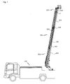
- Fig. 1 shows the structure of the high elevated ladder of fire truck in accordance with the present invention.
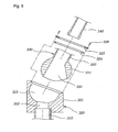
- Fig. 5 is a partial exploded perspective view of Fig. 3.
- the present invention presents extendable telescopic drainpipe along ladder, having a bending apparatus at the position corresponding to the hinged point of the ladder, in order to provide a drainpipe without additional joint member up to the top of the ladder.
- the extension and bending apparatus for fire truck drainpipe in accordance with the present invention is,
- the said bending apparatus is formed with hemispherical mounting groove inside the upper member and inlet hole, inside the lower part, connected with drainpipe,
- Fig. 1 shows the structure of elevated ladder for fire trucks applied with the present invention.
- An extendable ladder(200) is installed on fire truck(100), and on the side of the ladder(200) a metallic drainpipe(300) is installed.
- the said drainpipe(300) consists with multiple metallic drainpipes(301, 303, 304) of different diameters, connected telescopically for free extension and shrinking.
- the drainpipe(301) which has the largest diameter is mounted on the ladder(200) with supporting rod(302).
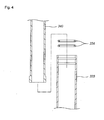
- At the top and bottom of the drainpipe(301) are formed with telescopic columns(305, 306) in which upper and lower drainpipes(303,304) are inserted and can slide in and out.
- the said telescopic columns(305, 306) have sealing members inside to prevent upper and lower drainpipes(303, 304) from being isolated and fire water from leaking out.
- the upper pipe(304) When the ladder(200) is being shrunk, the upper pipe(304) is inserted into the large pipe(301). When the upper pipe(304) has been inserted completely, the large pipe(301) moves downward with the ladder(200) receiving the lower pipe(303) inside.
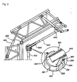
- the upper part of the said ladder(200) can be bent with a hinge(230) for easier approach to tall buildings and control of fire water discharging point.
- the drainpipe(300) When the ladder(200) is bent, the drainpipe(300) also has to be bent at the same position with a bending apparatus(A) to enable watering at objective fire point.
- the upper part of the ladder(200) can be bent to form a bendable ladder(210) of which one side of the bending direction is coupled with the upper part of the ladder(200) with a hinge(230) so that the upper part can be bent by rotation, while the other side is joined with the cylinder rod of hydraulic cylinder(220) of which main body is joined with the opposite side of the ladder(200).
- the upper part of the drainpipe(300) has to be able to be bent at the position where the bendable ladder(210) is bent to enable watering at desired direction.
- a bending apparatus(A) is provided.
- the said bending apparatus(A) consists with fixed a member(320) and a rotating member(330). Bending is implemented by the rotation of the rotating member(33) inside the fixed member(320).
- the said fixed member(320) is formed with hemispherical mounting groove(323) inside its body where the rotating member(330) which has ball-shaped body(331) is coupled by ball-joint type.
- the said fixed member(320) is formed with an inlet(322), at the bottom of the mounting grove(323), which is connected with the exterior of the body(321).
- the upper drainpipe(304) on the lower side is joined with the bottom of the body(321) of the fixed member(320) and connected with the inlet(322) to enable the fire water coming in through the upper pipe(304) can flow into the body(321) of the fixed member.
- the body(331) of the rotating member(330) is mounted on the said mounting groove(323), having the diameter same as the inner diameter of the mounting groove(323), and formed with a pipe connection hole(332) inside.
- an outlet(333) which is extended in a certain length, as a pipe, which is formed to connect the water flow path on top of the pipe connection hole(332) of the body(331).
- the bottom of said pipe connection hole(332) has larger diameter than top, and desirably, has the diameter expanded towards the direction of bending.
- the pipe connection hole(322) can maintain connection with the inlet(322) when the rotating member(330) is bent.
- an o-ring type sealing member(324) is mounted on top of the mounting groove(323) and bottom of said holding member(325) to prevent water coming in through inlet(322) from leaking out of the fixing member body(321).
- a pipe-type outlet(333) is formed in connection with the pipe connection hole(332), inside of which is inserted with the bottom of the bending drainpipe(340), and o-ring type sealing member(334) is mounted inside the outlet(333) to prevent water from leaking.
- the bottom of the bending drainpipe(340) has a certain amount of gap to the pipe connection hole(332) which is formed on the rotating member body(331). This is because, since the upper part of the bending drainpipe(340) is fixed to the upper part of the bending ladder(210) with a bracket-type pipe fixing member(340), there should be some free space to prevent interference between the bottom of the bending drainpipe(340) and pipe connection hole(332) when the drainpipe(340) is inserted into the pipe connection hole(332) for bending, as shown in Fig. 3.
- the drainpipe(300) is shrunk according to the bending of the ladder(210) since the bottom of the upper drainpipe(304) which is connected with the bottom of the fixing member(320) is inserted into the large drainpipe(301) by a certain length.
- the fire water fed from ground comes into the inlet(322) through the lower drainpipe(310) and discharged through the pipe connection hole(332) and outlet(333), and to desired fire point through the upper drainpipe(340).
- a telescopic drainpipe is installed along with the ladder, the drainpipe can be bent in correspondence with the bending of the ladder, to extend the drainpipe up to the top of the ladder, enabling fire water discharged towards the fire point accurately maintaining the water pressure.
- the bottom of the bendable drainpipe(340) is inserted into the pipe connection hole, and at the same time, the upper drainpipe(304) is inserted into the large pipe(301) in the telescopic column(306), to enable smooth bending of the drainpipe preventing deflection or damage.
Landscapes
- Engineering & Computer Science (AREA)
- Mechanical Engineering (AREA)
- Health & Medical Sciences (AREA)
- Public Health (AREA)
- Business, Economics & Management (AREA)
- Emergency Management (AREA)
- Fire-Extinguishing By Fire Departments, And Fire-Extinguishing Equipment And Control Thereof (AREA)
- Ladders (AREA)
Applications Claiming Priority (1)
| Application Number | Priority Date | Filing Date | Title |
|---|---|---|---|
| KR1020060078520A KR100769861B1 (ko) | 2006-08-21 | 2006-08-21 | 소방차 방수관의 신축 및 굴절 장치 |
Publications (1)
| Publication Number | Publication Date |
|---|---|
| EP1892017A2 true EP1892017A2 (fr) | 2008-02-27 |
Family
ID=38649968
Family Applications (1)
| Application Number | Title | Priority Date | Filing Date |
|---|---|---|---|
| EP07015309A Withdrawn EP1892017A2 (fr) | 2006-08-21 | 2007-08-03 | Appareil d'extension et de flexion pour tuyau de drainage de camion de pompiers |
Country Status (3)
| Country | Link |
|---|---|
| EP (1) | EP1892017A2 (fr) |
| JP (1) | JP2008049163A (fr) |
| KR (1) | KR100769861B1 (fr) |
Cited By (6)
| Publication number | Priority date | Publication date | Assignee | Title |
|---|---|---|---|---|
| CN102777128A (zh) * | 2012-08-14 | 2012-11-14 | 连云港黄海机械股份有限公司 | 一种折叠式钻塔 |
| CN114887263A (zh) * | 2022-04-20 | 2022-08-12 | 湖南宏迅消防安全工程有限公司 | 一种灭火救援辅助系统 |
| DE102022105086A1 (de) | 2022-03-03 | 2023-09-07 | Rosenbauer International Ag | Ausfahrbarer Leitersatz mit mehreren Leiterteilen |
| DE102022105087A1 (de) | 2022-03-03 | 2023-09-07 | Rosenbauer International Ag | Hubeinheit mit einem teleskopierbar ausgebildeten Auslegerarm und einer Spannvorrichtung |
| DE102022109721A1 (de) | 2022-04-22 | 2023-10-26 | Rosenbauer International Ag | Verfahren zur Bildung einer Zufuhrleitung für die Zuleitung eines Löschmittels an einem Leitersatz sowie Leitersatz mit einer Zufuhrleitung |
| IT202200010415A1 (it) * | 2022-05-19 | 2023-11-19 | Magirus Gmbh | Assieme di scala telescopica migliorata per un veicolo antincendio |
Families Citing this family (1)
| Publication number | Priority date | Publication date | Assignee | Title |
|---|---|---|---|---|
| KR101686188B1 (ko) * | 2015-04-28 | 2016-12-28 | (주)화담알앤알 | 자동형 소방 모니터 |
Family Cites Families (8)
| Publication number | Priority date | Publication date | Assignee | Title |
|---|---|---|---|---|
| JPS6344633Y2 (fr) * | 1980-10-18 | 1988-11-18 | ||
| JPS62115500U (fr) * | 1986-01-16 | 1987-07-22 | ||
| JPH04343859A (ja) * | 1991-05-21 | 1992-11-30 | Nohmi Bosai Ltd | スプリンクラ消火設備の配管 |
| JPH08159348A (ja) * | 1994-12-09 | 1996-06-21 | U Ii Jiyointo Kk | ボールジョイント |
| JPH10281370A (ja) * | 1997-04-09 | 1998-10-23 | Suido Gijutsu Kaihatsu Kiko:Kk | 伸縮揺動管継手 |
| KR100259932B1 (ko) * | 1998-02-21 | 2000-06-15 | 이학원 | 사다리 소방펌프 자동차의 방수장치 |
| US6808025B2 (en) | 1999-09-10 | 2004-10-26 | Schwing America, Inc. | Fire-fighting system having improved flow |
| KR100597577B1 (ko) * | 2004-10-07 | 2006-07-06 | 주식회사 한우티엔씨 | 사다리 소방차용 방화수 이송관 장치 |
-
2006
- 2006-08-21 KR KR1020060078520A patent/KR100769861B1/ko not_active Expired - Fee Related
-
2007
- 2007-08-03 EP EP07015309A patent/EP1892017A2/fr not_active Withdrawn
- 2007-08-20 JP JP2007214079A patent/JP2008049163A/ja active Pending
Cited By (11)
| Publication number | Priority date | Publication date | Assignee | Title |
|---|---|---|---|---|
| CN102777128A (zh) * | 2012-08-14 | 2012-11-14 | 连云港黄海机械股份有限公司 | 一种折叠式钻塔 |
| CN102777128B (zh) * | 2012-08-14 | 2014-12-03 | 连云港黄海机械股份有限公司 | 一种折叠式钻塔 |
| DE102022105086A1 (de) | 2022-03-03 | 2023-09-07 | Rosenbauer International Ag | Ausfahrbarer Leitersatz mit mehreren Leiterteilen |
| DE102022105087A1 (de) | 2022-03-03 | 2023-09-07 | Rosenbauer International Ag | Hubeinheit mit einem teleskopierbar ausgebildeten Auslegerarm und einer Spannvorrichtung |
| WO2023164736A1 (fr) | 2022-03-03 | 2023-09-07 | Rosenbauer International Ag | Ensemble échelle extensible comprenant une pluralité de parties échelle |
| WO2023164737A1 (fr) | 2022-03-03 | 2023-09-07 | Rosenbauer International Ag | Unité de levage comprenant un bras de flèche télescopique et comprenant un dispositif de chargement |
| CN114887263A (zh) * | 2022-04-20 | 2022-08-12 | 湖南宏迅消防安全工程有限公司 | 一种灭火救援辅助系统 |
| CN114887263B (zh) * | 2022-04-20 | 2023-01-20 | 湖南宏迅消防安全工程有限公司 | 一种灭火救援辅助系统 |
| DE102022109721A1 (de) | 2022-04-22 | 2023-10-26 | Rosenbauer International Ag | Verfahren zur Bildung einer Zufuhrleitung für die Zuleitung eines Löschmittels an einem Leitersatz sowie Leitersatz mit einer Zufuhrleitung |
| IT202200010415A1 (it) * | 2022-05-19 | 2023-11-19 | Magirus Gmbh | Assieme di scala telescopica migliorata per un veicolo antincendio |
| EP4279703A1 (fr) * | 2022-05-19 | 2023-11-22 | Magirus GmbH | Ensemble échelle amélioré pour véhicule de lutte contre l'incendie |
Also Published As
| Publication number | Publication date |
|---|---|
| KR100769861B1 (ko) | 2007-10-24 |
| JP2008049163A (ja) | 2008-03-06 |
Similar Documents
| Publication | Publication Date | Title |
|---|---|---|
| EP1892017A2 (fr) | Appareil d'extension et de flexion pour tuyau de drainage de camion de pompiers | |
| US9920868B2 (en) | Extendable stand pipe and flex joint modules | |
| US8534370B1 (en) | Roof mounted remotely controlled fire fighting tower | |
| KR102195579B1 (ko) | 앵글타입 드라이 펜던트 스프링클러 헤드 | |
| EP2716369A1 (fr) | Appareil de pulvérisation et son dispositif d'arrosage | |
| CN102500082A (zh) | 消防车的水路连接结构及具有该水路连接结构的消防车 | |
| KR20210001309A (ko) | 엘보 조립체 | |
| KR100435300B1 (ko) | 스프링클러의 고정구조 | |
| CN219606152U (zh) | 一种pe管泄压装置 | |
| KR20170075685A (ko) | 소방용 스프링클러 시스템을 위한 타이로드 신축관 | |
| CN116792053B (zh) | 一种煤矿井下打钻防喷装置 | |
| CN206026906U (zh) | 一种脱硫吸收塔消防灭火装置 | |
| KR102729363B1 (ko) | 소방용 건식 스프링클러 | |
| JPH05137810A (ja) | スプリンクラー用巻出し管 | |
| US20050242573A1 (en) | Hose weight with ballast | |
| KR102664350B1 (ko) | 콘크리트 펌프의 분배 붐의 단부 호스 홀더와, 단부 호스 홀더를 가지는 콘크리트 펌프 및 단부 호스 홀더의 장착 방법 | |
| KR100597577B1 (ko) | 사다리 소방차용 방화수 이송관 장치 | |
| KR200418491Y1 (ko) | 실린더형 배관을 적용한 링크부 배관구조 | |
| CN204056257U (zh) | 组合式损管支架 | |
| CN209797321U (zh) | 一种防腐装置及包含有该防腐装置的标准节 | |
| CN214248611U (zh) | 一种消防设施工程施工用管道安装机构 | |
| KR102650240B1 (ko) | 펜스 연결장치 | |
| CN205727776U (zh) | 一种喷雾机 | |
| KR102719560B1 (ko) | 배관 보호용 안전망 구조 | |
| JP3142364U (ja) | スプリンクラー取付け構造 |
Legal Events
| Date | Code | Title | Description |
|---|---|---|---|
| PUAI | Public reference made under article 153(3) epc to a published international application that has entered the european phase |
Free format text: ORIGINAL CODE: 0009012 |
|
| 17P | Request for examination filed |
Effective date: 20070803 |
|
| AK | Designated contracting states |
Kind code of ref document: A2 Designated state(s): AT BE BG CH CY CZ DE DK EE ES FI FR GB GR HU IE IS IT LI LT LU LV MC MT NL PL PT RO SE SI SK TR |
|
| AX | Request for extension of the european patent |
Extension state: AL BA HR MK YU |
|
| STAA | Information on the status of an ep patent application or granted ep patent |
Free format text: STATUS: THE APPLICATION IS DEEMED TO BE WITHDRAWN |
|
| 18D | Application deemed to be withdrawn |
Effective date: 20100302 |