EP1892501A2 - Microscopie tridimensionnelle colorimétrique - Google Patents
Microscopie tridimensionnelle colorimétrique Download PDFInfo
- Publication number
- EP1892501A2 EP1892501A2 EP07114610A EP07114610A EP1892501A2 EP 1892501 A2 EP1892501 A2 EP 1892501A2 EP 07114610 A EP07114610 A EP 07114610A EP 07114610 A EP07114610 A EP 07114610A EP 1892501 A2 EP1892501 A2 EP 1892501A2
- Authority
- EP
- European Patent Office
- Prior art keywords
- imaging lens
- light source
- light
- optical
- microscopy apparatus
- Prior art date
- Legal status (The legal status is an assumption and is not a legal conclusion. Google has not performed a legal analysis and makes no representation as to the accuracy of the status listed.)
- Withdrawn
Links
- 238000000386 microscopy Methods 0.000 title claims description 25
- 230000003287 optical effect Effects 0.000 claims abstract description 35
- 230000003595 spectral effect Effects 0.000 claims abstract description 22
- 238000010521 absorption reaction Methods 0.000 claims abstract description 14
- 239000006185 dispersion Substances 0.000 claims abstract description 8
- 238000009826 distribution Methods 0.000 claims abstract description 8
- 238000012014 optical coherence tomography Methods 0.000 claims description 40
- 238000003384 imaging method Methods 0.000 claims description 33
- 238000000034 method Methods 0.000 claims description 24
- 238000001228 spectrum Methods 0.000 claims description 17
- 238000005286 illumination Methods 0.000 claims description 9
- 230000000694 effects Effects 0.000 claims description 5
- 238000001514 detection method Methods 0.000 claims description 4
- 230000000007 visual effect Effects 0.000 claims description 3
- 238000006073 displacement reaction Methods 0.000 claims description 2
- 239000000463 material Substances 0.000 claims description 2
- 230000001419 dependent effect Effects 0.000 abstract description 7
- 230000035945 sensitivity Effects 0.000 abstract description 5
- 230000007246 mechanism Effects 0.000 abstract description 4
- 230000002123 temporal effect Effects 0.000 abstract description 2
- 238000005259 measurement Methods 0.000 description 16
- 238000000295 emission spectrum Methods 0.000 description 6
- 238000000399 optical microscopy Methods 0.000 description 6
- 230000004044 response Effects 0.000 description 6
- 238000004624 confocal microscopy Methods 0.000 description 5
- 230000006870 function Effects 0.000 description 5
- 239000013307 optical fiber Substances 0.000 description 4
- 230000001427 coherent effect Effects 0.000 description 3
- 230000007935 neutral effect Effects 0.000 description 3
- 239000011358 absorbing material Substances 0.000 description 2
- 230000033001 locomotion Effects 0.000 description 2
- 238000003909 pattern recognition Methods 0.000 description 2
- 238000000638 solvent extraction Methods 0.000 description 2
- 238000002835 absorbance Methods 0.000 description 1
- 238000013459 approach Methods 0.000 description 1
- 238000005311 autocorrelation function Methods 0.000 description 1
- 230000005540 biological transmission Effects 0.000 description 1
- 230000015572 biosynthetic process Effects 0.000 description 1
- 230000008859 change Effects 0.000 description 1
- 238000012512 characterization method Methods 0.000 description 1
- 238000007796 conventional method Methods 0.000 description 1
- 238000012937 correction Methods 0.000 description 1
- 230000007812 deficiency Effects 0.000 description 1
- 230000002452 interceptive effect Effects 0.000 description 1
- 229910001507 metal halide Inorganic materials 0.000 description 1
- 150000005309 metal halides Chemical class 0.000 description 1
- 230000005693 optoelectronics Effects 0.000 description 1
- 230000008447 perception Effects 0.000 description 1
- 238000007781 pre-processing Methods 0.000 description 1
- 230000008569 process Effects 0.000 description 1
- 238000003908 quality control method Methods 0.000 description 1
Images

Classifications
-
- G—PHYSICS
- G01—MEASURING; TESTING
- G01B—MEASURING LENGTH, THICKNESS OR SIMILAR LINEAR DIMENSIONS; MEASURING ANGLES; MEASURING AREAS; MEASURING IRREGULARITIES OF SURFACES OR CONTOURS
- G01B9/00—Measuring instruments characterised by the use of optical techniques
- G01B9/02—Interferometers
- G01B9/02055—Reduction or prevention of errors; Testing; Calibration
- G01B9/02056—Passive reduction of errors
- G01B9/02058—Passive reduction of errors by particular optical compensation or alignment elements, e.g. dispersion compensation
-
- G—PHYSICS
- G01—MEASURING; TESTING
- G01B—MEASURING LENGTH, THICKNESS OR SIMILAR LINEAR DIMENSIONS; MEASURING ANGLES; MEASURING AREAS; MEASURING IRREGULARITIES OF SURFACES OR CONTOURS
- G01B9/00—Measuring instruments characterised by the use of optical techniques
- G01B9/02—Interferometers
- G01B9/02001—Interferometers characterised by controlling or generating intrinsic radiation properties
- G01B9/02002—Interferometers characterised by controlling or generating intrinsic radiation properties using two or more frequencies
- G01B9/02004—Interferometers characterised by controlling or generating intrinsic radiation properties using two or more frequencies using frequency scans
-
- G—PHYSICS
- G01—MEASURING; TESTING
- G01B—MEASURING LENGTH, THICKNESS OR SIMILAR LINEAR DIMENSIONS; MEASURING ANGLES; MEASURING AREAS; MEASURING IRREGULARITIES OF SURFACES OR CONTOURS
- G01B9/00—Measuring instruments characterised by the use of optical techniques
- G01B9/02—Interferometers
- G01B9/02055—Reduction or prevention of errors; Testing; Calibration
- G01B9/02062—Active error reduction, i.e. varying with time
- G01B9/02063—Active error reduction, i.e. varying with time by particular alignment of focus position, e.g. dynamic focussing in optical coherence tomography
-
- G—PHYSICS
- G01—MEASURING; TESTING
- G01B—MEASURING LENGTH, THICKNESS OR SIMILAR LINEAR DIMENSIONS; MEASURING ANGLES; MEASURING AREAS; MEASURING IRREGULARITIES OF SURFACES OR CONTOURS
- G01B9/00—Measuring instruments characterised by the use of optical techniques
- G01B9/02—Interferometers
- G01B9/02055—Reduction or prevention of errors; Testing; Calibration
- G01B9/0207—Error reduction by correction of the measurement signal based on independently determined error sources, e.g. using a reference interferometer
- G01B9/02071—Error reduction by correction of the measurement signal based on independently determined error sources, e.g. using a reference interferometer by measuring path difference independently from interferometer
-
- G—PHYSICS
- G01—MEASURING; TESTING
- G01B—MEASURING LENGTH, THICKNESS OR SIMILAR LINEAR DIMENSIONS; MEASURING ANGLES; MEASURING AREAS; MEASURING IRREGULARITIES OF SURFACES OR CONTOURS
- G01B9/00—Measuring instruments characterised by the use of optical techniques
- G01B9/02—Interferometers
- G01B9/0209—Low-coherence interferometers
- G01B9/02091—Tomographic interferometers, e.g. based on optical coherence
-
- G—PHYSICS
- G01—MEASURING; TESTING
- G01N—INVESTIGATING OR ANALYSING MATERIALS BY DETERMINING THEIR CHEMICAL OR PHYSICAL PROPERTIES
- G01N21/00—Investigating or analysing materials by the use of optical means, i.e. using sub-millimetre waves, infrared, visible or ultraviolet light
- G01N21/17—Systems in which incident light is modified in accordance with the properties of the material investigated
- G01N21/47—Scattering, i.e. diffuse reflection
- G01N21/4795—Scattering, i.e. diffuse reflection spatially resolved investigating of object in scattering medium
-
- G—PHYSICS
- G02—OPTICS
- G02B—OPTICAL ELEMENTS, SYSTEMS OR APPARATUS
- G02B21/00—Microscopes
- G02B21/0004—Microscopes specially adapted for specific applications
- G02B21/002—Scanning microscopes
-
- G—PHYSICS
- G02—OPTICS
- G02B—OPTICAL ELEMENTS, SYSTEMS OR APPARATUS
- G02B21/00—Microscopes
- G02B21/18—Arrangements with more than one light path, e.g. for comparing two specimens
-
- G—PHYSICS
- G02—OPTICS
- G02B—OPTICAL ELEMENTS, SYSTEMS OR APPARATUS
- G02B21/00—Microscopes
- G02B21/36—Microscopes arranged for photographic purposes or projection purposes or digital imaging or video purposes including associated control and data processing arrangements
- G02B21/365—Control or image processing arrangements for digital or video microscopes
- G02B21/367—Control or image processing arrangements for digital or video microscopes providing an output produced by processing a plurality of individual source images, e.g. image tiling, montage, composite images, depth sectioning, image comparison
Definitions
- the present invention relates to a colorimetric optical coherence tomography microscopy apparatus for recording three-dimensional images of an optically translucent or reflective sample object, comprising a broadband light source, and an interferometric setup for detecting three-dimensional images of an optically translucent or reflective object.
- Standard optical microscopy provides for the imaging of three-dimensional objects with a lateral resolution of the order of a micrometer, and over the complete visual range of wavelengths.
- the obtained images are only two-dimensional, and provide only little information about the third dimension, through the use of the very limited depth of focus.
- US 3013467 describes a possibility to overcome this limitation of two-dimensional images.
- the so-called confocal microscopy makes it possible to acquire three-dimensional microscopic images of three-dimensional objects.
- the image formation in confocal microscopy is only possible using monochromatic light, since laser light sources are required for the optical setup.
- the three-dimensional image acquisition in confocal microscopy necessitates three-dimensional mechanical scanning of the complete volume taken up by the object. For that reason, it is not practical to acquire three-dimensional true-color microscopic images of arbitrary objects with the techniques of confocal microscopy.
- OCT optical coherence tomography
- a interferometric setup is employed for the optical measurement of the axial distribution of the local backscattering coefficient.
- the axial resolution of OCT microscopy is related to the spectral width of the used light, and for this reason, light sources with a spectral bandwidth that is as large as possible are being employed, as described for example by K. Wiesauer et al., "Ultra-high resolution optical coherence tomography for material characterization and quality control", Proceedings of the SPIE, Vol. 5714, pp. 108-115, 2005 .
- the interferometric setup of all known OCT techniques requires scanning of the axial depth coordinate, for which several different types of mechanisms have been proposed: Mechanical scanning as in time-domain OCT (TD-OCT), electronic scanning of the light source's wavelength as in time-encoded or swept-source frequency domain OCT (FD-OCT), or electronic scanning in the detector plane in spatially encoded frequency domain FD-OCT. All these techniques have in common that the data in the lateral dimensions of the objects must be acquired with a two-dimensional opto-mechanical scanning. This limitation is overcome by the technique of parallel OCT, as described for example in EP 1458087 . That approach consists of acquiring and preprocessing the optical interferometric signal in each pixel simultaneously.
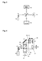
- the optical setup for a color OCT system consists of the following elements: Broad-band light sources 1, 2, 3 are mechanically moved into place, one after the other, and used as the illumination source of an OCT interferometer.
- Such an interferometer consists of a beam splitter 4, partitioning the incoming light beam into a reference beam, reflected by the moving reference mirror 5, and an object beam reflected by the sample 6.
- the beam splitter 4 recombines the light from the two beams, and the interference pattern is sensed with the point photo detector 7.
- the technical realization of this color OCT setup calls for at least four axes of motion, making the resulting system technically complex and costly: The light sources and the reference mirror both must be moved along an axis, and the sample must be moved in the two lateral directions, for the acquisition of a complete volumetric color OCT data set.
- the present invention addresses the problem of the technical complexity of color OCT microscopy according to prior art, and its failure to acquire true-color OCT volumetric images that are perceived by human observers as accurately representing the actual color distribution in the object under study.
- the present invention also addresses the problem of optical absorption in the object under study, which may be depth- as well as wavelength-dependent.
- a principle object of the invention is to provide an optical microscopy technique, capable of acquiring three-dimensional images in their full color as perceived by a human observer, and methods for the realization of easy-to-realize colorimetric three-dimensional microscopy effectively handling absorption and dispersion in the volume under study.
- Another object of the invention is to provide a colorimetric three-dimensional microscopy technique that can be implemented with readily available optoelectronic components, and in such a way that the complete three-dimensional acquisition process can be carried out in fractions of a second or even at video rate (25 to 30 full-color volume images per second).
- a further object of the invention is to provide a colorimetric three-dimensional microscopy technique that can accommodate the presence of locally varying regions of spectrally dependent absorbance or dispersion.
- an interferometric optical setup is employed, using the low temporal coherence of a tunable broad-band light source to resolve the axial dimension, a single opto-mechanical or electronic scanning mechanism for accessing different object depths, and a two-dimensional photo sensor device, capable of demodulating the temporally or spatially modulated scanning signals to reconstruct the object's full volume.
- Three volume scans are carried out sequentially, and the tunable broad-band source is operated in such a way that its spectral distribution for each of the volume scans results in an effective system sensitivity corresponding to one of the three CIE (Commission Internationale d'Éclairage) tristimulus curves, or a linear combination thereof.
- the linear combination of the three volume images then forms the full, true-color volume image for human observers.
- the three-dimensional images can be corrected for spatially- and wavelength-dependent dispersion and absorption effects.
- the colorimetric three-dimensional microscopy system according to the invention is schematically illustrated in Figure 3:
- a tunable light source 10 is used whose emission properties can be electronically controlled to produce different emission spectra S 1 , S 2 and S 3 .
- the tunable light source must be able to produce light in the complete visual wavelength range (approx. 400-700 nm).
- the total effective spectral system response of each of said three emission spectra corresponds to one of the three CIE tristimulus curves shown in Figure 1 (or a linear combination thereof).
- the emission spectrum of the tunable light source 10 must be selected and optimized accordingly.
- a first possible embodiment of such a tunable light source 10 consists of an intense broad-band light source, which is filtered with an electrically or mechanically switchable filter with the above described spectral characteristics.
- Possible embodiments of such light sources include a high-intensity white LED, or a highpressure gas discharge lamp with a sufficiently wide spectrum to cover all visible wavelengths (e.g. metal halide lamps).
- a tunable light source is a monochromatic light source such as a Ti:Sapphire laser system, whose wavelength and intensity are swept at high speed over the desired range, so that an averaged, effective spectrum as described above is obtained.
- the speed of this sweep must be so high that the detector sees a complete spectrum during the time of one fringe period of the OCT signal.
- the light from the light source 10 is coupled into the multi-mode optical fiber 11, and is guided to the input of an optical interferometer, such as a Michelson, a Mach-Zehnder, or a Kösters interferometer.
- the interferometer type used for illustrative purposes in Figure 3 is a Michelson interferometer, consisting of a beam splitter 12, a reference beam path with plane reference mirror 13, an object beam path with the object sample 14, and a two-dimensional image sensor 15, capable of demodulating the OCT signals produced by moving the reference mirror 13 along the reference beam path axis.
- a complete volumetric OCT data set for one selection of light source can therefore be acquired with one scan of the single opto-mechanical scanner that is moving the reference mirror 13. After each scan, the spectrum of the tunable light source is changed, selecting in sequence the three spectral distributions with which the effective spectral system responses that correspond to the CIE tristimulus curves are obtained.
- An alternative, non-mechanical depth-scanning mechanism consists of using a fixed relative position of reference mirror and object, and by realizing the depth scanning through a dispersive optical element and electronic scanning of a one- or two-dimensional image sensor in the photodetector device, as known from FD-OCT, and as described for example by R. A. Leitgeb et al. in "Performance of Fourier domain vs. time domain optical coherence tomography," Optics Express, vol. 11, pp. 889-894, March 2003 .
- a tunable light source 20 is used, whose emission properties can be electrically controlled, in order to produce three emission spectra S 1 , S 2 and S 3 .
- the total spectral system response with these three emission spectra correspond to the three CIE tristimulus curves shown in Figure 1.
- the light from the light source 20 is coupled into a multi-mode optical fiber 21, and the collimating lens 22 converts the emitted light into a parallel beam illuminating an optical interferometer, such as a Michelson interferometer, a Mach-Zehnder interferometer, or a Kösters interferometer.
- the interferometer type used for illustrative purposes in Figure 4 is a Michelson interferometer, consisting of a beam splitter 23, partitioning the impinging source light beam into a reference beam path, and into an object beam path.
- the object beam path contains an object imaging lens 31, focusing the incoming light onto a focal plane 30 on or in the object under study, and collecting the reflected or scattered light from the object plane 30 back into the object beam path.
- a plane deflection mirror 24 redirects the light beam in such a way that it is parallel to the light in the object beam path.
- the light in the reference beam path is then focused by reference imaging lens 27 onto a plane reference mirror 26.
- the reference mirror 26 and the reference imaging lens 27, as well as the object imaging lens 31 in the object beam path are mounted on the same optical subsystem module 25, which can be moved axially by a single opto-mechanical scanner, as indicated by the double arrow.
- the distance from the beam splitter 24 to the reference mirror 26 is equal to the distance from the beam splitter 24 to the object focus plane 30.
- the object imaging lens 31 is identical to the reference imaging lens 27, the geometrical displacement of the measurement focus in the object beam path is equal to the change in optical length in the reference beam path, thus giving the OCT apparatus dynamic coherent focus over the full scanning distance with a single opto-mechanical scanner.
- a compensation plate 28 in the reference beam path on the optical subsystem module 25.
- the properties of this compensation plate are chosen such that it provides for identical thicknesses and refractive properties in the reference as well as in the object beam path.
- the beam splitter 23 recombines the reflected light from the reference beam path and the object beam path to a detection beam path, where the interfering light is focused with an detector imaging lens 33 onto the plane of a image sensor 34.
- the OCT image sensor 34 is capable of demodulating separately for each pixel the incident light, which is temporally modulated according to the axial movement of the optical subsystem module 25.
- the average size of the speckles in the image sensor plane 34 varies as a function of the optical aperture 32 in the detection beam path.
- the average speckle size should be in the range of the effective photosensitive area of the single detector pixels.
- the aperture 32 should be chosen such that the average speckle size has optimum size. Since all components determining the optical magnification of the OCT microscope are contained in the optical subsystem module 25, a different value of the optical magnification can be realized by simply replacing one module 25 for another module 25, having a different set of lenses 31 and 27. All other parts of the OCT microscope according to the present invention are not affected.
- a neutral density plate 29 arranged in the reference beam path can achieve this.
- the transmission ratio of said neutral density plate 29 must be chosen in way that results in optimum signal contrast for different types of objects.
- the different coordinate segments of the depth axis z of the three data sets are adapted to each other, so that the salient signal features in the three measurements coincide, as indicated on the right side of Figure 5.
- the simplest method to carry out this step consists of the following technique:
- the first measurement M 1 is employed as the reference data set.
- the different coordinate sections of the depth axis i.e. the segments between salient points, are stretched or compressed linearly, so as to let the salient signal points of the two measurements M 2 and M 3 with the distorted depth axis coincide with the salient signal points of the reference measurements M 1 .
- an identical depth scan axis for the three measurements can be established, effectively correcting the effect of optical dispersion.
- a further problem of prior art optical microscopy can be successfully addressed by a microscopy system according to the invention:
- a microscopy system In the presence of absorbing layers whose characteristics depend on the wavelength and the depth coordinate, it has not been possible until today to obtain a true-color volumetric representation of a microscopic scene.
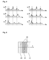
- This problem is illustrated in Figure 6, showing a structure of light absorbing layers 40, 41 and 42 with uniform absorption characteristics, as well as a few reference objects 43 with known spectral reflectance performance:
- Their absolute optical reflectance factors R 1 , R 2 and R 3 for the three illumination spectra S 1 , S 2 and S 3 of the tunable light source are known.
- the light arriving at the depth plane in which these objects lie has been filtered by the multitude of layers on top of the particular object. Thus an unknown amount of the light has been absorbed. The light is reflected by the object, and is transmitted again through the same layers with their unknown absorption characteristics.
- Table 1 Tristimulus curves x, y, z Wavelength [nm] x [a.u.] y [a.u.] z [a.u.] Wavelength [nm] x [a.u.] y [a.u.] z [a.u.] Wavelength [nm] x [a.u.] y [a.u.] z [a.u.] 380 0.001 0.000 0.007 515 0.029 0.608 0.112 650 0.284 0.107 0.000 385 0.002 0.000 0.011 520 0.063 0.710 0.078 655 0.219 0.082 0.000 390 0.004 0.000 0.020 525 0.110 0.793 0.057 660 0.165 0.061 0.000 395 0.008 0.000 0.036 530 0.166 0.862 0.042 665 0.121 0.045 0.000 400 0.014 0.000 0.068 535 0.226 0.915 0.030 670 0.087 0.032
Landscapes
- Physics & Mathematics (AREA)
- General Physics & Mathematics (AREA)
- Chemical & Material Sciences (AREA)
- Optics & Photonics (AREA)
- Analytical Chemistry (AREA)
- Health & Medical Sciences (AREA)
- General Health & Medical Sciences (AREA)
- Multimedia (AREA)
- Engineering & Computer Science (AREA)
- Radiology & Medical Imaging (AREA)
- Nuclear Medicine, Radiotherapy & Molecular Imaging (AREA)
- Computer Vision & Pattern Recognition (AREA)
- Dispersion Chemistry (AREA)
- Life Sciences & Earth Sciences (AREA)
- Biochemistry (AREA)
- Immunology (AREA)
- Pathology (AREA)
- Investigating Or Analysing Materials By Optical Means (AREA)
Applications Claiming Priority (1)
| Application Number | Priority Date | Filing Date | Title |
|---|---|---|---|
| US83942406P | 2006-08-23 | 2006-08-23 |
Publications (2)
| Publication Number | Publication Date |
|---|---|
| EP1892501A2 true EP1892501A2 (fr) | 2008-02-27 |
| EP1892501A3 EP1892501A3 (fr) | 2009-10-07 |
Family
ID=38728869
Family Applications (1)
| Application Number | Title | Priority Date | Filing Date |
|---|---|---|---|
| EP07114610A Withdrawn EP1892501A3 (fr) | 2006-08-23 | 2007-08-20 | Microscopie tridimensionnelle colorimétrique |
Country Status (2)
| Country | Link |
|---|---|
| US (1) | US7659991B2 (fr) |
| EP (1) | EP1892501A3 (fr) |
Cited By (6)
| Publication number | Priority date | Publication date | Assignee | Title |
|---|---|---|---|---|
| US20140226150A1 (en) * | 2013-02-12 | 2014-08-14 | Zygo Corporation | Surface topography interferometer with surface color |
| WO2016003274A1 (fr) | 2014-07-01 | 2016-01-07 | Nederlandse Organisatie Voor Toegepast-Natuurwetenschappelijk Onderzoek Tno | Appareil de microscopie de tomographie par cohérence optique et procédé associé |
| US9255785B2 (en) | 2010-07-08 | 2016-02-09 | Lltech Management | Method and device for high resolution full field interference microscopy |
| CN107743582A (zh) * | 2015-04-10 | 2018-02-27 | Ll技术管理公司 | 用于全场干涉显微成像的方法和系统 |
| KR20190054155A (ko) * | 2016-10-28 | 2019-05-21 | 후지필름 가부시키가이샤 | 광간섭 단층 화상 촬상 장치 및 계측 방법 |
| CN119985479A (zh) * | 2025-04-09 | 2025-05-13 | 中国科学院空间应用工程与技术中心 | 一种射频标记轴向单次快速成像装置及方法 |
Families Citing this family (42)
| Publication number | Priority date | Publication date | Assignee | Title |
|---|---|---|---|---|
| WO2006048163A2 (fr) * | 2004-10-29 | 2006-05-11 | Degudent Gmbh | Procede et dispositif pour saisir des donnees de contours et/ou des proprietes optiques d'un objet tridimensionnel semi-transparent |
| US9125562B2 (en) | 2009-07-01 | 2015-09-08 | Avinger, Inc. | Catheter-based off-axis optical coherence tomography imaging system |
| US8062316B2 (en) | 2008-04-23 | 2011-11-22 | Avinger, Inc. | Catheter system and method for boring through blocked vascular passages |
| US8275226B2 (en) * | 2008-12-09 | 2012-09-25 | Spectral Applied Research Ltd. | Multi-mode fiber optically coupling a radiation source module to a multi-focal confocal microscope |
| WO2010129075A1 (fr) | 2009-04-28 | 2010-11-11 | Avinger, Inc. | Cathéter de support de fil-guide |
| WO2010138927A2 (fr) | 2009-05-28 | 2010-12-02 | Avinger, Inc. | Tomographie par cohérence optique (oct) pour imagerie biologique |
| WO2011003006A2 (fr) | 2009-07-01 | 2011-01-06 | Avinger, Inc. | Cathéter d'athérectomie pourvu d'une pointe déplaçable de manière latérale |
| US9091725B2 (en) * | 2009-07-03 | 2015-07-28 | Koh Young Technology Inc. | Board inspection apparatus and method |
| EP2470886A4 (fr) * | 2009-08-26 | 2016-11-02 | Tomophase Inc | Imagerie optique tissulaire basée sur l'imagerie optique dans le domaine des fréquences |
| US8767216B2 (en) * | 2009-10-13 | 2014-07-01 | California Institute Of Technology | Holographically illuminated imaging devices |
| US8970671B2 (en) * | 2010-02-23 | 2015-03-03 | California Institute Of Technology | Nondiffracting beam detection devices for three-dimensional imaging |
| US11382653B2 (en) | 2010-07-01 | 2022-07-12 | Avinger, Inc. | Atherectomy catheter |
| EP2588012B1 (fr) | 2010-07-01 | 2016-08-17 | Avinger, Inc. | Cathéters d'athérectomie muni de tiges de commande pouvant être déplacées longitudinalement |
| WO2014039096A1 (fr) | 2012-09-06 | 2014-03-13 | Avinger, Inc. | Stylet de réintroduction destiné à un cathéter |
| US9086536B2 (en) | 2011-03-09 | 2015-07-21 | California Institute Of Technology | Talbot imaging devices and systems |
| EP2691038B1 (fr) | 2011-03-28 | 2016-07-20 | Avinger, Inc. | Dispositifs traversant une occlusion, imagerie et dispositifs d'athérectomie |
| US9949754B2 (en) | 2011-03-28 | 2018-04-24 | Avinger, Inc. | Occlusion-crossing devices |
| WO2012145566A2 (fr) | 2011-04-20 | 2012-10-26 | California Institute Of Technology | Dispositifs d'imagerie à éclairement talbot, systèmes et procédés d'ajustement du plan focal |
| EP3653151A1 (fr) | 2011-10-17 | 2020-05-20 | Avinger, Inc. | Cathéters d'athérectomie et mécanisme d'actionnement sans contact pour cathéters |
| US9345406B2 (en) | 2011-11-11 | 2016-05-24 | Avinger, Inc. | Occlusion-crossing devices, atherectomy devices, and imaging |
| WO2013172972A1 (fr) | 2012-05-14 | 2013-11-21 | Avinger, Inc. | Tomographie à cohérence optique ayant une fibre à gradient d'indice pour imagerie biologique |
| WO2013172974A1 (fr) | 2012-05-14 | 2013-11-21 | Avinger, Inc. | Ensembles de pilotage de cathéter d'athérectomie |
| WO2013172970A1 (fr) | 2012-05-14 | 2013-11-21 | Avinger, Inc. | Cathéters d'athérectomie à imagerie |
| US9498247B2 (en) | 2014-02-06 | 2016-11-22 | Avinger, Inc. | Atherectomy catheters and occlusion crossing devices |
| EP2892448B1 (fr) | 2012-09-06 | 2020-07-15 | Avinger, Inc. | Cathéters d'athérectomie à ballon et à système d'imagerie |
| US11284916B2 (en) | 2012-09-06 | 2022-03-29 | Avinger, Inc. | Atherectomy catheters and occlusion crossing devices |
| US11096717B2 (en) | 2013-03-15 | 2021-08-24 | Avinger, Inc. | Tissue collection device for catheter |
| WO2014143064A1 (fr) | 2013-03-15 | 2014-09-18 | Avinger, Inc. | Dispositifs de traversée d'occlusion totale chronique à l'aide d'imagerie |
| US10932670B2 (en) | 2013-03-15 | 2021-03-02 | Avinger, Inc. | Optical pressure sensor assembly |
| WO2014179269A2 (fr) * | 2013-04-30 | 2014-11-06 | Molecular Devices, Llc | Appareil et procédé permettant de générer des images focalisées à l'aide d'une imagerie parallèle dans un système de microscopie |
| JP6517198B2 (ja) | 2013-07-08 | 2019-05-22 | アビンガー・インコーポレイテッドAvinger, Inc. | 介入療法を案内する弾性層の識別 |
| JP6539669B2 (ja) | 2014-02-06 | 2019-07-03 | アビンガー・インコーポレイテッドAvinger, Inc. | 粥腫切除カテーテル及び閉塞横断装置 |
| MX2017000303A (es) | 2014-07-08 | 2017-07-10 | Avinger Inc | Dispositivos para oclusion transversal cronica total de alta velocidad. |
| EP3322338B1 (fr) | 2015-07-13 | 2025-02-12 | Avinger, Inc. | Lentille réflectrice anamorphosante micro-moulée pour cathéters à usage diagnostique/thérapeutique guidés par imagerie |
| CN108882857A (zh) | 2016-01-25 | 2018-11-23 | 阿维格公司 | 具有滞后修正的oct成像导管 |
| JP6959255B2 (ja) | 2016-04-01 | 2021-11-02 | アビンガー・インコーポレイテッドAvinger, Inc. | 粥腫切除用カテーテルデバイス |
| US11344327B2 (en) | 2016-06-03 | 2022-05-31 | Avinger, Inc. | Catheter device with detachable distal end |
| US11224459B2 (en) | 2016-06-30 | 2022-01-18 | Avinger, Inc. | Atherectomy catheter with shapeable distal tip |
| CN106441152B (zh) * | 2016-10-18 | 2019-02-01 | 淮阴师范学院 | 非对称式光学干涉测量方法及装置 |
| EP3538941B1 (fr) | 2016-11-10 | 2025-04-23 | The Trustees of Columbia University in the City of New York | Procédés d'imagerie rapide de grands échantillons à haute résolution |
| US12167867B2 (en) | 2018-04-19 | 2024-12-17 | Avinger, Inc. | Occlusion-crossing devices |
| JP2022553223A (ja) | 2019-10-18 | 2022-12-22 | アビンガー・インコーポレイテッド | 閉塞横断装置 |
Citations (4)
| Publication number | Priority date | Publication date | Assignee | Title |
|---|---|---|---|---|
| US5640270A (en) | 1996-03-11 | 1997-06-17 | Wyko Corporation | Orthogonal-scanning microscope objective for vertical-scanning and phase-shifting interferometry |
| WO2002088705A2 (fr) | 2001-05-01 | 2002-11-07 | The General Hospital Corporation | Procede et appareil pour determiner un type de plaque d'atherosclerose par mesure de proprietes optiques de tissu |
| US20030043381A1 (en) | 2001-06-15 | 2003-03-06 | Carl Zeiss Jena Gmbh | Numerical a posteriori dispersion compensation in PCI measurement signals and OCT A-scan signals with spatially variant correlation core |
| US20050185192A1 (en) | 2004-02-20 | 2005-08-25 | Kim Myung K. | Method of full-color optical coherence tomography |
Family Cites Families (11)
| Publication number | Priority date | Publication date | Assignee | Title |
|---|---|---|---|---|
| US3013467A (en) | 1957-11-07 | 1961-12-19 | Minsky Marvin | Microscopy apparatus |
| US6134003A (en) * | 1991-04-29 | 2000-10-17 | Massachusetts Institute Of Technology | Method and apparatus for performing optical measurements using a fiber optic imaging guidewire, catheter or endoscope |
| US5321501A (en) | 1991-04-29 | 1994-06-14 | Massachusetts Institute Of Technology | Method and apparatus for optical imaging with means for controlling the longitudinal range of the sample |
| US6501551B1 (en) * | 1991-04-29 | 2002-12-31 | Massachusetts Institute Of Technology | Fiber optic imaging endoscope interferometer with at least one faraday rotator |
| US5929999A (en) * | 1998-09-01 | 1999-07-27 | Hewlett-Packard Company | Light source for tristimulus colorimetry |
| US6191862B1 (en) * | 1999-01-20 | 2001-02-20 | Lightlab Imaging, Llc | Methods and apparatus for high speed longitudinal scanning in imaging systems |
| EP1458087B1 (fr) | 2003-03-10 | 2005-10-12 | CSEM Centre Suisse d'Electronique et de Microtechnique SA | Circuit électrique, dispositif et méthode de démodulation d'un signal à modulation d'intensité |
| ES2310744T3 (es) * | 2003-06-06 | 2009-01-16 | The General Hospital Corporation | Fuente de luz sintonizable en longitudes de onda. |
| EP2278287B1 (fr) * | 2003-10-27 | 2016-09-07 | The General Hospital Corporation | Procédé et appareil de l'imagerie optique avec de l'interférométrie dans le domaine de fréquence |
| US7336366B2 (en) * | 2005-01-20 | 2008-02-26 | Duke University | Methods and systems for reducing complex conjugate ambiguity in interferometric data |
| US7468997B2 (en) * | 2006-01-20 | 2008-12-23 | Praevium Research, Inc. | System for swept source optical coherence tomography |
-
2007
- 2007-08-20 EP EP07114610A patent/EP1892501A3/fr not_active Withdrawn
- 2007-08-22 US US11/894,960 patent/US7659991B2/en not_active Expired - Fee Related
Patent Citations (4)
| Publication number | Priority date | Publication date | Assignee | Title |
|---|---|---|---|---|
| US5640270A (en) | 1996-03-11 | 1997-06-17 | Wyko Corporation | Orthogonal-scanning microscope objective for vertical-scanning and phase-shifting interferometry |
| WO2002088705A2 (fr) | 2001-05-01 | 2002-11-07 | The General Hospital Corporation | Procede et appareil pour determiner un type de plaque d'atherosclerose par mesure de proprietes optiques de tissu |
| US20030043381A1 (en) | 2001-06-15 | 2003-03-06 | Carl Zeiss Jena Gmbh | Numerical a posteriori dispersion compensation in PCI measurement signals and OCT A-scan signals with spatially variant correlation core |
| US20050185192A1 (en) | 2004-02-20 | 2005-08-25 | Kim Myung K. | Method of full-color optical coherence tomography |
Cited By (13)
| Publication number | Priority date | Publication date | Assignee | Title |
|---|---|---|---|---|
| US9255785B2 (en) | 2010-07-08 | 2016-02-09 | Lltech Management | Method and device for high resolution full field interference microscopy |
| EP2591389B1 (fr) * | 2010-07-08 | 2018-06-06 | LLtech Management | Procédé et dispositif pour l'imagerie tridimensionnelle par la microscopie interférentielle plein champ |
| US20140226150A1 (en) * | 2013-02-12 | 2014-08-14 | Zygo Corporation | Surface topography interferometer with surface color |
| US9541381B2 (en) * | 2013-02-12 | 2017-01-10 | Zygo Corporation | Surface topography interferometer with surface color |
| WO2016003274A1 (fr) | 2014-07-01 | 2016-01-07 | Nederlandse Organisatie Voor Toegepast-Natuurwetenschappelijk Onderzoek Tno | Appareil de microscopie de tomographie par cohérence optique et procédé associé |
| CN107743582A (zh) * | 2015-04-10 | 2018-02-27 | Ll技术管理公司 | 用于全场干涉显微成像的方法和系统 |
| KR20190054155A (ko) * | 2016-10-28 | 2019-05-21 | 후지필름 가부시키가이샤 | 광간섭 단층 화상 촬상 장치 및 계측 방법 |
| CN109906370A (zh) * | 2016-10-28 | 2019-06-18 | 富士胶片株式会社 | 光学相干断层图像摄像装置及测量方法 |
| EP3534147A4 (fr) * | 2016-10-28 | 2019-09-04 | FUJIFILM Corporation | Dispositif d'imagerie tomographique par cohérence optique et procédé de mesure |
| JPWO2018079326A1 (ja) * | 2016-10-28 | 2019-09-26 | 富士フイルム株式会社 | 光干渉断層画像撮像装置および計測方法 |
| CN109906370B (zh) * | 2016-10-28 | 2021-07-27 | 富士胶片株式会社 | 光学相干断层图像摄像装置及测量方法 |
| US11357403B2 (en) | 2016-10-28 | 2022-06-14 | Fujifilm Corporation | Optical coherence tomography apparatus and measurement method |
| CN119985479A (zh) * | 2025-04-09 | 2025-05-13 | 中国科学院空间应用工程与技术中心 | 一种射频标记轴向单次快速成像装置及方法 |
Also Published As
| Publication number | Publication date |
|---|---|
| US7659991B2 (en) | 2010-02-09 |
| EP1892501A3 (fr) | 2009-10-07 |
| US20080049234A1 (en) | 2008-02-28 |
Similar Documents
| Publication | Publication Date | Title |
|---|---|---|
| US7659991B2 (en) | Colorimetric three-dimensional microscopy | |
| JP5214883B2 (ja) | 三次元分光的符号化撮像のための方法と装置 | |
| KR102048793B1 (ko) | 표면 컬러를 이용한 표면 토포그래피 간섭측정계 | |
| CN108254909B (zh) | 光学显微镜和用于利用光学显微镜记录图像的方法 | |
| US8649024B2 (en) | Non-contact surface characterization using modulated illumination | |
| US7710577B2 (en) | Multiplexing spectrum interference optical coherence tomography | |
| US8619184B2 (en) | Camera adapter based optical imaging apparatus | |
| KR101768050B1 (ko) | 스펙트럼 분석을 위한 분광 기기 및 방법 | |
| US20080024767A1 (en) | Imaging optical coherence tomography with dynamic coherent focus | |
| EP1887312A1 (fr) | Tomographie de cohérence optique d'imagerie avec mise au point cohérente | |
| GB2299235A (en) | Confocal fluorescence microscopy | |
| WO2015177784A2 (fr) | Système permettant la tomographie et/ou des mesures topographiques d'un objet stratifié | |
| TW201800720A (zh) | 光學系統及使用該系統之物體表面或內部光反射介面三維形貌偵測方法 | |
| WO2013105922A2 (fr) | Caractérisation de surface sans contact utilisant un éclairage modulé | |
| US20230160827A1 (en) | Large-field 3d spectral microscopy | |
| CN201328803Y (zh) | 超高分辨率谱域oct的超宽带光谱探测系统 | |
| TW202014671A (zh) | 光學地量測與成像一量測物件的裝置與方法 | |
| US20180252518A1 (en) | Optical profilometer | |
| US20170314914A1 (en) | Optical profilometer | |
| KR101868110B1 (ko) | 소형카메라 통합모듈의 불량 검출 장치 | |
| Lu et al. | Hyperspectral Microscope with Tunable Light Source | |
| CN121548722A (zh) | 用于生成三维物体的3d记录的记录装置及方法 | |
| Fontana et al. | Enriching the metrological toolbox for applications to cultural heritage |
Legal Events
| Date | Code | Title | Description |
|---|---|---|---|
| PUAI | Public reference made under article 153(3) epc to a published international application that has entered the european phase |
Free format text: ORIGINAL CODE: 0009012 |
|
| AK | Designated contracting states |
Kind code of ref document: A2 Designated state(s): AT BE BG CH CY CZ DE DK EE ES FI FR GB GR HU IE IS IT LI LT LU LV MC MT NL PL PT RO SE SI SK TR |
|
| AX | Request for extension of the european patent |
Extension state: AL BA HR MK YU |
|
| PUAL | Search report despatched |
Free format text: ORIGINAL CODE: 0009013 |
|
| AK | Designated contracting states |
Kind code of ref document: A3 Designated state(s): AT BE BG CH CY CZ DE DK EE ES FI FR GB GR HU IE IS IT LI LT LU LV MC MT NL PL PT RO SE SI SK TR |
|
| AX | Request for extension of the european patent |
Extension state: AL BA HR MK RS |
|
| 17P | Request for examination filed |
Effective date: 20091130 |
|
| 17Q | First examination report despatched |
Effective date: 20100104 |
|
| AKX | Designation fees paid |
Designated state(s): AT BE BG CH CY CZ DE DK EE ES FI FR GB GR HU IE IS IT LI LT LU LV MC MT NL PL PT RO SE SI SK TR |
|
| RAP1 | Party data changed (applicant data changed or rights of an application transferred) |
Owner name: HELIOTIS AG |
|
| STAA | Information on the status of an ep patent application or granted ep patent |
Free format text: STATUS: THE APPLICATION IS DEEMED TO BE WITHDRAWN |
|
| 18D | Application deemed to be withdrawn |
Effective date: 20140301 |