EP1892582B1 - Dispositif d'alignement de feuille et appareil de formation d'images comprenant celui-ci - Google Patents
Dispositif d'alignement de feuille et appareil de formation d'images comprenant celui-ci Download PDFInfo
- Publication number
- EP1892582B1 EP1892582B1 EP07114677A EP07114677A EP1892582B1 EP 1892582 B1 EP1892582 B1 EP 1892582B1 EP 07114677 A EP07114677 A EP 07114677A EP 07114677 A EP07114677 A EP 07114677A EP 1892582 B1 EP1892582 B1 EP 1892582B1
- Authority
- EP
- European Patent Office
- Prior art keywords
- sheet
- pair
- rollers
- horizontal registration
- conveying
- Prior art date
- Legal status (The legal status is an assumption and is not a legal conclusion. Google has not performed a legal analysis and makes no representation as to the accuracy of the status listed.)
- Ceased
Links
- 238000011144 upstream manufacturing Methods 0.000 claims description 23
- 238000012937 correction Methods 0.000 claims description 21
- 238000001514 detection method Methods 0.000 claims description 7
- 230000007246 mechanism Effects 0.000 description 32
- 238000012546 transfer Methods 0.000 description 12
- 210000000078 claw Anatomy 0.000 description 10
- 238000010586 diagram Methods 0.000 description 5
- 238000000926 separation method Methods 0.000 description 4
- 230000004907 flux Effects 0.000 description 3
- 238000000034 method Methods 0.000 description 3
- 230000003287 optical effect Effects 0.000 description 2
- 238000005452 bending Methods 0.000 description 1
- 239000000969 carrier Substances 0.000 description 1
- 239000003086 colorant Substances 0.000 description 1
- 230000007423 decrease Effects 0.000 description 1
- 238000013461 design Methods 0.000 description 1
- 238000011161 development Methods 0.000 description 1
- 230000000694 effects Effects 0.000 description 1
- 238000005516 engineering process Methods 0.000 description 1
- 238000004519 manufacturing process Methods 0.000 description 1
- 238000012986 modification Methods 0.000 description 1
- 230000004048 modification Effects 0.000 description 1
Images



Classifications
-
- B—PERFORMING OPERATIONS; TRANSPORTING
- B65—CONVEYING; PACKING; STORING; HANDLING THIN OR FILAMENTARY MATERIAL
- B65H—HANDLING THIN OR FILAMENTARY MATERIAL, e.g. SHEETS, WEBS, CABLES
- B65H9/00—Registering, e.g. orientating, articles; Devices therefor
- B65H9/002—Registering, e.g. orientating, articles; Devices therefor changing orientation of sheet by only controlling movement of the forwarding means, i.e. without the use of stop or register wall
-
- B—PERFORMING OPERATIONS; TRANSPORTING
- B65—CONVEYING; PACKING; STORING; HANDLING THIN OR FILAMENTARY MATERIAL
- B65H—HANDLING THIN OR FILAMENTARY MATERIAL, e.g. SHEETS, WEBS, CABLES
- B65H7/00—Controlling article feeding, separating, pile-advancing, or associated apparatus, to take account of incorrect feeding, absence of articles, or presence of faulty articles
- B65H7/02—Controlling article feeding, separating, pile-advancing, or associated apparatus, to take account of incorrect feeding, absence of articles, or presence of faulty articles by feelers or detectors
-
- B—PERFORMING OPERATIONS; TRANSPORTING
- B65—CONVEYING; PACKING; STORING; HANDLING THIN OR FILAMENTARY MATERIAL
- B65H—HANDLING THIN OR FILAMENTARY MATERIAL, e.g. SHEETS, WEBS, CABLES
- B65H7/00—Controlling article feeding, separating, pile-advancing, or associated apparatus, to take account of incorrect feeding, absence of articles, or presence of faulty articles
- B65H7/02—Controlling article feeding, separating, pile-advancing, or associated apparatus, to take account of incorrect feeding, absence of articles, or presence of faulty articles by feelers or detectors
- B65H7/06—Controlling article feeding, separating, pile-advancing, or associated apparatus, to take account of incorrect feeding, absence of articles, or presence of faulty articles by feelers or detectors responsive to presence of faulty articles or incorrect separation or feed
- B65H7/10—Controlling article feeding, separating, pile-advancing, or associated apparatus, to take account of incorrect feeding, absence of articles, or presence of faulty articles by feelers or detectors responsive to presence of faulty articles or incorrect separation or feed responsive to incorrect side register
-
- B—PERFORMING OPERATIONS; TRANSPORTING
- B65—CONVEYING; PACKING; STORING; HANDLING THIN OR FILAMENTARY MATERIAL
- B65H—HANDLING THIN OR FILAMENTARY MATERIAL, e.g. SHEETS, WEBS, CABLES
- B65H7/00—Controlling article feeding, separating, pile-advancing, or associated apparatus, to take account of incorrect feeding, absence of articles, or presence of faulty articles
- B65H7/20—Controlling associated apparatus
-
- B—PERFORMING OPERATIONS; TRANSPORTING
- B65—CONVEYING; PACKING; STORING; HANDLING THIN OR FILAMENTARY MATERIAL
- B65H—HANDLING THIN OR FILAMENTARY MATERIAL, e.g. SHEETS, WEBS, CABLES
- B65H9/00—Registering, e.g. orientating, articles; Devices therefor
- B65H9/004—Deskewing sheet by abutting against a stop, i.e. producing a buckling of the sheet
-
- B—PERFORMING OPERATIONS; TRANSPORTING
- B65—CONVEYING; PACKING; STORING; HANDLING THIN OR FILAMENTARY MATERIAL
- B65H—HANDLING THIN OR FILAMENTARY MATERIAL, e.g. SHEETS, WEBS, CABLES
- B65H9/00—Registering, e.g. orientating, articles; Devices therefor
- B65H9/06—Movable stops or gauges, e.g. rising and falling front stops
-
- B—PERFORMING OPERATIONS; TRANSPORTING
- B65—CONVEYING; PACKING; STORING; HANDLING THIN OR FILAMENTARY MATERIAL
- B65H—HANDLING THIN OR FILAMENTARY MATERIAL, e.g. SHEETS, WEBS, CABLES
- B65H9/00—Registering, e.g. orientating, articles; Devices therefor
- B65H9/10—Pusher and like movable registers; Pusher or gripper devices which move articles into registered position
- B65H9/103—Pusher and like movable registers; Pusher or gripper devices which move articles into registered position acting by friction or suction on the article for pushing or pulling it into registered position, e.g. against a stop
- B65H9/106—Pusher and like movable registers; Pusher or gripper devices which move articles into registered position acting by friction or suction on the article for pushing or pulling it into registered position, e.g. against a stop using rotary driven elements as part acting on the article
-
- G—PHYSICS
- G03—PHOTOGRAPHY; CINEMATOGRAPHY; ANALOGOUS TECHNIQUES USING WAVES OTHER THAN OPTICAL WAVES; ELECTROGRAPHY; HOLOGRAPHY
- G03G—ELECTROGRAPHY; ELECTROPHOTOGRAPHY; MAGNETOGRAPHY
- G03G15/00—Apparatus for electrographic processes using a charge pattern
- G03G15/65—Apparatus which relate to the handling of copy material
- G03G15/6555—Handling of sheet copy material taking place in a specific part of the copy material feeding path
- G03G15/6558—Feeding path after the copy sheet preparation and up to the transfer point, e.g. registering; Deskewing; Correct timing of sheet feeding to the transfer point
-
- G—PHYSICS
- G03—PHOTOGRAPHY; CINEMATOGRAPHY; ANALOGOUS TECHNIQUES USING WAVES OTHER THAN OPTICAL WAVES; ELECTROGRAPHY; HOLOGRAPHY
- G03G—ELECTROGRAPHY; ELECTROPHOTOGRAPHY; MAGNETOGRAPHY
- G03G15/00—Apparatus for electrographic processes using a charge pattern
- G03G15/65—Apparatus which relate to the handling of copy material
- G03G15/6555—Handling of sheet copy material taking place in a specific part of the copy material feeding path
- G03G15/6558—Feeding path after the copy sheet preparation and up to the transfer point, e.g. registering; Deskewing; Correct timing of sheet feeding to the transfer point
- G03G15/6561—Feeding path after the copy sheet preparation and up to the transfer point, e.g. registering; Deskewing; Correct timing of sheet feeding to the transfer point for sheet registration
- G03G15/6564—Feeding path after the copy sheet preparation and up to the transfer point, e.g. registering; Deskewing; Correct timing of sheet feeding to the transfer point for sheet registration with correct timing of sheet feeding
-
- G—PHYSICS
- G03—PHOTOGRAPHY; CINEMATOGRAPHY; ANALOGOUS TECHNIQUES USING WAVES OTHER THAN OPTICAL WAVES; ELECTROGRAPHY; HOLOGRAPHY
- G03G—ELECTROGRAPHY; ELECTROPHOTOGRAPHY; MAGNETOGRAPHY
- G03G15/00—Apparatus for electrographic processes using a charge pattern
- G03G15/65—Apparatus which relate to the handling of copy material
- G03G15/6555—Handling of sheet copy material taking place in a specific part of the copy material feeding path
- G03G15/6558—Feeding path after the copy sheet preparation and up to the transfer point, e.g. registering; Deskewing; Correct timing of sheet feeding to the transfer point
- G03G15/6567—Feeding path after the copy sheet preparation and up to the transfer point, e.g. registering; Deskewing; Correct timing of sheet feeding to the transfer point for deskewing or aligning
-
- B—PERFORMING OPERATIONS; TRANSPORTING
- B65—CONVEYING; PACKING; STORING; HANDLING THIN OR FILAMENTARY MATERIAL
- B65H—HANDLING THIN OR FILAMENTARY MATERIAL, e.g. SHEETS, WEBS, CABLES
- B65H2220/00—Function indicators
- B65H2220/09—Function indicators indicating that several of an entity are present
-
- B—PERFORMING OPERATIONS; TRANSPORTING
- B65—CONVEYING; PACKING; STORING; HANDLING THIN OR FILAMENTARY MATERIAL
- B65H—HANDLING THIN OR FILAMENTARY MATERIAL, e.g. SHEETS, WEBS, CABLES
- B65H2301/00—Handling processes for sheets or webs
- B65H2301/30—Orientation, displacement, position of the handled material
- B65H2301/33—Modifying, selecting, changing orientation
- B65H2301/331—Skewing, correcting skew, i.e. changing slightly orientation of material
-
- B—PERFORMING OPERATIONS; TRANSPORTING
- B65—CONVEYING; PACKING; STORING; HANDLING THIN OR FILAMENTARY MATERIAL
- B65H—HANDLING THIN OR FILAMENTARY MATERIAL, e.g. SHEETS, WEBS, CABLES
- B65H2404/00—Parts for transporting or guiding the handled material
- B65H2404/10—Rollers
- B65H2404/14—Roller pairs
-
- B—PERFORMING OPERATIONS; TRANSPORTING
- B65—CONVEYING; PACKING; STORING; HANDLING THIN OR FILAMENTARY MATERIAL
- B65H—HANDLING THIN OR FILAMENTARY MATERIAL, e.g. SHEETS, WEBS, CABLES
- B65H2404/00—Parts for transporting or guiding the handled material
- B65H2404/10—Rollers
- B65H2404/14—Roller pairs
- B65H2404/142—Roller pairs arranged on movable frame
- B65H2404/1424—Roller pairs arranged on movable frame moving in parallel to their axis
-
- B—PERFORMING OPERATIONS; TRANSPORTING
- B65—CONVEYING; PACKING; STORING; HANDLING THIN OR FILAMENTARY MATERIAL
- B65H—HANDLING THIN OR FILAMENTARY MATERIAL, e.g. SHEETS, WEBS, CABLES
- B65H2404/00—Parts for transporting or guiding the handled material
- B65H2404/10—Rollers
- B65H2404/14—Roller pairs
- B65H2404/144—Roller pairs with relative movement of the rollers to / from each other
- B65H2404/1442—Tripping arrangements
-
- B—PERFORMING OPERATIONS; TRANSPORTING
- B65—CONVEYING; PACKING; STORING; HANDLING THIN OR FILAMENTARY MATERIAL
- B65H—HANDLING THIN OR FILAMENTARY MATERIAL, e.g. SHEETS, WEBS, CABLES
- B65H2404/00—Parts for transporting or guiding the handled material
- B65H2404/10—Rollers
- B65H2404/15—Roller assembly, particular roller arrangement
- B65H2404/152—Arrangement of roller on a movable frame
- B65H2404/1523—Arrangement of roller on a movable frame moving in parallel to its axis
-
- B—PERFORMING OPERATIONS; TRANSPORTING
- B65—CONVEYING; PACKING; STORING; HANDLING THIN OR FILAMENTARY MATERIAL
- B65H—HANDLING THIN OR FILAMENTARY MATERIAL, e.g. SHEETS, WEBS, CABLES
- B65H2511/00—Dimensions; Position; Numbers; Identification; Occurrences
- B65H2511/20—Location in space
-
- B—PERFORMING OPERATIONS; TRANSPORTING
- B65—CONVEYING; PACKING; STORING; HANDLING THIN OR FILAMENTARY MATERIAL
- B65H—HANDLING THIN OR FILAMENTARY MATERIAL, e.g. SHEETS, WEBS, CABLES
- B65H2511/00—Dimensions; Position; Numbers; Identification; Occurrences
- B65H2511/20—Location in space
- B65H2511/22—Distance
- B65H2511/222—Stroke
-
- B—PERFORMING OPERATIONS; TRANSPORTING
- B65—CONVEYING; PACKING; STORING; HANDLING THIN OR FILAMENTARY MATERIAL
- B65H—HANDLING THIN OR FILAMENTARY MATERIAL, e.g. SHEETS, WEBS, CABLES
- B65H2511/00—Dimensions; Position; Numbers; Identification; Occurrences
- B65H2511/20—Location in space
- B65H2511/24—Irregularities, e.g. in orientation or skewness
-
- B—PERFORMING OPERATIONS; TRANSPORTING
- B65—CONVEYING; PACKING; STORING; HANDLING THIN OR FILAMENTARY MATERIAL
- B65H—HANDLING THIN OR FILAMENTARY MATERIAL, e.g. SHEETS, WEBS, CABLES
- B65H2511/00—Dimensions; Position; Numbers; Identification; Occurrences
- B65H2511/50—Occurence
- B65H2511/51—Presence
- B65H2511/514—Particular portion of element
-
- B—PERFORMING OPERATIONS; TRANSPORTING
- B65—CONVEYING; PACKING; STORING; HANDLING THIN OR FILAMENTARY MATERIAL
- B65H—HANDLING THIN OR FILAMENTARY MATERIAL, e.g. SHEETS, WEBS, CABLES
- B65H2701/00—Handled material; Storage means
- B65H2701/10—Handled articles or webs
- B65H2701/13—Parts concerned of the handled material
- B65H2701/131—Edges
- B65H2701/1315—Edges side edges, i.e. regarded in context of transport
-
- B—PERFORMING OPERATIONS; TRANSPORTING
- B65—CONVEYING; PACKING; STORING; HANDLING THIN OR FILAMENTARY MATERIAL
- B65H—HANDLING THIN OR FILAMENTARY MATERIAL, e.g. SHEETS, WEBS, CABLES
- B65H9/00—Registering, e.g. orientating, articles; Devices therefor
- B65H9/10—Pusher and like movable registers; Pusher or gripper devices which move articles into registered position
-
- G—PHYSICS
- G03—PHOTOGRAPHY; CINEMATOGRAPHY; ANALOGOUS TECHNIQUES USING WAVES OTHER THAN OPTICAL WAVES; ELECTROGRAPHY; HOLOGRAPHY
- G03G—ELECTROGRAPHY; ELECTROPHOTOGRAPHY; MAGNETOGRAPHY
- G03G2215/00—Apparatus for electrophotographic processes
- G03G2215/00362—Apparatus for electrophotographic processes relating to the copy medium handling
- G03G2215/00535—Stable handling of copy medium
- G03G2215/00717—Detection of physical properties
- G03G2215/00721—Detection of physical properties of sheet position
Definitions
- the present invention relates generally to sheet conveying mechanisms in electrophotographic image forming apparatuses, and more particularly to improving precision in correcting the sheet position in the main scanning direction and correcting a skewed condition of a sheet.
- a sheet aligning device having the features of the preamble of claim 1 is known from US-A-2002/0076250 .
- sheets such as transfer sheets stacked on a sheet feeder are conveyed one by one. Then, a toner image formed on a photoconductive drum or a photoconductive belt is transferred onto each sheet at a transfer position. Finally, the toner image is fixed onto the sheet, thereby obtaining a recorded sheet.
- a registration mechanism including a stopper and a pair of rollers is provided just before the transfer position.
- the registration mechanism corrects the position of a sheet so that the toner image is transferred onto the correct position.
- the stopper is provided on the sheet conveyance path, which stopper determines the position of a sheet in a direction perpendicular to the sheet conveying direction.
- the leading edge of a sheet abuts the stopper, and while the leading edge is being stopped, a conveying unit positioned on the upstream side conveys the sheet, so that the sheet forms a loop.
- the stopper is released, so that the leading edge of the sheet is nipped and conveyed by the pair of rollers situated downstream of the stopper.
- a detecting unit is arranged near a downstream position of the stopper for detecting side portions of the sheet.
- a moving unit includes a pair of rollers that is movable in a direction orthogonal to the sheet conveying direction. The detecting unit and the moving unit function to correct the sheet position so that the sheet is positioned along a sheet scanning reference position (see, for example, Patent Document 1).
- FIG. 7 is a schematic diagram of a conventional sheet conveying mechanism.
- the reference numeral 32 denotes a pair of horizontal registration rollers
- 33 denotes a stopper
- 34 denotes a pair of feed rollers
- 35 denotes a sheet edge detecting sensor
- 36 denotes a pair of conveying rollers
- 37 and 38 denote sheet conveyance paths
- 39 denotes a sheet
- 40 and 41 denote sheet trays
- C denotes a buffer
- D denotes a sheet conveyance path junction.
- the stopper 33 is arranged at a stage immediately before the pair of horizontal registration rollers 32.
- the stopper can be switched between a position for closing the sheet conveyance path and a position for opening the sheet conveyance path.
- the sheet conveyance path is configured in such a manner that the distance between the pair of horizontal registration rollers 32 and the pair of feed rollers 34 is wide enough for a small-sized sheet to be conveyed.
- there are two sheet conveyance paths at the stage before the pair of feed rollers 34 i.e., the conveyance path 38 extending from the sheet tray 40 provided in the main unit of an image forming apparatus (e.g., a printer) and the conveyance path 37 extending from the sheet tray 41 outside the image forming apparatus.
- Each of these conveyance paths 37 and 38 is provided with one of the pairs of conveying rollers 36 for sending the sheet 39 toward the pair of feed rollers 34. Furthermore, these two conveyance paths 37 and 38 merge at the junction D located on the upstream side of the pair of feed rollers 34.
- the sheet 39 being conveyed by the pair of feed rollers 34 is stopped as the leading edge of the sheet 39 abuts the stopper 33, which stopper 33 is previously situated at a position for closing the sheet conveyance path. At this point, the leading edge of the sheet 39 abuts along the stopper 33, and therefore, a skewed condition of the sheet 39 is corrected. Then, the pair of feed rollers 34 conveys the sheet 39 for a certain amount of time, so that the buffer C is formed between the stopper 33 and the pair of feed rollers 34. Subsequently, the stopper 33 is lowered, thus releasing the leading edge of the sheet 39 from the stopped status.
- the leading edge of the sheet 39 is forced to stick out and wedge into the nip portion of the pair of horizontal registration rollers 32.
- the sheet 39 is released from the nip of the pair of feed rollers 34, a position of the edge (side edge) of the sheet 39 in the sheet main scanning direction is detected by the sheet edge detecting sensor 35, and the correction amount in the sheet main scanning direction is calculated.
- the pair of horizontal registration rollers 32 is caused to horizontally move in the roller axial direction in accordance with the calculated correction amount. Accordingly, by performing the operation of correcting the sheet position in the main scanning direction (horizontal registration) with the pair of horizontal registration rollers 32, it is possible to align the position of the sheet 39 with the main scanning direction without affecting the pair of feed rollers 34.
- the following situation may occur. That is, the trailing edge of the sheet 39 may still be sandwiched (held with pressure) by the pair of conveying rollers 36 when the leading edge of the sheet 39 has wedged into the nip portion of the pair of horizontal registration rollers 32. In such a condition, if the pair of horizontal registration rollers 32 is horizontally moved to correct the sheet position in the main scanning direction, the nip portion of the pair of conveying rollers 36 will act as a resistance.
- the sheet 39 may become twisted and wrinkled, or the skew of the sheet 39 that has been corrected at the stopper 33 may reappear. For these reasons, in this case, the nip portion of the pair of conveying rollers 36 is opened.
- both the stopper and the conveying unit need to be provided with a driving unit, which leads to an increase in the size of the apparatus as well as higher manufacturing costs.
- the present invention provides a sheet aligning device according to claim 1 and an image forming apparatus according to claim 5 in which one or more of the above-described disadvantages are eliminated.
- a preferred embodiment of the present invention provides a sheet aligning device and an image forming apparatus in which a sheet conveyed in a skewed condition is precisely corrected before being sent to a transfer position under various conditions.
- a preferred embodiment of the present invention provides a sheet conveying mechanism including plural sheet conveyance paths extending in different manners and a junction of the sheet conveyance paths.
- the sheet conveyance paths are provided on an upstream side of a sheet aligning mechanism unit.
- An embodiment of the present invention provides an image forming apparatus including a sheet conveyance path; at least one pair of conveying rollers; a pair of feed rollers; a pair of horizontal registration rollers; a stopper configured to correct a skewed condition of a sheet being conveyed in the sheet conveyance path and to open/close in such a manner as to allow/prevent passage of the sheet through the sheet conveyance path; and a detecting unit configured to detect a position of a side edge of the sheet, wherein the pair of conveying rollers, the pair of feed rollers, the pair of horizontal registration rollers, the stopper, and the detecting unit are provided along the sheet conveyance path in the stated order starting from an upstream side of a sheet conveyance direction; and the rollers of each of the pair of conveying rollers, the pair of feed rollers, and the pair of horizontal registration rollers are configured to come in contact with/separate from each other, the image forming apparatus further including a control unit configured to perform horizontal registration correction while the pair of horizontal registration rollers
- a sheet aligning device and an image forming apparatus which include a mechanism for precisely positioning the leading edge of the sheet before the sheet is sent to a transfer position. Paper jams are prevented and the leading edge of the sheet is prevented from bending in a registration unit of the mechanism.
- the mechanism can be manufactured at low cost.
- a pair of sheet conveying rollers is positioned on the upstream side of a junction of sheet conveyance paths, and the sheet conveying rollers can be separated from each other.
- the sheet conveyance paths extend in a straight manner or in a curved manner with a curvature radius of 50 mm or more. Accordingly, regardless of the length or thickness of the sheet, it is possible to reduce the resistance applied to the sheet while aligning the sheet conveyance position with the main scanning direction in the sheet aligning mechanism. Consequently, the sheet aligning mechanism can align the sheet conveyance position with high precision.
- FIG. 1 illustrates an example of a sheet conveying mechanism according to an embodiment of the present invention.
- the reference numeral 1 denotes a sheet aligning mechanism
- 2 denotes at least one pair of horizontal registration rollers acting as the first pair of rollers
- 3 denotes a stopper with a claw portion on one end
- 4 denotes at least one pair of feed rollers acting as the second pair of rollers
- 5 denotes a detecting sensor
- 6 denotes pairs of conveying rollers acting as the third pairs of rollers
- 7 denotes a straight sheet conveyance path
- 8 denotes a curved sheet conveyance path
- 9 denotes a sheet
- 10 and 11 denote sheet trays
- A denotes a sheet conveyance path junction
- B denotes a buffer.
- the curved sheet conveyance path 8 extending from the sheet tray 10 provided in the main unit of an image forming apparatus and the straight sheet conveyance path 7 extending from the sheet tray 11 outside the image forming apparatus.
- Each of these conveyance paths 7 and 8 is provided with the pairs of conveying rollers 6 for sending the sheet 9 toward the pair of feed rollers 4.
- the distance between adjacent pairs of conveying rollers 6 is 150 mm through 180 mm, so that a small-sized sheet can be conveyed.
- one roller acts as a driving roller and the other roller acts as a following roller, and the driving roller and the following roller can be separated from each other.
- the straight sheet conveyance path 7 and the curved sheet conveyance path 8 merge at the junction A located upstream of the pair of feed rollers 4.
- the sheet aligning mechanism 1 includes the pair of horizontal registration rollers 2, the stopper 3, the pair of feed rollers 4, and the detecting sensor 5 including a CIS sensor, a CCD linear image sensor, etc., for detecting the side edge of the sheet 9.
- the conveyance path between the pair of horizontal registration rollers 2 and the pair of feed rollers 4 has a distance of 100 mm through 180 mm and has a substantially straight shape so that a small-sized sheet can be conveyed therethrough.
- the stopper 3 is arranged immediately downstream of the pair of horizontal registration rollers 2. The stopper 3 can be switched between a position for closing the sheet conveyance path and a position for opening the sheet conveyance path.
- the stopper 3 is lowered to release the leading edge of the sheet 9 and the rollers of the pair of feed rollers 4 are separated from each other.
- the sheet 9 is conveyed by the pair of horizontal registration rollers 2.
- the detecting sensor 5 detects the edge position of the sheet 9 in the main scanning direction.
- a not shown control unit calculates the correction amount of the sheet 9 in the main scanning direction.
- the control unit causes the pair of horizontal registration rollers 2 to horizontally move in the roller axial direction in accordance with the calculated correction amount. Accordingly, the position of the sheet 9 is aligned with the main scanning direction and the operation of correcting the sheet position is completed. Even during the horizontal movement, the horizontal registration rollers 2 rotate in order to keep conveying the sheet 9. Thus, it is possible to minimize wasted time.
- a sheet conveying device e.g., a transfer unit
- rollers arranged on the downstream side of the pair of horizontal registration rollers 2 the rollers of the pair of horizontal registration rollers 2 are separated from each other once again, to be returned to a home position (described below).
- control unit controls at least the pair(s) conveying rollers 6 over which the sheet extends in such a manner that the conveying rollers 6 are separated from each other.
- the sheet 9 is only held by the pair of horizontal registration rollers 2 regardless of the length of the sheet. Therefore, the only resistance applied to the sheet 9 on the upstream side of the pair of horizontal registration rollers 2 is the friction between the sheet 9 and the sheet conveyance path.
- the sheet conveyance path of the sheet aligning mechanism 1 is straight, and therefore, it is possible to minimize the conveyance resistance applied to the sheet 9 while the sheet conveying position is being aligned by the pair of horizontal registration rollers 2.
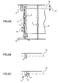
- FIGS. 2A through 2C are top views of a sheet aligning device according to an embodiment of the present invention.
- FIG. 2A is a partial schematic diagram of an example employing a linear sensor
- FIG. 2B is a partial view of an example employing one photo-coupler
- FIG. 2C is a partial view of an example employing two photo-couplers.
- the reference numeral 12 denotes a unit frame
- 13 denotes a spring
- 14 denotes a cam
- 15 denotes an arrow indicating the direction in which the sheet 9 is moved
- 16 denotes a sheet conveyance reference position
- 17 denotes the shift amount of the position of the sheet side edge.
- the detecting sensor 5 for detecting the sheet side edge position is arranged downstream of the stopper 3.
- the pair of horizontal registration rollers 2 is joined to the unit frame 12, and is configured to be moved in its axial direction by a horizontal movement unit.
- the horizontal movement unit includes the unit frame 12, the spring 13, the cam 14 having a rotational axis provided in the main unit of the image forming apparatus, and a not shown driving source that rotationally drives the cam 14.
- the unit frame 12 is constantly pressed against the cam 14 by the spring 13. By the rotation of the cam 14, the unit frame 12 can be moved in a direction (the direction indicated by the arrow 15) perpendicular to the sheet conveyance direction, that is, the axial direction of the pair of horizontal registration rollers 2.
- the cam 14 rotates to correct the position of the sheet 9 by an amount corresponding to the shift amount 17 so that the sheet side edge is aligned with the predetermined sheet conveyance reference position 16.
- the shift amount of the sheet side edge from the reference position can be easily measured with the conventional technology.
- This shift amount is converted into the rotation amount of the cam 14 so that the cam 14 rotates by an amount corresponding to the correction amount.
- the measured value is output as a discrete value with respect to the length; however, no problems should arise as long as the length corresponding to one bit of the pixel of the CCD array (distance in the shift direction of the side edge) is less than or equal to the allowable error of sheet alignment.
- the horizontal shift amount of the sheet 9 cannot be directly calculated. However, the direction in which the sheet 9 is shifted can be detected. Therefore, the horizontal position of the sheet 9 can be controlled by directly feeding back the output of the photo-coupler to the control unit that controls the cam 14.
- the sheet 9 is once again horizontally moved in a direction toward a position where an output can be obtained.
- the horizontal movement is stopped.
- a stopping error may only be caused by the stopping error of the motor rotating the cam 14 and the error in the time taken by a stop command to reach the cam 14.
- One option is to stop the movement as soon as the output is obtained in both the first and second cases and another option is to stop the movement as soon as the output is turned off in both the first and second cases. Either option can be chosen according to the design of the sheet aligning device.
- the cam 14 is controlled by the control unit to stay at a home position where minimal horizontal movement is caused under regular conditions, i.e., when the sheet 9 is conveyed along the sheet conveyance reference position 16.
- the control unit causes the cam 14 to return to its original position, i.e., the home position.
- the detection positions of the two photo-couplers are arranged to be opposite to each other across the sheet conveyance reference position 16. The distance between the two detection positions approximately corresponds to the allowable error of horizontal registration.
- the photo-coupler A is arranged on the side closer to the sheet center with respect to the sheet conveyance reference position 16. If an output cannot be obtained from the photo-coupler A as light flux is blocked by the sheet 9 but an output can be obtained from the photo-coupler B, the side edge of the sheet 9 is at a desirable position.
- the side edge of the sheet 9 is horizontally shifted. Accordingly, the shift can be corrected by moving the sheet 9 in corresponding directions, until the output of the photo-coupler A is turned off in the former case, and until the output of the photo-coupler B is obtained in the latter case.
- FIG. 3 is a side view of the sheet aligning device according to an embodiment of the present invention.
- the reference numerals 18, 19, and 20 denote springs
- 21 denotes a camshaft
- 22, 23, and 24 denote cams
- 25 denotes a spindle of the stopper 3
- 26 denotes a retract arm for moving together/apart the horizontal registration rollers 2
- 27 denotes a spindle of the retract arm
- 28 denotes a retract arm for moving together/apart the feed rollers 4
- 29 denotes a spindle of the retract arm 28
- 30 denotes a sheet conveyance path.
- the stopper 3 is rotatable about the spindle 25, and is caused to protrude into the sheet conveyance path 30 by the spring 19.
- the stopper 3 is configured to open the sheet conveyance path 30 by being moved by the cam 23.
- the primary parts of the sheet aligning device are first and second conveying units.
- the first conveying unit includes the pair of horizontal registration rollers 2, a driving mechanism, and a contact/separation mechanism thereof.
- the second conveying unit includes the pair of feed rollers 4, a driving mechanism, and a contact/separation mechanism thereof.
- the pair of horizontal registration rollers 2 is arranged upstream of the stopper 3, and the rollers of the pair of horizontal registration rollers 2 are pressed against each other by the spring 18.
- the rollers of the pair of horizontal registration rollers 2 can be separated from each other as the retract arm 26 (hereinafter, simply referred to as "arm 26") rotatable about the spindle 27 is pushed up by the cam 22.
- the rollers of the pair of feed rollers 4 are also pushed against each other by the spring 20.
- the rollers of the pair of feed rollers 4 can be separated from each other as the retract arm 28 (hereinafter, simply referred to as "arm 28") rotatable about the spindle 29 is pushed up by the cam 24.
- the cam 22, the cam 23, and the cam 24 are fixed along the same shaft, i.e., the camshaft 21.
- the cam 22, the cam 23, and the cam 24 perform the following operations in combination, i.e., contact/separation of the pair of horizontal registration rollers 2, opening/closing of the sheet conveying path 30 by the stopper 3, and contact/separation of the pair of feed rollers 4.
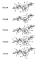
- FIGS. 4A through 4E are schematic diagrams illustrating operations according to an embodiment of the present invention.
- FIG. 4A illustrates a status where the horizontal registration rollers 2 are open (separated).
- FIG. 4B illustrates a status where none of the cams are operating.
- FIG. 4C illustrates a status where the stopper 3 and the feed rollers 4 are open.
- FIG. 4D illustrates a status where the stopper 3, the feed rollers 4, and the horizontal registration rollers 2 are open.
- FIG. 4E illustrates a status where the horizontal registration rollers 2 are open.
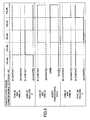
- FIG. 5 is a timing chart of the operation of the mechanism illustrated in FIGS. 4A through 4E .
- the thick dashed line indicates the status of a cam and its corresponding member.
- IN CONTACT indicates that the corresponding elements are in contact (or operating) and "SEPARATED” indicates the corresponding elements are separated (or opened).
- OPEN indicates that the sheet conveying path 30 is open and "CLOSED” indicates that the sheet conveying path 30 is closed.
- the regions corresponding to FIGS. 4A through 4E have equal sizes in the horizontal direction as a matter of convenience. However, these sizes do not represent the actual region of the rotational angle of the camshaft 21 corresponding to the respective statuses.
- FIGS. 4A through 4E The operation of the mechanism illustrated in FIGS. 4A through 4E is described with reference to FIG. 5 .
- the stopper 3 is protruding into the sheet conveyance path 30.
- the horizontal registration rollers 2 are separated from each other as the cam 22 is in contact with the arm 26 to press up one of the rollers against the force of the spring 18.
- the feed rollers 4 are pressed against each other and are sandwiching the sheet 9. Due to the rotation of the pair of feed rollers 4, the sheet 9 is conveyed at a prescribed speed. When the leading edge of the sheet 9 reaches a position immediately before the stopper 3, the conveyance speed is reduced, and then the leading edge of the sheet 9 abuts the stopper 3. Further, the sheet 9 is pushed in the sheet conveyance direction by the pair of feed rollers 4. When a loop 9a is formed in the sheet 9, the pair of feed rollers 4 stops rotating. At this point, due to the force of the loop 9a, the leading edge of the sheet 9a collides with the stopper 3, so that the skewed condition of the sheet 9 is corrected.
- the cam 14 causes the pair of horizontal registration rollers 2 to move in the direction indicated by the arrow 15 while sandwiching and conveying the sheet 9 so that the sheet edge comes to the sheet conveyance reference position 16.
- FIG. 4D when the sheet 9 has reached a not shown sheet conveying unit positioned on the downstream side or an image transfer position, the camshaft 21 rotates so that the cam 22 causes the horizontal registration rollers 2 to be separated. Subsequently, the cam 14 shown in FIG. 2A rotates further or rotates in a reverse direction so that the horizontal registration rollers 2 move in a direction opposite to the direction in which they moved in the status shown in FIG. 4C and return to the home position. At this point, the horizontal registration rollers 2 are still separated, and therefore, even if the middle of the sheet 9 is situated directly beneath the horizontal registration rollers 2, the behavior of the sheet 9 is unaffected.
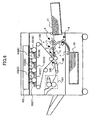
- FIG. 6 illustrates an example of an image forming apparatus to which an embodiment of the present invention is applied.
- the reference numeral 101 denotes photoconductors acting as image carriers
- 102 denotes an optical writing device
- 103 denotes developing devices
- 104 denotes a transfer belt
- 106 denotes a conveying device
- 107 denotes a fixing device
- Y, C, M, and K respectively denote yellow, cyan, magenta, and black, which are development colors.
- the optical writing device 102 forms latent images on the photoconductors 101, the developing devices 103 turn the latent images into visible images, and the images are then transferred onto the transfer belt 104.
- a sheet P supplied from the sheet tray 10 is conveyed by the pair of conveying rollers 6 provided on the curved sheet conveyance path 8 to the pair of feed rollers 4.
- the pair of feed rollers 4 conveys the sheet P so that the leading edge of the sheet P abuts the claw portion of the stopper 3 inserted into the sheet conveyance path.
- the pair of conveying rollers 6 provided on the straight sheet conveyance path 7 conveys the sheet P to the pair of feed rollers 4, and similar operations follow.
- the horizontal registration rollers 2 are open. After a skewed condition of the sheet P is corrected as the leading edge of the sheet P abuts the stopper 3, the horizontal registration rollers 2 sandwich the sheet P. Then, the stopper 3 retreats from the sheet conveyance path and the feed rollers 4 separate from each other. While conveying the sheet P, the horizontal registration rollers 2 move horizontally in accordance with output from a not shown detecting sensor to perform horizontal registration correction. The speed of horizontal movement is determined so that the correction is completed by the time the leading edge of the sheet P reaches a secondary transfer device 105. When the leading edge of the sheet P is nipped by the secondary transfer device 105, the horizontal registration rollers 2 open.
- the sheet P After the image is transferred onto the sheet P from the transfer belt 104, the sheet P is conveyed by the conveying device 106 to the fixing device 107. After the image is fixed onto the sheet P, the sheet P is ejected outside the main unit of the image forming apparatus.
- the curved sheet conveyance path 8 By making the curved sheet conveyance path 8 have a large curvature radius of 50 mm or more, it is possible to reduce the resistance applied to the sheet 9 in the curved sheet conveyance path 8. As a result, in a case where the sheet 9 is longer than the distance between the stopper 3 and the sheet conveyance path junction A, is thick, has body, and thus generates a large conveyance resistance; this sheet 9 is conveyed via the curved sheet conveyance path 8 to the sheet aligning mechanism 1; and the pair of horizontal registration rollers 2 aligns the conveyance position of the sheet 9, the following effects are achieved.
- An embodiment of the present invention has been described by taking as an example a sheet aligning device in a sheet feeding device of an image forming apparatus; however, it is obvious that an embodiment of the present invention is applicable to any general-use printer for preventing a skewed condition or horizontal shifts of a sheet being conveyed.
- a sheet aligning device includes a sheet conveyance path; a detecting unit configured to detect a side edge of a sheet being conveyed in the sheet conveyance path; a stopper provided on an upstream side of the detecting unit and configured to open/close in such a manner as to allow/prevent passage of the sheet through the sheet conveyance path and to position a leading edge of the sheet being conveyed in the sheet conveyance path; a first conveying unit provided on an upstream side of the stopper, the first conveying unit including a pair of first rollers configured to come in contact with/separate from each other; a second conveying unit provided on an upstream side of the first conveying unit, the second conveying unit including a pair of second rollers configured to come in contact with/separate from each other; and a horizontal movement unit configured to move the pair of first rollers in an axial direction of the first rollers based on a detection result output by the detecting unit.
- the second conveying unit conveys the sheet in such a manner that the sheet forms a loop between the stopper and the second conveying unit; after the loop is formed, the first rollers come in contact together, the stopper opens, the second rollers are separated from each other, and while the sheet is being conveyed by the first rollers, the horizontal movement unit moves the first rollers in the axial direction of the first rollers; and after the sheet has passed through the first conveying unit, the horizontal movement unit returns the pair of first rollers to an original position.
- a conveyance speed of the second conveying unit is temporarily reduced when the sheet abuts the stopper.
- operations of opening/closing the stopper, causing the first rollers to come in contact with/separate from each other, and causing the second rollers to come in contact with/separate from each other, are performed in conjunction with each other by a single driving source.
- the operations of opening/closing the stopper, causing the first rollers to come in contact with/separate from each other, and causing the second rollers to come in contact with/separate from each other, are performed by three cams that are fixed to the same camshaft.
- an image forming apparatus includes the sheet aligning device according to one embodiment of the present invention.
- an image forming apparatus includes a sheet conveyance path; at least one pair of conveying rollers; a pair of feed rollers; a pair of horizontal registration rollers; a stopper configured to correct a skewed condition of a sheet being conveyed in the sheet conveyance path and to open/close in such a manner as to allow/prevent passage of the sheet through the sheet conveyance path; and a detecting unit configured to detect a position of a side edge of the sheet, wherein the pair of conveying rollers, the pair of feed rollers, the pair of horizontal registration rollers, the stopper, and the detecting unit are provided along the sheet conveyance path in the stated order starting from an upstream side of a sheet conveyance direction; and the rollers of each of the pair of conveying rollers, the pair of feed rollers, and the pair of horizontal registration rollers are configured to come in contact with/separate from each other, the image forming apparatus further including a control unit configured to perform horizontal registration correction while the pair of horizontal registration roller
- operations of causing the feed rollers to come in contact with/separate from each other, causing the horizontal registration rollers to come in contact with/separate from each other, and opening/closing the stopper are performed by three cams that are fixed to the same camshaft.
- the horizontal registration correction is performed by causing a cam provided in a main unit of the image forming apparatus to move the horizontal registration rollers in an axial direction of the horizontal registration rollers.
- the sheet with the corrected skewed condition being conveyed by the pair of horizontal registration rollers is sandwiched by a sheet conveying device provided on a downstream side of the horizontal registration rollers.
- the sheet conveyance path between the pair of feed rollers and the pair of horizontal registration rollers substantially extends straight; and a distance between axes of the pair of feed rollers and axes of the pair of horizontal registration rollers falls in a range of 100 mm through 180 mm.
- the image forming apparatus further includes another sheet conveyance path that merges with said sheet conveyance path at a junction located between the pair of conveying rollers and the pair of feed rollers, wherein the other sheet conveyance path also comprises at least one pair of conveying rollers provided near the junction, which conveying rollers are configured to come in contact with/separate from each other.
- the sheet conveyance path between the pair of conveying rollers and the pair of feed rollers substantially extends straight or curves with a curvature radius of 50 mm or more.
Landscapes
- Physics & Mathematics (AREA)
- General Physics & Mathematics (AREA)
- Engineering & Computer Science (AREA)
- Mechanical Engineering (AREA)
- Registering Or Overturning Sheets (AREA)
Claims (11)
- Dispositif d'alignement de feuilles comprenant :un premier chemin de convoyage de feuilles (30; 7) ;un élément d'arrêt (3) configuré pour s'ouvrir/se fermer de façon à permettre/empêcher le passage de la feuille à travers le premier chemin de convoyage de feuilles (30; 7) et à positionner le bord avant de la feuille convoyée dans le premier chemin de convoyage de feuilles (30; 7) ;une première unité de convoyage placée sur un côté amont de l'élément d'arrêt (3), la première unité de convoyage comprenant une paire de rouleaux de calage horizontaux (2) configurés pour venir en contact ensemble/se séparer ;une seconde unité de convoyage placée sur un côté amont de la première unité de convoyage, la seconde unité de convoyage comprenant une paire de rouleaux d'alimentation (4) configurés pour venir en contact ensemble/se séparer ;dans lequel le dispositif est adapté de telle manière que quand les rouleaux de calage horizontaux (2) sont séparés, la seconde unité de convoyage convoie la feuille de telle manière que la feuille forme une boucle (9a) entre l'élément d'arrêt (3) et la seconde unité de convoyage ;après que la boucle (9a) a été formée, les rouleaux de calage horizontaux (2) viennent en contact ensemble, l'élément d'arrêt (3) s'ouvre, les rouleaux d'alimentation (4) sont séparés l'un de l'autre, et la feuille est convoyée par les rouleaux de calage horizontaux (2),caractérisé par une unité de détection (5) configurée pour détecter ùn bord latéral d'une feuille convoyée dans le premier chemin de convoyage de feuilles (30; 7) ;une unité de déplacement horizontal configurée pour déplacer la paire de rouleaux de calage horizontaux (2) dans une direction axiale des rouleaux de calage horizontaux (2) depuis une position originale pour corriger une position d'enregistrement horizontale d'un bord latéral de la feuille en fonction d'un résultat de détection venant, de l'unité de détection (5),en ce que l'élément d'arrêt (3) sont placés sur un côté amont de l'unité de détection (5) et en ce que le dispositif est adapté de telle manière que quand la feuille est convoyée par les rouleaux de calage horizontaux (2), l'unité de déplacement horizontal déplace les rouleaux de calage horizontaux (2) dans la direction axiale des rouleaux de calage horizontaux (2) ;après que la feuille a passé à travers la première unité de convoyage, l'unité de déplacement horizontal ramène la paire de rouleaux de calage horizontaux (2) dans la position originale.
- Dispositif d'alignement de feuilles selon la revendication 1, dans lequel :une vitesse de convoyage de la seconde unité de convoyage peut être temporairement réduite quand la feuille vient en butée sur l'élément d'arrêt (3).
- Dispositif d'alignement de feuilles selon la revendication 1 ou 2, comprenant une seule source d'entraînement (21, 22, 23, 24) configurée pour réaliser en conjonction ensemble les opérations d'ouverture/fermeture de l'élément d'arrêt (3), les opérations faisant entrer en contact ensemble/se séparer les rouleaux de calage horizontaux (2), et les opérations faisant entrer en contact ensemble/se séparer les rouleaux d'alimentation (4).
- Dispositif d'alignement de feuilles selon la revendication 3, comprenant une première came (23) configurée pour réaliser les opérations d'ouverture/fermeture de l'élément d'arrêt (3), une seconde came (22) configurée pour réaliser les opérations faisant entrer en contact ensemble/se séparer les rouleaux de calage horizontaux (2), et une troisième came (24) configurée pour réaliser les opérations faisant entrer en contact ensemble/se séparer les rouleaux d'alimentation (4), dans lequel les trois cames (22, 23, 24) sont fixées sur le même arbre à cames.
- Appareil de formation d'images comprenant le dispositif d'alignement de feuilles selon l'une quelconque des revendications 1 à 4.
- Appareil de formation d'images selon la revendication 5, comprenant en outre :au moins une paire de rouleaux de convoyage (6) ; dans lequella paire de rouleaux de convoyage (6), la paire de rouleaux d'alimentation (4), la paire de rouleaux de calage horizontaux (2), l'élément d'arrêt (3), et l'unité de détection (5) sont placés le long du premier chemin de convoyage de feuilles (30; 7) dans l'ordre ci-dessus en commençant depuis un côté amont d'une direction de convoyage de feuille ; etles rouleaux de chacune de la paire de rouleaux de convoyage (6), la paire de rouleaux d'alimentation (4), et la paire de rouleaux de calage horizontaux (2) sont configurés pour venir en contact ensemble/s'écarter, l'appareil de formation d'images comprenant en outre :une unité de commande configurée pour réaliser une correction de calage horizontal quand la paire de rouleaux de calage horizontaux (2) convoie la feuille après que l'état en biais a été corrigé par l'élément d'arrêt (3), la correction de calage horizontal étant réalisée en fonction d'une sortie de résultat de détection par l'unité de détection (5), l'unité de commande étant aussi configurée pour commander la paire de rouleaux de convoyage (6) et la paire de rouleaux d'alimentation (4), qui sont placés sur un côté amont de la paire de rouleaux de calage horizontaux (2), pour ne pas prendre en sandwich la feuille au moins pendant la correction de calage horizontal.
- Appareil de formation d'images selon la revendication 5 ou 6, dans lequel :l'unité de déplacement horizontal inclut une came (14) placée dans une unité principale de l'appareil de formation d'images, laquelle came (14) est configurée pour déplacer les rouleaux de calage horizontaux (2) dans une direction axiale des rouleaux de calage horizontaux (2), dans lequel la correction de calage horizontal peut être réalisée.
- Appareil de formation d'images selon la revendication 6 ou 7, dans lequel :après que la correction de calage horizontal a été réalisée, la feuille avec l'état en biais corrigé qui peut être convoyée par la paire de rouleaux de calage horizontaux (2) est prise en sandwich par un dispositif de convoyage de feuille placé sur un côté aval des rouleaux de calage horizontaux (2).
- Appareil de formation d'images selon l'une quelconque des revendications 6 à 8, dans lequel :le chemin de convoyage de feuilles entre la paire de rouleaux d'alimentation (4) et la paire de rouleaux de calage horizontaux (2) s'étend sensiblement droit ; etune distance entre des axes de la paire de rouleaux d'alimentation (4) et des axes de la paire de rouleaux de calage horizontaux (2) tombe dans une plage de 100 mm à 180 mm.
- Appareil de formation d'images selon l'une quelconque des revendications 6 à 9, comprenant en outre :un second chemin de convoyage de feuilles (8) qui rejoint ledit premier chemin de convoyage de feuilles (30; 7) en une jonction (A) située entre la paire de rouleaux de convoyage (6) et la paire de rouleaux d'alimentation (4), dans lequel :le second chemin de convoyage de feuilles (8) comprend aussi au moins une paire de rouleaux de convoyage (6), lesquels rouleaux de convoyage (6) sont configurés pour venir en contact ensemble/se séparer.
- Appareil de formation d'images selon l'une quelconque des revendications 6 à 10, dans lequel :le second chemin de convoyage de feuilles (8) entre la paire de rouleaux de convoyage (6) et la paire de rouleaux d'alimentation (4) s'étend sensiblement droit ou est courbé avec un rayon de courbure de 50 mm ou plus.
Applications Claiming Priority (2)
| Application Number | Priority Date | Filing Date | Title |
|---|---|---|---|
| JP2006225254 | 2006-08-22 | ||
| JP2006225253A JP2008050069A (ja) | 2006-08-22 | 2006-08-22 | 画像形成装置 |
Publications (2)
| Publication Number | Publication Date |
|---|---|
| EP1892582A1 EP1892582A1 (fr) | 2008-02-27 |
| EP1892582B1 true EP1892582B1 (fr) | 2010-10-06 |
Family
ID=38616273
Family Applications (1)
| Application Number | Title | Priority Date | Filing Date |
|---|---|---|---|
| EP07114677A Ceased EP1892582B1 (fr) | 2006-08-22 | 2007-08-21 | Dispositif d'alignement de feuille et appareil de formation d'images comprenant celui-ci |
Country Status (3)
| Country | Link |
|---|---|
| US (3) | US8419013B2 (fr) |
| EP (1) | EP1892582B1 (fr) |
| DE (1) | DE602007009614D1 (fr) |
Families Citing this family (29)
| Publication number | Priority date | Publication date | Assignee | Title |
|---|---|---|---|---|
| JP4806612B2 (ja) * | 2006-09-22 | 2011-11-02 | ニスカ株式会社 | シート整合装置及びこれを備えた後処理装置並びに画像形成装置 |
| US20080251998A1 (en) * | 2007-04-11 | 2008-10-16 | Takayuki Muneyasu | Sheet aligning device and image forming apparatus using the same |
| JP2009057130A (ja) * | 2007-08-30 | 2009-03-19 | Ricoh Co Ltd | 画像形成装置 |
| JP5312185B2 (ja) * | 2009-05-08 | 2013-10-09 | キヤノン株式会社 | 画像形成装置およびその制御方法 |
| US9042805B2 (en) * | 2010-09-02 | 2015-05-26 | Konica Minolta, Inc. | Image forming apparatus |
| JP5533794B2 (ja) * | 2011-06-23 | 2014-06-25 | コニカミノルタ株式会社 | 画像形成装置 |
| JP5812757B2 (ja) * | 2011-08-19 | 2015-11-17 | キヤノン株式会社 | 画像形成装置 |
| US9296584B2 (en) | 2011-09-30 | 2016-03-29 | Lexmark International, Inc. | Translatable roller media aligning mechanism |
| US8567775B2 (en) * | 2011-09-30 | 2013-10-29 | Lexmark International, Inc. | Translatable roller media aligning mechanism |
| JP5936173B2 (ja) * | 2011-12-28 | 2016-06-15 | 株式会社リコー | シート材位置補正装置、及び、画像形成装置 |
| JP5606486B2 (ja) * | 2012-04-09 | 2014-10-15 | キヤノン株式会社 | 斜行補正装置及び画像形成装置 |
| JP5990034B2 (ja) * | 2012-04-27 | 2016-09-07 | キヤノン株式会社 | シート搬送装置及び画像形成装置 |
| US8905401B2 (en) * | 2012-05-31 | 2014-12-09 | Ricoh Company, Ltd. | Printing medium conveying device and image forming apparatus |
| JP6098877B2 (ja) | 2012-06-13 | 2017-03-22 | 株式会社リコー | シート材位置補正装置、及び、画像形成装置 |
| JP6007616B2 (ja) | 2012-06-22 | 2016-10-12 | 株式会社リコー | シート搬送装置、画像読取装置、画像形成装置 |
| JP6052112B2 (ja) * | 2013-09-05 | 2016-12-27 | コニカミノルタ株式会社 | 画像形成装置 |
| JP5963729B2 (ja) * | 2013-10-15 | 2016-08-03 | キヤノン株式会社 | シート搬送装置及び画像形成装置 |
| JP6128105B2 (ja) * | 2014-11-28 | 2017-05-17 | コニカミノルタ株式会社 | 用紙搬送装置及び画像形成装置 |
| JP2016185860A (ja) * | 2015-03-27 | 2016-10-27 | 富士ゼロックス株式会社 | 用紙搬送装置および画像形成装置 |
| JP6347250B2 (ja) * | 2015-10-23 | 2018-06-27 | コニカミノルタ株式会社 | 画像形成装置 |
| JP6942441B2 (ja) * | 2016-04-11 | 2021-09-29 | キヤノン株式会社 | シート搬送装置及び画像形成装置 |
| JP6842058B2 (ja) * | 2016-11-17 | 2021-03-17 | セイコーエプソン株式会社 | 記録装置 |
| JP6769266B2 (ja) * | 2016-11-30 | 2020-10-14 | コニカミノルタ株式会社 | 画像形成装置 |
| EP3348504B1 (fr) | 2017-01-11 | 2021-02-03 | Ricoh Company, Ltd. | Dispositif de transport de feuilles et appareil de formation d'images le comprenant |
| JP7178199B2 (ja) * | 2018-08-06 | 2022-11-25 | 東芝テック株式会社 | シート搬送装置および画像形成システム |
| JP7267717B2 (ja) * | 2018-11-20 | 2023-05-02 | キヤノン株式会社 | シート搬送装置及び画像形成装置 |
| US11254530B2 (en) * | 2019-03-26 | 2022-02-22 | Toshiba Tec Kabushiki Kaisha | Sheet aligning mechanism |
| JP2021187631A (ja) | 2020-06-01 | 2021-12-13 | キヤノン株式会社 | 画像形成装置 |
| JP2022029272A (ja) * | 2020-08-04 | 2022-02-17 | キヤノン株式会社 | シート搬送装置 |
Citations (1)
| Publication number | Priority date | Publication date | Assignee | Title |
|---|---|---|---|---|
| US5219159A (en) * | 1992-06-01 | 1993-06-15 | Xerox Corporation | Translating nip registration device |
Family Cites Families (44)
| Publication number | Priority date | Publication date | Assignee | Title |
|---|---|---|---|---|
| US3107089A (en) * | 1961-02-27 | 1963-10-15 | Burroughs Corp | Sheet side registration apparatus |
| DE3223048C2 (de) * | 1982-06-19 | 1984-07-05 | Canon K.K., Tokio/Tokyo | Verfahren zum Ausrichten eines durch Walzenpaare laufenden Papierblattes sowie Vorrichtung zur Durchführung des Verfahrens und Anwendung desselben |
| JPS59167428A (ja) | 1983-03-11 | 1984-09-20 | Mita Ind Co Ltd | 用紙搬送装置 |
| US5215300A (en) * | 1985-03-15 | 1993-06-01 | Canon Kabushiki Kaisha | Tray apparatus |
| NL8503203A (nl) * | 1985-11-21 | 1987-06-16 | Oce Nederland Bv | Inrichting voor het transporteren van een bundel vellen. |
| JPS6326653A (ja) | 1986-07-21 | 1988-02-04 | Tosoh Corp | フオトレジスト材 |
| US4984779A (en) * | 1987-02-06 | 1991-01-15 | Fuji Xerox Co., Ltd. | Automatic document conveying device for original in a two-sided copy machine |
| US4805892A (en) * | 1988-04-04 | 1989-02-21 | Eastman Kodak Company | Cross-track registration device for sheet transport system |
| JP2893540B2 (ja) | 1989-09-06 | 1999-05-24 | 富士ゼロックス株式会社 | 画像形成装置 |
| JP3332161B2 (ja) | 1991-03-29 | 2002-10-07 | 京セラ株式会社 | 画像形成装置 |
| JPH05124752A (ja) | 1991-09-12 | 1993-05-21 | Fuji Xerox Co Ltd | 画像形成装置の用紙整合装置 |
| US5893204A (en) * | 1996-11-12 | 1999-04-13 | Dresser Industries, Inc. | Production process for casting steel-bodied bits |
| JP3409221B2 (ja) | 1994-09-28 | 2003-05-26 | コニカ株式会社 | シート仕分け装置 |
| DE69513354D1 (de) | 1994-09-14 | 1999-12-23 | Konishiroku Photo Ind | Blattsortierungsgerät |
| DE4439092C2 (de) * | 1994-11-02 | 1998-06-10 | Heidelberger Druckmasch Ag | Vorrichtung zum Zuführen von Bogen |
| JP3768578B2 (ja) | 1996-01-08 | 2006-04-19 | キヤノン株式会社 | シート斜行補正装置及びシート搬送装置及び画像形成装置 |
| JP3094275B2 (ja) | 1996-04-23 | 2000-10-03 | 力 松崎 | 産業廃棄物等の廃棄物の埋立処理方法 |
| JPH09301577A (ja) | 1996-05-16 | 1997-11-25 | Ricoh Co Ltd | 用紙搬送装置 |
| WO1998018053A1 (fr) * | 1996-10-22 | 1998-04-30 | Oce Printing Systems Gmbh | Dispositif d'alignement |
| JP3653157B2 (ja) | 1997-01-17 | 2005-05-25 | 株式会社リコー | 画像形成装置 |
| JPH10250930A (ja) * | 1997-03-12 | 1998-09-22 | Minolta Co Ltd | フィニッシャ |
| JPH1130884A (ja) | 1997-05-15 | 1999-02-02 | Ricoh Co Ltd | 画像形成装置 |
| DE19822307B4 (de) * | 1997-07-12 | 2008-12-24 | Heidelberger Druckmaschinen Ag | Verfahren zum paßgerechten Ausrichten von Bogen |
| US6318714B1 (en) * | 1997-11-28 | 2001-11-20 | Diebold, Incorporated | Document unstack system for currency recycling automated banking machine |
| JP3769913B2 (ja) | 1997-12-26 | 2006-04-26 | 富士ゼロックス株式会社 | 用紙整合装置およびこれを備えた画像形成装置 |
| JP2000086019A (ja) | 1998-09-07 | 2000-03-28 | Copyer Co Ltd | 画像形成装置の給紙装置 |
| US6585439B2 (en) * | 2000-12-15 | 2003-07-01 | Hewlett-Packard Development Company, L.P. | Printer media alignment apparatus and method |
| JP4445143B2 (ja) | 2001-03-07 | 2010-04-07 | 株式会社リコー | 画像形成装置 |
| JP2002308469A (ja) | 2001-04-16 | 2002-10-23 | Fuji Xerox Co Ltd | 用紙搬送装置 |
| JP2003206051A (ja) | 2002-01-15 | 2003-07-22 | Ricoh Co Ltd | 用紙搬送装置 |
| JP2003252485A (ja) | 2002-02-28 | 2003-09-10 | Ricoh Co Ltd | 画像形成装置および用紙搬送制御方法 |
| JP2005022820A (ja) * | 2003-07-02 | 2005-01-27 | Sharp Corp | 記録用紙搬送機構及びその記録用紙搬送機構を備えた画像形成装置 |
| JP2005035709A (ja) * | 2003-07-17 | 2005-02-10 | Canon Inc | シート搬送装置及び画像形成装置並びに画像読取装置 |
| JP2005059966A (ja) | 2003-08-08 | 2005-03-10 | Canon Inc | シート搬送装置及び画像形成装置 |
| JP2005272021A (ja) * | 2004-03-22 | 2005-10-06 | Fuji Photo Film Co Ltd | 搬送装置及び画像記録装置 |
| US7725552B2 (en) | 2006-01-24 | 2010-05-25 | Markport Limited | Content and service delivery in telecommunication networks |
| JP4739127B2 (ja) * | 2006-06-22 | 2011-08-03 | キヤノン株式会社 | シート搬送装置及び画像形成装置及び画像読取装置 |
| US7527263B2 (en) * | 2006-09-13 | 2009-05-05 | Xerox Corporation | Pre-registration apparatus |
| US8213851B2 (en) * | 2007-03-23 | 2012-07-03 | Ricoh Company, Limited | Conveying device and image forming apparatus |
| JP4402130B2 (ja) * | 2007-03-29 | 2010-01-20 | 株式会社リコー | 搬送装置及び画像形成装置 |
| JP4750754B2 (ja) * | 2007-05-31 | 2011-08-17 | 株式会社リコー | シート搬送装置および画像形成装置 |
| JP2009057130A (ja) * | 2007-08-30 | 2009-03-19 | Ricoh Co Ltd | 画像形成装置 |
| JP5093493B2 (ja) * | 2008-05-29 | 2012-12-12 | セイコーエプソン株式会社 | 媒体送り装置、記録装置 |
| JP5696565B2 (ja) * | 2010-06-28 | 2015-04-08 | 株式会社リコー | シート搬送装置および画像形成装置 |
-
2007
- 2007-08-21 DE DE602007009614T patent/DE602007009614D1/de active Active
- 2007-08-21 EP EP07114677A patent/EP1892582B1/fr not_active Ceased
- 2007-08-22 US US11/892,319 patent/US8419013B2/en not_active Expired - Fee Related
-
2013
- 2013-03-11 US US13/793,380 patent/US8985578B2/en active Active
-
2015
- 2015-02-06 US US14/616,000 patent/US9193550B2/en not_active Expired - Fee Related
Patent Citations (1)
| Publication number | Priority date | Publication date | Assignee | Title |
|---|---|---|---|---|
| US5219159A (en) * | 1992-06-01 | 1993-06-15 | Xerox Corporation | Translating nip registration device |
Also Published As
| Publication number | Publication date |
|---|---|
| US20080054553A1 (en) | 2008-03-06 |
| EP1892582A1 (fr) | 2008-02-27 |
| US9193550B2 (en) | 2015-11-24 |
| DE602007009614D1 (de) | 2010-11-18 |
| US8419013B2 (en) | 2013-04-16 |
| US8985578B2 (en) | 2015-03-24 |
| US20150151939A1 (en) | 2015-06-04 |
| US20130187331A1 (en) | 2013-07-25 |
Similar Documents
| Publication | Publication Date | Title |
|---|---|---|
| US9193550B2 (en) | Sheet aligning device and image forming apparatus including the same | |
| JP4750754B2 (ja) | シート搬送装置および画像形成装置 | |
| EP1980512A2 (fr) | Dispositif d'alignement de feuille et appareil de formation d'images comprenant celui-ci | |
| EP1054302B1 (fr) | Système d'alignement de feuilles d'imprimante de longuers differentes | |
| US7472905B2 (en) | Sheet conveying apparatus, image forming apparatus and image reading apparatus | |
| CA2302042C (fr) | Systeme de realignement de feuille d'imprimante avec espacement lateral des pinces variant automatiquement pour differents formats de papier | |
| US9026029B2 (en) | Sheet conveyance apparatus and image forming apparatus | |
| US9045296B2 (en) | Conveying device and image forming apparatus | |
| CN101077745B (zh) | 片材传送装置、成像装置以及图像阅读装置 | |
| US11192740B2 (en) | Sheet conveying apparatus and image forming apparatus | |
| JP6010861B2 (ja) | 搬送装置、及び、画像形成装置 | |
| JP2008050069A (ja) | 画像形成装置 | |
| JPH09249348A (ja) | パンチ処理装置 | |
| US20060208416A1 (en) | Sheet deskewing system with final correction from trail edge sensing | |
| JP4842877B2 (ja) | シート整合装置、およびそれを用いた画像形成装置 | |
| JP5919868B2 (ja) | 搬送装置、及び、画像形成装置 | |
| US9042805B2 (en) | Image forming apparatus | |
| US11560283B2 (en) | Sheet feeding apparatus, image reading apparatus, and image forming apparatus | |
| US20250130519A1 (en) | Image forming apparatus | |
| JP2013216444A (ja) | 斜行補正装置及び画像形成装置 | |
| JP2016137987A (ja) | 搬送装置、及び、画像形成装置 | |
| JP2008184259A (ja) | シート搬送装置及び画像形成装置並びに画像読取装置 | |
| JP2007302381A (ja) | 用紙斜行補正装置 | |
| JP2011153032A (ja) | シート搬送装置および画像形成装置 | |
| JP2026015191A (ja) | シート搬送装置及び画像形成装置 |
Legal Events
| Date | Code | Title | Description |
|---|---|---|---|
| PUAI | Public reference made under article 153(3) epc to a published international application that has entered the european phase |
Free format text: ORIGINAL CODE: 0009012 |
|
| 17P | Request for examination filed |
Effective date: 20070821 |
|
| AK | Designated contracting states |
Kind code of ref document: A1 Designated state(s): AT BE BG CH CY CZ DE DK EE ES FI FR GB GR HU IE IS IT LI LT LU LV MC MT NL PL PT RO SE SI SK TR |
|
| AX | Request for extension of the european patent |
Extension state: AL BA HR MK YU |
|
| 17Q | First examination report despatched |
Effective date: 20080411 |
|
| AKX | Designation fees paid |
Designated state(s): DE FR GB |
|
| GRAP | Despatch of communication of intention to grant a patent |
Free format text: ORIGINAL CODE: EPIDOSNIGR1 |
|
| GRAS | Grant fee paid |
Free format text: ORIGINAL CODE: EPIDOSNIGR3 |
|
| GRAA | (expected) grant |
Free format text: ORIGINAL CODE: 0009210 |
|
| RIN1 | Information on inventor provided before grant (corrected) |
Inventor name: WATANABE, TAKESHI Inventor name: SHIRAKAWA, JUNJI Inventor name: SHOJI, YUTAKA Inventor name: MUNEYASU, TAKAYUKI |
|
| AK | Designated contracting states |
Kind code of ref document: B1 Designated state(s): DE FR GB |
|
| REG | Reference to a national code |
Ref country code: GB Ref legal event code: FG4D |
|
| REF | Corresponds to: |
Ref document number: 602007009614 Country of ref document: DE Date of ref document: 20101118 Kind code of ref document: P |
|
| PLBE | No opposition filed within time limit |
Free format text: ORIGINAL CODE: 0009261 |
|
| STAA | Information on the status of an ep patent application or granted ep patent |
Free format text: STATUS: NO OPPOSITION FILED WITHIN TIME LIMIT |
|
| 26N | No opposition filed |
Effective date: 20110707 |
|
| REG | Reference to a national code |
Ref country code: DE Ref legal event code: R097 Ref document number: 602007009614 Country of ref document: DE Effective date: 20110707 |
|
| REG | Reference to a national code |
Ref country code: FR Ref legal event code: PLFP Year of fee payment: 10 |
|
| REG | Reference to a national code |
Ref country code: FR Ref legal event code: PLFP Year of fee payment: 11 |
|
| REG | Reference to a national code |
Ref country code: FR Ref legal event code: PLFP Year of fee payment: 12 |
|
| PGFP | Annual fee paid to national office [announced via postgrant information from national office to epo] |
Ref country code: FR Payment date: 20180827 Year of fee payment: 12 Ref country code: DE Payment date: 20180823 Year of fee payment: 12 |
|
| PGFP | Annual fee paid to national office [announced via postgrant information from national office to epo] |
Ref country code: GB Payment date: 20180822 Year of fee payment: 12 |
|
| REG | Reference to a national code |
Ref country code: DE Ref legal event code: R119 Ref document number: 602007009614 Country of ref document: DE |
|
| GBPC | Gb: european patent ceased through non-payment of renewal fee |
Effective date: 20190821 |
|
| PG25 | Lapsed in a contracting state [announced via postgrant information from national office to epo] |
Ref country code: FR Free format text: LAPSE BECAUSE OF NON-PAYMENT OF DUE FEES Effective date: 20190831 Ref country code: DE Free format text: LAPSE BECAUSE OF NON-PAYMENT OF DUE FEES Effective date: 20200303 |
|
| PG25 | Lapsed in a contracting state [announced via postgrant information from national office to epo] |
Ref country code: GB Free format text: LAPSE BECAUSE OF NON-PAYMENT OF DUE FEES Effective date: 20190821 |