EP1892680B1 - Appareil de manipulation de feuilles de papier - Google Patents
Appareil de manipulation de feuilles de papier Download PDFInfo
- Publication number
- EP1892680B1 EP1892680B1 EP07014094A EP07014094A EP1892680B1 EP 1892680 B1 EP1892680 B1 EP 1892680B1 EP 07014094 A EP07014094 A EP 07014094A EP 07014094 A EP07014094 A EP 07014094A EP 1892680 B1 EP1892680 B1 EP 1892680B1
- Authority
- EP
- European Patent Office
- Prior art keywords
- money
- conveyance
- paper sheet
- paper
- conveyance path
- Prior art date
- Legal status (The legal status is an assumption and is not a legal conclusion. Google has not performed a legal analysis and makes no representation as to the accuracy of the status listed.)
- Not-in-force
Links
Images





Classifications
-
- G—PHYSICS
- G07—CHECKING-DEVICES
- G07D—HANDLING OF COINS OR VALUABLE PAPERS, e.g. TESTING, SORTING BY DENOMINATIONS, COUNTING, DISPENSING, CHANGING OR DEPOSITING
- G07D11/00—Devices accepting coins; Devices accepting, dispensing, sorting or counting valuable papers
- G07D11/20—Controlling or monitoring the operation of devices; Data handling
- G07D11/22—Means for sensing or detection
- G07D11/235—Means for sensing or detection for monitoring or indicating operating conditions; for detecting malfunctions
- G07D11/237—Means for sensing or detection for monitoring or indicating operating conditions; for detecting malfunctions for detecting transport malfunctions, e.g. jams or misfeeds
Definitions
- the present invention relates to a paper sheet handling apparatus, in which, for example, a paper sheet is handled.
- paper-money handling apparatuses used in, for example, monetary facilities, etc. are not only mounted in plural in bank branches or the like but also mounted singly in stores such as supermarkets, convenience stores, etc. in some cases.
- a maintenance personnel is required to go to a location, in which a paper-money handling apparatus is mounted, to remove jammed paper money. Therefore, when a paper-money handling apparatus is stopped due to an obstacle such as jam in conveyance, etc., it takes long time until the paper-money handling apparatus is again operated. In this manner, when a single paper-money handling apparatus present in a store stops for a long time, there is caused a problem that users and monetary facilities are annoyed much.
- a paper-money dispenser in which when jam of paper money occurs, the jammed paper money is moved from a jam position by repeatedly rotating a conveyance path motor predetermined times in forward and backward directions at a slower speed than a normal conveyance speed ( JP-A-6-219596 ).
- jammed paper money is removed by storing the jammed paper money in a reject cashbox and resumption of a paper-money handling apparatus is performed without intervention of a maintenance personnel.
- an automatic resumption method for an automatic transaction facility management system in which a medium such as sheet for checking the conveyance path is caused to flow on the conveyance path to remove an accumulated article and to check the conveyance path ( JP-A-11-7568 ).
- the automatic resumption method for an automatic transaction facility management system is said to enable automatic resumption of a paper-money handling apparatus without intervention of a maintenance personnel.
- Document US 4928230 discloses a bill handling machine having a plurality of banknote storage boxes where the banknotes are stored. There is also a reject box where non validated banknotes are stored.
- the invention is characterized by a paper sheet handling apparatus having a conveyance path capable of conveyance of paper sheet in dual directions and a discrimination unit provided midway the conveyance path to discriminate the paper sheet, the apparatus separately comprising a rejected paper sheet storage box for storage of rejected paper sheet being rejected, and a jammed paper sheet storage box for storage of jammed paper sheet being jammed, and wherein the jammed paper sheet storage box is arranged at one end or both ends of the conveyance path.
- a paper-money handling apparatus capable of conveyance in dual directions
- an exclusive storage box 202 as a jammed paper sheet storage box capable of storage of jammed paper money and discharge/storage of a conveyance path check sheet 207 as a conveyance-path confirming medium is mounted at one end (in particular, one end of a conveyance path capable of conveyance in dual directions) of a paper-money conveyance path.
- Fig. 1 is a side view showing the construction of the first embodiment of the paper-money receipt/payment machine 1 according to the invention.
- the paper-money receipt/payment machine 1 comprises an upper paper-money mechanism 1a and a lower paper-money mechanism 1b, which are connected to each other by a connected conveyance path 501h.
- the upper paper-money mechanism 1a includes a money receipt/payment opening 20, a paper-money discrimination unit 30 as a differentiation unit, a temporary holding unit 40 as a paper sheet storage unit, and an upper conveyance path 50.
- Paper-money conveyance paths 501a to 501g are connected to define the upper conveyance path 50, and paper money is conveyed among the money receipt/payment opening 20, the paper-money discrimination unit 30, the temporary holding unit 40, and the lower paper-money mechanism 1b.
- Sensors such as a conveyance-path paper-money passage sensor 210a, etc. are provided in a plurality of locations on the upper conveyance path 50. These sensors function as jam detection means to detect an accumulated article/jammed paper money on the conveyance path.
- the lower paper-money mechanism 1b includes a money reception box 60, recycle boxes 80a to 80c, and an openable lower conveyance path 90 arranged on the front of the respective storage boxes (60, 80a to 80c). Paper-money conveyance paths 901a to 901d are connected to define the lower conveyance path 90, and paper money is conveyed among the money reception box 60, the recycle boxes 80a to 80c, and an exclusive storage box 202.
- the lower paper-money mechanism 1b is mounted in a safe housing 104 made of an iron plate having a thickness in the order to about 50 mm, and the paper-money conveyance path 501g of the upper paper-money mechanism 1a and the paper-money conveyance path 901a of the lower paper-money mechanism 1b are connected to each other by the connected conveyance path 501h.
- the connected conveyance path 501h is arranged in a slit provided in a position, in which the paper-money conveyance path 501g of the upper paper-money mechanism 1a and the paper-money conveyance path 901a of the lower paper-money mechanism 1b are connected to each other, on an upper surface iron plate portion of the safe housing 104, which surrounds the lower paper-money mechanism 1b.
- the slit formed on the upper surface iron plate portion is sized to have a length, through which paper money passes, and a width of conveyance rollers, which are mounted to interpose therebetween paper money conveyed to the slit to pay out the same.
- Drive sources for example, motors may be provided separately on the upper conveyance path 50 of the upper paper-money mechanism 1a and the lower conveyance path 90 of the lower paper-money mechanism 1b, but a single drive source may be used to permit a driving force thereof to be transmitted by gears provided between the paper-money conveyance path 501g - the connected conveyance path 501h - the paper-money conveyance path 901a.
- the upper conveyance path 50 and the lower conveyance path 90 pass through the paper-money discrimination unit 30 in dual directions to connect the money receipt/payment opening 20, the temporary holding unit 40, the money reception box 60, the recycle boxes 80a to 80c, and the exclusive storage box 202 together via the paper-money conveyance paths 501a to 501h and 901a to 901d.
- the paper-money conveyance paths 901a to 901d in four locations on the front of the money reception box 60 and the recycle boxes 80a to 80c constitute the lower conveyance path 90, which can be integrally opened and closed, so that a maintenance personnel can open the lower conveyance path 90 to operate the money reception box 60 and the recycle boxes 80a to 80c.
- the respective boxes that is, the money reception box 60 and the recycle boxes 80a to 80c comprise a common housing outer shape, a paper-money entrance/exit port provided in a common position, and a common drive unit, and are constructed to be able to exchange one another and to be mounted to a storage mount part of the paper-money receipt/payment machine 1.
- Fig. 2 is a side view showing an outline of the paper-money receipt/payment machine 1
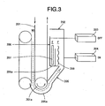
- Fig. 3 is an enlarged side view showing an outline of the exclusive storage box 202 of the paper-money receipt/payment machine 1
- Fig. 4 is an enlarged front view showing an outline of the exclusive storage box 202.
- a lower conveyance belt 201 of the lower paper-money mechanism 1b simply represents a part of the paper-money conveyance paths 901a to 901d shown in Fig. 1 .
- the lower conveyance belt 201 is driven by a lower paper-money conveyance mechanism motor 200.
- Two lengths of the lower conveyance belt 201 are provided in parallel in a conveyance width direction and stretched between two inner ones among four conveyance rollers 201a provided at a lower end thereof as shown in Fig. 4 .
- the lower paper-money conveyance mechanism motor 200 drives the lower conveyance belt 201 whereby discharge/storage of paper money into the money reception box 60 and the recycle boxes 80a to 80c is carried out.
- the exclusive storage box 202 is mainly composed of a conveyance guide 205, a conveyance guide 206, and two solenoids 203, 204 for movement of the conveyance guides 205, 206.
- the three guide pawls 205a are arranged laterally so as to be positioned between the respective four conveyance rollers 201a arranged laterally at intervals.
- the guide pawls 205a of the conveyance guide 205 function as guidance means to lead an accumulated article/jammed paper money 209 into the exclusive storage box 202 and also function as guidance means when discharging/storing a conveyance path check sheet 207 onto a paper-money conveyance path (conveyance path by the lower conveyance belt 201) at the time of normal operation.
- the conveyance guide 206 is a guide, which carries out discharge/storage of the conveyance path check sheet 207.
- a movable lid 206a (see Fig. 3 ) capable of opening and closing in a vertical direction is provided on a bottom portion of a storage space E of the conveyance guide 206.
- the movable lid 206a is maintained in a horizontal state by bias means such as spring, etc. and will not be caused by a weight of the conveyance path check sheet 207 to open downward in a state, in which the conveyance path check sheet 207 is placed thereon.
- the movable lid 206a is pushed open upward by the conveyance path check sheet 207, which is moved upward by receiving a conveying force of the lower conveyance belt 201.
- Fig. 5 is a block diagram showing the construction of the paper-money receipt/payment machine 1.
- the paper-money receipt/payment machine 1 comprises the money receipt/payment opening 20, through which a user charges/takes out paper money, the paper-money discrimination unit 30 for discrimination of paper money, the temporary holding unit 40, in which paper money as received is once stored until transactions are closed, a conveyance path 51, plural kinds of the reception boxes (60, 80), which are detachable and store paper money therein, the exclusive storage box 202, and a control unit 35, which controls these mechanisms.
- the reception boxes (60, 80) comprise the money reception box 60, in which paper money being not used for recycle is stored, and the recycle boxes 80a to 80c, which also serves as receipt/payment of money.
- the conveyance path 51 comprises the upper conveyance path 50, the lower conveyance path 90, and the connected conveyance path 501h for connection thereof.
- the control unit 35 is connected to a main control unit 106 of a cash automated-teller machine 108 through a bus 106a to control the paper-money receipt/payment machine 1 according to a command from the main control unit 106 and detection of a state of the paper-money receipt/payment machine 1. Also, a state of the paper-money receipt/payment machine 1 is transmitted to the main control unit 106 at need.
- control unit 35 is connected to drive motors of the respective units, that is, the money receipt/payment opening 20, the paper-money discrimination unit 30, the temporary holding unit 40, the conveyance path 51, the money reception box 60, the recycle boxes 80a to 80c, and the exclusive storage box 202, electromagnetic solenoids, and sensors in the paper-money receipt/payment machine 1 to drive and control the respective actuators (solenoids, motors, etc.) according to transactions while monitoring a state with the use of sensors.
- the respective actuators that is, the money receipt/payment opening 20, the paper-money discrimination unit 30, the temporary holding unit 40, the conveyance path 51, the money reception box 60, the recycle boxes 80a to 80c, and the exclusive storage box 202, electromagnetic solenoids, and sensors in the paper-money receipt/payment machine 1 to drive and control the respective actuators (solenoids, motors, etc.) according to transactions while monitoring a state with the use of sensors.
- the main control unit 106 is connected to an automatic machine monitoring system 107 through a circuit.
- the automatic machine monitoring system 107 monitors a state of the cash automated-teller machine 108 according to a signal received from the main control unit 106 to dispatch a maintenance personnel in case of abnormality to carry out maintenance of the cash automated-teller machine 108.
- Various operations of the paper-money receipt/payment machine 1 include a received money counting operation, a received money storing operation, and a money payment operation.
- control unit 35 moves a belt, which is connected to the upper conveyance path 50, a predetermined distance (or a predetermined period of time) in a reverse direction opposed to a forward direction being a direction of conveyance at the time of counting to convey an accumulated article or jammed paper money in the reverse direction, and then moves the belt again in the forward direction to convey the accumulated article or jammed paper money to the money receipt/payment opening 20.
- the control unit 35 functions as conveyance direction switching means at jam occasion.
- the accumulated article or jammed paper money cannot be conveyed in the reverse direction at the time of conveyance in the reverse direction (that is, in the case where conveyance of the accumulated article or jammed paper money in the reverse direction cannot be detected by a sensor or the like)
- the accumulated article or jammed paper money is conveyed in the forward direction to be transported to the money receipt/payment opening 20.
- the control unit 35 uses the conveyance path check sheet 207 (see Fig. 3 ) to carry out a foreign matter removal checking processing, in which it is confirmed that any foreign matter such as an accumulated article, jammed paper money, etc. is absent on the upper conveyance path 50 of the paper-money receipt/payment machine 1.
- the foreign matter removal checking processing determines and checks whether the conveyance path check sheet 207 can be conveyed in a normal manner.
- the control unit 35 which carries out the foreign matter removal checking processing, functions as conveyance-path confirming means.
- the control unit 35 transmits a control signal to the exclusive storage box 202 to make both the solenoids 203, 204 ON as shown in the enlarged side view of Fig. 6 .
- the conveyance guide 205 is put in a state, in which the guide pawls 205a shift to positions along the outer periphery of the conveyance roller 201a to be capable of discharge and storage.
- the conveyance guide 206 moves to a position, in which it overlaps the lower conveyance belt 201 of the lower paper-money mechanism 1b as viewed in side view, to be put in a state, in which the conveyance path check sheet 207 stored in the storage space E as a conveyance-path confirming medium storage box is pushed against and brought into contact with the lower conveyance belt 201.
- the conveyance path check sheet 207 is caused by a conveying force of the lower conveyance belt 201 to move downward to push open the movable lid 206a of the conveyance guide 206 to be discharged from the storage space E to be discharged onto the lower conveyance path 90 along the guide pawls 205a.
- the conveyance path check sheet 207 thus discharged is conveyed over the conveyance path 51 in a direction of discharge as indicated by an arrow Y1 by the lower paper-money conveyance mechanism motor 200 and the lower conveyance belt 201 to check the conveyance path 51 as a whole.
- the conveyance path check sheet 207 makes a round up to a distal end of the conveyance path 51 of the paper-money receipt/payment machine 1 to confirm that any accumulated article or jammed paper money is absent on the conveyance path 51, and then is reversely conveyed by the lower paper-money conveyance mechanism motor 200 and the lower conveyance belt 201 in flow of an arrow Y2 being a reverse direction to a direction at the time of discharge to be stored in the exclusive storage box 202.
- both the solenoids 203, 204 are made ON by a control signal, which the control unit 35 transmits to the exclusive storage box 202, as shown in an enlarged side view of Fig. 9 .
- the conveyance path check sheet 207 is conveyed around the conveyance roller 201a along the guide pawls 205a of the conveyance guide 205 to push up the movable lid 206a of the conveyance guide 206 to be stored in the storage space E.
- control unit 35 opens a money receipt/payment shutter 20a of the money receipt/payment opening 20.
- the direction of conveyance is switched over to a reverse direction to cause the conveyance path check sheet 207 to return to the exclusive storage box 202.
- the accumulated article or jammed paper money is stored in the exclusive storage box 202.
- the foreign matter removal checking processing with the use of the conveyance path check sheet 207 is carried out predetermined time or times (repeated plural times when the predetermined time is plural) to remove an accumulated article or jammed paper money present on the conveyance path 51 at the time of received money counting.
- jammed paper money and paper money remaining on the conveyance path 51 can be wholly conveyed to the money receipt/payment opening 20 to be surely returned to a user. Further, in the case where a user wants to deposit the returned paper money, it is also possible that a user straightens possible bent paper money and again opens the shutter of the money receipt/payment opening 20 to deposit money. Thereby, it is possible to fully automate removal of an accumulated article or jammed paper money present on the money conveyance path at the time of received money counting and resumption of normal operation.
- paper money, which cannot be received can be surely returned to a user by having a receipt or the like informing a user of the matter that jammed paper money is recovered, and returning that paper money, which is recovered into the exclusive storage box 202, to a user another day.
- conveyance path check sheet 207 detects presence of remains, it is also possible to permit a user to deposit money again provided that remains such as paper money, etc. on the conveyance path 51 can be removed. Thereby, it is possible to fully automate resumption at the time of received money counting.
- an accumulated article or jammed paper money 209 is present about, for example, the conveyance-path paper-money passage sensor 210b of the lower paper-money mechanism 1b of the paper-money receipt/payment machine 1 at the time of money reception and the accumulated article or jammed paper money 209 cannot be conveyed in a direction of reception.
- the lower conveyance belt 201 connected to the lower conveyance path 90 of the lower paper-money mechanism 1b is moved a predetermined distance (or a predetermined period of time) in a forward direction opposed to the direction of reception to move the accumulated article or jammed paper money 209 in the forward direction
- the lower conveyance belt 201 thus connected is used to convey the accumulated article or jammed paper money 209 in the reverse direction to store the accumulated article or jammed paper money 209 in the exclusive storage box 202.
- the lower conveyance belt 201 is conveyed in the reverse direction to store the accumulated article or jammed paper money 209 in the exclusive storage box 202.
- the solenoid 204 for the exclusive storage box 202 is made “ON” by a control signal of the control unit 35 as shown in Fig. 3 .
- the conveyance guide 205 is put in a state, in which the guide pawls 205a shift to positions along the outer periphery of the conveyance roller 201a to be capable of storage.
- the solenoid 203 is made "OFF” and the conveyance guide 206 is put in a state separate from the lower conveyance belt 201.
- a conveying force of the lower conveyance belt 201 causes the accumulated article or jammed paper money 209 to move along the guide pawls 205a to be stored in a storage space F.
- the control unit 35 carries out a remains confirming processing to confirm whether an accumulated article or jammed paper money remains on the conveyance path 51 of the paper-money receipt/payment machine 1.
- the remains confirming processing is almost the same as a foreign matter removal checking processing subsequent to the foreign matter removal processing at the time of received money counting described above.
- a difference resides in that remains are returned to the money receipt/payment opening 20 at the time of received money counting but remains are not returned to the money receipt/payment opening 20 at the time of money reception and only presence of remains is confirmed.
- control unit 35 carries out the foreign matter removal checking processing described above to perform confirmation of remains and storage into the exclusive storage box 202 in the case where remains are present.
- paper money, which cannot be received and stored can be surely returned to a user by having a receipt or the like informing the user of the matter that jammed paper money is recovered, and returning paper money, which is recovered into the exclusive storage box 202, to the user another day.
- an accumulated article or jammed paper money 209 is present about, for example, the conveyance-path paper-money passage sensor 210b of the lower paper-money mechanism 1b of the paper-money receipt/payment machine 1 at the time of money payment.
- the lower conveyance belt 201 connected to the lower conveyance path 90 is moved a predetermined distance (or a predetermined period of time) in a direction of money payment to move the accumulated article or jammed paper money 209
- the lower conveyance belt 201 is conveyed in the reverse direction to store the accumulated article or jammed paper money 209 in the exclusive storage box 202.
- the reason for movement over a predetermined distance in the direction of money payment is that in a midway state, in which paper money is partially discharged from paper money discharge ports of the money reception box 60 and the recycle boxes 80a to 80c, the paper money should be completely discharged onto the lower conveyance path 90.
- the control unit 35 carries out the foreign matter removal checking processing described above. After it is confirmed in the foreign matter removal checking processing that any accumulated article or jammed paper money is absent on the conveyance path 51 of the paper-money receipt/payment machine 1, all paper money conveyed to the money receipt/payment opening 20 and paper money present on the conveyance path 51 are recovered into the money reception box 60 and the recycle boxes 80a to 80c, which correspond to respective paper money, and money is paid to a user again.
- the direction of conveyance is switched over to cause the conveyance path check sheet 207 to return to the exclusive storage box 202 and at the same time the accumulated article or jammed paper money are also stored in the exclusive storage box 202.
- Checking of the conveyance path with the conveyance path check sheet 207 is performed predetermined times. In this manner, resumption to the normal operation can be fully automated by removing an accumulated article or jammed paper money present on the paper money conveyance path.
- the main control unit 106 informs the automatic machine monitoring system 107 of the matter that jammed paper money and the conveyance path check sheet 207 are recovered into the exclusive storage box 202. Thereby, it is possible to dispatch a maintenance personnel to the apparatus, while the paper-money receipt/payment machine 1 operates upon automatic resumption, to recover jammed paper money in the exclusive storage box 202 and the conveyance path check sheet 207.
- the paper-money receipt/payment machine 1 described above makes it possible to provide a paper-money handling apparatus capable of storage of a medium, such as an accumulated article of jammed paper money on the conveyance path 51, which has an adverse influence on operation, and confirmation of presence or absence of remains to enable resumption to be fully automated.
- the storage space E for storage of the conveyance path check sheet 207 and the storage space F for storage of the accumulated article or jammed paper money 209 are provided in the exclusive storage box 202 disposed in one location, assembly into the paper-money receipt/payment machine 1 is made possible at low cost and in a small space.
- the guide pawls 205a are commonly used for guidance of the conveyance path check sheet 207 to the storage space E from the lower conveyance path 90 and guidance of the accumulated article or jammed paper money 209 to the storage space F from the lower conveyance path 90, it is possible to decrease drive units to lead to manufacture at low cost and in a small space and to simplify control of the control unit 35. Also, it is possible to prevent an accumulated article and paper money in operation from being mixed.
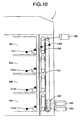
- both the solenoids 203, 204 in the exclusive storage box 202 are made "OFF" in a normal state, in which a foreign matter such as accumulated article, jammed paper money, etc. is not detected. Therefore, as shown in an enlarged side view of Fig. 11 , the guide pawls 205a of the conveyance guide 205 retreat from the lower conveyance path 90, so that paper money conveyed on the lower conveyance path 90 cannot be taken into the exclusive storage box 202. Also, since the conveyance guide 206 is not in contact with the lower conveyance belt 201, the conveyance path check sheet 207 is not discharged. Accordingly, the exclusive storage box 202 does not have any influence on normal operation of the paper-money receipt/payment machine 1.
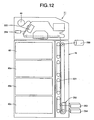
- a paper-money receipt/payment machine 11 in which an exclusive storage box 202 is provided at both ends (both ends of a conveyance path capable of conveyance in dual directions) of a conveyance path 51, will be described as a second embodiment with reference to a side view of the paper-money receipt/payment machine 11 shown in Fig. 12 .
- an exclusive storage box 222 is provided in a position near a temporary holding unit 40 on an upper conveyance path 50 in addition to the exclusive storage box 202 according to the first embodiment.
- the exclusive storage box 222 functions only to store an accumulated article or jammed paper money and is switched over by a solenoid 224 between a state communicated to the upper conveyance path 50 and a state separated therefrom.
- the exclusive storage box 222 and the exclusive storage box 202 provide a construction, in which storage boxes are present at both ends of the conveyance path 51. Since the remaining construction is the same as that of the first embodiment, the same reference numerals denote the same constituent elements as those in the latter and a detailed description therefor is omitted.
- the paper-money receipt/payment machine 11 At the time of received money counting, the paper-money receipt/payment machine 11 according to the second embodiment carries out the same operation as that in the first embodiment.
- the control unit 35 makes a solenoid 224 at a conveyance switchover gate "ON" in the case where an accumulated article or jammed paper money is generated on the conveyance path 51.
- the upper conveyance path 50 and the exclusive storage box 222 are connected to each other to convey the accumulated article or jammed paper money in a forward direction to store the same in the exclusive storage box 222.
- the accumulated article or jammed paper money is removed from the upper conveyance path 50.
- the conveyance path 51 is operated in the reverse direction at the time of storage to store paper money, so that paper money can be caught by a guide or the like on the conveyance path 51 to be folded in some cases.
- jammed paper money being thus folded is conveyed in the same reverse direction, a portion as folded is again caught by the guide and so cannot be conveyed.
- the foreign matter removal checking processing described in the first embodiment is carried out, and after the conveyance path check sheet 207 is discharged from the exclusive storage box 202 to make a round on the conveyance path 51, it is stored in the exclusive storage box 202.
- the same operation as that in the first embodiment is carried out at the time of money payment.
- the reason why conveyance is made in the reverse direction when an accumulated article or jammed paper money is present at the time of money payment is that in many cases, jammed paper money can be conveyed in the reverse direction but not in the forward direction according to a state of jam.
- the conveyance path 51 is operated in the forward direction at the time of money payment to convey paper money to the money receipt/payment opening 20, and at that time, paper money can be caught by a guide or the like on the conveyance path 51 to be folded.
- jammed paper money being thus folded is conveyed in the same forward direction, a portion as folded is again caught by the guide and so cannot be conveyed.
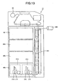
- a paper-money receipt/payment machine 12 in which instead of the exclusive storage box 202, a recycle box 80e including two parts, that is, a recycle portion 213 and a storage space 214 is provided at a distal end of a conveyance path 51, will be described as a third embodiment with reference to a side view of the paper-money receipt/payment machine 12 shown in Fig. 13 .
- the recycle portion 213 and the storage space 214 are provided as two recycle spaces in the recycle box 80e, and the both spaces can perform discharge/storage of paper money and, respectively, can be made use of as a recycle box.
- the remaining recycle boxes 80a to 80c comprise one recycle space and the recycle box 80e is different in this respect from the remaining recycle boxes 80a to 80c.
- the recycle box 80e is small in paper money storage volume but is adequately useful in case of being used for recycle of large denomination paper money and denomination paper money of small frequency in use.
- the storage space 214 of the recycle box 80e is used to store jammed paper money and the recycle portion 213 is set to perform discharge/storage of the conveyance path check sheet 207.
- Use of the storage space 214 enables the same operation as that of the conveyance guide 205 in the exclusive storage box 202 described in the first embodiment, which stores an accumulated article or jammed paper money. Also, use of the recycle portion 213 enables the same operation as that of the conveyance guide 206 in the exclusive storage box 202 described in the first embodiment, which performs discharge/storage of the conveyance path check sheet 207.
- Respective operations of the paper-money receipt/payment machine 12 at the time of received money counting, at the time of money reception, and at the time of money payment are the same as those in the first embodiment except that an accumulated article or jammed paper money is stored in the storage space 214 and the conveyance path check sheet 207 is stored in the recycle portion 213.
- the accumulated article or jammed paper money is conveyed into the recycle box 80e via the lower conveyance belt 201.
- the accumulated article or jammed paper money is taken into the storage space 214 through a guide, depiction of which is omitted, and put in order by a push plate 215 to be stored.
- the conveyance path check sheet 207 When the conveyance path check sheet 207 is discharged from the recycle portion 213, the conveyance path check sheet 207 is caused by a push plate 216 to abut against a conveyance guide, depiction of which is omitted, and discharged onto the conveyance path 51.
- the conveyance path check sheet 207 When the conveyance path check sheet 207 is stored, the conveyance path check sheet 207 is conveyed into the recycle box 80e through the lower conveyance belt 201 and taken into the recycle portion 213 through a guide, depiction of which is omitted, to be stored by the push plate 216.
- the invention is not limited to only the constructions of the embodiments described above but it is possible to obtain many embodiments.
Landscapes
- Physics & Mathematics (AREA)
- General Physics & Mathematics (AREA)
- Controlling Sheets Or Webs (AREA)
- Separation, Sorting, Adjustment, Or Bending Of Sheets To Be Conveyed (AREA)
- Delivering By Means Of Belts And Rollers (AREA)
- Pile Receivers (AREA)
Claims (5)
- Dispositif de manipulation de feuilles de papier ayant un chemin de transport capable de transporter une feuille de papier dans les deux sens, et une unité de discrimination agencée en position médiane sur le chemin de transport afin de discriminer la feuille de papier, le dispositif comportant :une boîte de stockage de feuille de papier rejetée pour un stockage d'une feuille de papier devant être rejetée, etune boîte de stockage de feuille de papier de bourrage, agencée séparément par rapport à la boîte de stockage de feuille de papier rejetée, pour un stockage d'une feuille de papier de bourrage, etdans lequel la boîte de stockage de feuille de papier de bourrage est agencée à une extrémité ou aux deux extrémités du chemin de transport.
- Dispositif de manipulation de feuilles de papier selon la revendication 1, comportant en outre :des moyens de détection de bourrage détectant un bourrage de la feuille de papier sur le chemin de transport,des moyens de commutation de sens de transport à l'occasion d'un bourrage qui commutent un sens de transport sur le chemin de transport entre une direction antérieure au bourrage et une direction inverse dans le cas où un bourrage est détecté par les moyens de détection de bourrage, etdes moyens de guidage qui guident la feuille de papier de bourrage étant transportée vers la boîte de stockage de feuille de papier de bourrage.
- Dispositif de manipulation de feuilles de papier selon la revendication 2, comportant en outre les éléments suivantes :une boîte de stockage de support de confirmation de chemin de transport qui stocke un support de confirmation de chemin de transport pour confirmer le chemin de transport, etdes moyens de confirmation de chemin de transport qui transportent le support de confirmation de chemin de transport sur le chemin de transport après que la feuille de papier de bourrage ait été guidée vers la boîte de stockage de feuille de papier de bourrage.
- Dispositif de manipulation de feuilles de papier selon la revendication 3, dans lequel la boîte de stockage de feuille de papier de bourrage et la boîte de stockage de support de confirmation de chemin de transport sont agencées à proximité l'une de l'autre, et
les moyens de guidage sont structurés pour être communément utilisés pour un guidage de la feuille de papier de bourrage à partir du chemin de transport vers la boîte de stockage de feuille de papier de bourrage, et un guidage du support de confirmation du chemin de transport à partir du chemin de transport vers la boîte de stockage de support de confirmation de chemin de transport. - Dispositif de manipulation de feuilles de papier, comportant :un chemin de transport capable de transporter une feuille de papier dans les deux sens, une unité de discrimination agencée en position médiane sur le chemin de transport pour discriminer la feuille de papier, et deux unités de stockage ou plus pour l'élimination/le stockage d'une feuille de papier, etdans lequel les unités de stockage sont structurées de telle manière que les unités de stockage peuvent être commutées en fonctionnement pour pouvoirêtre manipulées en tant que boîtes de stockage de feuille de papier pour réception/paiement, dans lesquelles une feuille de papier pour réception/paiement est conservée,être manipulées en tant que boîtes de stockage de feuille de papier de bourrage pour le stockage d'une feuille de papier de bourrage, etêtre manipulées en tant que boîtes de stockage de support de confirmation de chemin de transport, dans lesquelles un support de confirmation de chemin de transport pour la confirmation du chemin de transport est conservé.
Applications Claiming Priority (1)
| Application Number | Priority Date | Filing Date | Title |
|---|---|---|---|
| JP2006217961A JP5042559B2 (ja) | 2006-08-10 | 2006-08-10 | 紙葉類取扱装置 |
Publications (2)
| Publication Number | Publication Date |
|---|---|
| EP1892680A1 EP1892680A1 (fr) | 2008-02-27 |
| EP1892680B1 true EP1892680B1 (fr) | 2009-04-08 |
Family
ID=38660349
Family Applications (1)
| Application Number | Title | Priority Date | Filing Date |
|---|---|---|---|
| EP07014094A Not-in-force EP1892680B1 (fr) | 2006-08-10 | 2007-07-18 | Appareil de manipulation de feuilles de papier |
Country Status (6)
| Country | Link |
|---|---|
| US (1) | US7673874B2 (fr) |
| EP (1) | EP1892680B1 (fr) |
| JP (1) | JP5042559B2 (fr) |
| KR (1) | KR100895560B1 (fr) |
| CN (1) | CN101123014B (fr) |
| DE (1) | DE602007000846D1 (fr) |
Families Citing this family (38)
| Publication number | Priority date | Publication date | Assignee | Title |
|---|---|---|---|---|
| US8812394B1 (en) * | 2008-11-10 | 2014-08-19 | Bank Of America Corporation | Process and data integration of additional funds into cash handling device and reconciliation |
| JP5212090B2 (ja) * | 2008-12-25 | 2013-06-19 | 沖電気工業株式会社 | 自動取引装置 |
| JP5465188B2 (ja) * | 2009-02-02 | 2014-04-09 | 日本金銭機械株式会社 | 紙葉類取扱装置 |
| JP5275875B2 (ja) * | 2009-03-27 | 2013-08-28 | 富士通フロンテック株式会社 | 紙葉類処理装置 |
| JP4941526B2 (ja) * | 2009-09-07 | 2012-05-30 | 沖電気工業株式会社 | 紙幣処理装置及びそれに使用するパトロール券 |
| JP5474492B2 (ja) * | 2009-11-05 | 2014-04-16 | グローリー株式会社 | 紙幣入金装置 |
| JP5410932B2 (ja) * | 2009-11-25 | 2014-02-05 | 日立オムロンターミナルソリューションズ株式会社 | 紙幣取扱装置 |
| JP5427617B2 (ja) | 2010-01-13 | 2014-02-26 | 日立オムロンターミナルソリューションズ株式会社 | 紙幣収納庫および紙幣取扱装置 |
| TWI425448B (zh) * | 2010-02-02 | 2014-02-01 | Nippon Kinsen Kikai Kk | 紙張類處理裝置 |
| RU2564506C1 (ru) * | 2010-11-19 | 2015-10-10 | Хитачи-Омрон Терминал Солюшнз, Корп. | Устройство внесения и извлечения банкнот |
| JP5622199B2 (ja) * | 2011-02-01 | 2014-11-12 | 日立オムロンターミナルソリューションズ株式会社 | 紙幣取扱装置 |
| WO2012114449A1 (fr) * | 2011-02-22 | 2012-08-30 | グローリー株式会社 | Système de manipulation d'argent liquide, calculateur d'argent liquide, dispositif d'entrée et de sortie d'argent liquide et procédé de manipulation d'argent liquide |
| JP2012176827A (ja) * | 2011-02-25 | 2012-09-13 | Ricoh Co Ltd | ジャム処理アシスト装置及び前記ジャム処理アシスト装置を備えた画像形成装置 |
| JP5742451B2 (ja) * | 2011-05-11 | 2015-07-01 | 沖電気工業株式会社 | 紙幣入出金装置 |
| JP5706802B2 (ja) * | 2011-11-17 | 2015-04-22 | 日立オムロンターミナルソリューションズ株式会社 | 紙葉類処理装置及び紙葉類処理方法 |
| JP5790450B2 (ja) * | 2011-11-30 | 2015-10-07 | 沖電気工業株式会社 | 紙幣処理装置 |
| US9027918B2 (en) * | 2012-05-28 | 2015-05-12 | Oki Electric Industry Co., Ltd. | Medium processor having medium storing boxes flexibly loadable in a slot of a medium storage |
| JP5891957B2 (ja) * | 2012-06-01 | 2016-03-23 | 沖電気工業株式会社 | 媒体繰出収納装置及び媒体処理装置 |
| US9589410B2 (en) * | 2013-06-03 | 2017-03-07 | Hitachi-Omron Terminal Solutions, Corp. | Paper money handling apparatus |
| CN103560911A (zh) * | 2013-10-30 | 2014-02-05 | 深圳市怡化电脑有限公司 | 一种金融自助设备主动预防维修维护的方法及系统 |
| CN104008604B (zh) * | 2014-05-04 | 2017-01-11 | 昆山古鳌电子机械有限公司 | 一种纸张类处理装置 |
| CN104167056A (zh) * | 2014-08-04 | 2014-11-26 | 浙江方泰电器有限公司 | 一种多口清分机用的双联收钞模块 |
| CN105788065B (zh) * | 2015-01-09 | 2018-07-27 | 日立欧姆龙金融系统有限公司 | 现金处理装置 |
| CN105989664A (zh) * | 2015-02-12 | 2016-10-05 | 日立金融设备系统(深圳)有限公司 | 自助设备及其计数方法 |
| CN104637156B (zh) * | 2015-03-06 | 2017-05-24 | 广州广电运通金融电子股份有限公司 | 纸币转出控制方法、装置以及纸币存储设备 |
| JP6388721B2 (ja) * | 2015-07-22 | 2018-09-12 | 富士通フロンテック株式会社 | 紙葉類取扱装置及び紙葉類取扱装置の制御方法 |
| CN108806056B (zh) * | 2016-04-05 | 2022-09-09 | 南通大学 | 结构合理的公交车用投币机 |
| JP6669884B2 (ja) * | 2016-09-28 | 2020-03-18 | 富士通フロンテック株式会社 | 紙葉類取扱装置及び紙葉類取扱方法 |
| JP6809382B2 (ja) * | 2017-05-30 | 2021-01-06 | 沖電気工業株式会社 | 媒体取込装置及び媒体処理装置 |
| JP2019109644A (ja) * | 2017-12-18 | 2019-07-04 | 富士通フロンテック株式会社 | 自動機監視装置 |
| CN108629428B (zh) * | 2018-05-03 | 2021-07-02 | 江苏建筑职业技术学院 | 基于互联网共享的自助复印打印系统的智能废纸回收方法 |
| CN108946116B (zh) * | 2018-09-29 | 2024-02-09 | 湖南中天云科电子有限公司 | 一种电子文凭签发机 |
| CN109461249B (zh) * | 2018-11-23 | 2024-08-06 | 恒银金融科技股份有限公司 | 一种纸币堆叠整理装置 |
| CN111192402B (zh) * | 2019-10-09 | 2021-12-21 | 东方通信股份有限公司 | 一种纸币存取款处理装置 |
| CN111275882B (zh) * | 2020-01-22 | 2023-03-31 | 山东新北洋信息技术股份有限公司 | 现金处理设备及其控制方法 |
| CN113256911A (zh) * | 2020-12-31 | 2021-08-13 | 深圳怡化电脑股份有限公司 | 一种卡钞处理方法、系统、存取款设备和存储介质 |
| JP7729176B2 (ja) * | 2021-10-27 | 2025-08-26 | 株式会社リコー | 搬送装置、印刷装置、液体を吐出する装置 |
| CN115240318A (zh) * | 2022-07-21 | 2022-10-25 | 中国银行股份有限公司 | 残币兑换方法、装置、计算机可读存储介质及自动取款机 |
Family Cites Families (20)
| Publication number | Priority date | Publication date | Assignee | Title |
|---|---|---|---|---|
| JPS5627490A (en) * | 1979-08-09 | 1981-03-17 | Tokyo Shibaura Electric Co | Paper document classifier |
| US4513439A (en) * | 1982-07-12 | 1985-04-23 | Ardac, Inc. | Security validator |
| JPS61287641A (ja) * | 1985-06-11 | 1986-12-18 | Toshiba Corp | 自動出金装置 |
| JPS62135988A (ja) * | 1985-12-10 | 1987-06-18 | 沖電気工業株式会社 | 自動入出金機 |
| US4928230A (en) * | 1987-03-23 | 1990-05-22 | Kabushiki Kaisha Toshiba | Automatic transacting apparatus |
| JPS6476181A (en) * | 1987-09-17 | 1989-03-22 | Ibm | Automatic handling of paper money and paper money storage used therefor |
| JPH081670B2 (ja) * | 1989-10-13 | 1996-01-10 | 株式会社日立製作所 | 現金自動取引装置の紙幣搬送制御方法 |
| JP3212673B2 (ja) * | 1992-03-12 | 2001-09-25 | グローリー工業株式会社 | 紙幣ジャムの復旧方法及び復旧装置 |
| JPH06219596A (ja) | 1993-01-21 | 1994-08-09 | Oki Electric Ind Co Ltd | 紙幣自動支払装置 |
| JP2584407Y2 (ja) * | 1993-03-19 | 1998-11-05 | 株式会社田村電機製作所 | カード搬送装置 |
| JP3248972B2 (ja) * | 1993-04-07 | 2002-01-21 | 沖電気工業株式会社 | 紙幣入出金装置 |
| JP2654611B2 (ja) * | 1994-12-26 | 1997-09-17 | 日本電気株式会社 | 現金自動取引機 |
| KR100284843B1 (ko) * | 1996-09-20 | 2001-03-15 | 가나이 쓰도무 | 현금자동거래장치 |
| JP3296753B2 (ja) * | 1997-06-18 | 2002-07-02 | 沖電気工業株式会社 | 自動取引装置管理システムの自動復旧方法 |
| JP3849913B2 (ja) * | 2000-10-05 | 2006-11-22 | 日立オムロンターミナルソリューションズ株式会社 | 紙葉類取扱装置 |
| GB2369230B (en) * | 2000-11-01 | 2005-01-19 | Lg Electronics Inc | A clutch system and a control method of media dispenser |
| JP4053539B2 (ja) * | 2002-08-30 | 2008-02-27 | 富士通株式会社 | 紙葉類処理装置、紙葉類処理装置における紙葉類角折れ検出方法および、紙葉類処理装置における紙葉類角折れ検出プログラム |
| JP2004224481A (ja) * | 2003-01-21 | 2004-08-12 | Toshiba Corp | 紙葉類処理装置 |
| JP4418207B2 (ja) * | 2003-10-28 | 2010-02-17 | 日立オムロンターミナルソリューションズ株式会社 | 紙幣取扱装置 |
| JP4408373B2 (ja) * | 2004-01-23 | 2010-02-03 | 日立オムロンターミナルソリューションズ株式会社 | 紙幣入出金装置 |
-
2006
- 2006-08-10 JP JP2006217961A patent/JP5042559B2/ja not_active Expired - Fee Related
-
2007
- 2007-06-22 CN CN2007101125911A patent/CN101123014B/zh not_active Expired - Fee Related
- 2007-07-18 EP EP07014094A patent/EP1892680B1/fr not_active Not-in-force
- 2007-07-18 DE DE602007000846T patent/DE602007000846D1/de active Active
- 2007-07-19 KR KR1020070072119A patent/KR100895560B1/ko not_active Expired - Fee Related
- 2007-07-19 US US11/779,902 patent/US7673874B2/en not_active Expired - Fee Related
Also Published As
| Publication number | Publication date |
|---|---|
| US7673874B2 (en) | 2010-03-09 |
| DE602007000846D1 (de) | 2009-05-20 |
| KR100895560B1 (ko) | 2009-04-29 |
| JP2008041030A (ja) | 2008-02-21 |
| EP1892680A1 (fr) | 2008-02-27 |
| CN101123014A (zh) | 2008-02-13 |
| JP5042559B2 (ja) | 2012-10-03 |
| KR20080014607A (ko) | 2008-02-14 |
| CN101123014B (zh) | 2010-09-15 |
| US20080038038A1 (en) | 2008-02-14 |
Similar Documents
| Publication | Publication Date | Title |
|---|---|---|
| US7673874B2 (en) | Paper sheet handling apparatus | |
| US6889898B2 (en) | Bill deposit/withdrawal machine for depositing/withdrawing bills | |
| EP3264377B1 (fr) | Dispositif d'automatisation bancaire pour employé de banque et son procédé de commande | |
| JP3248972B2 (ja) | 紙幣入出金装置 | |
| CN102365660A (zh) | 纸张类处理装置 | |
| WO2014155644A1 (fr) | Dispositif de manipulation de feuille de papier et dispositif de transaction automatique | |
| JPH0585948B2 (fr) | ||
| JP2979519B2 (ja) | 紙幣入出金装置 | |
| KR101628478B1 (ko) | 수표 및 지폐 입출금장치와 수표 및 지폐 입출금방법 | |
| WO2018066428A1 (fr) | Mécanisme de tri de pièces de monnaie et dispositif de traitement de pièces de monnaie | |
| JP2010231262A (ja) | 紙葉取扱装置 | |
| JP6584630B2 (ja) | 紙葉類取扱装置 | |
| JP6660263B2 (ja) | 硬貨収納繰出機構および硬貨処理装置 | |
| JP3626289B2 (ja) | 貨幣処理装置 | |
| JPH06219596A (ja) | 紙幣自動支払装置 | |
| JP4768293B2 (ja) | 紙葉類収納装置 | |
| JP2716623B2 (ja) | 紙幣入出金装置 | |
| JP2018180762A (ja) | 貨幣処理機および貨幣処理方法 | |
| JP3985088B2 (ja) | 紙幣識別装置 | |
| JP4866405B2 (ja) | 紙幣入出金機 | |
| JPH07272037A (ja) | 紙幣処理装置 | |
| JPH11224360A (ja) | 紙幣取扱装置 | |
| KR20080002045A (ko) | 반송로개방이 감지되는 금융자동화기기 및 그 운용방법 | |
| JPH1049724A (ja) | 自動取引装置および自動取引装置に用いられる検査券 | |
| JPH04291486A (ja) | 紙幣自動取扱装置 |
Legal Events
| Date | Code | Title | Description |
|---|---|---|---|
| PUAI | Public reference made under article 153(3) epc to a published international application that has entered the european phase |
Free format text: ORIGINAL CODE: 0009012 |
|
| AK | Designated contracting states |
Kind code of ref document: A1 Designated state(s): AT BE BG CH CY CZ DE DK EE ES FI FR GB GR HU IE IS IT LI LT LU LV MC MT NL PL PT RO SE SI SK TR |
|
| AX | Request for extension of the european patent |
Extension state: AL BA HR MK YU |
|
| 17P | Request for examination filed |
Effective date: 20080331 |
|
| GRAP | Despatch of communication of intention to grant a patent |
Free format text: ORIGINAL CODE: EPIDOSNIGR1 |
|
| AKX | Designation fees paid |
Designated state(s): DE FR GB |
|
| GRAS | Grant fee paid |
Free format text: ORIGINAL CODE: EPIDOSNIGR3 |
|
| GRAA | (expected) grant |
Free format text: ORIGINAL CODE: 0009210 |
|
| AK | Designated contracting states |
Kind code of ref document: B1 Designated state(s): DE FR GB |
|
| REG | Reference to a national code |
Ref country code: GB Ref legal event code: FG4D |
|
| REF | Corresponds to: |
Ref document number: 602007000846 Country of ref document: DE Date of ref document: 20090520 Kind code of ref document: P |
|
| PLBE | No opposition filed within time limit |
Free format text: ORIGINAL CODE: 0009261 |
|
| STAA | Information on the status of an ep patent application or granted ep patent |
Free format text: STATUS: NO OPPOSITION FILED WITHIN TIME LIMIT |
|
| 26N | No opposition filed |
Effective date: 20100111 |
|
| REG | Reference to a national code |
Ref country code: FR Ref legal event code: PLFP Year of fee payment: 10 |
|
| PGFP | Annual fee paid to national office [announced via postgrant information from national office to epo] |
Ref country code: FR Payment date: 20160613 Year of fee payment: 10 |
|
| PGFP | Annual fee paid to national office [announced via postgrant information from national office to epo] |
Ref country code: DE Payment date: 20160712 Year of fee payment: 10 Ref country code: GB Payment date: 20160713 Year of fee payment: 10 |
|
| REG | Reference to a national code |
Ref country code: DE Ref legal event code: R119 Ref document number: 602007000846 Country of ref document: DE |
|
| GBPC | Gb: european patent ceased through non-payment of renewal fee |
Effective date: 20170718 |
|
| REG | Reference to a national code |
Ref country code: FR Ref legal event code: ST Effective date: 20180330 |
|
| PG25 | Lapsed in a contracting state [announced via postgrant information from national office to epo] |
Ref country code: GB Free format text: LAPSE BECAUSE OF NON-PAYMENT OF DUE FEES Effective date: 20170718 Ref country code: DE Free format text: LAPSE BECAUSE OF NON-PAYMENT OF DUE FEES Effective date: 20180201 |
|
| PG25 | Lapsed in a contracting state [announced via postgrant information from national office to epo] |
Ref country code: FR Free format text: LAPSE BECAUSE OF NON-PAYMENT OF DUE FEES Effective date: 20170731 |