EP1892823A2 - Verfahren zur Regelung eines Netzstromrichters für Schienenfahrzeuge - Google Patents
Verfahren zur Regelung eines Netzstromrichters für Schienenfahrzeuge Download PDFInfo
- Publication number
- EP1892823A2 EP1892823A2 EP07111151A EP07111151A EP1892823A2 EP 1892823 A2 EP1892823 A2 EP 1892823A2 EP 07111151 A EP07111151 A EP 07111151A EP 07111151 A EP07111151 A EP 07111151A EP 1892823 A2 EP1892823 A2 EP 1892823A2
- Authority
- EP
- European Patent Office
- Prior art keywords
- mains
- current
- bias
- converter
- transformer
- Prior art date
- Legal status (The legal status is an assumption and is not a legal conclusion. Google has not performed a legal analysis and makes no representation as to the accuracy of the status listed.)
- Granted
Links
- 238000000034 method Methods 0.000 title claims abstract description 28
- 230000001105 regulatory effect Effects 0.000 title abstract description 4
- 238000011156 evaluation Methods 0.000 claims description 15
- 238000005259 measurement Methods 0.000 claims description 3
- 238000004458 analytical method Methods 0.000 claims description 2
- 230000005415 magnetization Effects 0.000 abstract 1
- 238000004804 winding Methods 0.000 description 6
- 230000033228 biological regulation Effects 0.000 description 5
- 230000001276 controlling effect Effects 0.000 description 3
- 238000012806 monitoring device Methods 0.000 description 3
- 238000012937 correction Methods 0.000 description 2
- 238000001514 detection method Methods 0.000 description 2
- 238000005516 engineering process Methods 0.000 description 2
- 238000001914 filtration Methods 0.000 description 2
- 230000003137 locomotive effect Effects 0.000 description 2
- 230000007257 malfunction Effects 0.000 description 2
- 230000009466 transformation Effects 0.000 description 2
- 230000008901 benefit Effects 0.000 description 1
- 230000001419 dependent effect Effects 0.000 description 1
- 238000010586 diagram Methods 0.000 description 1
- 230000006872 improvement Effects 0.000 description 1
- 238000004519 manufacturing process Methods 0.000 description 1
- 238000012544 monitoring process Methods 0.000 description 1
- 230000010355 oscillation Effects 0.000 description 1
- 230000004044 response Effects 0.000 description 1
- 239000004065 semiconductor Substances 0.000 description 1
- 230000003595 spectral effect Effects 0.000 description 1
- 230000001629 suppression Effects 0.000 description 1
Images

Classifications
-
- H—ELECTRICITY
- H02—GENERATION; CONVERSION OR DISTRIBUTION OF ELECTRIC POWER
- H02M—APPARATUS FOR CONVERSION BETWEEN AC AND AC, BETWEEN AC AND DC, OR BETWEEN DC AND DC, AND FOR USE WITH MAINS OR SIMILAR POWER SUPPLY SYSTEMS; CONVERSION OF DC OR AC INPUT POWER INTO SURGE OUTPUT POWER; CONTROL OR REGULATION THEREOF
- H02M7/00—Conversion of AC power input into DC power output; Conversion of DC power input into AC power output
- H02M7/02—Conversion of AC power input into DC power output without possibility of reversal
- H02M7/04—Conversion of AC power input into DC power output without possibility of reversal by static converters
- H02M7/12—Conversion of AC power input into DC power output without possibility of reversal by static converters using discharge tubes with control electrode or semiconductor devices with control electrode
- H02M7/21—Conversion of AC power input into DC power output without possibility of reversal by static converters using discharge tubes with control electrode or semiconductor devices with control electrode using devices of a triode or transistor type requiring continuous application of a control signal
- H02M7/217—Conversion of AC power input into DC power output without possibility of reversal by static converters using discharge tubes with control electrode or semiconductor devices with control electrode using devices of a triode or transistor type requiring continuous application of a control signal using semiconductor devices only
- H02M7/219—Conversion of AC power input into DC power output without possibility of reversal by static converters using discharge tubes with control electrode or semiconductor devices with control electrode using devices of a triode or transistor type requiring continuous application of a control signal using semiconductor devices only in a bridge configuration
-
- B—PERFORMING OPERATIONS; TRANSPORTING
- B60—VEHICLES IN GENERAL
- B60L—PROPULSION OF ELECTRICALLY-PROPELLED VEHICLES; SUPPLYING ELECTRIC POWER FOR AUXILIARY EQUIPMENT OF ELECTRICALLY-PROPELLED VEHICLES; ELECTRODYNAMIC BRAKE SYSTEMS FOR VEHICLES IN GENERAL; MAGNETIC SUSPENSION OR LEVITATION FOR VEHICLES; MONITORING OPERATING VARIABLES OF ELECTRICALLY-PROPELLED VEHICLES; ELECTRIC SAFETY DEVICES FOR ELECTRICALLY-PROPELLED VEHICLES
- B60L3/00—Electric devices on electrically-propelled vehicles for safety purposes; Monitoring operating variables, e.g. speed, deceleration or energy consumption
- B60L3/0023—Detecting, eliminating, remedying or compensating for drive train abnormalities, e.g. failures within the drive train
- B60L3/003—Detecting, eliminating, remedying or compensating for drive train abnormalities, e.g. failures within the drive train relating to inverters
-
- B—PERFORMING OPERATIONS; TRANSPORTING
- B60—VEHICLES IN GENERAL
- B60L—PROPULSION OF ELECTRICALLY-PROPELLED VEHICLES; SUPPLYING ELECTRIC POWER FOR AUXILIARY EQUIPMENT OF ELECTRICALLY-PROPELLED VEHICLES; ELECTRODYNAMIC BRAKE SYSTEMS FOR VEHICLES IN GENERAL; MAGNETIC SUSPENSION OR LEVITATION FOR VEHICLES; MONITORING OPERATING VARIABLES OF ELECTRICALLY-PROPELLED VEHICLES; ELECTRIC SAFETY DEVICES FOR ELECTRICALLY-PROPELLED VEHICLES
- B60L9/00—Electric propulsion with power supply external to the vehicle
-
- H—ELECTRICITY
- H02—GENERATION; CONVERSION OR DISTRIBUTION OF ELECTRIC POWER
- H02M—APPARATUS FOR CONVERSION BETWEEN AC AND AC, BETWEEN AC AND DC, OR BETWEEN DC AND DC, AND FOR USE WITH MAINS OR SIMILAR POWER SUPPLY SYSTEMS; CONVERSION OF DC OR AC INPUT POWER INTO SURGE OUTPUT POWER; CONTROL OR REGULATION THEREOF
- H02M1/00—Details of apparatus for conversion
- H02M1/40—Means for preventing magnetic saturation
-
- B—PERFORMING OPERATIONS; TRANSPORTING
- B60—VEHICLES IN GENERAL
- B60L—PROPULSION OF ELECTRICALLY-PROPELLED VEHICLES; SUPPLYING ELECTRIC POWER FOR AUXILIARY EQUIPMENT OF ELECTRICALLY-PROPELLED VEHICLES; ELECTRODYNAMIC BRAKE SYSTEMS FOR VEHICLES IN GENERAL; MAGNETIC SUSPENSION OR LEVITATION FOR VEHICLES; MONITORING OPERATING VARIABLES OF ELECTRICALLY-PROPELLED VEHICLES; ELECTRIC SAFETY DEVICES FOR ELECTRICALLY-PROPELLED VEHICLES
- B60L2200/00—Type of vehicles
- B60L2200/26—Rail vehicles
Definitions
- the invention relates to a method for controlling a mains converter for rail vehicles, wherein by means of a current collector, which picks up a mains voltage of a single-phase AC mains, the mains converter via a transformer, a mains power is supplied to the power converter and the output side, a constant DC link voltage is generated. Furthermore, the invention relates to an arrangement for carrying out the method.
- Mains power converters for mains-powered traction drives in rail vehicles have long been known from the prior art (see FIG. 1).
- the mains voltage of a feeding catenary for example, 15 kV, 16 2/3 Hz
- the track systems form the reference potential.
- a secondary winding of the transformer feeds via the regulated mains converter a voltage intermediate circuit with a held constant by the regulation of the mains rectifier DC link voltage.
- the power converter is preferably designed as a four-quadrant controller, as this allows a current largely arbitrary phase position to the contact wire voltage can be adjusted.
- a DC link voltage generator feeds a variable frequency, voltage three phase asynchronous motor to produce the desired drive torque in the motor at the present speed.
- harmonics occur in the mains current, in particular due to a premagnetization of the transformer with an associated strong increase of the magnetizing current. These harmonics are particularly undesirable when certain frequencies are affected, which are used by train operators in many countries for the train safety technology. For example, in Austria and Germany alternating voltage signals with a frequency of 100 Hz are used for track monitoring, whereby this frequency corresponds to the 6th harmonic in a 16 2/3 Hz network.
- a track is divided into track circuits, at the beginning of a 100 Hz alternating voltage between the two rails is applied.
- a frequency selective receive relay detects the voltage between the rails. If the supplied AC voltage is still present, the relay picks up and signals the track circuit as free. However, if there is a train on the track, the fed signal is short-circuited by the axles of the train and the receiving relay drops. The track circle is thus reported as occupied.
- the return current of a traction vehicle can influence the function of a track circuit if the mains current contains a 100 Hz harmonic.
- the traction motor's 100 Hz noise current must not exceed a limit value (e.g., 2A). Therefore, according to the state of the art in modern rail vehicles, a 100 Hz interference current monitoring device is provided, which separates the traction vehicle by means of a main switch from the grid in the event of an impermissible 100 Hz interference current crossing.
- Another method of avoiding 100 Hz harmonics is from the DE 44 34 378 C1 known.
- the 50 Hz current harmonic is suppressed by a disturbance current control implemented in the regulation of a four-quadrant controller. A primary-side bias of the transformer is not detected.
- a method of detecting a DC bias of the transformer of a vehicle operating on a single-phase AC mains with which a primary-side DC bias can be detected is based on the rectification of the measured primary current and a downstream bandpass filter, which is tuned to the mains frequency. If there is no DC bias, then the signal contains only even harmonics, but no spectral component at the line frequency. The output signal of the bandpass filter is therefore zero. If DC biasing is present, then the signal will include a power frequency component after rectification, which may be measured at the output of the bandpass filter, after half-wave unbalance. A measure to avoid a primary-side bias is not specified.
- Traction vehicles can be exposed to external conditions that lead to a primary-side bias of the transformer. It is known, for example, that in hoarfrost-covered overhead lines due to low temperatures, arcs occur between the overhead line and the current collector. The properties of these arcs are dependent on the polarity of the mains voltage, so that the tapped mains current has a significant DC component (see L. Buhrkall: "DC components due to ice on the overhead contact wire of AC electrified railways", Electric webs 103 (2005), No. 8, pages 380-389 ).
- the invention has for its object to provide an improvement over the prior art for a method of the type mentioned.
- this object is achieved by a method for controlling a mains converter for rail vehicles, by means of a current collector, which picks up a mains voltage of a single-phase AC mains, the mains converter via a transformer is supplied to a mains and the power converter on the output side, a constant DC link voltage is generated, on the transformer primary side, a DC component of the mains current is detected by means of suitable measuring and evaluation and wherein a direct current component corresponding direct current component is superimposed on a current setpoint secondary current control of the mains converter in such a way that counteracted by the current control secondary side DC counteracts a bias of the transformer.
- An advantageous embodiment of the invention provides that the primary-side DC component is detected by means of an active mains current transformer and a suitable evaluation device. With such a converter, a primary-side DC component is detected directly and fed directly to a controller for setting a DC nominal value.
- the primary-side DC component is detected by means of a passive mains current transformer and a passive mains voltage converter and a suitable evaluation device by analyzing the second harmonic of the mains current.
- passive transducers are usually present in a locomotive, so that no additional transducers must be installed. Compared to the use of active converter thus reduces the production cost.
- Another Advantage is that compared to active transducers in passive transducers no offset adjustment procedures are required for adjustment.
- the complex time vector of the second harmonic of the mains current is determined in a bias detector by means of a discrete Fourier transform and if the extent of the bias is determined as the amplitude of this time hand and if from the phase position of the second harmonic of the mains current to the fundamental Mains voltage, the direction of the bias is determined and further when the amount and direction of the bias are fed to a bias regulator.
- a DC setpoint is determined for the current regulation of the mains converter.
- a measuring device for detecting the secondary-side current is provided on the transformer secondary side, and a current controller for controlling the mains converter is arranged, to which an input signal formed from a setpoint signal, the DC setpoint signal and a measurement signal of the secondary-side current is supplied.
- This arrangement ensures that the DC link voltage remains reliably at a constant value and that all functions of the traction drive are maintained unaffected by the bias suppression.
- the measuring devices in the first embodiment comprise an active mains current transformer and the evaluation device comprises a low-pass filter and a DC regulator for specifying a DC nominal value signal.
- the measuring devices comprise a passive mains current transformer and a passive mains voltage converter and the evaluation device comprises a bias detector and a bias controller for inputting a DC setpoint signal.
- the mains converter is designed as a four-quadrant controller.
- the mains current can thus be controlled in a simple manner in phase to the mains voltage and there is the possibility of feeding back.
- FIG. 1 the components of an electric traction drive for rail vehicles, fed from a single-phase AC power system, shown simplified as a schematic diagram.
- a pantograph 1 the AC voltage of the feeding catenary 16 is tapped and the high-voltage winding of the traction transformer 2 fed.
- the secondary winding of the transformer 2 feeds via a regulated mains converter 3, which is preferably designed as a four-quadrant controller, a voltage intermediate circuit 4 with a held constant by the regulation of the mains converter 3 DC voltage.
- the machine power converter 18 at this DC voltage feeds a three-phase asynchronous motor 19 of variable frequency and voltage to produce the desired drive torque in the three-phase asynchronous motor 19 at the present speed.
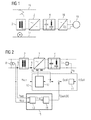
- FIG. 2 shows a control circuit for an exemplary embodiment of the invention with passive transducers 8 and 9.
- the starting point is a circuit arrangement according to FIG. 1.
- Current and voltage transformers 5, 6, 8, 9 become the actual values for the operation of the mains converter 3 detected relevant variables and fed to a controller 10 as measurement signals. These are detected with a measuring member 5 voltage u d of the intermediate circuit 4, the detected with a Transfoshunt 6 secondary current i Q of the transformer 2, the detected with a passive line current converter 9 primary network current i network and the detected with the passive line voltage converter 8 primary mains voltage u network . While the measuring elements 5 and 6 detect both direct component and alternating components, only the alternating component, but not any DC components, is transmitted by the passive converters 8 and 9.
- the regulator 10 based method is in the above-mentioned patent AT 224 196 disclosed.
- the regulator 10 includes a two-loop cascade control in which a voltage regulator 11 and pretends d by comparing the actual value of the intermediate circuit voltage with the desired setpoint voltage u d, set a desired current value i qsoll for the subordinate current control 12th
- the current control 12 controls, taking into account the actual value of the mains voltage u mains , based on the comparison of the measured actual current value i Q with the setpoint i Qsetpoint , the semiconductor switches of the controlled mains converter 3.
- the object of avoiding DC biasing of the transformer 2 is solved by a bias regulator 14 which calculates from the output signal b iN, 2 * of a bias detector 13 a DC setpoint i QSoll, DC as a correction value for the current setpoint i QSoll of the current controller 12.
- a bias regulator 14 which calculates from the output signal b iN, 2 * of a bias detector 13 a DC setpoint i QSoll, DC as a correction value for the current setpoint i QSoll of the current controller 12.
- the operation of the bias detector 13 is shown in FIG.
- the bias is detected by evaluating the 2nd harmonic of the mains current i network .
- the positive and negative half-wave of the mains current i network is strongly unbalanced. This manifests itself according to Fourier in pronounced even-numbered harmonics, especially in a well-measurable 2nd harmonic of the mains current.
- a next step 102 the phase angle ⁇ of the fundamental oscillator U net, 1 with respect to the real axis (a) of the DFT reference system is calculated by quadrant- correct evaluation of the arc tangent of the quotient b uN, 1 / a uN, 1 .
- the second mains current time vector is transformed into a coordinate system (a iN, 2 * + jb iN, 2 *) whose real axis points in the direction of the time hand of the mains voltage fundamental oscillation.
- the sign of the imaginary part sign (b iN, 2 *) gives the direction and the magnitude
- the output signal b iN , 2 * of the bias detector 13 can therefore be supplied directly to the bias controller 14 for detecting a counter to the bias secondary DC voltage setpoint i QSoll, DC .
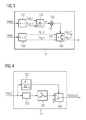
- FIG. 4 shows the function of the premagnetization controller 14.
- the detection signal b iN, 2 * is fed to a controller 200.
- a simple proportional P-controller can be used.
- the output signal of the controller 200 is limited in a subsequent limiter 201, so that the mains power converter 3, even with extremely large DC bias no inadmissibly high secondary currents i Q are set.
- the detection signal b iN, 2 * is compared with a threshold value (for example, 0.25% of the primary transformer nominal current ). Only when the bias exceeds this threshold is a switch 203 of the DC setpoint i QSoll, DC for the subordinate current control 12 switched from zero to the limited output value of the limiter 201. This ensures that the bias controller 14 does not begin to work until the bias of the transformer 2 has exceeded a certain minimum extent.
- FIG. 1 Another embodiment of the invention is shown in FIG. Based on the arrangement shown in FIG. 1, the mains current i network is measured with an active mains current transformer 9a. With this active transducer 9a, both the DC component and the AC component are detected. Accordingly, an analysis of harmonics is not required in an evaluation device 15a, and a correction value for the current setpoint i Qsetpoint of the current control 12 can be predefined in a simple manner by low-pass filtering of the measured value and a DC regulator.
- Another embodiment can be realized with a measuring device which detects only the DC component of the mains voltage u mains .
- This DC component of the mains voltage U mains is then proportional to the DC component of the line current i power corresponding to the ohmic resistance of the primary winding.
- this characteristic can be dispensed with a current transformer. Likewise, no low-pass filtering is required in the evaluation.
Landscapes
- Engineering & Computer Science (AREA)
- Power Engineering (AREA)
- Life Sciences & Earth Sciences (AREA)
- Sustainable Development (AREA)
- Sustainable Energy (AREA)
- Transportation (AREA)
- Mechanical Engineering (AREA)
- Electric Propulsion And Braking For Vehicles (AREA)
- Rectifiers (AREA)
Abstract
Description
- Die Erfindung betrifft ein Verfahren zur Regelung eines Netzstromrichters für Schienenfahrzeuge, wobei mittels eines Stromabnehmers, welcher eine Netzspannung eines einphasigen Wechselstromnetzes abgreift, dem Netzstromrichter über einen Transformator ein Netzstrom zugeführt wird und am Netzstromrichter ausgangsseitig eine konstante Zwischenkreisgleichspannung erzeugt wird. Des Weiteren betrifft die Erfindung eine Anordnung zur Durchführung des Verfahrens.
- Netzstromrichter für netzgespeiste Traktionsantriebe in Schienenfahrzeugen sind aus dem Stand der Technik seit langem bekannt (siehe Figur 1). Über einen Stromabnehmer wird die Netzspannung einer speisenden Oberleitung (z.B 15 kV, 16 2/3 Hz) abgegriffen und einer Primärwicklung eines Transformators zugeführt, wobei die Gleisanlagen das Bezugspotenzial bilden. Eine Sekundärwicklung des Transformators speist über den geregelten Netzstromrichter einen Spannungszwischenkreis mit einer durch die Regelung des Netzstromrichters konstant gehaltenen Zwischenkreisgleichspannung. Dabei ist der Netzstromrichter vorzugsweise als Vierquadrantensteller ausgebildet, da sich damit ein Strom weitgehend beliebiger Phasenlage zur Fahrdrahtspannung einstellen lässt.
- Ein an der Zwischenkreisgleichspannung liegender Maschinenstromrichter speist einen Drehstromasynchronmotor mit variabler Frequenz und Spannung, um im Motor bei der vorliegenden Drehzahl das gewünschte Antriebsmoment zu erzeugen.
- Durch verschiedene Einflussfaktoren treten im Netzstrom Harmonische auf, insbesondere durch eine Vormagnetisierung des Transformators mit einem damit verbundenen starken Anstieg des Magnetisierungsstromes. Diese Harmonischen sind vor allem dann unerwünscht, wenn bestimmte Frequenzen betroffen sind, welche von Bahnbetreibern in vielen Ländern für die Zugssicherungstechnik verwendet werden. So werden beispielsweise in Österreich und Deutschland Wechselspannungssignale mit einer Frequenz von 100 Hz zur Gleisüberwachung eingesetzt, wobei diese Frequenz der 6. Harmonischen in einem 16 2/3 Hz Netz entspricht.
- Dabei ist eine Strecke in Gleiskreise unterteilt, an deren Beginn eine 100 Hz Wechselspannung zwischen beiden Schienen anliegt. Am Ende eines Gleiskreises detektiert ein frequenzselektives Empfangsrelais die Spannung zwischen den Schienen. Liegt die eingespeiste Wechselspannung noch an, so zieht das Relais an und meldet den Gleiskreis als frei. Befindet sich jedoch ein Zug auf dem Gleiskreis, wird das eingespeiste Signal durch die Achsen des Zuges kurzgeschlossen und das Empfangsrelais fällt ab. Der Gleiskreis wird damit als besetzt gemeldet.
- Durch den Rückstrom eines Triebfahrzeugs kann es zu einer Beeinflussung der Funktion eines Gleiskreises kommen, wenn im Netzstrom eine 100 Hz Harmonische enthalten ist. Um Fehlfunktionen eines Gleiskreises zu vermeiden, darf der 100 Hz Störstrom des Triebfahrzeugs einen Grenzwert (z.B. 2A) nicht überschreiten. Deshalb ist nach dem Stand der Technik bei modernen Schienenfahrzeugen eine 100 Hz Störstromüberwachungseinrichtung vorgesehen, welche im Falle einer unzulässigen 100 Hz Störstromüberschreitung das Triebfahrzeug mittels eines Hauptschalters vom Netz trennt.
- Zur Unterdrückung der 100 Hz Harmonischen im Netzstrom ist aus der österreichischen Patentschrift
AT 408 296 B - Die grundlegende Regelung eines ein- oder mehrfachen Vierquadranten-Netzstromrichters ist dabei aus der österreichischen Patentschrift
AT 224 196
Zusätzlich ist in derAT 408 296 B - Ein weiteres Verfahren zur Vermeidung von 100 Hz Harmonischen ist aus der
DE 44 34 378 C1 bekannt. Dabei wird neben der 100 Hz Harmonischen auch die 50 Hz Stromoberschwingung durch eine in die Regelung eines Vierquadrantenstellers implementierte Störstromregelung unterdrückt. Eine primärseitige Vormagnetisierung des Transformators wird dabei nicht erfasst. - In der
JP 12 05 307 - Triebfahrzeuge können äußeren Bedingungen ausgesetzt sein, die zu einer primärseitigen Vormagnetisierung des Transformators führen. So ist beispielsweise bekannt, dass bei mit Raureif überzogenen Oberleitungen infolge niedriger Temperaturen Lichtbögen zwischen Oberleitung und Stromabnehmer auftreten. Die Eigenschaften dieser Lichtbögen sind dabei von der Polarität der Netzspannung abhängig, so dass der abgegriffene Netzstrom einen erheblichen Gleichstromanteil aufweist (siehe dazu L. Buhrkall: "DC components due to ice on the overhead contact wire of AC electrified railways", Elektrische Bahnen 103 (2005), Heft 8, Seite 380-389).
- Mit den aus dem Stand der Technik bekannten Verfahren ist eine Vermeidung von 100 Hz Stromoberschwingungen infolge hoher primärseitiger Vormagnetisierung - z.B. durch vereiste Oberleitungen - nicht möglich. Bei Triebfahrzeugen mit einer oben beschriebenen 100 Hz Störstromüberwachungseinrichtung führen derartige Betriebsbedingungen infolge zu hoher primärseitiger 100 Hz Stromoberschwingungen zum Abschalten des Hauptschalters und damit zum Ausfall des Triebfahrzeugs. Bei älteren Triebfahrzeugen ohne 100 Hz Störstromüberwachungseinrichtung kann es zu Fehlfunktionen der Zugsicherungstechnik kommen.
- Der Erfindung liegt die Aufgabe zugrunde, für ein Verfahren der eingangs genannten Art eine Verbesserung gegenüber dem Stand der Technik anzugeben.
- Erfindungsgemäß wird diese Aufgabe gelöst durch ein Verfahren zur Regelung eines Netzstromrichters für Schienenfahrzeuge, wobei mittels eines Stromabnehmers, welcher eine Netzspannung eines einphasigen Wechselstromnetzes abgreift, dem Netzstromrichter über einen Transformator ein Netzstrom zugeführt wird und am Netzstromrichter ausgangsseitig eine konstante Zwischenkreisgleichspannung erzeugt wird, wobei auf der Transformatorprimärseite ein Gleichstromanteil des Netzstromes mittels geeigneter Mess- und Auswerteeinrichtungen detektiert wird und wobei ein dem Gleichstromanteil entsprechender Gleichstromsollwert einem Stromsollwert einer sekundärseitigen Stromregelung des Netzstromrichters in der Weise überlagert wird, dass ein von der Stromregelung eingestellter sekundärseitiger Gleichstrom einer Vormagnetisierung des Transformators entgegenwirkt.
- Mit diesem Verfahren ist sichergestellt, dass der Transformator nicht durch primärseitige Gleichstromanteile des Netzstromes vormagnetisiert wird. Damit erfolgt kein Anstieg des Magnetisierungsstromes und es entstehen keine Harmonischen, die zum Ansprechen einer Störstromüberwachungseinrichtung führen könnten. Triebfahrzeuge mit Netzstromrichtern, die mit diesem Verfahren betrieben werden, sind somit ausfallssicherer als Treibfahrzeuge nach dem Stand der Technik, selbst bei vereister Oberleitung mit Lichtbogenbildung.
- Eine vorteilhafte Ausprägung der Erfindung sieht vor, dass der primärseitige Gleichstromanteil mittels eines aktiven Netzstromwandlers und einer geeigneten Auswerteeinrichtung detektiert wird. Mit einem derartigen Wandler wird ein primärseitiger Gleichstromanteil direkt erfasst und unmittelbar einer Regelung zur Vorgabe eines Gleichstromsollwertes zugeführt.
- Es ist aber auch vorteilhaft, wenn der primärseitige Gleichstromanteil mittels eines passiven Netzstromwandlers und eines passiven Netzspannungswandlers und einer geeigneten Auswerteeinrichtung durch eine Analyse der zweiten Oberschwingung des Netzstromes detektiert wird. Derartige passive Wandler sind in der Regel in einem Triebfahrzeug vorhanden, so dass keine zusätzlichen Wandler eingebaut werden müssen. Gegenüber dem Einsatz aktiver Wandler reduziert sich somit der Herstellungsaufwand. Ein weiterer Vorteil besteht darin, dass gegenüber aktiven Wandlern bei passiven Wandlern keine Offsetabgleich-Verfahren zur Justierung erforderlich sind.
- Dabei ist es von Vorteil, wenn in einem Vormagnetisierungsdetektor mittels einer Diskreten Fourier Transformation der komplexe Zeitzeiger der zweiten Oberschwingung des Netzstromes ermittelt wird und wenn das Ausmaß der Vormagnetisierung als Amplitude dieses Zeitzeigers bestimmt wird und wenn aus der Phasenlage der zweiten Oberschwingung des Netzstromes zur Grundschwingung der Netzspannung die Richtung der Vormagnetisierung bestimmt wird und wenn des Weiteren Ausmaß und Richtung der Vormagnetisierung einem Vormagnetisierungsregler zugeführt werden. In diesem Vormagnetisierungsregler wird daraus ein Gleichstromsollwert für die Stromregelung des Netzstromrichters bestimmt.
- Damit ist das Verfahren unter ausschließlicher Nutzung der für die Regelung des Netzstromrichters bereits vorhandenen Hardware durchführbar. Die für die Bestimmung der Vormagnetisierung angegebenen Verfahrensschritte können problemlos in der vorhandenen Hardware implementiert werden.
- Für eine Anordnung zur Durchführung des Verfahrens ist es vorteilhaft, wenn auf der Transformatorprimärseite geeignete Messeinrichtungen zur Erfassung des Netzstromes und der Netzspannung vorgesehen sind und wenn diese Messeinrichtungen mit einer Auswerteeinrichtung zur Vorgabe eines Gleichstromsollwertsignals verbunden sind. Dabei ist des Weiteren auf der Transformatorsekundärseite eine Messeinrichtung zur Erfassung des sekundärseitigen Stromes vorgesehen und ein Stromregler zur Ansteuerung des Netzstromrichters angeordnet, welchem ein aus einem Sollwertsignal, dem Gleichstromsollwertsignal und einem Messsignal des sekundärseitigen Stromes gebildetes Eingangssignal zugeführt ist.
- Mit dieser Anordnung ist sichergestellt, dass die Zwischenkreisspannung verlässlich auf einem konstanten Wert bleibt und dass alle Funktionen des Traktionsantriebes unbeeinflusst von der Vormagnetisierungsunterdrückung aufrecht sind.
- Dabei umfassen die Messeinrichtungen bei der ersten Ausführungsform einen aktiven Netzstromwandler und die Auswerteeinrichtung umfasst ein Tiefpassfilter und einen Gleichstromregler zur Vorgabe eines Gleichstromsollwertsignals.
- Bei der zweiten Ausführungsform umfassen die Messeinrichtungen einen passiven Netzstromwandler und einen passiven Netzspannungswandler und die Auswerteeinrichtung einen Vormagnetisierungsdetektor und einen Vormagnetisierungsregler zur Vorgabe eines Gleichstromsollwertsignals.
- Von Vorteil ist es des Weiteren, wenn der Netzstromrichter als Vierquadrantensteller ausgebildet ist. Der Netzstrom kann damit in einfacher Weise in Phase zur Netzspannung geregelt werden und es ist die Möglichkeit der Rückspeisung gegeben.
- Die Erfindung wird nachfolgend in beispielhafter Weise unter Bezugnahme auf die beigefügten Figuren erläutert. Es zeigen in schematischer Darstellung:
- Fig. 1
- Komponenten eines Traktionsantriebs
- Fig. 2
- Regelungsanordnung mit passiven Messwandlern
- Fig. 3
- Vormagnetisierungsdetektor
- Fig. 4
- Vormagnetisierungsregler
- Fig. 5
- Regelungsanordnung mit aktiven Messwandlern
- In Figur 1 sind die Komponenten eines elektrischen Traktionsantriebs für Schienenfahrzeuge, gespeist aus einem einphasigen Wechselstromnetz, als Prinzipschaltbild vereinfacht dargestellt. Über einen Stromabnehmer 1 wird die Wechselspannung der speisenden Oberleitung 16 abgegriffen und der Oberspannungswicklung des Traktions-Transformators 2 zugeführt. Die Sekundärwicklung des Transformators 2 speist über einen geregelten Netzstromrichter 3, der vorzugsweise als Vierquadrantensteller ausgeführt ist, einen Spannungszwischenkreis 4 mit einer durch die Regelung des Netzstromrichters 3 konstant gehaltenen Gleichspannung. Der an dieser Gleichspannung liegende Maschinenstromrichter 18 speist einen Drehstrom-Asynchronmotor 19 mit variabler Frequenz und Spannung, um im Drehstrom-Asynchronmotor 19 bei der vorliegenden Drehzahl das gewünschte Antriebsmoment zu erzeugen.
- Figur 2 zeigt einen Regelkreis für eine beispielhafte Ausprägung der Erfindung mit passiven Messwandlern 8 und 9. Ausgegangen wird dabei von einer Schaltungsanordnung gemäß Figur 1. Mit Strom- und Spannungswandlern 5, 6, 8, 9 werden die Istwerte der für den Betrieb des Netzstromrichters 3 relevanten Größen erfasst und einem Regler 10 als Messsignale zugeführt. Es sind dies die mit einem Messglied 5 erfasste Spannung ud des Zwischenkreises 4, der mit einem Transfoshunt 6 erfasste Sekundärstrom iQ des Transformators 2, der mit einem passiven Netzstromwandler 9 erfasste primäre Netzstrom iNetz sowie die mit dem passiven Netzspannungswandler 8 erfasste primäre Netzspannung uNetz. Während die Messglieder 5 und 6 sowohl Gleichanteil als auch Wechselanteile erfassen, wird von den passiven Wandlern 8 und 9 nur der Wechselanteil, nicht jedoch allfällige Gleichanteile übertragen.
- Das dem Regler 10 zugrunde liegende Verfahren ist in der oben genannten Patentschrift
AT 224 196 - Die Aufgabe der Vermeidung von Gleichstromvormagnetisierung des Transformators 2 wird durch einen Vormagnetisierungsregler 14 gelöst, der aus dem Ausgangssignal biN,2* eines Vormagnetisierungsdetektors 13 einen Gleichstromsollwert iQSoll,DC als Korrekturwert für den Stromsollwert iQSoll des Stromreglers 12 berechnet. Dadurch wird über die Sekundärwicklung des Transformators 2 ein der Vormagnetisierung entgegenwirkender Gleichstrom eingeprägt.
- Die Funktionsweise des Vormagnetisierungsdetektors 13 ist in Figur 3 dargestellt. Die Vormagnetisierung wird dabei durch Auswertung der 2. Oberschwingung des Netzstromes iNetz erfasst. Bei Vorliegen einer Gleichstromvormagnetisierung des Transformators 2 wird die positive und negative Halbwelle des Netzstromes iNetz stark unsymmetrisch. Dies äußert sich nach Fourier in ausgeprägten geradzahligen Harmonischen, insbesondere in einer gut messbaren 2. Oberschwingung des Netzstromes. Im Vormagnetisierungsdetektor 13 wird daher mittels einer Diskreten Fourier Transformation 100 der komplexe Zeitzeiger I Netz,2 = aiN,2 + j.biN,2 der zweiten Harmonischen (k=2) des gemessenen Netzstromsignals iNetz erfasst. Die Amplitude dieses Zeitzeigers ist ein Maß für das Ausmaß der vorliegenden Gleichstromvormagnetisierung im Transformator 2. Aus der Phasenlage der 2. Netzstromharmonischen in Relation zur Grundschwingung der Netzspannung uNetz wird auf die Richtung der Vormagnetisierung geschlossen. Dazu wird mit der Diskreten Fourier Transformation 101 aus dem Meßwert uNetz der Netzspannung der komplexe Zeitzeiger U Netz,1 = auN,1 + j.buN,1 der Grundschwingung (k=1) berechnet. In einem nächsten Schritt 102 wird die Phasenlage ϕ des Grundschwingungszeigers U Netz,1 in Bezug auf die reelle Achse (a) des DFT-Bezugssystems durch quadrantenrichtige Auswertung des Arcus-Tangens des Quotienten buN,1/auN,1 berechnet. Der ermittelte Winkel ϕ wird im nachfolgenden Schritt 103 mit dem Wert (-2) multipliziert: ϕ* = (-2) * ϕ. Der gemessene Zeitzeiger I Netz,2 der 2. Netzstromharmonischen wird in einem zusammenführenden Verfahrensschritt 104 um diesen korrigierten Winkel ϕ* gedreht: INetz,2* = INetz,2 * ej.ϕ*. Durch diese Drehung wird der 2. Netzstromzeitzeiger in ein Koordinatensystem transformiert (aiN,2* + j.biN,2*), dessen reelle Achse in Richtung des Zeitzeigers der Netzspannungsgrundschwingung zeigt. In diesem Koordinatensystem gibt das Vorzeichen des Imaginärteils sign (biN,2*) die Richtung und der Betrag |biN,2*| das Ausmaß der Vormagnetisierung des Transformators 2 an.
- Das Ausgangssignal biN,2* des Vormagnetisierungsdetektors 13 kann daher unmittelbar dem Vormagnetisierungsregler 14 zur Ermittlung eines der Vormagnetisierung entgegenwirkenden sekundären Gleichstromsollwertes iQSoll,DC zugeführt werden.
- In Figur 4 ist die Funktion des Vormagnetisierungsreglers 14 dargestellt. Das Detektionssignal biN,2* wird einem Regler 200 zugeführt. Im einfachsten Fall kann ein einfacher proportional wirkender P-Regler verwendet werden. Das Ausgangssignal des Reglers 200 wird in einem darauf folgenden Begrenzer 201 begrenzt, damit vom Netzstromrichter 3 auch bei extrem großer Gleichstromvormagnetisierung keine unzulässig hohen Sekundärströme iQ eingestellt werden. Mit einem Komparator 202 wird das Detektionssignal biN,2* mit einem Schwellwert (beispielsweise 0,25% des primären Transformatornennstromes) verglichen. Erst wenn die Vormagnetisierung diesen Schwellwert überschreitet, wird von einem Umschalter 203 der Gleichstromsollwert iQSoll, DC für die unterlagerte Stromregelung 12 von Null auf den begrenzten Ausgangswert des Begrenzers 201 umgeschaltet. Damit ist sichergestellt, dass der Vormagnetisierungsregler 14 erst zu arbeiten beginnt, wenn die Vormagnetisierung des Transformators 2 ein bestimmtes Mindestausmaß überschritten hat.
- Eine andere Ausprägung der Erfindung ist in Figur 5 dargestellt. Basierend auf der in Figur 1 dargestellten Anordnung wird dabei mit einem aktiven Netzstromwandler 9a der Netzstrom iNetz gemessen. Mit diesem aktiven Wandler 9a wird sowohl der Gleichanteil als auch der Wechselanteil erfasst. Dementsprechend ist in einer Auswerteeinrichtung 15a keine Analyse von Harmonischen erforderlich und ein Korrekturwert für den Stromsollwert iQSoll der Stromregelung 12 kann in einfacher Weise durch Tiefpass-Filterung des Messwertes und einen Gleichstromregler unmittelbar vorgegeben werden.
- Eine weitere Ausprägung ist mit einer Messeinrichtung realisierbar, welche ausschließlich den Gleichanteil der Netzspannung uNetz erfasst. Dieser Gleichanteil der Netzspannung uNetz ist dann entsprechend dem ohmschen Widerstand der Primärwicklung proportional zum Gleichstromanteil des Netzstromes iNetz. Bei dieser Ausprägung kann auf einen Stromwandler verzichtet werden. Ebenso ist in der Auswerteeinrichtung keine Tiefpass-Filterung erforderlich.
Claims (8)
- Verfahren zur Regelung eines Netzstromrichters (3) für Schienenfahrzeuge, wobei mittels eines Stromabnehmers (1), welcher eine Netzspannung (uNetz) eines einphasigen Wechselstromnetzes abgreift, dem Netzstromrichter (3) über einen Transformator (2) ein Netzstrom (iNetz) zugeführt wird und am Netzstromrichter (3) ausgangsseitig eine konstante Zwischenkreisgleichspannung (ud) erzeugt wird, dadurch gekennzeichnet, dass auf der Transformatorprimärseite ein Gleichstromanteil des Netzstromes (iNetz) mittels geeigneter Mess- und Auswerteeinrichtungen (8, 9, 15 bzw. 8a, 9a, 15a) detektiert wird und dass ein dem Gleichstromanteil entsprechender Gleichstromsollwert (iQSoll,DC) einem Stromsollwert (iQSoll) einer sekundärseitigen Stromregelung (12) des Netzstromrichters (3) in der Weise überlagert wird, dass ein von der Stromregelung (12) eingestellter sekundärseitiger Gleichstrom einer Vormagnetisierung des Transformators (2) entgegenwirkt.
- Verfahren nach Anspruch 1, dadurch gekennzeichnet, dass der primärseitige Gleichstromanteil mittels eines aktiven Netzstromwandlers (9a) und einer geeigneten Auswerteeinrichtung (15a) detektiert wird.
- Verfahren nach Anspruch 1, dadurch gekennzeichnet, dass der primärseitige Gleichstromanteil mittels eines passiven Netzstromwandlers (9) und eines passiven Netzspannungswandlers (8) und einer geeigneten Auswerteeinrichtung (15) durch eine Analyse der zweiten Oberschwingung des Netzstromes (iNetz) detektiert wird.
- Verfahren nach Anspruch 3, dadurch gekennzeichnet, dass in einem Vormagnetisierungsdetektor (13) mittels einer Diskreten Fourier Transformation der komplexe Zeitzeiger der zweiten Oberschwingung des Netzstromes (iNetz) ermittelt wird und dass das Ausmaß der Vormagnetisierung als Amplitude dieses Zeitzeigers bestimmt wird und dass aus der Phasenlage der zweiten Oberschwingung des Netzstromes (iNetz) zur Grundschwingung der Netzspannung (uNetz) die Richtung der Vormagnetisierung bestimmt wird und dass des Weiteren Ausmaß und Richtung der Vormagnetisierung einem Vormagnetisierungsregler (14) zugeführt werden und dass in diesem Vormagnetisierungsregler (14) daraus ein Gleichstromsollwert (iQSoll,DC) für die Stromregelung (12) des Netzstromrichters (3) bestimmt wird.
- Anordnung zur Durchführung eines Verfahrens nach einem der Ansprüche 1 bis 4, dadurch gekennzeichnet, dass auf der Transformatorprimärseite geeignete Messeinrichtungen (8, 9 bzw. 9a) zur Erfassung des Netzstromes (iNetz) und der Netzspannung (uNetz) vorgesehen sind und dass diese Messeinrichtungen (8, 9 bzw. 9a) mit einer Auswerteeinrichtung (15 bzw. 15a) zur Vorgabe eines Gleichstromsollwertsignals verbunden sind, dass auf der Transformatorsekundärseite eine Messeinrichtung (6) zur Erfassung des sekundärseitigen Stromes (iQ) vorgesehen ist und dass des Weiteren ein Stromregler (12) zur Ansteuerung des Netzstromrichters (3) angeordnet ist, welchem ein aus einem Sollwertsignal, dem Gleichstromsollwertsignal und einem Messsignal des sekundärseitigen Stromes (iQ) gebildetes Eingangssignal zugeführt ist.
- Anordnung nach Anspruch 5 zur Durchführung eines Verfahrens nach Anspruch 2, dadurch gekennzeichnet, dass die Messeinrichtung einen aktiven Netzstromwandler (9a) umfasst und dass die Auswerteeinrichtung (15a) ein Tiefpassfilter und einen Gleichstromregler zur Vorgabe eines Gleichstromsollwertsignals umfasst.
- Anordnung nach Anspruch 5 zur Durchführung eines Verfahrens nach Anspruch 3 oder 4, dadurch gekennzeichnet, dass die Messeinrichtungen einen passiven Netzstromwandler (9) und einen passiven Netzspannungswandler (8) umfassen und dass die Auswerteeinrichtung (15) einen Vormagnetisierungsdetektor (13) und einen Vormagnetisierungsregler (14) zur Vorgabe eines Gleichstromsollwertsignals umfasst.
- Anordnung nach einen der Ansprüche 5 bis 7, dadurch gekennzeichnet, dass der Netzstromsteller (3) als Vierquadrantensteller ausgebildet ist.
Applications Claiming Priority (1)
| Application Number | Priority Date | Filing Date | Title |
|---|---|---|---|
| AT0141006A AT504106B1 (de) | 2006-08-24 | 2006-08-24 | Verfahren zur regelung eines netzstromrichters für schienenfahrzeuge |
Publications (3)
| Publication Number | Publication Date |
|---|---|
| EP1892823A2 true EP1892823A2 (de) | 2008-02-27 |
| EP1892823A3 EP1892823A3 (de) | 2010-09-15 |
| EP1892823B1 EP1892823B1 (de) | 2012-02-29 |
Family
ID=38740186
Family Applications (1)
| Application Number | Title | Priority Date | Filing Date |
|---|---|---|---|
| EP07111151A Active EP1892823B1 (de) | 2006-08-24 | 2007-06-27 | Verfahren zur Regelung eines Netzstromrichters für Schienenfahrzeuge |
Country Status (4)
| Country | Link |
|---|---|
| EP (1) | EP1892823B1 (de) |
| AT (2) | AT504106B1 (de) |
| HR (1) | HRP20120439T1 (de) |
| RS (1) | RS52309B (de) |
Cited By (2)
| Publication number | Priority date | Publication date | Assignee | Title |
|---|---|---|---|---|
| CN112183004A (zh) * | 2020-09-30 | 2021-01-05 | 南方电网科学研究院有限责任公司 | 一种基于cdegs的电网感应电压分析方法 |
| CN112238792A (zh) * | 2019-07-19 | 2021-01-19 | 庞巴迪运输有限公司 | 通过车辆外部电流供给装置中的分离部位时运行轨道车辆 |
Family Cites Families (9)
| Publication number | Priority date | Publication date | Assignee | Title |
|---|---|---|---|---|
| JP2607471B2 (ja) * | 1986-03-17 | 1997-05-07 | 株式会社日立製作所 | パルス幅変調電力変換器の制御装置 |
| JPH0634579B2 (ja) * | 1986-03-28 | 1994-05-02 | 株式会社日立製作所 | Pwm電力変換器の制御装置 |
| JP2510510B2 (ja) * | 1986-03-11 | 1996-06-26 | 株式会社日立製作所 | Pwm電力変換器の制御装置 |
| JP2607648B2 (ja) * | 1988-11-24 | 1997-05-07 | 株式会社日立製作所 | 電力変換装置 |
| JP3186281B2 (ja) * | 1992-12-24 | 2001-07-11 | 株式会社日立製作所 | 交流電気車の制御装置 |
| JPH06233538A (ja) * | 1993-01-28 | 1994-08-19 | Mitsubishi Electric Corp | 交流電気車の制御装置 |
| JPH09140165A (ja) * | 1995-11-16 | 1997-05-27 | Hitachi Ltd | 電力変換器 |
| JPH10210606A (ja) * | 1997-01-22 | 1998-08-07 | Toshiba Corp | 電気車制御装置 |
| DE19728318C1 (de) * | 1997-06-27 | 1999-04-01 | Daimler Benz Ag | Verfahren zur Vermeidung der Sättigung von Einphasentransformatoren durch Gleichflüsse |
-
2006
- 2006-08-24 AT AT0141006A patent/AT504106B1/de not_active IP Right Cessation
-
2007
- 2007-06-27 EP EP07111151A patent/EP1892823B1/de active Active
- 2007-06-27 AT AT07111151T patent/ATE547837T1/de active
- 2007-06-27 RS RS20120164A patent/RS52309B/sr unknown
-
2012
- 2012-05-23 HR HRP20120439TT patent/HRP20120439T1/hr unknown
Cited By (3)
| Publication number | Priority date | Publication date | Assignee | Title |
|---|---|---|---|---|
| CN112238792A (zh) * | 2019-07-19 | 2021-01-19 | 庞巴迪运输有限公司 | 通过车辆外部电流供给装置中的分离部位时运行轨道车辆 |
| CN112183004A (zh) * | 2020-09-30 | 2021-01-05 | 南方电网科学研究院有限责任公司 | 一种基于cdegs的电网感应电压分析方法 |
| CN112183004B (zh) * | 2020-09-30 | 2024-02-13 | 南方电网科学研究院有限责任公司 | 一种基于cdegs的电网感应电压分析方法 |
Also Published As
| Publication number | Publication date |
|---|---|
| EP1892823B1 (de) | 2012-02-29 |
| HRP20120439T1 (hr) | 2012-06-30 |
| RS52309B (sr) | 2012-12-31 |
| AT504106B1 (de) | 2008-03-15 |
| EP1892823A3 (de) | 2010-09-15 |
| AT504106A4 (de) | 2008-03-15 |
| ATE547837T1 (de) | 2012-03-15 |
Similar Documents
| Publication | Publication Date | Title |
|---|---|---|
| EP3300199B1 (de) | Verfahren und einrichtung zum ansteuern eines leistungsschalters für ein elektrisches energieversorgungsnetz im nulldurchgang des stromes | |
| EP2917067B1 (de) | Messanordnung und verfahren für das erkennen einer wechselspannung als schienenpotential bei gleichstrombahnsystemen und anwendung der messanordnung | |
| WO2019007691A1 (de) | Unterbrechungsfreie stromversorgung | |
| AT402770B (de) | Verfahren zum überwachen eines drehstromnetzes auf eine abstimmungsänderung der erdschlusslöschspule | |
| EP3377911B1 (de) | Verfahren zum erkennen eines fehlers in einer generatoreinheit | |
| EP1892823B1 (de) | Verfahren zur Regelung eines Netzstromrichters für Schienenfahrzeuge | |
| EP3819162B1 (de) | Bahnenergieversorgungssystem und verfahren zur überwachung der integrität von mindestens einem rückanschlussleiter einer rückleitung für den bahnstrom | |
| EP0545026B1 (de) | Einrichtung zum sicheren automatischen Steuern des gegenseitigen Abstandes von Fahrzeugen | |
| DE102017212730A1 (de) | Verfahren und Einrichtung zur Fehlerortung entlang einer Energieversorgungsstrecke bei Gleichstromsystemen | |
| DE4330944C2 (de) | Verfahren zur prädiktiven Strombegrenzung bei einem statischen Bahnstrom-Umrichter | |
| EP0782783B1 (de) | Verfahren zur regelung eines als netzstromrichter fungierenden vierquadrantenstellers | |
| EP2091799B1 (de) | Vorrichtung zur kontaktlosen ermittlung des energiebedarfs eines weichenstellantriebs | |
| EP0993694B1 (de) | Überwachungsverfahren für einen stromkreis | |
| EP2383879A2 (de) | Verfahren und Synchronisationseinrichtung zur Synchronisierung von mindestens zwei RWA- und Lüftungsklappenantrieben | |
| WO2024068237A1 (de) | Überwachung der korrekten funktion eines hauptschalters eines schienenfahrzeugs | |
| AT397321B (de) | Schaltungsanordnung bei einem gesteuerten stromrichter | |
| DE102015225956A1 (de) | Vorrichtung und Verfahren zum Betreiben eines Triebfahrzeugs mit einer Wegrollsicherung und ein Triebfahrzeug mit einer solchen Wegrollsicherung | |
| DE102015223244A1 (de) | Vorrichtung und Verfahren zum Überwachen der Drehzahl eines Vakuumpumpenantriebs | |
| EP1493218B1 (de) | Not-aus-system für induktiv versorgte verbraucher | |
| WO2018086820A1 (de) | Unterwerkseinrichtung, bahnstromversorgungsanlage und verfahren zum speisen von wenigstens einer einphasigen versorgungsleitung | |
| EP1017157B1 (de) | Verfahren zur Regelung eines nichtharmonischen Anteils im Netzstrom eines netzseitigen Stromrichters und Vorrichtung zur Durchführung des Verfahrens | |
| EP3442106A1 (de) | Oberspannungssensorfreie antriebsvorrichtung | |
| DE3307970C2 (de) | Gleisstromkreis zur Gleisüberwachung in Eisenbahnsicherungsanlagen | |
| DE19638574A1 (de) | Stromversorgungsanordnung für Bahnfahrzeuge mit wenigstens einem gleichspannungsgespeisten, geregelten Stromrichter | |
| DE102021118335A1 (de) | Verfahren und AC-Onboard-Ladegerät zur Fehlerstromdetektion |
Legal Events
| Date | Code | Title | Description |
|---|---|---|---|
| PUAI | Public reference made under article 153(3) epc to a published international application that has entered the european phase |
Free format text: ORIGINAL CODE: 0009012 |
|
| AK | Designated contracting states |
Kind code of ref document: A2 Designated state(s): AT BE BG CH CY CZ DE DK EE ES FI FR GB GR HU IE IS IT LI LT LU LV MC MT NL PL PT RO SE SI SK TR |
|
| AX | Request for extension of the european patent |
Extension state: AL BA HR MK YU |
|
| 17P | Request for examination filed |
Effective date: 20100308 |
|
| PUAL | Search report despatched |
Free format text: ORIGINAL CODE: 0009013 |
|
| AK | Designated contracting states |
Kind code of ref document: A3 Designated state(s): AT BE BG CH CY CZ DE DK EE ES FI FR GB GR HU IE IS IT LI LT LU LV MC MT NL PL PT RO SE SI SK TR |
|
| AX | Request for extension of the european patent |
Extension state: AL BA HR MK RS |
|
| AKX | Designation fees paid |
Designated state(s): AT BE BG CH CY CZ DE DK EE ES FI FR GB GR HU IE IS IT LI LT LU LV MC MT NL PL PT RO SE SI SK TR |
|
| AXX | Extension fees paid |
Extension state: HR Payment date: 20100308 Extension state: BA Payment date: 20100308 Extension state: RS Payment date: 20100308 |
|
| RIC1 | Information provided on ipc code assigned before grant |
Ipc: H02M 7/219 20060101AFI20110722BHEP |
|
| GRAP | Despatch of communication of intention to grant a patent |
Free format text: ORIGINAL CODE: EPIDOSNIGR1 |
|
| GRAS | Grant fee paid |
Free format text: ORIGINAL CODE: EPIDOSNIGR3 |
|
| GRAA | (expected) grant |
Free format text: ORIGINAL CODE: 0009210 |
|
| RAP1 | Party data changed (applicant data changed or rights of an application transferred) |
Owner name: SIEMENS AKTIENGESELLSCHAFT OESTERREICH |
|
| AK | Designated contracting states |
Kind code of ref document: B1 Designated state(s): AT BE BG CH CY CZ DE DK EE ES FI FR GB GR HU IE IS IT LI LT LU LV MC MT NL PL PT RO SE SI SK TR |
|
| AX | Request for extension of the european patent |
Extension state: BA HR RS |
|
| REG | Reference to a national code |
Ref country code: GB Ref legal event code: FG4D Free format text: NOT ENGLISH Ref country code: CH Ref legal event code: EP |
|
| REG | Reference to a national code |
Ref country code: AT Ref legal event code: REF Ref document number: 547837 Country of ref document: AT Kind code of ref document: T Effective date: 20120315 |
|
| REG | Reference to a national code |
Ref country code: IE Ref legal event code: FG4D Free format text: LANGUAGE OF EP DOCUMENT: GERMAN |
|
| REG | Reference to a national code |
Ref country code: CH Ref legal event code: NV Representative=s name: SIEMENS SCHWEIZ AG |
|
| REG | Reference to a national code |
Ref country code: RO Ref legal event code: EPE |
|
| REG | Reference to a national code |
Ref country code: DE Ref legal event code: R096 Ref document number: 502007009368 Country of ref document: DE Effective date: 20120426 |
|
| REG | Reference to a national code |
Ref country code: HR Ref legal event code: TUEP Ref document number: P20120439 Country of ref document: HR |
|
| REG | Reference to a national code |
Ref country code: NL Ref legal event code: VDEP Effective date: 20120229 |
|
| REG | Reference to a national code |
Ref country code: HR Ref legal event code: T1PR Ref document number: P20120439 Country of ref document: HR |
|
| LTIE | Lt: invalidation of european patent or patent extension |
Effective date: 20120229 |
|
| PG25 | Lapsed in a contracting state [announced via postgrant information from national office to epo] |
Ref country code: NL Free format text: LAPSE BECAUSE OF FAILURE TO SUBMIT A TRANSLATION OF THE DESCRIPTION OR TO PAY THE FEE WITHIN THE PRESCRIBED TIME-LIMIT Effective date: 20120229 Ref country code: LT Free format text: LAPSE BECAUSE OF FAILURE TO SUBMIT A TRANSLATION OF THE DESCRIPTION OR TO PAY THE FEE WITHIN THE PRESCRIBED TIME-LIMIT Effective date: 20120229 Ref country code: IS Free format text: LAPSE BECAUSE OF FAILURE TO SUBMIT A TRANSLATION OF THE DESCRIPTION OR TO PAY THE FEE WITHIN THE PRESCRIBED TIME-LIMIT Effective date: 20120629 |
|
| PG25 | Lapsed in a contracting state [announced via postgrant information from national office to epo] |
Ref country code: PT Free format text: LAPSE BECAUSE OF FAILURE TO SUBMIT A TRANSLATION OF THE DESCRIPTION OR TO PAY THE FEE WITHIN THE PRESCRIBED TIME-LIMIT Effective date: 20120629 Ref country code: LV Free format text: LAPSE BECAUSE OF FAILURE TO SUBMIT A TRANSLATION OF THE DESCRIPTION OR TO PAY THE FEE WITHIN THE PRESCRIBED TIME-LIMIT Effective date: 20120229 Ref country code: GR Free format text: LAPSE BECAUSE OF FAILURE TO SUBMIT A TRANSLATION OF THE DESCRIPTION OR TO PAY THE FEE WITHIN THE PRESCRIBED TIME-LIMIT Effective date: 20120530 Ref country code: FI Free format text: LAPSE BECAUSE OF FAILURE TO SUBMIT A TRANSLATION OF THE DESCRIPTION OR TO PAY THE FEE WITHIN THE PRESCRIBED TIME-LIMIT Effective date: 20120229 |
|
| REG | Reference to a national code |
Ref country code: IE Ref legal event code: FD4D |
|
| PG25 | Lapsed in a contracting state [announced via postgrant information from national office to epo] |
Ref country code: CY Free format text: LAPSE BECAUSE OF FAILURE TO SUBMIT A TRANSLATION OF THE DESCRIPTION OR TO PAY THE FEE WITHIN THE PRESCRIBED TIME-LIMIT Effective date: 20120229 |
|
| PG25 | Lapsed in a contracting state [announced via postgrant information from national office to epo] |
Ref country code: CZ Free format text: LAPSE BECAUSE OF FAILURE TO SUBMIT A TRANSLATION OF THE DESCRIPTION OR TO PAY THE FEE WITHIN THE PRESCRIBED TIME-LIMIT Effective date: 20120229 Ref country code: DK Free format text: LAPSE BECAUSE OF FAILURE TO SUBMIT A TRANSLATION OF THE DESCRIPTION OR TO PAY THE FEE WITHIN THE PRESCRIBED TIME-LIMIT Effective date: 20120229 Ref country code: SE Free format text: LAPSE BECAUSE OF FAILURE TO SUBMIT A TRANSLATION OF THE DESCRIPTION OR TO PAY THE FEE WITHIN THE PRESCRIBED TIME-LIMIT Effective date: 20120229 Ref country code: EE Free format text: LAPSE BECAUSE OF FAILURE TO SUBMIT A TRANSLATION OF THE DESCRIPTION OR TO PAY THE FEE WITHIN THE PRESCRIBED TIME-LIMIT Effective date: 20120229 Ref country code: PL Free format text: LAPSE BECAUSE OF FAILURE TO SUBMIT A TRANSLATION OF THE DESCRIPTION OR TO PAY THE FEE WITHIN THE PRESCRIBED TIME-LIMIT Effective date: 20120229 Ref country code: SI Free format text: LAPSE BECAUSE OF FAILURE TO SUBMIT A TRANSLATION OF THE DESCRIPTION OR TO PAY THE FEE WITHIN THE PRESCRIBED TIME-LIMIT Effective date: 20120229 Ref country code: IE Free format text: LAPSE BECAUSE OF FAILURE TO SUBMIT A TRANSLATION OF THE DESCRIPTION OR TO PAY THE FEE WITHIN THE PRESCRIBED TIME-LIMIT Effective date: 20120229 |
|
| PG25 | Lapsed in a contracting state [announced via postgrant information from national office to epo] |
Ref country code: IT Free format text: LAPSE BECAUSE OF FAILURE TO SUBMIT A TRANSLATION OF THE DESCRIPTION OR TO PAY THE FEE WITHIN THE PRESCRIBED TIME-LIMIT Effective date: 20120229 Ref country code: SK Free format text: LAPSE BECAUSE OF FAILURE TO SUBMIT A TRANSLATION OF THE DESCRIPTION OR TO PAY THE FEE WITHIN THE PRESCRIBED TIME-LIMIT Effective date: 20120229 |
|
| BERE | Be: lapsed |
Owner name: SIEMENS A.G. OSTERREICH Effective date: 20120630 |
|
| PLBE | No opposition filed within time limit |
Free format text: ORIGINAL CODE: 0009261 |
|
| STAA | Information on the status of an ep patent application or granted ep patent |
Free format text: STATUS: NO OPPOSITION FILED WITHIN TIME LIMIT |
|
| PG25 | Lapsed in a contracting state [announced via postgrant information from national office to epo] |
Ref country code: MC Free format text: LAPSE BECAUSE OF NON-PAYMENT OF DUE FEES Effective date: 20120630 |
|
| 26N | No opposition filed |
Effective date: 20121130 |
|
| GBPC | Gb: european patent ceased through non-payment of renewal fee |
Effective date: 20120627 |
|
| REG | Reference to a national code |
Ref country code: DE Ref legal event code: R097 Ref document number: 502007009368 Country of ref document: DE Effective date: 20121130 |
|
| REG | Reference to a national code |
Ref country code: FR Ref legal event code: ST Effective date: 20130228 |
|
| PG25 | Lapsed in a contracting state [announced via postgrant information from national office to epo] |
Ref country code: BE Free format text: LAPSE BECAUSE OF NON-PAYMENT OF DUE FEES Effective date: 20120630 Ref country code: GB Free format text: LAPSE BECAUSE OF NON-PAYMENT OF DUE FEES Effective date: 20120627 Ref country code: FR Free format text: LAPSE BECAUSE OF NON-PAYMENT OF DUE FEES Effective date: 20120702 Ref country code: ES Free format text: LAPSE BECAUSE OF FAILURE TO SUBMIT A TRANSLATION OF THE DESCRIPTION OR TO PAY THE FEE WITHIN THE PRESCRIBED TIME-LIMIT Effective date: 20120609 |
|
| REG | Reference to a national code |
Ref country code: HU Ref legal event code: AG4A Ref document number: E015887 Country of ref document: HU |
|
| PG25 | Lapsed in a contracting state [announced via postgrant information from national office to epo] |
Ref country code: MT Free format text: LAPSE BECAUSE OF FAILURE TO SUBMIT A TRANSLATION OF THE DESCRIPTION OR TO PAY THE FEE WITHIN THE PRESCRIBED TIME-LIMIT Effective date: 20120229 |
|
| PG25 | Lapsed in a contracting state [announced via postgrant information from national office to epo] |
Ref country code: TR Free format text: LAPSE BECAUSE OF FAILURE TO SUBMIT A TRANSLATION OF THE DESCRIPTION OR TO PAY THE FEE WITHIN THE PRESCRIBED TIME-LIMIT Effective date: 20120229 |
|
| PG25 | Lapsed in a contracting state [announced via postgrant information from national office to epo] |
Ref country code: LU Free format text: LAPSE BECAUSE OF NON-PAYMENT OF DUE FEES Effective date: 20120627 |
|
| REG | Reference to a national code |
Ref country code: CH Ref legal event code: PUE Owner name: SIEMENS MOBILITY GMBH, AT Free format text: FORMER OWNER: SIEMENS AKTIENGESELLSCHAFT OESTERREICH, AT |
|
| REG | Reference to a national code |
Ref country code: DE Ref legal event code: R082 Ref document number: 502007009368 Country of ref document: DE Representative=s name: DEFFNER, ROLF, DR., DE Ref country code: DE Ref legal event code: R081 Ref document number: 502007009368 Country of ref document: DE Owner name: SIEMENS MOBILITY GMBH, AT Free format text: FORMER OWNER: SIEMENS AG OESTERREICH, WIEN, AT Ref country code: DE Ref legal event code: R081 Ref document number: 502007009368 Country of ref document: DE Owner name: SIEMENS MOBILITY AUSTRIA GMBH, AT Free format text: FORMER OWNER: SIEMENS AG OESTERREICH, WIEN, AT |
|
| REG | Reference to a national code |
Ref country code: HR Ref legal event code: ODRP Ref document number: P20120439 Country of ref document: HR Payment date: 20190612 Year of fee payment: 13 |
|
| REG | Reference to a national code |
Ref country code: AT Ref legal event code: PC Ref document number: 547837 Country of ref document: AT Kind code of ref document: T Owner name: SIEMENS MOBILITY GMBH, AT Effective date: 20190814 |
|
| REG | Reference to a national code |
Ref country code: DE Ref legal event code: R082 Ref document number: 502007009368 Country of ref document: DE Representative=s name: DEFFNER, ROLF, DR., DE Ref country code: DE Ref legal event code: R081 Ref document number: 502007009368 Country of ref document: DE Owner name: SIEMENS MOBILITY AUSTRIA GMBH, AT Free format text: FORMER OWNER: SIEMENS MOBILITY GMBH, WIEN, AT |
|
| REG | Reference to a national code |
Ref country code: CH Ref legal event code: PFA Owner name: SIEMENS MOBILITY AUSTRIA GMBH, AT Free format text: FORMER OWNER: SIEMENS MOBILITY GMBH, AT |
|
| REG | Reference to a national code |
Ref country code: HU Ref legal event code: FH1C Free format text: FORMER REPRESENTATIVE(S): MAK ANDRAS, SBGK SZABADALMI UEGYVIVOEI IRODA, HU Representative=s name: SBGK SZABADALMI UEGYVIVOEI IRODA, HU Ref country code: HU Ref legal event code: GB9C Owner name: SIEMENS MOBILITY AUSTRIA GMBH, AT Free format text: FORMER OWNER(S): SIEMENS AKTIENGESELLSCHAFT OESTERREICH, AT |
|
| REG | Reference to a national code |
Ref country code: HR Ref legal event code: PPPP Ref document number: P20120439 Country of ref document: HR Owner name: SIEMENS MOBILITY AUSTRIA GMBH, AT |
|
| REG | Reference to a national code |
Ref country code: HR Ref legal event code: ODRP Ref document number: P20120439 Country of ref document: HR Payment date: 20200623 Year of fee payment: 14 |
|
| REG | Reference to a national code |
Ref country code: HR Ref legal event code: ODRP Ref document number: P20120439 Country of ref document: HR Payment date: 20210621 Year of fee payment: 15 |
|
| PGFP | Annual fee paid to national office [announced via postgrant information from national office to epo] |
Ref country code: RO Payment date: 20210623 Year of fee payment: 15 |
|
| PGFP | Annual fee paid to national office [announced via postgrant information from national office to epo] |
Ref country code: BG Payment date: 20210618 Year of fee payment: 15 |
|
| REG | Reference to a national code |
Ref country code: AT Ref legal event code: HC Ref document number: 547837 Country of ref document: AT Kind code of ref document: T Owner name: SIEMENS MOBILITY AUSTRIA GMBH, AT Effective date: 20211108 |
|
| PGFP | Annual fee paid to national office [announced via postgrant information from national office to epo] |
Ref country code: HU Payment date: 20220819 Year of fee payment: 16 |
|
| PGFP | Annual fee paid to national office [announced via postgrant information from national office to epo] |
Ref country code: CH Payment date: 20220914 Year of fee payment: 16 |
|
| REG | Reference to a national code |
Ref country code: HR Ref legal event code: PBON Ref document number: P20120439 Country of ref document: HR Effective date: 20220627 |
|
| PG25 | Lapsed in a contracting state [announced via postgrant information from national office to epo] |
Ref country code: RO Free format text: LAPSE BECAUSE OF NON-PAYMENT OF DUE FEES Effective date: 20220627 |
|
| PGFP | Annual fee paid to national office [announced via postgrant information from national office to epo] |
Ref country code: DE Payment date: 20220630 Year of fee payment: 17 |
|
| PGFP | Annual fee paid to national office [announced via postgrant information from national office to epo] |
Ref country code: AT Payment date: 20230508 Year of fee payment: 17 |
|
| REG | Reference to a national code |
Ref country code: CH Ref legal event code: PL |
|
| PG25 | Lapsed in a contracting state [announced via postgrant information from national office to epo] |
Ref country code: HU Free format text: LAPSE BECAUSE OF NON-PAYMENT OF DUE FEES Effective date: 20230628 Ref country code: CH Free format text: LAPSE BECAUSE OF NON-PAYMENT OF DUE FEES Effective date: 20230630 |
|
| PG25 | Lapsed in a contracting state [announced via postgrant information from national office to epo] |
Ref country code: BG Free format text: LAPSE BECAUSE OF NON-PAYMENT OF DUE FEES Effective date: 20220627 |
|
| REG | Reference to a national code |
Ref country code: DE Ref legal event code: R119 Ref document number: 502007009368 Country of ref document: DE |
|
| REG | Reference to a national code |
Ref country code: AT Ref legal event code: MM01 Ref document number: 547837 Country of ref document: AT Kind code of ref document: T Effective date: 20240627 |
|
| PG25 | Lapsed in a contracting state [announced via postgrant information from national office to epo] |
Ref country code: DE Free format text: LAPSE BECAUSE OF NON-PAYMENT OF DUE FEES Effective date: 20250101 |
|
| PG25 | Lapsed in a contracting state [announced via postgrant information from national office to epo] |
Ref country code: AT Free format text: LAPSE BECAUSE OF NON-PAYMENT OF DUE FEES Effective date: 20240627 |