EP1892823A2 - Procédé destiné à la régulation d'un convertisseur de puissance côté réseau pour véhicules sur rail - Google Patents
Procédé destiné à la régulation d'un convertisseur de puissance côté réseau pour véhicules sur rail Download PDFInfo
- Publication number
- EP1892823A2 EP1892823A2 EP07111151A EP07111151A EP1892823A2 EP 1892823 A2 EP1892823 A2 EP 1892823A2 EP 07111151 A EP07111151 A EP 07111151A EP 07111151 A EP07111151 A EP 07111151A EP 1892823 A2 EP1892823 A2 EP 1892823A2
- Authority
- EP
- European Patent Office
- Prior art keywords
- mains
- current
- bias
- converter
- transformer
- Prior art date
- Legal status (The legal status is an assumption and is not a legal conclusion. Google has not performed a legal analysis and makes no representation as to the accuracy of the status listed.)
- Granted
Links
- 238000000034 method Methods 0.000 title claims abstract description 28
- 230000001105 regulatory effect Effects 0.000 title abstract description 4
- 238000011156 evaluation Methods 0.000 claims description 15
- 238000005259 measurement Methods 0.000 claims description 3
- 238000004458 analytical method Methods 0.000 claims description 2
- 230000005415 magnetization Effects 0.000 abstract 1
- 238000004804 winding Methods 0.000 description 6
- 230000033228 biological regulation Effects 0.000 description 5
- 230000001276 controlling effect Effects 0.000 description 3
- 238000012806 monitoring device Methods 0.000 description 3
- 238000012937 correction Methods 0.000 description 2
- 238000001514 detection method Methods 0.000 description 2
- 238000005516 engineering process Methods 0.000 description 2
- 238000001914 filtration Methods 0.000 description 2
- 230000003137 locomotive effect Effects 0.000 description 2
- 230000007257 malfunction Effects 0.000 description 2
- 230000009466 transformation Effects 0.000 description 2
- 230000008901 benefit Effects 0.000 description 1
- 230000001419 dependent effect Effects 0.000 description 1
- 238000010586 diagram Methods 0.000 description 1
- 230000006872 improvement Effects 0.000 description 1
- 238000004519 manufacturing process Methods 0.000 description 1
- 238000012544 monitoring process Methods 0.000 description 1
- 230000010355 oscillation Effects 0.000 description 1
- 230000004044 response Effects 0.000 description 1
- 239000004065 semiconductor Substances 0.000 description 1
- 230000003595 spectral effect Effects 0.000 description 1
- 230000001629 suppression Effects 0.000 description 1
Images

Classifications
-
- H—ELECTRICITY
- H02—GENERATION; CONVERSION OR DISTRIBUTION OF ELECTRIC POWER
- H02M—APPARATUS FOR CONVERSION BETWEEN AC AND AC, BETWEEN AC AND DC, OR BETWEEN DC AND DC, AND FOR USE WITH MAINS OR SIMILAR POWER SUPPLY SYSTEMS; CONVERSION OF DC OR AC INPUT POWER INTO SURGE OUTPUT POWER; CONTROL OR REGULATION THEREOF
- H02M7/00—Conversion of AC power input into DC power output; Conversion of DC power input into AC power output
- H02M7/02—Conversion of AC power input into DC power output without possibility of reversal
- H02M7/04—Conversion of AC power input into DC power output without possibility of reversal by static converters
- H02M7/12—Conversion of AC power input into DC power output without possibility of reversal by static converters using discharge tubes with control electrode or semiconductor devices with control electrode
- H02M7/21—Conversion of AC power input into DC power output without possibility of reversal by static converters using discharge tubes with control electrode or semiconductor devices with control electrode using devices of a triode or transistor type requiring continuous application of a control signal
- H02M7/217—Conversion of AC power input into DC power output without possibility of reversal by static converters using discharge tubes with control electrode or semiconductor devices with control electrode using devices of a triode or transistor type requiring continuous application of a control signal using semiconductor devices only
- H02M7/219—Conversion of AC power input into DC power output without possibility of reversal by static converters using discharge tubes with control electrode or semiconductor devices with control electrode using devices of a triode or transistor type requiring continuous application of a control signal using semiconductor devices only in a bridge configuration
-
- B—PERFORMING OPERATIONS; TRANSPORTING
- B60—VEHICLES IN GENERAL
- B60L—PROPULSION OF ELECTRICALLY-PROPELLED VEHICLES; SUPPLYING ELECTRIC POWER FOR AUXILIARY EQUIPMENT OF ELECTRICALLY-PROPELLED VEHICLES; ELECTRODYNAMIC BRAKE SYSTEMS FOR VEHICLES IN GENERAL; MAGNETIC SUSPENSION OR LEVITATION FOR VEHICLES; MONITORING OPERATING VARIABLES OF ELECTRICALLY-PROPELLED VEHICLES; ELECTRIC SAFETY DEVICES FOR ELECTRICALLY-PROPELLED VEHICLES
- B60L3/00—Electric devices on electrically-propelled vehicles for safety purposes; Monitoring operating variables, e.g. speed, deceleration or energy consumption
- B60L3/0023—Detecting, eliminating, remedying or compensating for drive train abnormalities, e.g. failures within the drive train
- B60L3/003—Detecting, eliminating, remedying or compensating for drive train abnormalities, e.g. failures within the drive train relating to inverters
-
- B—PERFORMING OPERATIONS; TRANSPORTING
- B60—VEHICLES IN GENERAL
- B60L—PROPULSION OF ELECTRICALLY-PROPELLED VEHICLES; SUPPLYING ELECTRIC POWER FOR AUXILIARY EQUIPMENT OF ELECTRICALLY-PROPELLED VEHICLES; ELECTRODYNAMIC BRAKE SYSTEMS FOR VEHICLES IN GENERAL; MAGNETIC SUSPENSION OR LEVITATION FOR VEHICLES; MONITORING OPERATING VARIABLES OF ELECTRICALLY-PROPELLED VEHICLES; ELECTRIC SAFETY DEVICES FOR ELECTRICALLY-PROPELLED VEHICLES
- B60L9/00—Electric propulsion with power supply external to the vehicle
-
- H—ELECTRICITY
- H02—GENERATION; CONVERSION OR DISTRIBUTION OF ELECTRIC POWER
- H02M—APPARATUS FOR CONVERSION BETWEEN AC AND AC, BETWEEN AC AND DC, OR BETWEEN DC AND DC, AND FOR USE WITH MAINS OR SIMILAR POWER SUPPLY SYSTEMS; CONVERSION OF DC OR AC INPUT POWER INTO SURGE OUTPUT POWER; CONTROL OR REGULATION THEREOF
- H02M1/00—Details of apparatus for conversion
- H02M1/40—Means for preventing magnetic saturation
-
- B—PERFORMING OPERATIONS; TRANSPORTING
- B60—VEHICLES IN GENERAL
- B60L—PROPULSION OF ELECTRICALLY-PROPELLED VEHICLES; SUPPLYING ELECTRIC POWER FOR AUXILIARY EQUIPMENT OF ELECTRICALLY-PROPELLED VEHICLES; ELECTRODYNAMIC BRAKE SYSTEMS FOR VEHICLES IN GENERAL; MAGNETIC SUSPENSION OR LEVITATION FOR VEHICLES; MONITORING OPERATING VARIABLES OF ELECTRICALLY-PROPELLED VEHICLES; ELECTRIC SAFETY DEVICES FOR ELECTRICALLY-PROPELLED VEHICLES
- B60L2200/00—Type of vehicles
- B60L2200/26—Rail vehicles
Definitions
- the invention relates to a method for controlling a mains converter for rail vehicles, wherein by means of a current collector, which picks up a mains voltage of a single-phase AC mains, the mains converter via a transformer, a mains power is supplied to the power converter and the output side, a constant DC link voltage is generated. Furthermore, the invention relates to an arrangement for carrying out the method.
- Mains power converters for mains-powered traction drives in rail vehicles have long been known from the prior art (see FIG. 1).
- the mains voltage of a feeding catenary for example, 15 kV, 16 2/3 Hz
- the track systems form the reference potential.
- a secondary winding of the transformer feeds via the regulated mains converter a voltage intermediate circuit with a held constant by the regulation of the mains rectifier DC link voltage.
- the power converter is preferably designed as a four-quadrant controller, as this allows a current largely arbitrary phase position to the contact wire voltage can be adjusted.
- a DC link voltage generator feeds a variable frequency, voltage three phase asynchronous motor to produce the desired drive torque in the motor at the present speed.
- harmonics occur in the mains current, in particular due to a premagnetization of the transformer with an associated strong increase of the magnetizing current. These harmonics are particularly undesirable when certain frequencies are affected, which are used by train operators in many countries for the train safety technology. For example, in Austria and Germany alternating voltage signals with a frequency of 100 Hz are used for track monitoring, whereby this frequency corresponds to the 6th harmonic in a 16 2/3 Hz network.
- a track is divided into track circuits, at the beginning of a 100 Hz alternating voltage between the two rails is applied.
- a frequency selective receive relay detects the voltage between the rails. If the supplied AC voltage is still present, the relay picks up and signals the track circuit as free. However, if there is a train on the track, the fed signal is short-circuited by the axles of the train and the receiving relay drops. The track circle is thus reported as occupied.
- the return current of a traction vehicle can influence the function of a track circuit if the mains current contains a 100 Hz harmonic.
- the traction motor's 100 Hz noise current must not exceed a limit value (e.g., 2A). Therefore, according to the state of the art in modern rail vehicles, a 100 Hz interference current monitoring device is provided, which separates the traction vehicle by means of a main switch from the grid in the event of an impermissible 100 Hz interference current crossing.
- Another method of avoiding 100 Hz harmonics is from the DE 44 34 378 C1 known.
- the 50 Hz current harmonic is suppressed by a disturbance current control implemented in the regulation of a four-quadrant controller. A primary-side bias of the transformer is not detected.
- a method of detecting a DC bias of the transformer of a vehicle operating on a single-phase AC mains with which a primary-side DC bias can be detected is based on the rectification of the measured primary current and a downstream bandpass filter, which is tuned to the mains frequency. If there is no DC bias, then the signal contains only even harmonics, but no spectral component at the line frequency. The output signal of the bandpass filter is therefore zero. If DC biasing is present, then the signal will include a power frequency component after rectification, which may be measured at the output of the bandpass filter, after half-wave unbalance. A measure to avoid a primary-side bias is not specified.
- Traction vehicles can be exposed to external conditions that lead to a primary-side bias of the transformer. It is known, for example, that in hoarfrost-covered overhead lines due to low temperatures, arcs occur between the overhead line and the current collector. The properties of these arcs are dependent on the polarity of the mains voltage, so that the tapped mains current has a significant DC component (see L. Buhrkall: "DC components due to ice on the overhead contact wire of AC electrified railways", Electric webs 103 (2005), No. 8, pages 380-389 ).
- the invention has for its object to provide an improvement over the prior art for a method of the type mentioned.
- this object is achieved by a method for controlling a mains converter for rail vehicles, by means of a current collector, which picks up a mains voltage of a single-phase AC mains, the mains converter via a transformer is supplied to a mains and the power converter on the output side, a constant DC link voltage is generated, on the transformer primary side, a DC component of the mains current is detected by means of suitable measuring and evaluation and wherein a direct current component corresponding direct current component is superimposed on a current setpoint secondary current control of the mains converter in such a way that counteracted by the current control secondary side DC counteracts a bias of the transformer.
- An advantageous embodiment of the invention provides that the primary-side DC component is detected by means of an active mains current transformer and a suitable evaluation device. With such a converter, a primary-side DC component is detected directly and fed directly to a controller for setting a DC nominal value.
- the primary-side DC component is detected by means of a passive mains current transformer and a passive mains voltage converter and a suitable evaluation device by analyzing the second harmonic of the mains current.
- passive transducers are usually present in a locomotive, so that no additional transducers must be installed. Compared to the use of active converter thus reduces the production cost.
- Another Advantage is that compared to active transducers in passive transducers no offset adjustment procedures are required for adjustment.
- the complex time vector of the second harmonic of the mains current is determined in a bias detector by means of a discrete Fourier transform and if the extent of the bias is determined as the amplitude of this time hand and if from the phase position of the second harmonic of the mains current to the fundamental Mains voltage, the direction of the bias is determined and further when the amount and direction of the bias are fed to a bias regulator.
- a DC setpoint is determined for the current regulation of the mains converter.
- a measuring device for detecting the secondary-side current is provided on the transformer secondary side, and a current controller for controlling the mains converter is arranged, to which an input signal formed from a setpoint signal, the DC setpoint signal and a measurement signal of the secondary-side current is supplied.
- This arrangement ensures that the DC link voltage remains reliably at a constant value and that all functions of the traction drive are maintained unaffected by the bias suppression.
- the measuring devices in the first embodiment comprise an active mains current transformer and the evaluation device comprises a low-pass filter and a DC regulator for specifying a DC nominal value signal.
- the measuring devices comprise a passive mains current transformer and a passive mains voltage converter and the evaluation device comprises a bias detector and a bias controller for inputting a DC setpoint signal.
- the mains converter is designed as a four-quadrant controller.
- the mains current can thus be controlled in a simple manner in phase to the mains voltage and there is the possibility of feeding back.
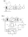
- FIG. 1 the components of an electric traction drive for rail vehicles, fed from a single-phase AC power system, shown simplified as a schematic diagram.
- a pantograph 1 the AC voltage of the feeding catenary 16 is tapped and the high-voltage winding of the traction transformer 2 fed.
- the secondary winding of the transformer 2 feeds via a regulated mains converter 3, which is preferably designed as a four-quadrant controller, a voltage intermediate circuit 4 with a held constant by the regulation of the mains converter 3 DC voltage.
- the machine power converter 18 at this DC voltage feeds a three-phase asynchronous motor 19 of variable frequency and voltage to produce the desired drive torque in the three-phase asynchronous motor 19 at the present speed.
- FIG. 2 shows a control circuit for an exemplary embodiment of the invention with passive transducers 8 and 9.
- the starting point is a circuit arrangement according to FIG. 1.
- Current and voltage transformers 5, 6, 8, 9 become the actual values for the operation of the mains converter 3 detected relevant variables and fed to a controller 10 as measurement signals. These are detected with a measuring member 5 voltage u d of the intermediate circuit 4, the detected with a Transfoshunt 6 secondary current i Q of the transformer 2, the detected with a passive line current converter 9 primary network current i network and the detected with the passive line voltage converter 8 primary mains voltage u network . While the measuring elements 5 and 6 detect both direct component and alternating components, only the alternating component, but not any DC components, is transmitted by the passive converters 8 and 9.
- the regulator 10 based method is in the above-mentioned patent AT 224 196 disclosed.
- the regulator 10 includes a two-loop cascade control in which a voltage regulator 11 and pretends d by comparing the actual value of the intermediate circuit voltage with the desired setpoint voltage u d, set a desired current value i qsoll for the subordinate current control 12th
- the current control 12 controls, taking into account the actual value of the mains voltage u mains , based on the comparison of the measured actual current value i Q with the setpoint i Qsetpoint , the semiconductor switches of the controlled mains converter 3.
- the object of avoiding DC biasing of the transformer 2 is solved by a bias regulator 14 which calculates from the output signal b iN, 2 * of a bias detector 13 a DC setpoint i QSoll, DC as a correction value for the current setpoint i QSoll of the current controller 12.
- a bias regulator 14 which calculates from the output signal b iN, 2 * of a bias detector 13 a DC setpoint i QSoll, DC as a correction value for the current setpoint i QSoll of the current controller 12.
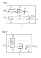
- the operation of the bias detector 13 is shown in FIG.
- the bias is detected by evaluating the 2nd harmonic of the mains current i network .
- the positive and negative half-wave of the mains current i network is strongly unbalanced. This manifests itself according to Fourier in pronounced even-numbered harmonics, especially in a well-measurable 2nd harmonic of the mains current.
- a next step 102 the phase angle ⁇ of the fundamental oscillator U net, 1 with respect to the real axis (a) of the DFT reference system is calculated by quadrant- correct evaluation of the arc tangent of the quotient b uN, 1 / a uN, 1 .
- the second mains current time vector is transformed into a coordinate system (a iN, 2 * + jb iN, 2 *) whose real axis points in the direction of the time hand of the mains voltage fundamental oscillation.
- the sign of the imaginary part sign (b iN, 2 *) gives the direction and the magnitude
- the output signal b iN , 2 * of the bias detector 13 can therefore be supplied directly to the bias controller 14 for detecting a counter to the bias secondary DC voltage setpoint i QSoll, DC .
- FIG. 4 shows the function of the premagnetization controller 14.
- the detection signal b iN, 2 * is fed to a controller 200.
- a simple proportional P-controller can be used.
- the output signal of the controller 200 is limited in a subsequent limiter 201, so that the mains power converter 3, even with extremely large DC bias no inadmissibly high secondary currents i Q are set.
- the detection signal b iN, 2 * is compared with a threshold value (for example, 0.25% of the primary transformer nominal current ). Only when the bias exceeds this threshold is a switch 203 of the DC setpoint i QSoll, DC for the subordinate current control 12 switched from zero to the limited output value of the limiter 201. This ensures that the bias controller 14 does not begin to work until the bias of the transformer 2 has exceeded a certain minimum extent.
- FIG. 1 Another embodiment of the invention is shown in FIG. Based on the arrangement shown in FIG. 1, the mains current i network is measured with an active mains current transformer 9a. With this active transducer 9a, both the DC component and the AC component are detected. Accordingly, an analysis of harmonics is not required in an evaluation device 15a, and a correction value for the current setpoint i Qsetpoint of the current control 12 can be predefined in a simple manner by low-pass filtering of the measured value and a DC regulator.
- Another embodiment can be realized with a measuring device which detects only the DC component of the mains voltage u mains .
- This DC component of the mains voltage U mains is then proportional to the DC component of the line current i power corresponding to the ohmic resistance of the primary winding.
- this characteristic can be dispensed with a current transformer. Likewise, no low-pass filtering is required in the evaluation.
Landscapes
- Engineering & Computer Science (AREA)
- Power Engineering (AREA)
- Life Sciences & Earth Sciences (AREA)
- Sustainable Development (AREA)
- Sustainable Energy (AREA)
- Transportation (AREA)
- Mechanical Engineering (AREA)
- Electric Propulsion And Braking For Vehicles (AREA)
- Rectifiers (AREA)
Applications Claiming Priority (1)
| Application Number | Priority Date | Filing Date | Title |
|---|---|---|---|
| AT0141006A AT504106B1 (de) | 2006-08-24 | 2006-08-24 | Verfahren zur regelung eines netzstromrichters für schienenfahrzeuge |
Publications (3)
| Publication Number | Publication Date |
|---|---|
| EP1892823A2 true EP1892823A2 (fr) | 2008-02-27 |
| EP1892823A3 EP1892823A3 (fr) | 2010-09-15 |
| EP1892823B1 EP1892823B1 (fr) | 2012-02-29 |
Family
ID=38740186
Family Applications (1)
| Application Number | Title | Priority Date | Filing Date |
|---|---|---|---|
| EP07111151A Active EP1892823B1 (fr) | 2006-08-24 | 2007-06-27 | Procédé destiné à la régulation d'un convertisseur de puissance côté réseau pour véhicules sur rail |
Country Status (4)
| Country | Link |
|---|---|
| EP (1) | EP1892823B1 (fr) |
| AT (2) | AT504106B1 (fr) |
| HR (1) | HRP20120439T1 (fr) |
| RS (1) | RS52309B (fr) |
Cited By (2)
| Publication number | Priority date | Publication date | Assignee | Title |
|---|---|---|---|---|
| CN112183004A (zh) * | 2020-09-30 | 2021-01-05 | 南方电网科学研究院有限责任公司 | 一种基于cdegs的电网感应电压分析方法 |
| CN112238792A (zh) * | 2019-07-19 | 2021-01-19 | 庞巴迪运输有限公司 | 通过车辆外部电流供给装置中的分离部位时运行轨道车辆 |
Family Cites Families (9)
| Publication number | Priority date | Publication date | Assignee | Title |
|---|---|---|---|---|
| JP2607471B2 (ja) * | 1986-03-17 | 1997-05-07 | 株式会社日立製作所 | パルス幅変調電力変換器の制御装置 |
| JPH0634579B2 (ja) * | 1986-03-28 | 1994-05-02 | 株式会社日立製作所 | Pwm電力変換器の制御装置 |
| JP2510510B2 (ja) * | 1986-03-11 | 1996-06-26 | 株式会社日立製作所 | Pwm電力変換器の制御装置 |
| JP2607648B2 (ja) * | 1988-11-24 | 1997-05-07 | 株式会社日立製作所 | 電力変換装置 |
| JP3186281B2 (ja) * | 1992-12-24 | 2001-07-11 | 株式会社日立製作所 | 交流電気車の制御装置 |
| JPH06233538A (ja) * | 1993-01-28 | 1994-08-19 | Mitsubishi Electric Corp | 交流電気車の制御装置 |
| JPH09140165A (ja) * | 1995-11-16 | 1997-05-27 | Hitachi Ltd | 電力変換器 |
| JPH10210606A (ja) * | 1997-01-22 | 1998-08-07 | Toshiba Corp | 電気車制御装置 |
| DE19728318C1 (de) * | 1997-06-27 | 1999-04-01 | Daimler Benz Ag | Verfahren zur Vermeidung der Sättigung von Einphasentransformatoren durch Gleichflüsse |
-
2006
- 2006-08-24 AT AT0141006A patent/AT504106B1/de not_active IP Right Cessation
-
2007
- 2007-06-27 EP EP07111151A patent/EP1892823B1/fr active Active
- 2007-06-27 AT AT07111151T patent/ATE547837T1/de active
- 2007-06-27 RS RS20120164A patent/RS52309B/sr unknown
-
2012
- 2012-05-23 HR HRP20120439TT patent/HRP20120439T1/hr unknown
Cited By (3)
| Publication number | Priority date | Publication date | Assignee | Title |
|---|---|---|---|---|
| CN112238792A (zh) * | 2019-07-19 | 2021-01-19 | 庞巴迪运输有限公司 | 通过车辆外部电流供给装置中的分离部位时运行轨道车辆 |
| CN112183004A (zh) * | 2020-09-30 | 2021-01-05 | 南方电网科学研究院有限责任公司 | 一种基于cdegs的电网感应电压分析方法 |
| CN112183004B (zh) * | 2020-09-30 | 2024-02-13 | 南方电网科学研究院有限责任公司 | 一种基于cdegs的电网感应电压分析方法 |
Also Published As
| Publication number | Publication date |
|---|---|
| EP1892823B1 (fr) | 2012-02-29 |
| HRP20120439T1 (hr) | 2012-06-30 |
| RS52309B (sr) | 2012-12-31 |
| AT504106B1 (de) | 2008-03-15 |
| EP1892823A3 (fr) | 2010-09-15 |
| AT504106A4 (de) | 2008-03-15 |
| ATE547837T1 (de) | 2012-03-15 |
Similar Documents
| Publication | Publication Date | Title |
|---|---|---|
| EP3300199B1 (fr) | Procédé et dispositif destinés à contrôler un disjoncteur pour un réseau d'alimentation en énergie électrique lors du passage à zéro du courant | |
| EP2917067B1 (fr) | Système de mesure, procédé de détection d'une tension alternative servant de potentiel de rail dans des systèmes ferroviaires à courant continu et utilisation du système de mesure | |
| WO2019007691A1 (fr) | Alimentation de courant sans interruption | |
| AT402770B (de) | Verfahren zum überwachen eines drehstromnetzes auf eine abstimmungsänderung der erdschlusslöschspule | |
| EP3377911B1 (fr) | Procédé de détection d'une défaillance dans un groupe générateur | |
| EP1892823B1 (fr) | Procédé destiné à la régulation d'un convertisseur de puissance côté réseau pour véhicules sur rail | |
| EP3819162B1 (fr) | Système d'alimentation électrique ferroviaire et procédé de surveillance de l'intégrité d'au moins un conducteur de raccordement de retour d'une connection de retour pour le courant de traction | |
| EP0545026B1 (fr) | Système de commande automatique sûre de la distance mutuelle de véhicules. | |
| DE102017212730A1 (de) | Verfahren und Einrichtung zur Fehlerortung entlang einer Energieversorgungsstrecke bei Gleichstromsystemen | |
| DE4330944C2 (de) | Verfahren zur prädiktiven Strombegrenzung bei einem statischen Bahnstrom-Umrichter | |
| EP0782783B1 (fr) | Procede de regulation d'un regulateur a quatre quadrants utile comme convertisseur de puissance reseau | |
| EP2091799B1 (fr) | Dispositif destiné à la détermination sans contact de la consommation en énergie d'un mécanisme de manoeuvre d'aiguillage | |
| EP0993694B1 (fr) | Procede de controle pour circuit electrique | |
| EP2383879A2 (fr) | Procédé et dispositif de synchronisation pour la synchronisation d'au moins deux entraînements d'aspiration de fumée et de chaleur et à clapets d'aération | |
| WO2024068237A1 (fr) | Surveillance du fonctionnement correct d'un commutateur maître d'un véhicule ferroviaire | |
| AT397321B (de) | Schaltungsanordnung bei einem gesteuerten stromrichter | |
| DE102015225956A1 (de) | Vorrichtung und Verfahren zum Betreiben eines Triebfahrzeugs mit einer Wegrollsicherung und ein Triebfahrzeug mit einer solchen Wegrollsicherung | |
| DE102015223244A1 (de) | Vorrichtung und Verfahren zum Überwachen der Drehzahl eines Vakuumpumpenantriebs | |
| EP1493218B1 (fr) | Systeme d'arret d'urgence pour consommateurs alimentes par induction | |
| WO2018086820A1 (fr) | Sous-station, installation d'alimentation en courant de traction et procédé pour alimenter au moins une ligne d'alimentation monophasée | |
| EP1017157B1 (fr) | Méthode pour le contrôle d'une portion non harmonique du courant de réseau d'un convertisseur et dispositif pour mettre en oeuvre la méthode | |
| EP3442106A1 (fr) | Dispositif d'entraînement sans capteur de tension primaire | |
| DE3307970C2 (de) | Gleisstromkreis zur Gleisüberwachung in Eisenbahnsicherungsanlagen | |
| DE19638574A1 (de) | Stromversorgungsanordnung für Bahnfahrzeuge mit wenigstens einem gleichspannungsgespeisten, geregelten Stromrichter | |
| DE102021118335A1 (de) | Verfahren und AC-Onboard-Ladegerät zur Fehlerstromdetektion |
Legal Events
| Date | Code | Title | Description |
|---|---|---|---|
| PUAI | Public reference made under article 153(3) epc to a published international application that has entered the european phase |
Free format text: ORIGINAL CODE: 0009012 |
|
| AK | Designated contracting states |
Kind code of ref document: A2 Designated state(s): AT BE BG CH CY CZ DE DK EE ES FI FR GB GR HU IE IS IT LI LT LU LV MC MT NL PL PT RO SE SI SK TR |
|
| AX | Request for extension of the european patent |
Extension state: AL BA HR MK YU |
|
| 17P | Request for examination filed |
Effective date: 20100308 |
|
| PUAL | Search report despatched |
Free format text: ORIGINAL CODE: 0009013 |
|
| AK | Designated contracting states |
Kind code of ref document: A3 Designated state(s): AT BE BG CH CY CZ DE DK EE ES FI FR GB GR HU IE IS IT LI LT LU LV MC MT NL PL PT RO SE SI SK TR |
|
| AX | Request for extension of the european patent |
Extension state: AL BA HR MK RS |
|
| AKX | Designation fees paid |
Designated state(s): AT BE BG CH CY CZ DE DK EE ES FI FR GB GR HU IE IS IT LI LT LU LV MC MT NL PL PT RO SE SI SK TR |
|
| AXX | Extension fees paid |
Extension state: HR Payment date: 20100308 Extension state: BA Payment date: 20100308 Extension state: RS Payment date: 20100308 |
|
| RIC1 | Information provided on ipc code assigned before grant |
Ipc: H02M 7/219 20060101AFI20110722BHEP |
|
| GRAP | Despatch of communication of intention to grant a patent |
Free format text: ORIGINAL CODE: EPIDOSNIGR1 |
|
| GRAS | Grant fee paid |
Free format text: ORIGINAL CODE: EPIDOSNIGR3 |
|
| GRAA | (expected) grant |
Free format text: ORIGINAL CODE: 0009210 |
|
| RAP1 | Party data changed (applicant data changed or rights of an application transferred) |
Owner name: SIEMENS AKTIENGESELLSCHAFT OESTERREICH |
|
| AK | Designated contracting states |
Kind code of ref document: B1 Designated state(s): AT BE BG CH CY CZ DE DK EE ES FI FR GB GR HU IE IS IT LI LT LU LV MC MT NL PL PT RO SE SI SK TR |
|
| AX | Request for extension of the european patent |
Extension state: BA HR RS |
|
| REG | Reference to a national code |
Ref country code: GB Ref legal event code: FG4D Free format text: NOT ENGLISH Ref country code: CH Ref legal event code: EP |
|
| REG | Reference to a national code |
Ref country code: AT Ref legal event code: REF Ref document number: 547837 Country of ref document: AT Kind code of ref document: T Effective date: 20120315 |
|
| REG | Reference to a national code |
Ref country code: IE Ref legal event code: FG4D Free format text: LANGUAGE OF EP DOCUMENT: GERMAN |
|
| REG | Reference to a national code |
Ref country code: CH Ref legal event code: NV Representative=s name: SIEMENS SCHWEIZ AG |
|
| REG | Reference to a national code |
Ref country code: RO Ref legal event code: EPE |
|
| REG | Reference to a national code |
Ref country code: DE Ref legal event code: R096 Ref document number: 502007009368 Country of ref document: DE Effective date: 20120426 |
|
| REG | Reference to a national code |
Ref country code: HR Ref legal event code: TUEP Ref document number: P20120439 Country of ref document: HR |
|
| REG | Reference to a national code |
Ref country code: NL Ref legal event code: VDEP Effective date: 20120229 |
|
| REG | Reference to a national code |
Ref country code: HR Ref legal event code: T1PR Ref document number: P20120439 Country of ref document: HR |
|
| LTIE | Lt: invalidation of european patent or patent extension |
Effective date: 20120229 |
|
| PG25 | Lapsed in a contracting state [announced via postgrant information from national office to epo] |
Ref country code: NL Free format text: LAPSE BECAUSE OF FAILURE TO SUBMIT A TRANSLATION OF THE DESCRIPTION OR TO PAY THE FEE WITHIN THE PRESCRIBED TIME-LIMIT Effective date: 20120229 Ref country code: LT Free format text: LAPSE BECAUSE OF FAILURE TO SUBMIT A TRANSLATION OF THE DESCRIPTION OR TO PAY THE FEE WITHIN THE PRESCRIBED TIME-LIMIT Effective date: 20120229 Ref country code: IS Free format text: LAPSE BECAUSE OF FAILURE TO SUBMIT A TRANSLATION OF THE DESCRIPTION OR TO PAY THE FEE WITHIN THE PRESCRIBED TIME-LIMIT Effective date: 20120629 |
|
| PG25 | Lapsed in a contracting state [announced via postgrant information from national office to epo] |
Ref country code: PT Free format text: LAPSE BECAUSE OF FAILURE TO SUBMIT A TRANSLATION OF THE DESCRIPTION OR TO PAY THE FEE WITHIN THE PRESCRIBED TIME-LIMIT Effective date: 20120629 Ref country code: LV Free format text: LAPSE BECAUSE OF FAILURE TO SUBMIT A TRANSLATION OF THE DESCRIPTION OR TO PAY THE FEE WITHIN THE PRESCRIBED TIME-LIMIT Effective date: 20120229 Ref country code: GR Free format text: LAPSE BECAUSE OF FAILURE TO SUBMIT A TRANSLATION OF THE DESCRIPTION OR TO PAY THE FEE WITHIN THE PRESCRIBED TIME-LIMIT Effective date: 20120530 Ref country code: FI Free format text: LAPSE BECAUSE OF FAILURE TO SUBMIT A TRANSLATION OF THE DESCRIPTION OR TO PAY THE FEE WITHIN THE PRESCRIBED TIME-LIMIT Effective date: 20120229 |
|
| REG | Reference to a national code |
Ref country code: IE Ref legal event code: FD4D |
|
| PG25 | Lapsed in a contracting state [announced via postgrant information from national office to epo] |
Ref country code: CY Free format text: LAPSE BECAUSE OF FAILURE TO SUBMIT A TRANSLATION OF THE DESCRIPTION OR TO PAY THE FEE WITHIN THE PRESCRIBED TIME-LIMIT Effective date: 20120229 |
|
| PG25 | Lapsed in a contracting state [announced via postgrant information from national office to epo] |
Ref country code: CZ Free format text: LAPSE BECAUSE OF FAILURE TO SUBMIT A TRANSLATION OF THE DESCRIPTION OR TO PAY THE FEE WITHIN THE PRESCRIBED TIME-LIMIT Effective date: 20120229 Ref country code: DK Free format text: LAPSE BECAUSE OF FAILURE TO SUBMIT A TRANSLATION OF THE DESCRIPTION OR TO PAY THE FEE WITHIN THE PRESCRIBED TIME-LIMIT Effective date: 20120229 Ref country code: SE Free format text: LAPSE BECAUSE OF FAILURE TO SUBMIT A TRANSLATION OF THE DESCRIPTION OR TO PAY THE FEE WITHIN THE PRESCRIBED TIME-LIMIT Effective date: 20120229 Ref country code: EE Free format text: LAPSE BECAUSE OF FAILURE TO SUBMIT A TRANSLATION OF THE DESCRIPTION OR TO PAY THE FEE WITHIN THE PRESCRIBED TIME-LIMIT Effective date: 20120229 Ref country code: PL Free format text: LAPSE BECAUSE OF FAILURE TO SUBMIT A TRANSLATION OF THE DESCRIPTION OR TO PAY THE FEE WITHIN THE PRESCRIBED TIME-LIMIT Effective date: 20120229 Ref country code: SI Free format text: LAPSE BECAUSE OF FAILURE TO SUBMIT A TRANSLATION OF THE DESCRIPTION OR TO PAY THE FEE WITHIN THE PRESCRIBED TIME-LIMIT Effective date: 20120229 Ref country code: IE Free format text: LAPSE BECAUSE OF FAILURE TO SUBMIT A TRANSLATION OF THE DESCRIPTION OR TO PAY THE FEE WITHIN THE PRESCRIBED TIME-LIMIT Effective date: 20120229 |
|
| PG25 | Lapsed in a contracting state [announced via postgrant information from national office to epo] |
Ref country code: IT Free format text: LAPSE BECAUSE OF FAILURE TO SUBMIT A TRANSLATION OF THE DESCRIPTION OR TO PAY THE FEE WITHIN THE PRESCRIBED TIME-LIMIT Effective date: 20120229 Ref country code: SK Free format text: LAPSE BECAUSE OF FAILURE TO SUBMIT A TRANSLATION OF THE DESCRIPTION OR TO PAY THE FEE WITHIN THE PRESCRIBED TIME-LIMIT Effective date: 20120229 |
|
| BERE | Be: lapsed |
Owner name: SIEMENS A.G. OSTERREICH Effective date: 20120630 |
|
| PLBE | No opposition filed within time limit |
Free format text: ORIGINAL CODE: 0009261 |
|
| STAA | Information on the status of an ep patent application or granted ep patent |
Free format text: STATUS: NO OPPOSITION FILED WITHIN TIME LIMIT |
|
| PG25 | Lapsed in a contracting state [announced via postgrant information from national office to epo] |
Ref country code: MC Free format text: LAPSE BECAUSE OF NON-PAYMENT OF DUE FEES Effective date: 20120630 |
|
| 26N | No opposition filed |
Effective date: 20121130 |
|
| GBPC | Gb: european patent ceased through non-payment of renewal fee |
Effective date: 20120627 |
|
| REG | Reference to a national code |
Ref country code: DE Ref legal event code: R097 Ref document number: 502007009368 Country of ref document: DE Effective date: 20121130 |
|
| REG | Reference to a national code |
Ref country code: FR Ref legal event code: ST Effective date: 20130228 |
|
| PG25 | Lapsed in a contracting state [announced via postgrant information from national office to epo] |
Ref country code: BE Free format text: LAPSE BECAUSE OF NON-PAYMENT OF DUE FEES Effective date: 20120630 Ref country code: GB Free format text: LAPSE BECAUSE OF NON-PAYMENT OF DUE FEES Effective date: 20120627 Ref country code: FR Free format text: LAPSE BECAUSE OF NON-PAYMENT OF DUE FEES Effective date: 20120702 Ref country code: ES Free format text: LAPSE BECAUSE OF FAILURE TO SUBMIT A TRANSLATION OF THE DESCRIPTION OR TO PAY THE FEE WITHIN THE PRESCRIBED TIME-LIMIT Effective date: 20120609 |
|
| REG | Reference to a national code |
Ref country code: HU Ref legal event code: AG4A Ref document number: E015887 Country of ref document: HU |
|
| PG25 | Lapsed in a contracting state [announced via postgrant information from national office to epo] |
Ref country code: MT Free format text: LAPSE BECAUSE OF FAILURE TO SUBMIT A TRANSLATION OF THE DESCRIPTION OR TO PAY THE FEE WITHIN THE PRESCRIBED TIME-LIMIT Effective date: 20120229 |
|
| PG25 | Lapsed in a contracting state [announced via postgrant information from national office to epo] |
Ref country code: TR Free format text: LAPSE BECAUSE OF FAILURE TO SUBMIT A TRANSLATION OF THE DESCRIPTION OR TO PAY THE FEE WITHIN THE PRESCRIBED TIME-LIMIT Effective date: 20120229 |
|
| PG25 | Lapsed in a contracting state [announced via postgrant information from national office to epo] |
Ref country code: LU Free format text: LAPSE BECAUSE OF NON-PAYMENT OF DUE FEES Effective date: 20120627 |
|
| REG | Reference to a national code |
Ref country code: CH Ref legal event code: PUE Owner name: SIEMENS MOBILITY GMBH, AT Free format text: FORMER OWNER: SIEMENS AKTIENGESELLSCHAFT OESTERREICH, AT |
|
| REG | Reference to a national code |
Ref country code: DE Ref legal event code: R082 Ref document number: 502007009368 Country of ref document: DE Representative=s name: DEFFNER, ROLF, DR., DE Ref country code: DE Ref legal event code: R081 Ref document number: 502007009368 Country of ref document: DE Owner name: SIEMENS MOBILITY GMBH, AT Free format text: FORMER OWNER: SIEMENS AG OESTERREICH, WIEN, AT Ref country code: DE Ref legal event code: R081 Ref document number: 502007009368 Country of ref document: DE Owner name: SIEMENS MOBILITY AUSTRIA GMBH, AT Free format text: FORMER OWNER: SIEMENS AG OESTERREICH, WIEN, AT |
|
| REG | Reference to a national code |
Ref country code: HR Ref legal event code: ODRP Ref document number: P20120439 Country of ref document: HR Payment date: 20190612 Year of fee payment: 13 |
|
| REG | Reference to a national code |
Ref country code: AT Ref legal event code: PC Ref document number: 547837 Country of ref document: AT Kind code of ref document: T Owner name: SIEMENS MOBILITY GMBH, AT Effective date: 20190814 |
|
| REG | Reference to a national code |
Ref country code: DE Ref legal event code: R082 Ref document number: 502007009368 Country of ref document: DE Representative=s name: DEFFNER, ROLF, DR., DE Ref country code: DE Ref legal event code: R081 Ref document number: 502007009368 Country of ref document: DE Owner name: SIEMENS MOBILITY AUSTRIA GMBH, AT Free format text: FORMER OWNER: SIEMENS MOBILITY GMBH, WIEN, AT |
|
| REG | Reference to a national code |
Ref country code: CH Ref legal event code: PFA Owner name: SIEMENS MOBILITY AUSTRIA GMBH, AT Free format text: FORMER OWNER: SIEMENS MOBILITY GMBH, AT |
|
| REG | Reference to a national code |
Ref country code: HU Ref legal event code: FH1C Free format text: FORMER REPRESENTATIVE(S): MAK ANDRAS, SBGK SZABADALMI UEGYVIVOEI IRODA, HU Representative=s name: SBGK SZABADALMI UEGYVIVOEI IRODA, HU Ref country code: HU Ref legal event code: GB9C Owner name: SIEMENS MOBILITY AUSTRIA GMBH, AT Free format text: FORMER OWNER(S): SIEMENS AKTIENGESELLSCHAFT OESTERREICH, AT |
|
| REG | Reference to a national code |
Ref country code: HR Ref legal event code: PPPP Ref document number: P20120439 Country of ref document: HR Owner name: SIEMENS MOBILITY AUSTRIA GMBH, AT |
|
| REG | Reference to a national code |
Ref country code: HR Ref legal event code: ODRP Ref document number: P20120439 Country of ref document: HR Payment date: 20200623 Year of fee payment: 14 |
|
| REG | Reference to a national code |
Ref country code: HR Ref legal event code: ODRP Ref document number: P20120439 Country of ref document: HR Payment date: 20210621 Year of fee payment: 15 |
|
| PGFP | Annual fee paid to national office [announced via postgrant information from national office to epo] |
Ref country code: RO Payment date: 20210623 Year of fee payment: 15 |
|
| PGFP | Annual fee paid to national office [announced via postgrant information from national office to epo] |
Ref country code: BG Payment date: 20210618 Year of fee payment: 15 |
|
| REG | Reference to a national code |
Ref country code: AT Ref legal event code: HC Ref document number: 547837 Country of ref document: AT Kind code of ref document: T Owner name: SIEMENS MOBILITY AUSTRIA GMBH, AT Effective date: 20211108 |
|
| PGFP | Annual fee paid to national office [announced via postgrant information from national office to epo] |
Ref country code: HU Payment date: 20220819 Year of fee payment: 16 |
|
| PGFP | Annual fee paid to national office [announced via postgrant information from national office to epo] |
Ref country code: CH Payment date: 20220914 Year of fee payment: 16 |
|
| REG | Reference to a national code |
Ref country code: HR Ref legal event code: PBON Ref document number: P20120439 Country of ref document: HR Effective date: 20220627 |
|
| PG25 | Lapsed in a contracting state [announced via postgrant information from national office to epo] |
Ref country code: RO Free format text: LAPSE BECAUSE OF NON-PAYMENT OF DUE FEES Effective date: 20220627 |
|
| PGFP | Annual fee paid to national office [announced via postgrant information from national office to epo] |
Ref country code: DE Payment date: 20220630 Year of fee payment: 17 |
|
| PGFP | Annual fee paid to national office [announced via postgrant information from national office to epo] |
Ref country code: AT Payment date: 20230508 Year of fee payment: 17 |
|
| REG | Reference to a national code |
Ref country code: CH Ref legal event code: PL |
|
| PG25 | Lapsed in a contracting state [announced via postgrant information from national office to epo] |
Ref country code: HU Free format text: LAPSE BECAUSE OF NON-PAYMENT OF DUE FEES Effective date: 20230628 Ref country code: CH Free format text: LAPSE BECAUSE OF NON-PAYMENT OF DUE FEES Effective date: 20230630 |
|
| PG25 | Lapsed in a contracting state [announced via postgrant information from national office to epo] |
Ref country code: BG Free format text: LAPSE BECAUSE OF NON-PAYMENT OF DUE FEES Effective date: 20220627 |
|
| REG | Reference to a national code |
Ref country code: DE Ref legal event code: R119 Ref document number: 502007009368 Country of ref document: DE |
|
| REG | Reference to a national code |
Ref country code: AT Ref legal event code: MM01 Ref document number: 547837 Country of ref document: AT Kind code of ref document: T Effective date: 20240627 |
|
| PG25 | Lapsed in a contracting state [announced via postgrant information from national office to epo] |
Ref country code: DE Free format text: LAPSE BECAUSE OF NON-PAYMENT OF DUE FEES Effective date: 20250101 |
|
| PG25 | Lapsed in a contracting state [announced via postgrant information from national office to epo] |
Ref country code: AT Free format text: LAPSE BECAUSE OF NON-PAYMENT OF DUE FEES Effective date: 20240627 |