EP1892912A1 - Échantillonnage de correction de décalage dans un système de multiplexage à division de fréquence orthogonale - Google Patents
Échantillonnage de correction de décalage dans un système de multiplexage à division de fréquence orthogonale Download PDFInfo
- Publication number
- EP1892912A1 EP1892912A1 EP07121328A EP07121328A EP1892912A1 EP 1892912 A1 EP1892912 A1 EP 1892912A1 EP 07121328 A EP07121328 A EP 07121328A EP 07121328 A EP07121328 A EP 07121328A EP 1892912 A1 EP1892912 A1 EP 1892912A1
- Authority
- EP
- European Patent Office
- Prior art keywords
- ofdm
- samples
- training symbol
- sampling
- receiver
- Prior art date
- Legal status (The legal status is an assumption and is not a legal conclusion. Google has not performed a legal analysis and makes no representation as to the accuracy of the status listed.)
- Withdrawn
Links
- 238000005070 sampling Methods 0.000 title claims abstract description 58
- 238000012937 correction Methods 0.000 title claims description 10
- 238000012549 training Methods 0.000 claims abstract description 55
- 238000000034 method Methods 0.000 claims description 13
- 238000001914 filtration Methods 0.000 claims description 4
- 230000004044 response Effects 0.000 claims description 3
- 238000001514 detection method Methods 0.000 claims description 2
- 239000000969 carrier Substances 0.000 description 14
- 230000005540 biological transmission Effects 0.000 description 7
- 238000001228 spectrum Methods 0.000 description 5
- 230000002596 correlated effect Effects 0.000 description 4
- 238000010586 diagram Methods 0.000 description 4
- 230000003252 repetitive effect Effects 0.000 description 3
- 238000006243 chemical reaction Methods 0.000 description 2
- 230000000875 corresponding effect Effects 0.000 description 2
- 238000013461 design Methods 0.000 description 2
- 238000005562 fading Methods 0.000 description 2
- 238000012545 processing Methods 0.000 description 2
- 238000011084 recovery Methods 0.000 description 2
- 238000013459 approach Methods 0.000 description 1
- 230000008602 contraction Effects 0.000 description 1
- 125000004122 cyclic group Chemical group 0.000 description 1
- 230000001627 detrimental effect Effects 0.000 description 1
- 238000011143 downstream manufacturing Methods 0.000 description 1
- 230000010354 integration Effects 0.000 description 1
- 230000002452 interceptive effect Effects 0.000 description 1
- 230000001360 synchronised effect Effects 0.000 description 1
- 239000002699 waste material Substances 0.000 description 1
Images


Classifications
-
- H—ELECTRICITY
- H04—ELECTRIC COMMUNICATION TECHNIQUE
- H04L—TRANSMISSION OF DIGITAL INFORMATION, e.g. TELEGRAPHIC COMMUNICATION
- H04L27/00—Modulated-carrier systems
- H04L27/26—Systems using multi-frequency codes
-
- H—ELECTRICITY
- H04—ELECTRIC COMMUNICATION TECHNIQUE
- H04L—TRANSMISSION OF DIGITAL INFORMATION, e.g. TELEGRAPHIC COMMUNICATION
- H04L27/00—Modulated-carrier systems
- H04L27/26—Systems using multi-frequency codes
- H04L27/2601—Multicarrier modulation systems
- H04L27/2647—Arrangements specific to the receiver only
- H04L27/2655—Synchronisation arrangements
- H04L27/2662—Symbol synchronisation
-
- H—ELECTRICITY
- H04—ELECTRIC COMMUNICATION TECHNIQUE
- H04L—TRANSMISSION OF DIGITAL INFORMATION, e.g. TELEGRAPHIC COMMUNICATION
- H04L27/00—Modulated-carrier systems
- H04L27/26—Systems using multi-frequency codes
- H04L27/2601—Multicarrier modulation systems
- H04L27/2647—Arrangements specific to the receiver only
- H04L27/2655—Synchronisation arrangements
- H04L27/2657—Carrier synchronisation
-
- H—ELECTRICITY
- H04—ELECTRIC COMMUNICATION TECHNIQUE
- H04L—TRANSMISSION OF DIGITAL INFORMATION, e.g. TELEGRAPHIC COMMUNICATION
- H04L27/00—Modulated-carrier systems
- H04L27/26—Systems using multi-frequency codes
- H04L27/2601—Multicarrier modulation systems
- H04L27/2647—Arrangements specific to the receiver only
- H04L27/2655—Synchronisation arrangements
- H04L27/2668—Details of algorithms
- H04L27/2673—Details of algorithms characterised by synchronisation parameters
- H04L27/2675—Pilot or known symbols
Definitions
- the present invention relates to processing orthogonal frequency division multiplexed (OFDM) signals.
- Orthogonal frequency division multiplexing is a robust technique for efficiently transmitting data over a channel.
- the technique uses a plurality of sub-carrier frequencies (sub-carriers) within a channel bandwidth to transmit the data.
- sub-carriers are arranged for optimal bandwidth efficiency compared to more conventional transmission approaches, such as frequency division multiplexing (FDM), which waste large portions of the channel bandwidth in order to separate and isolate the sub-carrier frequency spectra and thereby avoid inter-carrier interference (ICI).
- FDM frequency division multiplexing
- ICI inter-carrier interference
- the transmission of data through a channel via OFDM signals provides several advantages over more conventional transmission techniques.
- One advantage is a tolerance to multipath delay spread. This tolerance is due to the relatively long symbol interval Ts compared to the typical time duration of the channel impulse response. These long symbol intervals prevent inter-symbol interference (ISI).
- Another advantage is a tolerance to frequency selective fading. By including redundancy in the OFDM signal, data encoded onto fading sub-carriers can be reconstructed from the data recovered from the other sub-carriers, Yet another advantage is efficient spectrum usage. Since OFDM sub-carriers are placed in very close proximity to one another without the need to leave unused frequency space between them, OFDM can efficiently fill a channel.
- a further advantage is simplified sub-channel equalization.
- OFDM Although OFDM exhibits these advantages, prior art implementations of OFDM also exhibit several difficulties and practical limitations.
- One difficulty is the issue of synchronizing the transmitter's sample rate to the receiver's sample rate to eliminate sampling rate offset. Any mis-match between these two sampling rates results in a rotation of the 2 m -ary sub-symbol constellation from symbol to symbol in a frame for smaller frequency offsets. However, for larger frequency offsets, the result is a contraction or expansion of the frequency spectrum of the received signal. Both of these can contribute to increased BER.
- One cause of sampling rate offset is the presence of a sampling frequency offset. A sampling frequency offset occurs when the receiver samples the received signal at a frequency that is either higher or lower than the sample rate used at the transmitter. Another cause of sampling rate offset is the presence of a sampling phase offset.
- sampling phase offset occurs when the receiver samples the received signal at a phase offset from sample rate of the transmitter. Both the sampling frequency and sampling phase offsets can be detrimental to the performance of the receiver, and must be corrected for in order for the receiver to be properly synchronized.
- the present invention is directed to the correction of this problem.
- An Orthogonal Frequency Division Multiplexing (OFDM) receiver detects and corrects sampling offsets in the time domain.
- the OFDM receiver oversamples a training sequence or symbol in a received OFDM signal, correlates the oversampled training sequence with a stored copy of a truncated version of the training sequence, locates a correlation peak, and derives a sampling offset by calculating a difference in magnitude of correlation samples in the vicinity of the correlation peak.
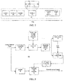
- RF receiver 12 the first element of a typical OFDM receiver 10 is an RF receiver 12.
- RF receiver 12 includes an antenna 14, a low noise amplifier (LNA) 16, an RF bandpass filter 18, an automatic gain control (AGC) circuit 20, an RF mixer 22, an RF carrier frequency local oscillator 24, and an IF bandpass filter 26.
- LNA low noise amplifier
- AGC automatic gain control
- RF receiver 12 couples in the RF OFDM-modulated carrier after it passes through the channel. Then, by mixing it with a receiver carrier of frequency f cr generated by RF local oscillator 24, RF receiver 12 downconverts the RF OFDM-modulated carrier to obtain a received IF OFDM signal. The frequency difference between the receive carrier and the transmit carrier contributes to the carrier frequency offset, delta f c .
- This received IF OFDM signal then feeds into both mixer 28 and mixer 30 to be mixed with an in-phase IF signal and a 90° phase-shifted (quadrature) IF signal, respectively, to produce in-phase and quadrature OFDM signals, respectively.
- the in-phase IF signal that feeds into mixer 28 is produced by an IF local oscillator 32.
- the 90° phase-shifted IF signal that feeds into mixer 30 is derived from the in-phase IF signal of IF local oscillator 32 by passing the in-phase IF signal through a 90° phase shifter 34 before feeding it to mixer 30.
- ADCs 36 and 38 are analog-to-digital converters (ADCs) 36 and 38, respectively, where they are digitized at a sampling rate f ck_r as determined by a clock circuit 40.
- the unfiltered in-phase and quadrature discrete-time OFDM signals from ADCs 36 and 38 then pass through digital low-pass filters 42 and 44, respectively.
- the output of lowpass digital filters 42 and 44 are filtered in-phase and quadrature samples, respectively, of the received OFDM signal.
- These in-phase and quadrature (real-valued and imaginary-valued) samples of the received OFDM signal are then delivered to DSP 46.
- the analog-to-digital conversion is done before the IF mixing process.
- the mixing process involves the use of digital mixers and a digital frequency synthesizer.
- the digital-to-analog conversion is performed after the filtering.
- DSP 46 performs a variety of operations on the in-phase and quadrature samples of the received OFDM signal. These operations may include: a) synchronizing receiver 10 to the timing of the symbols and data frames within the received OFDM signal, b) removing the cyclic prefixes from the received OFDM signal, c) computing the discrete Fourier transform (DFT) or preferably the fast Fourier transform (FFT) of the received OFDM signal in order to recover the sequences of frequency-domain sub-symbols that were used to modulate the sub-carriers during each OFDM symbol interval, d) performing any required channel equalization on the sub-carriers, and e) computing a sequence of frequency-domain sub-symbols, y k , from each symbol of the OFDM signal by demodulating the sub-carriers of the OFDM signal by means of the FFT calculation. DSP 46 then delivers these sequences of sub-symbols to a decoder 48.
- DFT discrete Fourier transform
- Decoder 48 recovers the transmitted data bits from the sequences of frequency-domain sub-symbols that are delivered to it from DSP 46. This recovery is performed by decoding the frequency-domain sub-symbols to obtain a stream of data bits which should ideally match the stream of data bits that were fed into the OFDM transmitter.
- This decoding process can include soft Viterbi decoding and/or Reed-Solomon decoding, for example, to recover the data from the block and/or convolutionally encoded sub-symbols.
- a typical OFDM data transmission system such as one for implementing digital television or a wireless local area network (WLAN)
- data is transmitted in the OFDM signal in groups of symbols known as data frames.
- This concept is shown in FIG. 2 where a data frame 50 includes M consecutive symbols 52a, 52b,...,52M, each of which includes a guard interval, T g , as well as the OFDM symbol interval, Ts. Therefore, each symbol has a total duration of T g +T s seconds.
- data frames can be transmitted continuously, such as in the broadcast of digital TV, or data frames can be transmitted at random times in bursts, such as in the implementation of a WLAN.
- FIG. 3 an exemplary embodiment of the present invention is shown.
- the FIG. 3 arrangement may be employed in the receiver of FIG. 1, as illustrated in FIG. 5.
- the present invention is illustrated as a distinct sampling offset correction loop for clarity, ease of reference, and to facilitate an understanding of the present invention.
- the present invention operates in a receiver that conforms to the proposed ETSI-BRAN HIPERLAN/2 (Europe) and IEEE 802.11a (USA) wireless LAN standards, herein incorporated by reference. However, it is considered within the skill of one skilled in the art to implement the teachings of the present invention in other OFDM systems.
- the above-identified wireless LAN standards propose the use of a training sequence for detection of OFDM transmissions.
- the training sequence (e.g., training sequence A or B) includes a series of short OFDM training symbols (having known amplitudes and phases) that are transmitted over a predetermined number of pilot sub-carriers or bins (e.g., 12 pilot sub-carriers). All the other sub-carriers (e.g., 52 sub-carriers) remain at zero during the transmission of the training sequence.
- Frequency domain and time domain representations of an exemplary training sequence B of HIPERLAN/2 are shown in FIGS. 5 and 6.
- the training sequence has a block of 16 samples that is repeated 4 times per training symbol. This repetitive block or time period is utilized by the present invention, as discussed in further detail below.
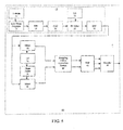
- sampling offset correction system 60 is shown. It should be noted that system 60 may be embodied in software, hardware, or some combination thereof.
- a pair of samplers (e.g., ADCs) 62 and 78 sample a received OFDM signal.
- Sampler 78 samples the OFDM signal at a given sample rate (selected to be near the sampling rate of the transmitter) and passes the sampled OFDM signal through a sampling rate converter 76 for downstream processing (e.g., FFT and the like), as discussed in further detail below.
- Sampler 62 upsamples or oversamples the received OFDM signal by a predetermined factor (e.g., a factor of 2) and passes the upsampled signal to a correlator module 64. Oversampling the received OFDM signal provides a resolution of the OFDM signal that is necessary to derive a meaningful error, as discussed in further detail below.
- sampler 78 and sampler 62 may be interconnected in a number of different ways, as known by one skilled in the art.
- sampler 78 and sampler 62 may be driven by a clock circuit (not shown) that drives both samplers 78 and 62 to oversample the OFDM signal by a factor of 2.
- sampler 62 would pass every sample to a correlator module 64 and sampler 78 would pass every other sample to sampling rate converter 76.
- Correlator module 64 correlates the upsampled signal received from sampler 62 with time-domain samples of the training sequence (e.g., training sequence B of the above-mentioned wireless standards) stored in a local memory 66.
- Each sample in the exemplary training sequence has a value of sqrt(13/6) * [(1 +j) or (-1-j)].
- the memory allocated for storing each sample value will depend on the design of a particular OFDM receiver.
- the stored version of the training sequence is, preferably, a truncated version of the training sequence corresponding to one of the repetitive blocks of samples (e.g., 16 samples) of training sequence B.
- the stored version of the truncated training sequence preferably, corresponds to an oversampled version (e.g., 32 samples) of the repetitive block that is oversampled by the same predetermined factor (e.g., a factor of 2) as used in sampler 62.
- an oversampled version e.g., 32 samples
- the same predetermined factor e.g., a factor of 2
- memory space is efficiently utilized in local memory 66 since the entire training sequence (i.e., 64 samples if the training sequence is not oversampled) is not stored in local memory 66.
- a maximum correlation will occur between the oversampled OFDM signal and the truncated version of the training sequence when the stored training sequence coincides with a training sequence contained in the OFDM signal.
- a peak in the power of the correlation output may be utilized to determine when the received signal coincides with the stored training sequence.
- the output of correlator module 64 is a complex signal since the inputs (i.e., the stored training sequence and the OFDM signal) are complex.
- Power module 68 may compute the power or magnitude of each sample of the correlated signal in one of two ways in accordance with the design of a particular OFDM receiver, First, power module 68 may compute the squared magnitude (i.e., the power) of each complex sample of the correlated signal to generate a real number indicating the power of the correlated signal, Second, power module 68 may obtain the magnitude (as opposed to the squared magnitude) of each complex sample of the correlated signal.
- a peak locator module 70 searches the correlation power sequence output from power module 68 in order to locate the sample in the correlation power sequence having the largest power or magnitude value. Once the largest value is identified, peak locator module 70 outputs the index of the peak location to an error computation module 72. The index is used by error computation module 72 as a reference point.
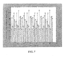
- FIG. 4 shows a main correlation peak 80 and a pair of smaller correlation peaks 82 and 84 on either side of main correlation peak 80. If the OFDM signal was not oversampled by sampler 62, it is likely that only main correlation peak 80 would be present and error computation module 72 would not be able to determine a sampling error 86 derived from the magnitude of correlation peaks in the vicinity of main peak 80, as discussed in further detail below.
- error computation module 72 analyzes correlation samples 82 and 84 on either side of main peak 80. When there is no sampling offset the frequency correlation samples 82 and 84 will have the same magnitude (not shown). However, if there is a sampling offset the correlation samples 82 and 84 will have different magnitudes, as shown in FIG. 4.
- Computation module 72 computes an error value by calculating the difference in magnitude between the correlation samples 82 and 84 on either side of correlation peak 80.
- the difference in magnitude may be positive or negative.
- the magnitude of the difference indicates the degree that the stored training sequence and the received training sequence are out of synch.
- the sign of the difference indicates whether to increase or decrease the sampling frequency.
- the magnitude of the sample to the left of a main correlation peak e.g., main peak index - 1
- the value of the sample to the right of the main correlation peak e.g., main peak index + 1 will produce the error value.
- the error value may be computed as the difference between the right sample and the left sample depending on the requirements of a particular system.
- error computation module 72 outputs the computed error value to a second order loop filter 74 that adjusts the sampling rate such that the sampling error is driven towards zero and the sampling rate of the receiver synchronizes with the sampling rate of the transmitter. More specifically, second order loop filter 74 adjusts the sampling rate of a sampler 78 via a conventional sampling rate converter 76 or, in the alternative, may adjust the sampling rate of sampler 78 and associated upsampler 62.
- sampling offset correction system 60 may be coupled to the outputs of mixers 28 and 30 and to the inputs of DSP 46.
- sampling offset correction system 60 receives the in-phase and quadrature OFDM signals from mixers 28 and 30, digitizes the received signals at a corrected sampling rate that matches the sampling rate of the transmitter, and outputs the digitized signals to DSP 46 for further processing.
- LPF 42 and LPF 44 of FIG. 1 may be coupled to the outputs of sampling offset correction system 60 and to the inputs of DSP 46 for filtering the digitized OFDM signals although such an arrangement is not shown in FIG. 5.
- a method of correcting a sampling offset in an OFDM receiver includes sampling a received OFDM signal, the OFDM signal containing a reference symbol, correlating the sampled OFDM signal with a stored symbol, locating a correlation peak, calculating a difference in magnitude of correlation samples on either side of the correlation peak, and deriving a sampling offset error from the calculated difference.
Landscapes
- Engineering & Computer Science (AREA)
- Computer Networks & Wireless Communication (AREA)
- Signal Processing (AREA)
- Synchronisation In Digital Transmission Systems (AREA)
- Cable Transmission Systems, Equalization Of Radio And Reduction Of Echo (AREA)
- Time-Division Multiplex Systems (AREA)
Applications Claiming Priority (2)
| Application Number | Priority Date | Filing Date | Title |
|---|---|---|---|
| US09/505,159 US6711221B1 (en) | 2000-02-16 | 2000-02-16 | Sampling offset correction in an orthogonal frequency division multiplexing system |
| EP01102093A EP1139624B1 (fr) | 2000-02-16 | 2001-01-31 | Correction d'un décalage en point d'échantillonage dans un système de multiplexage par division en fréquences orthogonaux |
Related Parent Applications (1)
| Application Number | Title | Priority Date | Filing Date |
|---|---|---|---|
| EP01102093A Division EP1139624B1 (fr) | 2000-02-16 | 2001-01-31 | Correction d'un décalage en point d'échantillonage dans un système de multiplexage par division en fréquences orthogonaux |
Publications (1)
| Publication Number | Publication Date |
|---|---|
| EP1892912A1 true EP1892912A1 (fr) | 2008-02-27 |
Family
ID=24009259
Family Applications (2)
| Application Number | Title | Priority Date | Filing Date |
|---|---|---|---|
| EP07121328A Withdrawn EP1892912A1 (fr) | 2000-02-16 | 2001-01-31 | Échantillonnage de correction de décalage dans un système de multiplexage à division de fréquence orthogonale |
| EP01102093A Expired - Lifetime EP1139624B1 (fr) | 2000-02-16 | 2001-01-31 | Correction d'un décalage en point d'échantillonage dans un système de multiplexage par division en fréquences orthogonaux |
Family Applications After (1)
| Application Number | Title | Priority Date | Filing Date |
|---|---|---|---|
| EP01102093A Expired - Lifetime EP1139624B1 (fr) | 2000-02-16 | 2001-01-31 | Correction d'un décalage en point d'échantillonage dans un système de multiplexage par division en fréquences orthogonaux |
Country Status (6)
| Country | Link |
|---|---|
| US (1) | US6711221B1 (fr) |
| EP (2) | EP1892912A1 (fr) |
| JP (1) | JP4920828B2 (fr) |
| KR (1) | KR100756973B1 (fr) |
| CN (2) | CN1309484B (fr) |
| BR (1) | BR0100531A (fr) |
Families Citing this family (42)
| Publication number | Priority date | Publication date | Assignee | Title |
|---|---|---|---|---|
| KR100397353B1 (ko) * | 2001-02-07 | 2003-09-13 | 광주과학기술원 | Ofdm 시스템용 원-탭 등화기뱅크의 신호왜곡 보상방법 |
| US7218691B1 (en) * | 2001-03-05 | 2007-05-15 | Marvell International Ltd. | Method and apparatus for estimation of orthogonal frequency division multiplexing symbol timing and carrier frequency offset |
| US8619922B1 (en) | 2002-02-04 | 2013-12-31 | Marvell International Ltd. | Method and apparatus for acquisition and tracking of orthogonal frequency division multiplexing symbol timing, carrier frequency offset and phase noise |
| US7027530B2 (en) * | 2001-04-11 | 2006-04-11 | Atheros Communications, Inc. | Method and apparatus for maximizing receiver performance utilizing mid-packet gain changes |
| US8498368B1 (en) | 2001-04-11 | 2013-07-30 | Qualcomm Incorporated | Method and system for optimizing gain changes by identifying modulation type and rate |
| US6959050B2 (en) * | 2001-06-15 | 2005-10-25 | Motorola, Inc. | Method and apparatus for synchronizing an OFDM signal |
| AU2002316435B2 (en) | 2001-06-27 | 2008-02-21 | Skky, Llc | Improved media delivery platform |
| US7203255B2 (en) * | 2001-09-24 | 2007-04-10 | Atheros Communications, Inc. | Method and system to implement non-linear filtering and crossover detection for pilot carrier signal phase tracking |
| US7103116B2 (en) * | 2001-09-24 | 2006-09-05 | Atheros Communications, Inc. | Detection of a false detection of a communication packet |
| JP3607238B2 (ja) * | 2001-10-22 | 2005-01-05 | 株式会社東芝 | Ofdm信号受信システム |
| CN100461656C (zh) * | 2001-12-20 | 2009-02-11 | 北京六合万通微电子技术有限公司 | 同步信号检测电路装置及其该装置检测同步信号的检测方法 |
| KR20030090389A (ko) * | 2002-05-23 | 2003-11-28 | 주식회사 신영텔레콤 | 직교주파수분할 다중방식을 사용하는 무선랜 시스템의주파수옵셋 동기획득 방법 |
| US7116731B2 (en) * | 2002-06-03 | 2006-10-03 | Vixs, Inc. | Method and apparatus for adjusting symbol timing and/or symbol positioning of a receive burst of data within a radio receiver |
| US7346131B2 (en) * | 2002-07-10 | 2008-03-18 | Zoran Corporation | System and method for pre-FFT OFDM fine synchronization |
| DE10239810A1 (de) * | 2002-08-29 | 2004-03-11 | Siemens Ag | Verfahren und Sendeeinrichtung zum Übertragen von Daten in einem Mehrträgersystem |
| KR100553544B1 (ko) * | 2002-08-31 | 2006-02-20 | 삼성탈레스 주식회사 | 버스트 직교 주파수분할 다중 전송 시스템에서 주파수 오프셋 추정 및 채널 등화방법 |
| JP4145240B2 (ja) * | 2003-12-26 | 2008-09-03 | 三洋電機株式会社 | ダイバーシチ受信方法および装置 |
| US7426251B1 (en) * | 2004-02-03 | 2008-09-16 | Xilinx, Inc. | High speed transceiver operable to receive lower data rate transmissions |
| US7426252B1 (en) | 2004-02-03 | 2008-09-16 | Xilinx, Inc. | High speed transceiver receiving lower rate data |
| US7472152B1 (en) | 2004-08-02 | 2008-12-30 | The United States Of America As Represented By The Secretary Of The Air Force | Accommodating fourier transformation attenuation between transform term frequencies |
| KR100665004B1 (ko) * | 2004-12-17 | 2007-01-09 | 삼성전기주식회사 | 심벌 동기화 회로를 구비한 수신 장치 |
| US7532645B1 (en) | 2005-01-14 | 2009-05-12 | Xilinx, Inc. | Receiver operable to receive data at a lower data rate |
| KR100605109B1 (ko) * | 2005-01-18 | 2006-07-28 | 삼성전자주식회사 | 직교 주파수분할 다중화 시스템에서 과표본화를 이용한신호대 잡음비 최적화 방법 및 장치 |
| US7720162B2 (en) * | 2005-03-10 | 2010-05-18 | Qualcomm Incorporated | Partial FFT processing and demodulation for a system with multiple subcarriers |
| US7756005B2 (en) * | 2005-03-11 | 2010-07-13 | Qualcomm Incorporated | Coarse timing/frame acquisition of OFDM system using time division multiplexed pilot symbol |
| KR100699490B1 (ko) * | 2005-08-22 | 2007-03-26 | 삼성전자주식회사 | 샘플링 주파수 오프셋 추정방법 및 이 방법이 적용되는ofdm 시스템 |
| US7675846B2 (en) * | 2006-06-23 | 2010-03-09 | Telefonaktiebolaget L M Ericsson (Publ) | Method and system for using the synchronization channel to obtain measurements in a cellular communications system |
| JP2009010754A (ja) | 2007-06-28 | 2009-01-15 | Naoki Suehiro | 並列サンプリング装置、並列サンプリング方法、受信装置及び受信方法 |
| IL203785A (en) | 2007-09-12 | 2014-07-31 | Qualcomm Inc | Devices to increase capacitance and methods for wireless communication |
| EP2445156A3 (fr) * | 2007-09-14 | 2012-10-24 | France Telecom | Synchronisation trame dans un systeme de communication ofdm |
| US8817934B2 (en) * | 2010-07-28 | 2014-08-26 | Qualcomm Incorporated | System and method for synchronization tracking in an in-band modem |
| CN103166898B (zh) * | 2013-03-29 | 2015-11-18 | 东南大学 | 一种OFDM系统中基于周期Zadoff-Chu序列精确时延跟踪方法 |
| GB2532233A (en) * | 2014-11-12 | 2016-05-18 | Sony Corp | Transmitter and receiver and methods of transmitting and receiving |
| GB2539018B (en) * | 2015-06-03 | 2019-11-06 | Imagination Tech Ltd | Sampling frequency offset calculation |
| US9813267B1 (en) | 2016-05-27 | 2017-11-07 | Nxp Usa, Inc. | Communicaton unit, circuit for quadrature sampling error estimation and compensation and method therefor |
| WO2018141932A1 (fr) * | 2017-02-06 | 2018-08-09 | Telefonaktiebolaget Lm Ericsson (Publ) | Systèmes et procédés pour réduire au minimum un impact de performance à partir de distorsions de signal connues |
| CN108737318B (zh) * | 2018-07-19 | 2020-10-13 | 中国人民解放军战略支援部队信息工程大学 | 基于信号结构特性的ofdm信号识别方法及系统 |
| WO2020184965A1 (fr) * | 2019-03-13 | 2020-09-17 | 엘지전자 주식회사 | Procédé de commande d'une pluralité d'unités distantes d'antenne dans un système de communication sans fil prenant en charge une liaison latérale, et dispositif associé |
| CN112583571B (zh) * | 2019-09-30 | 2024-07-23 | 深圳市中兴微电子技术有限公司 | 一种信号的采样方法及装置 |
| CN114374500B (zh) * | 2020-10-15 | 2024-09-03 | 瑞昱半导体股份有限公司 | 能够准确估计讯号时偏的接收机电路及方法 |
| EP4047893A1 (fr) * | 2021-02-23 | 2022-08-24 | Nokia Solutions and Networks Oy | Égaliseur et unité de formation d'égaliseur de compensation de distorsion dépendant de données |
| CN119788481B (zh) * | 2025-03-10 | 2025-05-23 | 北京历正科技有限责任公司 | 一种未知ofdm信号帧结构参数的识别方法和系统 |
Citations (4)
| Publication number | Priority date | Publication date | Assignee | Title |
|---|---|---|---|---|
| US4598413A (en) * | 1983-09-17 | 1986-07-01 | International Standard Electric Corporation | Circuit arrangement for frame and phase synchronization of a local sampling clock |
| GB2206267A (en) * | 1987-06-24 | 1988-12-29 | Plessey Co Plc | Correlator for synchronisation detection |
| DE4330672A1 (de) * | 1993-09-10 | 1995-03-16 | Thomson Brandt Gmbh | Verfahren zur ]bertragung von digitalisierten Fernseh- und/oder Tonrundfunksignalen |
| WO1999057806A1 (fr) * | 1998-04-30 | 1999-11-11 | Nokia Networks Oy | Procede de linearisation pour amplificateur, et systeme amplificateur |
Family Cites Families (21)
| Publication number | Priority date | Publication date | Assignee | Title |
|---|---|---|---|---|
| SE9302453L (sv) | 1993-07-20 | 1994-10-17 | Telia Ab | Förfarande och anordning för synkronisering i digitalt transmissionssystem av typen OFDM |
| US5444697A (en) | 1993-08-11 | 1995-08-22 | The University Of British Columbia | Method and apparatus for frame synchronization in mobile OFDM data communication |
| JP3041175B2 (ja) | 1993-11-12 | 2000-05-15 | 株式会社東芝 | Ofdm同期復調回路 |
| EP0684708B1 (fr) | 1993-12-15 | 2005-10-26 | Ntt Mobile Communications Network Inc. | Egaliseur a adaptation automatique |
| US5774450A (en) | 1995-01-10 | 1998-06-30 | Matsushita Electric Industrial Co., Ltd. | Method of transmitting orthogonal frequency division multiplexing signal and receiver thereof |
| JP3130752B2 (ja) | 1995-02-24 | 2001-01-31 | 株式会社東芝 | Ofdm伝送受信方式及び送受信装置 |
| SE514986C2 (sv) | 1995-03-01 | 2001-05-28 | Telia Ab | Metod och anordning för synkronisering vid OFDM-system |
| JPH08265292A (ja) * | 1995-03-22 | 1996-10-11 | Toshiba Corp | Ofdm受信装置 |
| JP3145003B2 (ja) | 1995-03-23 | 2001-03-12 | 株式会社東芝 | 直交周波数分割多重伝送方式とその送信装置および受信装置 |
| JP3079950B2 (ja) | 1995-06-20 | 2000-08-21 | 松下電器産業株式会社 | 直交周波数分割多重変調信号の受信装置及び伝送方法 |
| US5790516A (en) | 1995-07-14 | 1998-08-04 | Telefonaktiebolaget Lm Ericsson | Pulse shaping for data transmission in an orthogonal frequency division multiplexed system |
| JP2802255B2 (ja) * | 1995-09-06 | 1998-09-24 | 株式会社次世代デジタルテレビジョン放送システム研究所 | 直交周波数分割多重伝送方式及びそれを用いる送信装置と受信装置 |
| JPH09130362A (ja) | 1995-10-30 | 1997-05-16 | Sony Corp | 受信装置および受信方法 |
| US5732113A (en) | 1996-06-20 | 1998-03-24 | Stanford University | Timing and frequency synchronization of OFDM signals |
| JP3726857B2 (ja) | 1997-05-02 | 2005-12-14 | ソニー株式会社 | 受信装置および受信方法 |
| KR100265735B1 (ko) | 1997-11-25 | 2000-09-15 | 윤종용 | Fft윈도우위치복원과샘플링클럭제어가연동되는ofdm수신장치및그방법 |
| WO1999053665A1 (fr) * | 1998-04-14 | 1999-10-21 | Fraunhnofer-Gesellschaft Zur Förderung Der Angewand Ten Forschung E.V. | Synchronisation approximative de frequences pour des systemes a porteuses multiples |
| US6111919A (en) * | 1999-01-20 | 2000-08-29 | Intellon Corporation | Synchronization of OFDM signals |
| US6074086A (en) * | 1999-04-26 | 2000-06-13 | Intellon Corporation | Synchronization of OFDM signals with improved windowing |
| US6546056B1 (en) * | 1999-05-28 | 2003-04-08 | 3Com Corporation | Timing recovery in a multi-tone modem |
| US6459745B1 (en) * | 1999-09-23 | 2002-10-01 | The United States Of America As Represented By The Secretary Of The Navy | Frequency/timing recovery circuit for orthogonal frequency division multiplexed signals |
-
2000
- 2000-02-16 US US09/505,159 patent/US6711221B1/en not_active Expired - Lifetime
-
2001
- 2001-01-31 EP EP07121328A patent/EP1892912A1/fr not_active Withdrawn
- 2001-01-31 EP EP01102093A patent/EP1139624B1/fr not_active Expired - Lifetime
- 2001-02-14 KR KR1020010007315A patent/KR100756973B1/ko not_active Expired - Fee Related
- 2001-02-14 BR BR0100531-6A patent/BR0100531A/pt active Search and Examination
- 2001-02-16 JP JP2001040282A patent/JP4920828B2/ja not_active Expired - Fee Related
- 2001-02-16 CN CN011045612A patent/CN1309484B/zh not_active Expired - Fee Related
- 2001-02-16 CN CNA2007100965692A patent/CN101039302A/zh active Pending
Patent Citations (4)
| Publication number | Priority date | Publication date | Assignee | Title |
|---|---|---|---|---|
| US4598413A (en) * | 1983-09-17 | 1986-07-01 | International Standard Electric Corporation | Circuit arrangement for frame and phase synchronization of a local sampling clock |
| GB2206267A (en) * | 1987-06-24 | 1988-12-29 | Plessey Co Plc | Correlator for synchronisation detection |
| DE4330672A1 (de) * | 1993-09-10 | 1995-03-16 | Thomson Brandt Gmbh | Verfahren zur ]bertragung von digitalisierten Fernseh- und/oder Tonrundfunksignalen |
| WO1999057806A1 (fr) * | 1998-04-30 | 1999-11-11 | Nokia Networks Oy | Procede de linearisation pour amplificateur, et systeme amplificateur |
Non-Patent Citations (1)
| Title |
|---|
| MUELLER-WEINFURTNER S H: "ON THE OPTIMALITY OF METRICS FOR COARSE FRAME SYNCHRONIZATION IN OFDM: A COMPARISON", IEEE INTERNATIONAL SYMPOSIUM ON PERSONAL, INDOOR AND MOBILE RADIO COMMUNICATIONS, XX, XX, vol. 2, 8 September 1998 (1998-09-08), pages 533 - 537, XP000858591 * |
Also Published As
| Publication number | Publication date |
|---|---|
| US6711221B1 (en) | 2004-03-23 |
| EP1139624A2 (fr) | 2001-10-04 |
| KR20010082635A (ko) | 2001-08-30 |
| EP1139624B1 (fr) | 2012-07-25 |
| JP2001268041A (ja) | 2001-09-28 |
| JP4920828B2 (ja) | 2012-04-18 |
| BR0100531A (pt) | 2001-10-02 |
| CN101039302A (zh) | 2007-09-19 |
| CN1309484A (zh) | 2001-08-22 |
| EP1139624A3 (fr) | 2004-06-16 |
| KR100756973B1 (ko) | 2007-09-07 |
| CN1309484B (zh) | 2011-01-19 |
Similar Documents
| Publication | Publication Date | Title |
|---|---|---|
| US6711221B1 (en) | Sampling offset correction in an orthogonal frequency division multiplexing system | |
| EP1126673B1 (fr) | Correction d'un décalage en fréquence dans un récepteur multiporteuse | |
| EP1245104B1 (fr) | Correction d'un decalage de frequence d'echantillonnage dans un systeme de multiplexage par division de frequence orthogonale | |
| EP0929172B1 (fr) | Système de modulation multiporteuse, à débits de symboles variables | |
| EP0971515B1 (fr) | Structure de symbole de référence pour la synchronisation de fréquence, de symboles et de trames dans des système multiporteurs | |
| US6546055B1 (en) | Carrier offset determination for RF signals having a cyclic prefix | |
| US7039000B2 (en) | Timing synchronization for OFDM-based wireless networks | |
| EP1108295B1 (fr) | Procédé de formation d'une séquence d'apprentissage | |
| US6961393B1 (en) | In-band-on-channel (IBOC) system and methods of operation using orthogonal frequency division multiplexing (OFDM) with timing and frequency offset correction | |
| US8774330B2 (en) | Coarse timing acquisition | |
| EP1755300B1 (fr) | Synchronisation dans des récepteurs multiporteuses | |
| US9008195B2 (en) | Detection of a packet type in a communications system | |
| US7065171B1 (en) | Method for synchronization of received signals | |
| MXPA01001706A (en) | Sampling offset correction in an orthogonal frequency division multiplexing system | |
| KR100697526B1 (ko) | 디지털 방송 수신기의 트래킹 장치 | |
| KR100236040B1 (ko) | 직교분할대역 시스템의 간략시간 획득회로 | |
| MXPA01001707A (en) | Frequency offset correction in a multicarrier receiver | |
| KR20080000337A (ko) | 방송 신호 수신 장치 및 방송 신호 수신 방법 |
Legal Events
| Date | Code | Title | Description |
|---|---|---|---|
| PUAI | Public reference made under article 153(3) epc to a published international application that has entered the european phase |
Free format text: ORIGINAL CODE: 0009012 |
|
| AC | Divisional application: reference to earlier application |
Ref document number: 1139624 Country of ref document: EP Kind code of ref document: P |
|
| AK | Designated contracting states |
Kind code of ref document: A1 Designated state(s): DE FR GB IT |
|
| 17P | Request for examination filed |
Effective date: 20080827 |
|
| AKX | Designation fees paid |
Designated state(s): DE FR GB |
|
| RAP1 | Party data changed (applicant data changed or rights of an application transferred) |
Owner name: THOMSON LICENSING SA |
|
| 17Q | First examination report despatched |
Effective date: 20131118 |
|
| GRAP | Despatch of communication of intention to grant a patent |
Free format text: ORIGINAL CODE: EPIDOSNIGR1 |
|
| INTG | Intention to grant announced |
Effective date: 20170324 |
|
| RAP1 | Party data changed (applicant data changed or rights of an application transferred) |
Owner name: THOMSON LICENSING DTV |
|
| STAA | Information on the status of an ep patent application or granted ep patent |
Free format text: STATUS: THE APPLICATION IS DEEMED TO BE WITHDRAWN |
|
| 18D | Application deemed to be withdrawn |
Effective date: 20170804 |