EP1893111B1 - Chirurgische biegezange und biegezangensystem - Google Patents
Chirurgische biegezange und biegezangensystem Download PDFInfo
- Publication number
- EP1893111B1 EP1893111B1 EP06762141.7A EP06762141A EP1893111B1 EP 1893111 B1 EP1893111 B1 EP 1893111B1 EP 06762141 A EP06762141 A EP 06762141A EP 1893111 B1 EP1893111 B1 EP 1893111B1
- Authority
- EP
- European Patent Office
- Prior art keywords
- bending
- punch
- branches
- bending punch
- forceps
- Prior art date
- Legal status (The legal status is an assumption and is not a legal conclusion. Google has not performed a legal analysis and makes no representation as to the accuracy of the status listed.)
- Not-in-force
Links
- 238000005452 bending Methods 0.000 title claims description 154
- 210000000988 bone and bone Anatomy 0.000 claims description 52
- 230000007246 mechanism Effects 0.000 claims description 7
- 230000000295 complement effect Effects 0.000 claims description 5
- 230000000087 stabilizing effect Effects 0.000 claims description 5
- 241001481828 Glyptocephalus cynoglossus Species 0.000 claims 1
- 230000005540 biological transmission Effects 0.000 description 10
- 238000013459 approach Methods 0.000 description 3
- 238000000034 method Methods 0.000 description 3
- 238000013001 point bending Methods 0.000 description 3
- 238000004080 punching Methods 0.000 description 3
- 238000012986 modification Methods 0.000 description 2
- 230000004048 modification Effects 0.000 description 2
- 238000004873 anchoring Methods 0.000 description 1
- 238000006243 chemical reaction Methods 0.000 description 1
- 238000013461 design Methods 0.000 description 1
- 230000000368 destabilizing effect Effects 0.000 description 1
- 238000011161 development Methods 0.000 description 1
- 239000007943 implant Substances 0.000 description 1
- 238000001356 surgical procedure Methods 0.000 description 1
- 238000013519 translation Methods 0.000 description 1
Images


Classifications
-
- A—HUMAN NECESSITIES
- A61—MEDICAL OR VETERINARY SCIENCE; HYGIENE
- A61B—DIAGNOSIS; SURGERY; IDENTIFICATION
- A61B17/00—Surgical instruments, devices or methods
- A61B17/56—Surgical instruments or methods for treatment of bones or joints; Devices specially adapted therefor
- A61B17/58—Surgical instruments or methods for treatment of bones or joints; Devices specially adapted therefor for osteosynthesis, e.g. bone plates, screws or setting implements
- A61B17/88—Osteosynthesis instruments; Methods or means for implanting or extracting internal or external fixation devices
- A61B17/8863—Apparatus for shaping or cutting osteosynthesis equipment by medical personnel
Definitions
- the invention relates to a bending forceps for surgical elements, as used for example for bending bone plates for the craniomaxillofacialen area.
- the invention further relates to a bending pliers system comprising the bending pliers.
- anatomical conditions can be determined for example by the curvature of a bone or the course of a fracture.
- surgeon has a wide range of instruments at his disposal. These instruments include, for example, cutting tongs, bending tongs, cupboards and similar aids.
- the bending pliers have two sectors pivotable about a common axis of rotation. In the area of the common axis of rotation, a bending punch is provided.
- the bending punch two counter bearings are assigned, which are formed at free ends of the industries.
- the bending punch Upon actuation of the branches, the bending punch remains stationary and the two counter bearings execute movements on elliptical paths around the bending punch. As a result of these movements, a rod disposed between the bending punch and the abutments is bent around the bending punch.
- the punch In order to bend rods of different diameters (or to achieve different bending radii), the punch has a sectionally different outer contour. By turning the bending punch around the axis of rotation of the branches, a desired contour section can be selected, by means of which the bending punch is to interact with the rod to be bent.
- the US 5,490,409 discloses another three-point bending pliers with a rotatable, eccentrically mounted bending punch.
- a mechanism with two Provided over a joint coupled arms.
- a guide pin is arranged, which performs a linear movement upon actuation of the bending pliers.
- the guide pin slides within a channel formed on the back side of the bending punch in order to fix the bending punch in a fixed angle.
- a linear bone plate can be bent both in a preferred plane of the bone plate and from the preferred plane out.
- the bending of the bone plate in the preferred plane by means of a three-point mechanism.
- the three-point mechanism comprises two abutments provided in the head area of a first sector and a bending punch, which is formed on a jaw section pivotally mounted in the head area of the first branch.
- the mouth portion is coupled via a joint with a second branch.
- a connecting web between the first and the second branch is guided with its first end within a slot formed in the first sector and hinged with its second end to the second branch.
- the bending pliers comprise a bending punch, which is pivotable with respect to two abutments.
- a sufficient deflectability of the punch is given, so that bone plates can be bent with different geometric dimensions.
- the pivoting movement of the punch can have a destabilizing effect on the position of the bone plate to be bent.
- a pliers which serves both for punching as well as for bending curtain rails.
- the pliers have at their cheek ends punching tools, with the help of triangular cutouts are punched out.
- it has an abutment roller, which means one with the Both pliers handles connected toggle lever can be operated.
- As a counterhold to the abutment roller serve two Auflagernocken, which are mounted below the punching tool on the shoulders of the gripping arms of the pliers.
- the abutment roller and the bearing cams each have at their root a smaller cross section than at their free end. This creates a special profile for receiving the T-shaped curtain rail.
- the invention has for its object to provide a bending forceps for surgical elements such as bone plates, which has a wide range of applications and allows precise bending.
- Another object of the present invention is to provide a bending pliers system comprising the bending pliers.
- a surgical tool bending pliers comprises two relatively pivotable branches coupled together with at least two first abutments for the surgical element to be bent (eg, rigid or hinged), a first punch for cooperation with the surgical element in an area between the two first abutments and an actuating device for the first bending punch, which converts an actuating movement of the branches in a linear movement of the first punch in the direction of the surgical element, wherein the first abutment move apart during the actuation movement of the branches in each case an elliptical path.
- the actuating device for the first bending punch may be designed such that the first bending punch is movable by the actuating device along a (imaginary) straight line.
- guiding means can be provided which stabilize the linear movement of the first bending punch.
- the actuating device comprises a gearbox for converting the pivoting movement of the sectors into the desired linear movement of the bending punch.
- the transmission may have a translation such that the pivotal movement of the branches in a comparatively wide axial offset Ellipsenscher transmission be formed.
- Exemplary elliptical link transmissions are described in chapters 3.4.5.7.1. and 3.4.5.7.2. of the textbook of S. Hildebrand, Precision Mechanical Components, Karl Hanser Verlag, Münch en described.
- the described elliptical link transmissions, and modifications thereof, are suitable for converting an actuating movement of the branches into a linear bending punch movement.
- the transmission can be articulatedly coupled to each of the two branches as well as to the bending punch.
- the actuating device (that is to say, for example, the elliptical linkage transmission) comprises at least one first lever, which is articulatedly coupled to a first of the two branches and to the first bending punch.
- the actuating device may further comprise a second lever which coupled with the second industry and also with the first bending punch articulated.
- the first and the second lever can be coupled together and with the first bending punch.
- the common joint is formed according to a first variant directly in the region of the first punch.
- the first bending punch is provided at a distance from the common hinge.
- the bending pliers may comprise an extension web with two opposite ends. At a first end of the extension web, the first bending punch is expediently arranged, while a second end of the extension web can be coupled in an articulated manner to the first and the second lever.
- the first bending punch may be formed integrally with the extension web.
- the two first abutment can be fixed relative to each other stationary or have a variable depending on the operating state of the bending pliers distance from each other. It can be thought of providing both counter bearings to the same industry. However, it would also be conceivable to design one of the two first abutments in each of the two sectors.
- the first abutments or the first flexure or all of these components may be contoured to cooperate with a complementary contour of the surgical element. Such a measure has a stabilizing effect on the position of the surgical element and therefore facilitates the bending process.
- a separate axis of rotation is provided for each of the two pivotable branches.
- the axes of rotation of the two sectors are spaced apart in this case.
- both sectors are pivotable about a common axis of rotation.
- the branches with a common axis of rotation each have a second abutment for the surgical element.
- a second, stationary during an actuation movement of the branches fixed punch is provided which is provided for cooperation with the surgical element in a region between the two second abutments.
- a nominal distance between the second bending punch and the second counter bearings is adjustable.
- the second punch can be eccentrically rotatable and / or have different contour sections.
- the first and second abutments and the first and second bending dies may be provided at different positions of the same bending pliers.
- the first abutment and the first bending punch are expediently formed on a first side of the branches, and the second abutment and the second bending punch are formed on a second side of the branches opposite the first side.
- a bending forceps system for surgical elements such as bone plates.
- the bending forceps system includes, in addition to the bending forceps, the surgical element to be bent.
- the surgical element for example a linear bone plate, may have a preferential plane.
- the bending pliers may be configured to bend the surgical element both in the preferred plane and out of the preferential plane.
- the bending in the preferred plane is expediently carried out by means of the first abutment and the first bending punch, while for bending out of the preferred plane out the second abutment and the second bending punch can be used.
- suitable abutment surfaces for the surgical element to be bent are formed in the region of the abutment and bending punch in order to be able to position the preferred plane with respect to the abutment and bending punch in accordance with the requirements.
- a multifunctional surgical bending forceps for bone plates is only to be understood as exemplary, since the bending pliers are also suitable for bending other surgical elements, such as rods or wires, which have no preferential plane.
- the embodiment of a multifunctional bending pliers with two separate mechanisms has the object, on the one hand for bending the bone plate in a preferred plane and on the other hand for bending out of the preferred plane out. It goes without saying that one of the two mechanisms could also be omitted or changed.
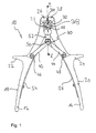
- Fig. 1 shows a front view of a generally designated by the reference numeral 10 bending pliers according to a preferred embodiment with two branches 12, 14.
- the two branches 12, 14 are in the exemplary embodiment about a common axis of rotation, in Fig. 1 is defined by a pivot bearing 16, pivotally.
- lower ends of the two branches 12, 14 are designed as handles 18, 20.
- the handles 18, 20 each have a textured surface and open in the direction of the pivot bearing 16 in each case an outwardly extending projection 22, 24.
- the two projections 22, 24 facilitate the operation of the bending pliers 10 and prevent the same as the structured surfaces a slipping of a surgeon's hand towards the bone plate to be bent. The risk of slipping would be especially when higher actuation forces are required for thicker bone plates.
- Each of the two branches 12, 14 opens at its end facing away from the respective handle 18, 20 end in a roller-like abutment 26, 28.
- the abutment 26, 28 are rigidly coupled to the branches 12, 14 (and the handles 18, 20) .
- the counter-bearings 26, 28 extend into Fig. 1 out of the plane of the drawing (cf. Fig. 3 ) and each have a coarse teardrop-shaped outer contour.
- the distance between the two abutments 26, 28 from the common axis of rotation of the two branches 12, 14 is significantly shorter than the distance between the two handles 20, 22 from the axis of rotation. The resulting leverage reduces the force required to bend the bone plate 30.
- the outer contour of the abutment 26, 28 is to the contour of the bone plate to be bent (in Fig. 1 only shown schematically and designated by the reference numeral 30) adapted and substantially complementary thereto.
- the contouring has a stabilizing effect on the bone plate 30 during a bending process and therefore simplifies the handling of the bending pliers 10.
- a bending punch 32 is provided in an area between the two abutments 26, 28 (and in the FIGS. 1 and 3 below these abutments 26, 28).
- the bending punch 32 is covered by a linear guide 33 for the punch 32.
- the linear guide 33 is in the plan according to Fig. 1 Contoured complementary to the bone plate 30. This contouring facilitates the reception of the bone plate 30 to be bent.
- the bending punch 32 has, like the abutments 26, 28, an approximately teardrop-shaped outer contour with a bulge pointing in the direction of the bone plate 30 (not visible in the figures). It is thus also contoured substantially complementary to the bone plate 30 and adapted to cooperate with the bone plate 30 in a slimmed region 30A (formed between two through-holes 30B for fasteners such as bone screws).
- an actuating device 40 is provided for the bending punch 32.
- the actuating device 40 converts an actuating movement of the two branches 12, 14 into a linear movement of the bending punch 32 in the direction of the two counter bearings 26, 28 and thus also in the direction of the bone plate 30.
- the actuating device 40 is designed in the manner of an elliptical linkage transmission, but in contrast to "conventional" elliptical linkage transmissions (see the aforementioned textbook by S. Hildebrand), no fixed anchoring point is provided in the exemplary embodiment. Rather, in the present case, the elliptical link transmission is coupled to each of the two movable branches 12, 14 and the bending punch 32 to be driven.
- the one lever 42 is coupled via an articulation 46 to one branch 12 and the other lever 44 via another joint 48 to the other branch 14.
- the two levers 42, 44 coupled by means of a common joint 50 with each other and with the punch 32.
- the two levers 42, 44 are connected to the common joint 50 with an extension web 52 carrying the bending punch 32.
- the punch 32 is formed integrally with the extension web 52.
- the extension web 52 slides along the linear guide 33, so that the linear guide 32 has a stabilizing effect on the movement of the extension web 52 and thus also stabilizing on the movement of the bending punch 32.
- Fig. 1 shows the initial or normal position of the bending pliers 10. In this position, the two handles 18, 20 of in Fig. 1 only partially shown leaf springs 54, 56 held spaced from each other. Upon actuation of the bending pliers 10, consequently, the bias of the leaf springs 54, 56 to overcome.
- FIG. 1 shown front of the bending pliers 10 with the punch 32 and the two abutments 26, 28 is intended to bend the bone plate 30 in its preferred plane.
- the bone plate 30 as in Fig. 1 indicated on the front surface of the bending pliers 10 applied flat, in a space between the punch 32 on the one hand and the two abutments 26, 28 on the other.
- the bone plate 30 When the bone plate 30 is applied, it is positioned by the surgeon in such a way that the slimmer region 30A is placed centrally with respect to the bulge of the bending punch 32. In this case, the bulbous portions of the bone plate 30 are automatically positioned correctly with respect to the contoured abutment 26, 28. Subsequently, upon actuation of the branches 12, 14, overcoming the bias of the leaf springs 54, 56, a movement of the branches 12, 14 toward each other.
- the actuating movement of the branches 12, 14 is converted by the actuating device 40 into a linear movement of the bending punch 32 in the direction of the bone plate 30.
- This conversion is due to the fact that the two levers 42, 44 approach each other.
- the common joint 50 of the two levers 42, 44 and thus also coupled to this joint 50 extension web 52 for the punch 32 in the direction of the bone plate 30 moves.
- the resulting movement of the punch 32 is along the dashed line indicated by the arrows A.
- the punch 32 is guided along a straight line substantially perpendicular to the bone plate 30 and not on an elliptical orbit. This allows for increased precision in bending, since no laterally directed (shear) forces occur. It is also advantageous that a comparatively small actuating movement of the branches 12, 14 can be converted into a relatively large linear offset of the bending punch 32. This has the consequence that the nominal distance between the two counter-bearings 26, 28 and the punch 32 can be kept comparatively large. Accordingly, different width bone plates 30 can be positioned and bent between the punch 32 and the abutments 26, 28.
- the bending process is supported by the movement of the abutments 26, 28 (each on an elliptical path).
- This support is essentially that the bone plate 30 is due to the movement of the abutment 26, 28 so to speak bent around the punch 32 around.
- Fig. 2 shows a plan view of the back of the bending pliers 10 with a device 60 for bending the only schematically illustrated bone plate 30 from the preferred plane out.
- the device 60 comprises two roller-like abutments 62, 64 and a bending punch 66.
- Each of the two abutments 62, 64 is formed on an end of the branches 12, 14 facing away from the respective handle 18, 20.
- the counter bearings 62, 64 extend into Fig. 2 out of the plane of the drawing (cf. Fig. 3 ) and each have a circular outer contour.
- the distance between the two abutments 62, 64 from the common axis of rotation of the two branches 12, 14 is significantly shorter than the distance between the two handles 20, 22 from the axis of rotation. The resulting leverage reduces the force required to bend the bone plate 30.
- the bending punch 66 is rotatable with respect to the common pivot bearing 16 of the two branches 12, 14. As Fig. 2 can be removed, has the punch 66 is an elliptical basic shape and is mounted eccentrically with respect to the axis of rotation 16. The eccentric mounting of the punch 66 is also apparent from the sectional view Fig. 3 ,
- the bending punch 66 can be positioned with respect to the pivot bearing 16 in two different locking positions.
- first detent position is a first distance between the bone plate 30 facing the end of the punch 66 and the bone plate 30 facing ends of the abutment 62, 64 set.
- the bending punch 66 can from the in FIGS. 2 and 3 shown detent position are brought into a rotated by 180 ° with respect to the axis of rotation of the branches 12, 14 second detent position.
- a second distance between the bending punch 66 and the two abutments 62, 64 is set due to the eccentric mounting of the punch 66, which is greater than the above-mentioned first distance.
- the second detent position is therefore particularly suitable for bending thicker bone plates.
- Fig. 2 shows how Fig. 1 the initial state of the bending pliers 10.
- the punch 66 is positioned such that the end face of the flat bone plate 30 on the surface of the bending pliers 10 (more precisely on the surfaces of the branches 12, 14).
- the bone plate 30 is therefore positioned upright. Since the distance between the abutments 62, 64 and the punch 66 in the in Fig. 1 shown initial position only slightly larger than the thickness of the bone plate 30, the position of the bone plate 30 is stabilized by the abutments 62, 64 and the punch 66.
- the surgeon actuates the branches 12, 14 by overcoming the bias of the leaf springs 54, 56 towards each other.
- this actuation movement of the branches 12, 14 of the punch 66 remains stationary.
- the counter-bearings 62, 64 move on elliptical paths around the punch 66 around. From this movement of the counter-bearings 62, 64, the bone plate 30 positioned between the counter-bearings 62, 64 and the bending punch 66 is detected and thus bent around the bending punch 66. Since the preferential plane of the bone plate 30 is perpendicular to the axis of rotation of the two branches 12, 14, the bone plate 30 is bent out of its preferred plane.
Landscapes
- Health & Medical Sciences (AREA)
- Life Sciences & Earth Sciences (AREA)
- Orthopedic Medicine & Surgery (AREA)
- Surgery (AREA)
- Biomedical Technology (AREA)
- Engineering & Computer Science (AREA)
- Nuclear Medicine, Radiotherapy & Molecular Imaging (AREA)
- Heart & Thoracic Surgery (AREA)
- Medical Informatics (AREA)
- Molecular Biology (AREA)
- Animal Behavior & Ethology (AREA)
- General Health & Medical Sciences (AREA)
- Public Health (AREA)
- Veterinary Medicine (AREA)
- Surgical Instruments (AREA)
Description
- Die Erfindung betrifft eine Biegezange für chirurgische Elemente, wie sie beispielsweise zum Biegen von Knochenplatten für den craniomaxillofacialen Bereich verwendet wird. Die Erfindung betrifft ferner ein die Biegezange umfassendes Biegezangensystem.
- Im Vorfeld oder während eines chirurgischen Eingriffs ist es oftmals erforderlich, Implantate und andere chirurgische Elemente an anatomische Gegebenheiten anzupassen. Die anatomischen Gegebenheiten können beispielsweise durch die Krümmung eines Knochens oder den Verlauf einer Fraktur bestimmt sein. Zum Anpassen von chirurgischen Elementen an anatomische Gegebenheiten steht dem Chirurgen ein breites Instrumentarium zur Verfügung. Zu diesem Instrumentarium zählen beispielsweise Schneidzangen, Biegezangen, Schränkeisen und ähnliche Hilfsmittel.
- Aus der
US 4,474,046 ist eine Dreipunkt-Biegezange für chirurgische Stäbe bekannt. Die Biegezange besitzt zwei um eine gemeinsame Drehachse schwenkbare Branchen. Im Bereich der gemeinsamen Drehachse ist ein Biegestempel vorgesehen. Dem Biegestempel sind zwei Gegenlager zugeordnet, die an freien Enden der Branchen ausgebildet sind. Bei einer Betätigung der Branchen bleibt der Biegestempel ortsfest und die beiden Gegenlager führen Bewegungen auf elliptischen Bahnen um den Biegestempel herum aus. Als Folge dieser Bewegungen wird eine zwischen dem Biegestempel und den Gegenlagern angeordnete Stange um den Biegestempel herum gebogen. Um Stangen unterschiedlichen Durchmessers biegen zu können (oder zum Erzielen unterschiedlicher Biegeradien), besitzt der Biegestempel eine abschnittsweise unterschiedliche Außenkontur. Durch Drehen des Biegestempels um die Drehachse der Branchen lässt sich ein gewünschter Konturabschnitt auswählen, mittels dessen der Biegestempel mit der zu biegenden Stange zusammenwirken soll. - Die
US 5,490,409 offenbart eine weitere Dreipunkt-Biegezange mit einem drehbaren, exzentrisch gelagerten Biegestempel. Um den drehbaren Biegestempel in einer gewünschten Winkelstellung sicher arretieren zu können, ist ein Mechanismus mit zwei über ein Gelenk miteinander gekoppelten Armen vorgesehen. Im Bereich des Gelenks ist ein Führungsstift angeordnet, der bei einer Betätigung der Biegezange eine lineare Bewegung ausführt. Dabei gleitet der Führungsstift innerhalb eines auf der Rückseite des Biegestempels ausgebildeten Kanals, um den Biegestempel winkelfest zu fixieren. - Aus der
US 5,651,283 ist eine multifunktionale Biegezange für lineare Knochenplatten bekannt. Mittels der Biegezange kann eine lineare Knochenplatte sowohl in einer Vorzugsebene der Knochenplatte als auch aus der Vorzugsebene heraus gebogen werden. Das Biegen der Knochenplatte in der Vorzugsebene erfolgt mittels einer Dreipunkt-Mechanik. Die Dreipunkt-Mechanik umfasst zwei im Kopfbereich einer ersten Branche vorgesehene Gegenlager sowie einen Biegestempel, der an einem im Kopfbereich der ersten Branche schwenkbar gelagerten Maulabschnitt ausgebildet ist. Der Maulabschnitt ist über ein Gelenk mit einer zweiten Branche gekoppelt. Ein Verbindungssteg zwischen der ersten und der zweiten Branche ist mit seinem ersten Ende innerhalb eines in der ersten Branche ausgebildeten Schlitzes geführt und mit seinem zweiten Ende an der zweiten Branche angelenkt. - Es hat sich herausgestellt, dass der aus der
US 5,651,283 bekannte Ansatz, den Biegestempel an einem schwenkbaren Maulabschnitt vorzusehen, nachteilhaft ist. Ein Nachteil besteht beispielsweise darin, dass der Biegestempel nur begrenzt auslenkbar ist. Aufgrund dieser begrenzten Auslenkbarkeit ist der Anwendungsbereich der Biegezange im Wesentlichen auf Knochenplatten mit eng begrenzten geometrischen Dimensionen bestimmt. - Aus der
DE 103 01 692 A1 ist eine weitere Dreipunkt-Biegezange bekannt. Die Biegezange umfasst einen Biegestempel, der bezüglich zweier Gegenlager verschwenkbar ist. Im Gegensatz zu der Biegezange derUS 5,651,283 ist zwar eine ausreichende Auslenkbarkeit des Biegestempels gegeben, so dass Knochenplatten mit unterschiedlichen geometrischen Dimensionen gebogen werden können. Allerdings kann sich während eines Biegevorgangs die Schwenkbewegung des Biegestempels destabilisierend auf die Lage der zu biegenden Knochenplatte auswirken. - Ferner ist aus der
DE 1 087 990 B eine Zange bekannt, die sowohl zum Ausstanzen als auch zum Biegen von Vorhangschienen dient. Die Zange besitzt an ihren Backenenden Stanzwerkzeuge, mit deren Hilfe dreieckförmige Ausschnitte ausgestanzt werden. Des Weiteren verfügt sie über eine Widerlagerrolle, die mittels eines mit den beiden Zangengriffen verbundenen Kniehebels betätigt werden kann. Als Gegenhalter zu der Widerlagerrolle dienen zwei Auflagernocken, die unterhalb des Stanzwerkzeuges an den Schultern der Griffschenkel der Zange angebracht sind. Die Widerlagerrolle und die Auflagernocken haben jeweils an ihrer Wurzel einen geringeren Querschnitt als an ihrem freien Ende. Dadurch entsteht eine spezielle Profilierung zur Aufnahme der T-förmigen Vorhangsschiene. - Der Erfindung liegt die Aufgabe zugrunde, eine Biegezange für chirurgische Elemente wie Knochenplatten anzugeben, die einen breiten Anwendungsbereich besitzt und ein präzises Biegen gestattet. Eine weitere Aufgabe der vorliegenden Erfindung besteht darin, ein die Biegezange umfassendes Biegezangensystem bereitzustellen.
- Eine erfindungsgemäße Biegezange für chirurgische Elemente umfasst zwei relativ zueinander schwenkbare Branchen, die mit zusammen wenigstens zwei ersten Gegenlagern für das zu biegende chirurgische Element (z.B. starr oder gelenkig) gekoppelt sind, einem ersten Biegestempel zum Zusammenwirken mit dem chirurgischen Element in einem Bereich zwischen den beiden ersten Gegenlagern und einer Betätigungseinrichtung für den ersten Biegestempel, welche eine Betätigungsbewegung der Branchen in eine Linearbewegung des ersten Biegestempels in Richtung auf das chirurgische Element umsetzt, wobei sich die ersten Gegenlager während der Betätigungsbewegung der Branchen auf jeweils einer elliptischen Bahn auseinander bewegen.
- Die Betätigungseinrichtung für den ersten Biegestempel kann derart ausgebildet sein, dass der erste Biegestempel von der Betätigungseinrichtung entlang einer (gedachten) Geraden bewegbar ist. Optional können Führungsmittel vorgesehen werden, welche die Linearbewegung des ersten Biegestempels stabilisieren.
- Eine mögliche Ausbildung der Betätigungseinrichtung umfasst ein Getriebe zum Umsetzen der Schwenkbewegung der Branchen in die gewünschte Linearbewegung des Biegestempels. Das Getriebe kann eine Übersetzung derart aufweisen, dass die Schwenkbewegung der Branchen in einem vergleichsweise weiten axialen Versatz Ellipsenlenker-Getriebes ausgebildet sein. Beispielhafte Ellipsenlenker-Getriebe sind in den Kapiteln 3.4.5.7.1. und 3.4.5.7.2. des Lehrbuchs von S. Hildebrand, Feinmechanische Bauelemente, Karl Hanser Verlag, München beschrieben. Die beschriebenen Ellipsenlenker-Getriebe, und Abwandlungen hiervon, sind geeignet, um eine Betätigungsbewegung der Branchen in eine lineare Biegestempelbewegung umzusetzen. Hierzu kann das Getriebe mit jeder der beiden Branchen sowie mit dem Biegestempel gelenkig gekoppelt sein.
- Bei einer Ausführungsform der Biegezange umfasst die Betätigungseinrichtung (also beispielsweise das Ellipsenlenker-Getriebe) wenigstens einen ersten Hebel, der mit einer ersten der beiden Branchen und mit dem ersten Biegestempel gelenkig gekoppelt ist. Die Betätigungseinrichtung kann ferner einen zweiten Hebel umfassen, der mit der zweiten Branche und ebenfalls mit dem ersten Biegestempel gelenkig gekoppelt wird. Mittels eines gemeinsamen Gelenks können der erste und der zweite Hebel miteinander sowie mit dem ersten Biegestempel gekoppelt sein. Das gemeinsame Gelenk ist gemäß einer ersten Variante unmittelbar im Bereich des ersten Biegestempels ausgebildet. Gemäß einer zweiten Variante ist der erste Biegestempel beabstandet von dem gemeinsamen Gelenk vorgesehen. Zu diesem Zweck kann die Biegezange einen Verlängerungssteg mit zwei gegenüberliegenden Enden umfassen. An einem ersten Ende des Verlängerungsstegs ist zweckmäßigerweise der erste Biegestempel angeordnet, während ein zweites Ende des Verlängerungsstegs gelenkig mit dem ersten und dem zweiten Hebel gekoppelt sein kann. Der erste Biegestempel kann einstückig mit dem Verlängerungssteg ausgebildet sein.
- Die beiden ersten Gegenlager können relativ zueinander ortsfest fixiert sein oder einen je nach Betätigungszustand der Biegezange variablen Abstand zueinander aufweisen. Es kann daran gedacht werden, beide Gegenlager an ein und derselben Branche vorzusehen. Es wäre aber auch denkbar, an jeder der beiden Branchen je eines der beiden ersten Gegenlager auszubilden.
- Die ersten Gegenlager oder der erste Biegestempel oder sämtliche dieser Komponenten können konturiert sein, um mit einer komplementären Kontur des chirurgischen Elements zusammenzuwirken. Eine solche Maßnahme wirkt sich bezüglich des chirurgischen Elements lagestabilisierend aus und erleichtert daher den Biegevorgang.
- Gemäß einer ersten Ausführungsform ist für jede der beiden schwenkbaren Branchen eine separate Drehachse vorgesehen. Die Drehachsen der beiden Branchen sind in diesem Fall voneinander beabstandet. Gemäß einer zweiten Ausführungsform sind beide Branchen um eine gemeinsame Drehachse schwenkbar.
- Bei einer multifunktionalen Ausgestaltung der Biegezangen weisen die Branchen mit gemeinsamer Drehachse je ein zweites Gegenlager für das chirurgische Element auf. Im Bereich der gemeinsamen Drehachse der Branchen ist ein zweiter, bei einer Betätigungsbewegung der Branchen ortsfester Biegestempel ausgebildet, der zum Zusammenwirken mit dem chirurgischen Element in einem Bereich zwischen den beiden zweiten Gegenlagern vorgesehen ist.
- Bei einer Weiterbildung dieser Biegezange ist ein Nominalabstand zwischen dem zweiten Biegestempel und den zweiten Gegenlagern einstellbar. Zum Einstellen des Nominalabstands kann der zweite Biegestempel exzentrisch drehbar sein und/oder unterschiedliche Konturabschnitte aufweisen.
- Die ersten und zweiten Gegenlager und der erste und zweite Biegestempel können an unterschiedlichen Positionen ein und derselben Biegezange vorgesehen werden. Zur Vereinfachung der Handhabung sind die ersten Gegenlager und der erste Biegestempel zweckmäßigerweise auf einer ersten Seite der Branchen ausgebildet und die zweiten Gegenlager und der zweite Biegestempel auf einer der ersten Seite gegenüberliegenden zweiten Seite der Branchen.
- Gemäß einem weiteren erfindungsgemäßen Aspekt wird ein Biegezangensystem für chirurgische Elemente wie Knochenplatten bereitgestellt. Das Biegezangensystem umfasst zusätzlich zu der Biegezange das zu biegende chirurgische Element.
- Das chirurgische Element, beispielsweise eine lineare Knochenplatte, kann eine Vorzugsebene aufweisen. Demgemäss kann die Biegezange ausgebildet sein, um das chirurgische Element sowohl in der Vorzugsebene als auch aus der Vorzugsebene heraus zu biegen. Das Biegen in der Vorzugsebene erfolgt zweckmäßigerweise mittels der ersten Gegenlager und dem ersten Biegestempel, während zum Biegen aus der Vorzugsebene heraus die zweiten Gegenlager und der zweite Biegestempel zum Einsatz gelangen können. Vorteilhafterweise sind im Bereich der Gegenlager und Biegestempel geeignete Anlageflächen für das zu biegende chirurgische Element ausgebildet, um dessen Vorzugsebene bezüglich der Gegenlager und Biegestempel den Erfordernissen entsprechend positionieren zu können.
- Weitere Einzelheiten und Vorteile der Erfindung ergeben sich aus der nachfolgenden Beschreibung eines Ausführungsbeispiels sowie aus den Figuren. Es zeigt:
- Fig. 1
- eine Aufsicht auf ein Ausführungsbeispiel einer erfindungsgemäßen Biegezange;
- Fig. 2
- eine Rückansicht der Biegezange gemäß
Fig. 1 ; und - Fig. 3
- eine Schnittansicht entlang der Linie A-A in
Fig. 1 . - Im Folgenden wird die Erfindung anhand eines Ausführungsbeispiels einer multifunktionalen chirurgischen Biegezange für Knochenplatten erläutert. Selbstverständlich ist die Verwendung der Biegezange zum Biegen von Knochenplatten nur beispielhaft zu verstehen, da die Biegezange auch zum Biegen anderer chirurgischer Elemente wie Stäbe oder Drähte geeignet ist, die keine Vorzugsebene besitzen. Ferner ist darauf hinzuweisen, dass das Ausführungsbeispiel eine multifunktionale Biegezange mit zwei getrennten Mechanismen zum Gegenstand hat, nämlich einerseits für das Biegen der Knochenplatte in einer Vorzugsebene und andererseits zum Biegen aus der Vorzugsebene heraus. Es versteht sich von selbst, dass einer der beiden Mechanismen auch weggelassen oder abgeändert werden könnte.
-
Fig. 1 zeigt eine Vorderansicht einer allgemein mit dem Bezugszeichen 10 bezeichneten Biegezange gemäß einem bevorzugten Ausführungsbeispiel mit zwei Branchen 12, 14. Die beiden Branchen 12, 14 sind im Ausführungsbeispiel um eine gemeinsame Drehachse, die inFig. 1 durch ein Drehlager 16 definiert ist, schwenkbar. Die inFig. 1 unteren Enden der beiden Branchen 12, 14 sind als Handgriffe 18, 20 ausgebildet. Die Handgriffe 18, 20 weisen jeweils eine strukturierte Oberfläche auf und münden in Richtung auf das Drehlager 16 in jeweils einen sich nach außen erstreckenden Vorsprung 22, 24. Die beiden Vorsprünge 22, 24 erleichtern die Bedienung der Biegezange 10 und verhindern genauso wie die strukturierten Oberflächen ein Abrutschen der Hand eines Chirurgen in Richtung auf die zu biegende Knochenplatte. Die Gefahr eines Abrutschens bestünde insbesondere dann, wenn bei dickeren Knochenplatten höhere Betätigungskräfte erforderlich werden. - Jede der beiden Branchen 12, 14 mündet an ihrem dem jeweiligen Handgriff 18, 20 abgewandten Ende in ein rollenartiges Gegenlager 26, 28. Im Ausführungsbeispiel sind die Gegenlager 26, 28 starr mit den Branchen 12, 14 (und den Handgriffen 18, 20) gekoppelt. Die Gegenlager 26, 28 erstrecken sich in
Fig. 1 aus der Zeichenebene heraus (vgl.Fig. 3 ) und besitzen jeweils eine grob tropfenförmige Außenkontur. Der Abstand der beiden Gegenlager 26, 28 von der gemeinsamen Drehachse der beiden Branchen 12, 14 ist deutlich kürzer als der Abstand der beiden Handgriffe 20, 22 von der Drehachse. Die daraus resultierenden Hebelverhältnisse reduzieren den zum Biegen der Knochenplatte 30 erforderlichen Kraftaufwand. - Die Außenkontur der Gegenlager 26, 28 ist an die Kontur der zu biegenden Knochenplatte (in
Fig. 1 nur schematisch dargestellt und mit dem Bezugszeichen 30 bezeichnet) angepasst und im Wesentlichen hierzu komplementär. Die Konturierung wirkt sich bei einem Biegevorgang lagestabilisierend für die Knochenplatte 30 aus und vereinfacht daher die Handhabung der Biegezange 10. - In einem Bereich zwischen den beiden Gegenlagern 26, 28 (und in den
Fign. 1 und3 unterhalb dieser Gegenlager 26, 28) ist ein Biegestempel 32 vorgesehen. InFig. 1 ist der Biegestempel 32 durch eine Linearführung 33 für den Biegestempel 32 verdeckt. Die Linearführung 33 ist in der Aufsicht gemäßFig. 1 komplementär zur Knochenplatte 30 konturiert. Diese Konturierung erleichtert die Aufnahme der zu biegenden Knochenplatte 30. - Der Biegestempel 32 weist wie die Gegenlager 26, 28 eine ungefähr tropfenförmige Außenkontur mit einer in Richtung auf die Knochenplatte 30 weisenden Ausbuchtung (in den Figuren nicht erkennbar) auf. Er ist damit ebenfalls im Wesentlichen komplementär zur Knochenplatte 30 konturiert und dazu ausgebildet, um mit der Knochenplatte 30 in einem verschlanktem Bereich 30A (der zwischen zwei Durchgangsöffnungen 30B für Befestigungselemente wie Knochenschrauben ausgebildet ist) zusammenzuwirken.
- Für den Biegestempel 32 ist eine Betätigungseinrichtung 40 vorgesehen. Die Betätigungseinrichtung 40 setzt eine Betätigungsbewegung der beiden Branchen 12, 14 in eine Linearbewegung des Biegestempels 32 in Richtung auf die beiden Gegenlager 26, 28 und damit auch in Richtung auf die Knochenplatte 30 um.
- Die Betätigungseinrichtung 40 ist im Ausführungsbeispiel nach Art eines Ellipsenlenker-Getriebes ausgebildet, wobei jedoch im Gegensatz zu "konventionellen" Ellipsenlenker-Getrieben (vgl. das obengenannte Lehrbuch von S. Hildebrand) im Ausführungsbeispiel kein ortsfester Verankerungspunkt vorgesehen ist. Das Ellipsenlenker-Getriebe ist vielmehr im vorliegenden Fall mit jeder der beiden beweglichen Branchen 12, 14 und dem anzutreibenden Biegestempel 32 gekoppelt.
- Im Ausführungsbeispiel umfasst die als Ellipsenlenker-Getriebe ausgebildete Betätigungseinrichtung 40 zwei gleich lange Hebel 42, 44. Der eine Hebel 42 ist über ein Gelenk 46 mit der einen Branche 12 gekoppelt und der andere Hebel 44 über ein weiteres Gelenk 48 mit der anderen Branche 14. An ihren den Branchen 12, 14 abgewandten Enden sind die beiden Hebel 42, 44 mittels eines gemeinsamen Gelenks 50 miteinander sowie mit dem Biegestempel 32 gekoppelt. Genauer gesagt sind die beiden Hebel 42, 44 am gemeinsamen Gelenk 50 mit einem den Biegestempel 32 tragenden Verlängerungssteg 52 verbunden. Im vorliegenden Fall ist der Biegestempel 32 einstückig mit dem Verlängerungssteg 52 ausgebildet. Bei einer Betätigungsbewegung der beiden Branchen 12, 14 gleitet der Verlängerungssteg 52 entlang der Linearführung 33, so dass sich die Linearführung 32 stabilisierend auf die Bewegung des Verlängerungsstegs 52 und damit auch stabilisierend auf die Bewegung des Biegestempels 32 auswirkt.
-
Fig. 1 zeigt die Ausgangs- oder Normalstellung der Biegezange 10. In dieser Stellung werden die beiden Handgriffe 18, 20 von inFig. 1 nur teilweise dargestellten Blattfedern 54, 56 voneinander beabstandet gehalten. Bei einer Betätigung der Biegezange 10 ist folglich die Vorspannung der Blattfedern 54, 56 zu überwinden. - Die in
Fig. 1 dargestellte Vorderseite der Biegezange 10 mit dem Biegestempel 32 und den beiden Gegenlagern 26, 28 ist dazu vorgesehen, die Knochenplatte 30 in deren Vorzugsebene zu biegen. Zu diesem Zweck wird in einem ersten Schritt die Knochenplatte 30 wie inFig. 1 angedeutet auf die vordere Oberfläche der Biegezange 10 flächig angelegt, und zwar in einem Zwischenraum zwischen dem Biegestempel 32 einerseits und den beiden Gegenlagern 26, 28 andererseits. - Beim Anlegen der Knochenplatte 30 wird diese vom Chirurgen derart positioniert, dass der verschlankte Bereich 30A mittig bezüglich der Ausbuchtung des Biegestempels 32 platziert ist. Dabei werden automatisch die bauchigen Abschnitte der Knochenplatte 30 korrekt bezüglich der konturierten Gegenlager 26, 28 positioniert. Anschließend erfolgt bei einer Betätigung der Branchen 12, 14 unter Überwindung der Vorspannung der Blattfedern 54, 56 eine Bewegung der Branchen 12, 14 aufeinander zu.
- Die Betätigungsbewegung der Branchen 12, 14 wird von der Betätigungseinrichtung 40 in eine lineare Bewegung des Biegestempels 32 in Richtung auf die Knochenplatte 30 umgesetzt. Dieses Umsetzen ist darauf zurückzuführen, dass sich die beiden Hebel 42, 44 einander annähern. Als Folge dieser Annäherungsbewegung wird das gemeinsame Gelenk 50 der beiden Hebel 42, 44 und damit auch der mit diesem Gelenk 50 gekoppelte Verlängerungssteg 52 für den Biegestempel 32 in Richtung auf die Knochenplatte 30 bewegt. Die resultierende Bewegung des Biegestempels 32 erfolgt entlang der durch die Pfeile A gekennzeichneten gestrichpunkteten Gerade.
- Vorteilhaft bei der Betätigungseinrichtung 40 gemäß dem Ausführungsbeispiel ist die Tatsache, dass der Biegestempel 32 entlang einer zur Knochenplatte 30 im Wesentlichen senkrechten Geraden und nicht auf einer Ellipsenbahn geführt wird. Dies gestattet eine erhöhte Präzision beim Biegen, da keine seitlich gerichteten (Scher-) Kräfte auftreten. Vorteilhaft ist ferner, dass eine vergleichsweise geringe Betätigungsbewegung der Branchen 12, 14 in einen relativ großen linearen Versatz des Biegestempels 32 umgesetzt werden kann. Dies hat zur Folge, dass der Nominalabstand zwischen den beiden Gegenlagern 26, 28 und dem Biegestempel 32 vergleichsweise groß gehalten werden kann. Demgemäss können unterschiedlich breite Knochenplatten 30 zwischen dem Biegestempel 32 und den Gegenlagern 26, 28 positioniert und gebogen werden.
- Vorteilhaft ist ferner, dass der Biegevorgang durch die Bewegung der Gegenlager 26, 28 (auf jeweils einer elliptischen Bahn) unterstützt wird. Diese Unterstützung besteht im Wesentlichen darin, dass die Knochenplatte 30 aufgrund der Bewegung der Gegenlager 26, 28 sozusagen um den Biegestempel 32 herum gebogen wird.
-
Fig. 2 zeigt eine Aufsicht auf die Rückseite der Biegezange 10 mit einer Einrichtung 60 zum Biegen der lediglich schematisch dargestellten Knochenplatte 30 aus deren Vorzugsebene heraus. Die Einrichtung 60 umfasst zwei rollenartige Gegenlager 62, 64 sowie einen Biegestempel 66. Jedes der beiden Gegenlager 62, 64 ist an einem dem jeweiligen Handgriff 18, 20 abgewandten Ende der Branchen 12, 14 ausgebildet. Die Gegenlager 62, 64 erstrecken sich inFig. 2 aus der Zeichenebene heraus (vgl.Fig. 3 ) und besitzen jeweils eine kreisrunde Außenkontur. Der Abstand der beiden Gegenlager 62, 64 von der gemeinsamen Drehachse der beiden Branchen 12, 14 ist deutlich kürzer als der Abstand der beiden Handgriffe 20, 22 von der Drehachse. Die daraus resultierenden Hebelverhältnisse reduzieren den Kraftaufwand zum Biegen der Knochenplatte 30. - Der Biegestempel 66 ist bezüglich des gemeinsamen Drehlagers 16 der beiden Branchen 12, 14 drehbar. Wie
Fig. 2 entnommen werden kann, besitzt der Biegestempel 66 eine elliptische Grundform und ist exzentrisch bezüglich der Drehachse 16 gelagert. Die exzentrische Lagerung des Biegestempels 66 ergibt sich auch aus der Schnittansicht gemäßFig. 3 . - Der Biegestempel 66 kann bezüglich des Drehlagers 16 in zwei unterschiedlichen Raststellungen positioniert werden. In der in den
Fign. 2 und3 gezeigten ersten Raststellung ist ein erster Abstand zwischen dem der Knochenplatte 30 zugewandten Ende des Biegestempels 66 und den der Knochenplatte 30 zugewandten Enden der Gegenlager 62, 64 eingestellt. Der Biegestempel 66 kann aus der in denFign. 2 und3 dargestellten Raststellung in eine um 180° bezüglich der Drehachse der Branchen 12, 14 gedrehte zweite Raststellung gebracht werden. In dieser zweiten Raststellung ist aufgrund der exzentrischen Lagerung des Biegestempels 66 ein zweiter Abstand zwischen dem Biegestempel 66 und den beiden Gegenlagern 62, 64 eingestellt, der größer als der oben genannte erste Abstand ist. Die zweite Raststellung ist daher vor allem zum Biegen dickerer Knochenplatten geeignet. - Um den Biegestempel 66 aus der ersten in die zweite Raststellung (und umgekehrt) zu bewegen, ist es in einem ersten Schritt erforderlich, den Biegestempel 66 unter Überwindung der Vorspannung einer Schraubenfeder 68 (vgl.
Fig. 3 ) aus der Zeichenebene gemäßFig. 2 herauszuziehen. Der herausgezogene Biegestempel 66 wird dann in einem zweiten Schritt um 180° gedreht. Nach dem Drehen des Biegestempels 66 wird dieser in einem dritten Schritt wieder losgelassen, woraufhin die Schraubenfeder 68 den Biegestempel 66 in die zweite Rastposition drängt. -
Fig. 2 zeigt wieFig. 1 den Ausgangszustand der Biegezange 10. Zum Biegen der Knochenplatte 30 wird diese zunächst wie inFig. 2 angedeutet zwischen einerseits den Gegenlagern 62, 64 und andererseits dem Biegestempel 66 derart positioniert, dass die Stirnseite der flächigen Knochenplatte 30 an der Oberfläche der Biegezange 10 (genauer gesagt an den Oberflächen der Branchen 12, 14) anliegt. Die Knochenplatte 30 wird also hochkant positioniert. Da der Abstand zwischen den Gegenlagern 62, 64 und dem Biegestempel 66 in der inFig. 1 dargestellten Ausgangsstellung nur geringfügig größer als die Dicke der Knochenplatte 30 ist, wird die Lage der Knochenplatte 30 von den Gegenlagern 62, 64 und dem Biegestempel 66 stabilisiert. - Nach dem Positionieren der Knochenplatte betätigt der Chirurg die Branchen 12, 14 unter Überwindung der Vorspannung der Blattfedern 54, 56 aufeinander zu. Bei dieser Betätigungsbewegung der Branchen 12, 14 bleibt der Biegestempel 66 ortsfest. Die Gegenlager 62, 64 bewegen sich hingegen auf elliptischen Bahnen um den Biegestempel 66 herum. Von dieser Bewegung der Gegenlager 62, 64 wird die zwischen den Gegenlagern 62, 64 und dem Biegestempel 66 positionierte Knochenplatte 30 erfasst und somit um den Biegestempel 66 herum gebogen. Da die Vorzugsebene der Knochenplatte 30 senkrecht zur Drehachse der beiden Branchen 12, 14 verläuft, wird die Knochenplatte 30 aus ihrer Vorzugsebene heraus gebogen.
- Die Erfindung wurde anhand eines bevorzugten Ausführungsbeispiels erläutert. Es sind jedoch zahlreiche Änderungen und Modifikationen denkbar. Die Erfindung kann daher, innerhalb des Umfangs der nachfolgenden Ansprüche, auch abweichend von der obigen Darstellung ausgeführt werden.
Claims (16)
- Biegezange (10) für chirurgische Elemente wie Knochenplatten (30), mit- zwei relativ zueinander schwenkbaren Branchen (12, 14), die mit zusammen zwei ersten Gegenlagern (26, 28) für das zu biegende chirurgische Element gekoppelt sind;- einem ersten Biegestempel (32) zum Zusammenwirken mit dem chirurgischen Element in einem Bereich zwischen den beiden ersten Gegenlagern (26, 28); und- einer Betätigungseinrichtung (40) für den ersten Biegestempel (32), welche eine Betätigungsbewegung der Branchen (12, 14) in eine Linearbewegung des ersten Biegestempels (32) in Richtung auf das chirurgische Element umsetzt, gekennzeichnet dadurch, dass sich die ersten Gegenlager (26, 28) während der Betätigungsbewegung der Branchen (12, 14) auf jeweils einer elliptischen Bahn auseinander bewegen.
- Biegezange nach Anspruch 1, dadurch gekennzeichnet,
dass die Betätigungseinrichtung als Getriebe (40) ausgebildet ist. - Biegezange nach Anspruch 2, dadurch gekennzeichnet,
dass das Getriebe (40) mit jeder der Branchen (12, 14) und mit dem Biegestempel (32) gelenkig (46, 48, 50) gekoppelt ist. - Biegezange nach einem der Ansprüche 1 bis 3, dadurch gekennzeichnet,
dass die Betätigungseinrichtung (40) wenigstens einen ersten Hebel (42) umfasst, der mit einer ersten der Branchen (12) und mit dem ersten Biegestempel (32) gelenkig (46, 50) gekoppelt ist. - Biegezange nach Anspruch 4, dadurch gekennzeichnet,
dass die Betätigungseinrichtung einen zweiten Hebel (44) umfasst, der mit einer zweiten der Branchen (14) und mit dem ersten Biegestempel (32) gelenkig (48, 50) gekoppelt ist. - Biegezange nach Anspruch 5, dadurch gekennzeichnet,
dass der erste und der zweite Hebel (42, 44) an einem gemeinsamen Gelenk (50) miteinander und mit dem ersten Biegestempel (32) gekoppelt sind. - Biegezange nach Anspruch 5 oder 6, dadurch gekennzeichnet,
dass die Biegezange (10) einen Verlängerungssteg (52) mit zwei gegenüberliegenden Enden umfasst, wobei der erste Biegestempel (32) an einem ersten der Enden angeordnet ist und ein zweites der Enden gelenkig (50) mit dem ersten und dem zweiten Hebel (42, 44) gekoppelt ist. - Biegezange nach einem der Ansprüche 1 bis 7, dadurch gekennzeichnet,
dass eine Linearführung (33) zur Stabilisierung der Linearbewegung des ersten Biegestempels 32 vorgesehen ist. - Biegezange nach einem der Ansprüche 1 bis 8, dadurch gekennzeichnet,
dass die ersten Gegenlager (26, 28) und/oder der erste Biegestempel (32) konturiert sind/ist, um mit einer komplementären Kontur des chirurgischen Elements zusammenzuwirken. - Biegezange nach einem der Ansprüche 1 bis 9, dadurch gekennzeichnet,
dass die beiden Branchen (12, 14) um eine gemeinsame Drehachse (16) schwenkbar sind. - Biegezange nach Anspruch 10, dadurch gekennzeichnet,
dass die Branchen (12, 14) je ein zweites Gegenlager (62, 64) für das chirurgische Element aufweisen und im Bereich der gemeinsamen Drehachse (16) der Branchen (12, 14) ein zweiter, bei einer Betätigungsbewegung der Branchen (12, 14) ortsfester Biegestempel (66) ausgebildet ist, der zum Zusammenwirken mit dem chirurgischen Element in einem Bereich zwischen den beiden zweiten Gegenlagern (62, 64) vorgesehen ist. - Biegezange nach Anspruch 11, dadurch gekennzeichnet,
dass ein Nominalabstand zwischen dem zweiten Biegestempel (66) und den zweiten Gegenlagern (62, 64) einstellbar ist. - Biegezange nach einem der Ansprüche 10 bis 12, dadurch gekennzeichnet,
dass die ersten Gegenlager (26, 28) und der erste Biegestempel (32) auf einer ersten Seite der Branchen (12, 14) ausgebildet sind und die zweiten Gegenlager (62, 64) und der zweite Biegestempel (66) auf einer der ersten Seite gegenüberliegendenden zweiten Seite der Branchen (12, 14) ausgebildet sind. - Biegezangensystem für chirurgische Elemente wie Knochenplatten (30), umfassend die Biegezange (10) nach einem der Ansprüche 1 bis 13 und das zu biegende chirurgische Element.
- Biegezangensystem nach Anspruch 14, dadurch gekennzeichnet,
dass das chirurgische Element eine Vorzugsebene aufweist und die Biegezange (10) ausgebildet ist, um das chirurgische Element sowohl in der Vorzugsebene als auch aus der Vorzugsebene heraus zu biegen. - Biegezangensystem nach Anspruch 15, dadurch gekennzeichnet,
dass die ersten Gegenlager (26, 28) und der erste Biegestempel (32) zum Biegen in der Vorzugsebene und die zweiten Gegenlager (62 ,64) und der zweite Biegestempel (66) zum Biegen aus der Vorzugsebene heraus ausgebildet sind.
Applications Claiming Priority (2)
| Application Number | Priority Date | Filing Date | Title |
|---|---|---|---|
| DE102005029165A DE102005029165B4 (de) | 2005-06-23 | 2005-06-23 | Biegezange und Biegezangensystem für chirurgische Elemente |
| PCT/EP2006/006027 WO2006136418A1 (de) | 2005-06-23 | 2006-06-22 | Chirurgische biegezange und biegezangensystem |
Publications (2)
| Publication Number | Publication Date |
|---|---|
| EP1893111A1 EP1893111A1 (de) | 2008-03-05 |
| EP1893111B1 true EP1893111B1 (de) | 2014-03-26 |
Family
ID=37116075
Family Applications (1)
| Application Number | Title | Priority Date | Filing Date |
|---|---|---|---|
| EP06762141.7A Not-in-force EP1893111B1 (de) | 2005-06-23 | 2006-06-22 | Chirurgische biegezange und biegezangensystem |
Country Status (9)
| Country | Link |
|---|---|
| US (1) | US8491601B2 (de) |
| EP (1) | EP1893111B1 (de) |
| JP (1) | JP2008543464A (de) |
| CN (1) | CN101222880B (de) |
| AU (1) | AU2006261098B2 (de) |
| CA (1) | CA2611138C (de) |
| DE (1) | DE102005029165B4 (de) |
| ES (1) | ES2463448T3 (de) |
| WO (1) | WO2006136418A1 (de) |
Families Citing this family (26)
| Publication number | Priority date | Publication date | Assignee | Title |
|---|---|---|---|---|
| US10070908B2 (en) | 2010-10-13 | 2018-09-11 | Warsaw Orthopedic, Inc. | Surgical instruments for cutting elongated elements and methods of use |
| US8784420B2 (en) | 2010-10-13 | 2014-07-22 | Warsaw Orthopedic, Inc. | Surgical instruments for cutting elongated elements and methods of use |
| JP4693194B1 (ja) * | 2010-10-29 | 2011-06-01 | 正一 中村 | 外科手術用器具 |
| DE102011008557B4 (de) | 2011-01-14 | 2015-02-05 | Stryker Leibinger Gmbh & Co. Kg | Chirurgisches Halteinstrument für Knochenplatten |
| JP5830258B2 (ja) * | 2011-03-17 | 2015-12-09 | オリンパス株式会社 | 手術支援システム及び術具 |
| FR2988583B1 (fr) * | 2012-04-02 | 2014-03-14 | Safe Orthopaedics | Cintreuse a came |
| WO2013172940A1 (en) * | 2012-05-14 | 2013-11-21 | DePuy Synthes Products, LLC | Cutting/bending tool for polymer implant |
| US9839463B2 (en) * | 2012-09-06 | 2017-12-12 | Stryker European Holdings I, Llc | Instrument for use in bending surgical devices |
| WO2014055081A1 (en) * | 2012-10-04 | 2014-04-10 | Synthes Usa, Llc | Orthognathic bending pliers |
| US9254158B2 (en) | 2012-10-04 | 2016-02-09 | DePuy Synthes Products, Inc. | Orthognathic bending pliers |
| WO2014107144A1 (en) * | 2013-01-03 | 2014-07-10 | Warsaw Orthopedic, Inc. | Surgical implant bending system and method |
| US9968408B1 (en) | 2013-03-15 | 2018-05-15 | Nuvasive, Inc. | Spinal balance assessment |
| EP2810611B1 (de) | 2013-06-06 | 2017-03-08 | Stryker European Holdings I, LLC | Biegeinstrument für ein chirurgisches Element |
| US9642664B2 (en) | 2013-07-03 | 2017-05-09 | Acumed Llc | Instrument for bending a bone fixation device |
| CN103784210B (zh) * | 2014-01-27 | 2016-02-10 | 苏州瑞世医疗科技有限公司 | 一种新型宠物用匹配骨面的骨钉骨板固定系统 |
| CN103932777A (zh) * | 2014-04-19 | 2014-07-23 | 黄善能 | 一种克氏针折弯钳 |
| US20160262800A1 (en) | 2015-02-13 | 2016-09-15 | Nuvasive, Inc. | Systems and methods for planning, performing, and assessing spinal correction during surgery |
| AU2017225796B2 (en) | 2016-03-02 | 2021-03-25 | Nuvasive, Inc. | Systems and methods for spinal correction surgical planning |
| CN106725671B (zh) * | 2017-02-07 | 2018-09-14 | 中国人民解放军第三军医大学第二附属医院 | 一种自动抽线钳 |
| CN108435849B (zh) * | 2018-03-20 | 2023-12-22 | 常州奥斯迈医疗器械有限公司 | 用于重建接骨板折弯塑形的折弯器 |
| US10702323B2 (en) * | 2018-03-29 | 2020-07-07 | Aesculap Ag | Spinal fixation rod bending instrument |
| WO2020095262A1 (en) * | 2018-11-08 | 2020-05-14 | Neo Medical Sa | Orthopaedic rod bender |
| US11583322B2 (en) | 2021-02-09 | 2023-02-21 | Warsaw Orthopedic, Inc. | Dual-sided rod bender |
| DE102021113559A1 (de) * | 2021-05-26 | 2022-12-01 | Aesculap Ag | Medizinisches Instrument mit reinigungsoptimierter Federeinheit |
| US12207857B2 (en) | 2021-06-08 | 2025-01-28 | Medos International Sàrl | Ratchet rod bender and related methods |
| US11801081B2 (en) * | 2021-11-04 | 2023-10-31 | Warsaw Orthopedic, Inc. | Surgical instrument and method |
Family Cites Families (23)
| Publication number | Priority date | Publication date | Assignee | Title |
|---|---|---|---|---|
| US275881A (en) * | 1883-04-17 | Railway-rail curving and straightening machine | ||
| DE276067C (de) * | ||||
| DE172419C (de) * | ||||
| DE1087990B (de) * | 1957-12-16 | 1960-08-25 | Peter Halbach Fa | Zangenfoermiges Ausstanz- und Biegewerkzeug, insbesondere fuer T-foermige Vorhangschienen |
| DE1914120U (de) * | 1962-09-14 | 1965-04-22 | Licentia Gmbh | Drahtoesen-biegezange. |
| DE1914120A1 (de) | 1969-03-20 | 1970-11-26 | Herbert Michallok | Verfahren bzw. Einrichtung zur Geschwindigkeitssteigerung des Hubschraubers |
| US4005593A (en) * | 1975-08-20 | 1977-02-01 | Allied Tube & Conduit Corporation | Bending clamp |
| JPS5711722Y2 (de) | 1977-08-12 | 1982-03-08 | ||
| JPS5434499A (en) * | 1977-08-19 | 1979-03-13 | Teijin Ltd | Production of conductive fiber |
| DE2850892A1 (de) * | 1978-11-24 | 1980-05-29 | Fritz Schumacher Maschinenfabr | Rohrbiegezange |
| US4488425A (en) * | 1980-10-28 | 1984-12-18 | David Meikle | Bending tool |
| US4474046A (en) * | 1982-06-18 | 1984-10-02 | Zimmer, Inc. | Rod bender |
| US5113685A (en) * | 1991-01-28 | 1992-05-19 | Acromed Corporation | Apparatus for contouring spine plates and/or rods |
| US5490409A (en) * | 1994-11-07 | 1996-02-13 | K-Medic, Inc. | Adjustable cam action rod bender for surgical rods |
| US5564302A (en) * | 1995-07-11 | 1996-10-15 | Watrous; Willis G. | Orthopedic bone plate bending irons |
| CA2162837C (en) * | 1995-11-14 | 2002-01-22 | John Runciman | Bone plate shaping device |
| AU5304100A (en) | 1999-05-27 | 2000-12-18 | Jonathan Phillips | Pediatric intramedullary nail and method |
| JP4071563B2 (ja) | 2001-07-26 | 2008-04-02 | グンゼ株式会社 | 骨接合用プレートの加工用具 |
| US6644087B1 (en) * | 2002-07-26 | 2003-11-11 | Third Millennium Engineering, Llc | Rod bender for bending surgical rods |
| DE10301692B4 (de) * | 2003-01-17 | 2006-07-27 | Stryker Leibinger Gmbh & Co. Kg | Biegezange für gelochte Knochenplatten und Knochenplattenbiegesortiment |
| US20060150699A1 (en) * | 2005-01-12 | 2006-07-13 | Depuy Spine, Inc. | Instrument for bending spinal rods used in a spinal fixation system |
| US7488331B2 (en) * | 2005-05-23 | 2009-02-10 | Custon Spine, Inc. | Orthopedic implant bender |
| US7740634B2 (en) * | 2006-03-20 | 2010-06-22 | Depuy Products, Inc. | Method of bone plate shaping |
-
2005
- 2005-06-23 DE DE102005029165A patent/DE102005029165B4/de not_active Expired - Fee Related
-
2006
- 2006-06-22 EP EP06762141.7A patent/EP1893111B1/de not_active Not-in-force
- 2006-06-22 AU AU2006261098A patent/AU2006261098B2/en not_active Ceased
- 2006-06-22 JP JP2008517417A patent/JP2008543464A/ja active Pending
- 2006-06-22 WO PCT/EP2006/006027 patent/WO2006136418A1/de not_active Ceased
- 2006-06-22 US US11/922,632 patent/US8491601B2/en active Active
- 2006-06-22 ES ES06762141.7T patent/ES2463448T3/es active Active
- 2006-06-22 CN CN2006800225140A patent/CN101222880B/zh not_active Expired - Fee Related
- 2006-06-22 CA CA2611138A patent/CA2611138C/en not_active Expired - Fee Related
Also Published As
| Publication number | Publication date |
|---|---|
| CA2611138A1 (en) | 2006-12-28 |
| WO2006136418A1 (de) | 2006-12-28 |
| CA2611138C (en) | 2013-10-29 |
| JP2008543464A (ja) | 2008-12-04 |
| US20090222020A1 (en) | 2009-09-03 |
| DE102005029165A1 (de) | 2007-01-04 |
| CN101222880A (zh) | 2008-07-16 |
| US8491601B2 (en) | 2013-07-23 |
| AU2006261098A1 (en) | 2006-12-28 |
| ES2463448T3 (es) | 2014-05-28 |
| CN101222880B (zh) | 2010-12-22 |
| DE102005029165B4 (de) | 2009-01-22 |
| AU2006261098B2 (en) | 2011-08-11 |
| EP1893111A1 (de) | 2008-03-05 |
Similar Documents
| Publication | Publication Date | Title |
|---|---|---|
| EP1893111B1 (de) | Chirurgische biegezange und biegezangensystem | |
| EP1941975B1 (de) | Presszange zum Verpressen von Werkstücken | |
| EP2107650B1 (de) | Presszange mit einem Positionierer | |
| EP2787903B1 (de) | Medizinisches instrument | |
| EP2151197B1 (de) | Schnellspannklemme zur Anbringung von chirurgischen Hilfmitteln wie Wundhaken oder peripherer Operationstechniken an ein Rahmensystem | |
| EP4000541B1 (de) | Chirurgisches instrument | |
| EP3479776A1 (de) | Chirurgische retraktionsvorrichtung | |
| EP2324781A1 (de) | Chirurgisches Führungsinstrument zum Bearbeiten von Facettengelenkfortsätzen an Wirbelkörpern | |
| DE4115937A1 (de) | Chirurgisches schneideinstrument | |
| EP0321884A2 (de) | Zange | |
| DE202011052256U1 (de) | Medizinisches Instrument | |
| DE102009007455B4 (de) | Chirurgisches Trenninstrument | |
| EP1741526B1 (de) | Papierlocher | |
| DE69607645T2 (de) | Mehrzweckzange | |
| EP2926746B1 (de) | Chirurgisches instrument | |
| DE102014110883A1 (de) | Handgriff für ein medizinisches Instrument mit einem Rastmechanismus | |
| EP1377395B1 (de) | Biegemaschine, insbesondere gesenk- oder abkantpresse, mit einem verstellbaren unterwerkzeug | |
| EP4299020B1 (de) | Chirurgisches instrument | |
| DE102011109721B4 (de) | Chirurgisches Instrumet | |
| DE102004054863B4 (de) | Handwischer, insbesondere für Rundduschen | |
| DE202008004849U1 (de) | Handbetätigendes Zangenwerkzeug | |
| DE102004011054B4 (de) | Ratschenartige Verstellvorrichtung | |
| EP3849435B1 (de) | Chirurgisches instrument | |
| WO2007093145A1 (de) | Zange | |
| DE10136963B4 (de) | Chirurgisches Instrument |
Legal Events
| Date | Code | Title | Description |
|---|---|---|---|
| PUAI | Public reference made under article 153(3) epc to a published international application that has entered the european phase |
Free format text: ORIGINAL CODE: 0009012 |
|
| 17P | Request for examination filed |
Effective date: 20071204 |
|
| AK | Designated contracting states |
Kind code of ref document: A1 Designated state(s): CH DE ES FR GB IT LI |
|
| DAX | Request for extension of the european patent (deleted) | ||
| RBV | Designated contracting states (corrected) |
Designated state(s): CH DE ES FR GB IT LI |
|
| DAX | Request for extension of the european patent (deleted) | ||
| 17Q | First examination report despatched |
Effective date: 20100325 |
|
| REG | Reference to a national code |
Ref country code: DE Ref legal event code: R079 Ref document number: 502006013626 Country of ref document: DE Free format text: PREVIOUS MAIN CLASS: A61B0017680000 Ipc: A61B0017880000 |
|
| GRAP | Despatch of communication of intention to grant a patent |
Free format text: ORIGINAL CODE: EPIDOSNIGR1 |
|
| RIC1 | Information provided on ipc code assigned before grant |
Ipc: A61B 17/88 20060101AFI20130906BHEP Ipc: B21D 7/06 20060101ALI20130906BHEP |
|
| INTG | Intention to grant announced |
Effective date: 20131011 |
|
| GRAS | Grant fee paid |
Free format text: ORIGINAL CODE: EPIDOSNIGR3 |
|
| GRAA | (expected) grant |
Free format text: ORIGINAL CODE: 0009210 |
|
| AK | Designated contracting states |
Kind code of ref document: B1 Designated state(s): CH DE ES FR GB IT LI |
|
| REG | Reference to a national code |
Ref country code: GB Ref legal event code: FG4D Free format text: NOT ENGLISH |
|
| REG | Reference to a national code |
Ref country code: CH Ref legal event code: EP |
|
| REG | Reference to a national code |
Ref country code: DE Ref legal event code: R096 Ref document number: 502006013626 Country of ref document: DE Effective date: 20140508 |
|
| REG | Reference to a national code |
Ref country code: ES Ref legal event code: FG2A Ref document number: 2463448 Country of ref document: ES Kind code of ref document: T3 Effective date: 20140528 |
|
| REG | Reference to a national code |
Ref country code: DE Ref legal event code: R097 Ref document number: 502006013626 Country of ref document: DE |
|
| PLBE | No opposition filed within time limit |
Free format text: ORIGINAL CODE: 0009261 |
|
| STAA | Information on the status of an ep patent application or granted ep patent |
Free format text: STATUS: NO OPPOSITION FILED WITHIN TIME LIMIT |
|
| 26N | No opposition filed |
Effective date: 20150106 |
|
| REG | Reference to a national code |
Ref country code: DE Ref legal event code: R097 Ref document number: 502006013626 Country of ref document: DE Effective date: 20150106 |
|
| REG | Reference to a national code |
Ref country code: CH Ref legal event code: PUE Owner name: STRYKER EUROPEAN HOLDINGS I, LLC, US Free format text: FORMER OWNER: STRYKER EUROPEAN HOLDINGS VI, LLC, US Ref country code: CH Ref legal event code: PUE Owner name: STRYKER EUROPEAN HOLDINGS VI, LLC, US Free format text: FORMER OWNER: STRYKER LEIBINGER GMBH AND CO. KG, DE |
|
| REG | Reference to a national code |
Ref country code: FR Ref legal event code: PLFP Year of fee payment: 11 |
|
| REG | Reference to a national code |
Ref country code: DE Ref legal event code: R081 Ref document number: 502006013626 Country of ref document: DE Owner name: STRYKER EUROPEAN OPERATIONS HOLDINGS LLC, KALA, US Free format text: FORMER OWNER: STRYKER EUROPEAN HOLDINGS VI, LLC (N.D. GES. D. STAATES DELAWARE), KALAMAZOO, MICH., US Ref country code: DE Ref legal event code: R081 Ref document number: 502006013626 Country of ref document: DE Owner name: STRYKER EUROPEAN OPERATIONS HOLDINGS LLC, KALA, US Free format text: FORMER OWNER: STRYKER LEIBINGER GMBH & CO. KG, 79111 FREIBURG, DE Ref country code: DE Ref legal event code: R082 Ref document number: 502006013626 Country of ref document: DE Representative=s name: WUESTHOFF & WUESTHOFF, PATENTANWAELTE PARTG MB, DE Ref country code: DE Ref legal event code: R081 Ref document number: 502006013626 Country of ref document: DE Owner name: STRYKER EUROPEAN HOLDINGS I, LLC (N.D. GES. D., US Free format text: FORMER OWNER: STRYKER LEIBINGER GMBH & CO. KG, 79111 FREIBURG, DE Ref country code: DE Ref legal event code: R081 Ref document number: 502006013626 Country of ref document: DE Owner name: STRYKER EUROPEAN HOLDINGS I, LLC (N.D. GES. D., US Free format text: FORMER OWNER: STRYKER EUROPEAN HOLDINGS VI, LLC (N.D. GES. D. STAATES DELAWARE), KALAMAZOO, MICH., US |
|
| PGFP | Annual fee paid to national office [announced via postgrant information from national office to epo] |
Ref country code: ES Payment date: 20160511 Year of fee payment: 11 |
|
| PGFP | Annual fee paid to national office [announced via postgrant information from national office to epo] |
Ref country code: IT Payment date: 20160621 Year of fee payment: 11 |
|
| REG | Reference to a national code |
Ref country code: GB Ref legal event code: 732E Free format text: REGISTERED BETWEEN 20161006 AND 20161012 |
|
| REG | Reference to a national code |
Ref country code: GB Ref legal event code: 732E Free format text: REGISTERED BETWEEN 20161013 AND 20161019 |
|
| REG | Reference to a national code |
Ref country code: ES Ref legal event code: PC2A Owner name: STRYKER EUROPEAN HOLDINGS I, LLC Effective date: 20161111 |
|
| REG | Reference to a national code |
Ref country code: FR Ref legal event code: TP Owner name: STRYKER EUROPEAN HOLDINGS I, LLC, US Effective date: 20161108 |
|
| REG | Reference to a national code |
Ref country code: FR Ref legal event code: PLFP Year of fee payment: 12 |
|
| PGFP | Annual fee paid to national office [announced via postgrant information from national office to epo] |
Ref country code: FI Payment date: 20170727 Year of fee payment: 13 Ref country code: FR Payment date: 20170511 Year of fee payment: 12 |
|
| PG25 | Lapsed in a contracting state [announced via postgrant information from national office to epo] |
Ref country code: IT Free format text: LAPSE BECAUSE OF NON-PAYMENT OF DUE FEES Effective date: 20170622 |
|
| REG | Reference to a national code |
Ref country code: ES Ref legal event code: FD2A Effective date: 20181113 |
|
| REG | Reference to a national code |
Ref country code: CH Ref legal event code: PL |
|
| PG25 | Lapsed in a contracting state [announced via postgrant information from national office to epo] |
Ref country code: ES Free format text: LAPSE BECAUSE OF NON-PAYMENT OF DUE FEES Effective date: 20170623 |
|
| PG25 | Lapsed in a contracting state [announced via postgrant information from national office to epo] |
Ref country code: FR Free format text: LAPSE BECAUSE OF NON-PAYMENT OF DUE FEES Effective date: 20180630 Ref country code: LI Free format text: LAPSE BECAUSE OF NON-PAYMENT OF DUE FEES Effective date: 20180630 Ref country code: CH Free format text: LAPSE BECAUSE OF NON-PAYMENT OF DUE FEES Effective date: 20180630 |
|
| PGFP | Annual fee paid to national office [announced via postgrant information from national office to epo] |
Ref country code: GB Payment date: 20190619 Year of fee payment: 14 |
|
| GBPC | Gb: european patent ceased through non-payment of renewal fee |
Effective date: 20200622 |
|
| REG | Reference to a national code |
Ref country code: DE Ref legal event code: R082 Ref document number: 502006013626 Country of ref document: DE Representative=s name: WUESTHOFF & WUESTHOFF, PATENTANWAELTE PARTG MB, DE Ref country code: DE Ref legal event code: R081 Ref document number: 502006013626 Country of ref document: DE Owner name: STRYKER EUROPEAN OPERATIONS HOLDINGS LLC, KALA, US Free format text: FORMER OWNER: STRYKER EUROPEAN HOLDINGS I, LLC (N.D. GES. D. STAATES DELAWARE), KALAMAZOO, MICH., US |
|
| PG25 | Lapsed in a contracting state [announced via postgrant information from national office to epo] |
Ref country code: GB Free format text: LAPSE BECAUSE OF NON-PAYMENT OF DUE FEES Effective date: 20200622 |
|
| REG | Reference to a national code |
Ref country code: GB Ref legal event code: 732E Free format text: REGISTERED BETWEEN 20210408 AND 20210414 |
|
| PGFP | Annual fee paid to national office [announced via postgrant information from national office to epo] |
Ref country code: DE Payment date: 20220427 Year of fee payment: 17 |
|
| REG | Reference to a national code |
Ref country code: DE Ref legal event code: R119 Ref document number: 502006013626 Country of ref document: DE |
|
| PG25 | Lapsed in a contracting state [announced via postgrant information from national office to epo] |
Ref country code: DE Free format text: LAPSE BECAUSE OF NON-PAYMENT OF DUE FEES Effective date: 20240103 |