EP1894555A2 - Dispositif pour l'extraction de liquides - Google Patents
Dispositif pour l'extraction de liquides Download PDFInfo
- Publication number
- EP1894555A2 EP1894555A2 EP07015156A EP07015156A EP1894555A2 EP 1894555 A2 EP1894555 A2 EP 1894555A2 EP 07015156 A EP07015156 A EP 07015156A EP 07015156 A EP07015156 A EP 07015156A EP 1894555 A2 EP1894555 A2 EP 1894555A2
- Authority
- EP
- European Patent Office
- Prior art keywords
- component
- connection
- removal device
- container
- terminals
- Prior art date
- Legal status (The legal status is an assumption and is not a legal conclusion. Google has not performed a legal analysis and makes no representation as to the accuracy of the status listed.)
- Withdrawn
Links
Images

Classifications
-
- A—HUMAN NECESSITIES
- A61—MEDICAL OR VETERINARY SCIENCE; HYGIENE
- A61J—CONTAINERS SPECIALLY ADAPTED FOR MEDICAL OR PHARMACEUTICAL PURPOSES; DEVICES OR METHODS SPECIALLY ADAPTED FOR BRINGING PHARMACEUTICAL PRODUCTS INTO PARTICULAR PHYSICAL OR ADMINISTERING FORMS; DEVICES FOR ADMINISTERING FOOD OR MEDICINES ORALLY; BABY COMFORTERS; DEVICES FOR RECEIVING SPITTLE
- A61J1/00—Containers specially adapted for medical or pharmaceutical purposes
- A61J1/14—Details; Accessories therefor
- A61J1/20—Arrangements for transferring or mixing fluids, e.g. from vial to syringe
- A61J1/2096—Combination of a vial and a syringe for transferring or mixing their contents
-
- A—HUMAN NECESSITIES
- A61—MEDICAL OR VETERINARY SCIENCE; HYGIENE
- A61M—DEVICES FOR INTRODUCING MEDIA INTO, OR ONTO, THE BODY; DEVICES FOR TRANSDUCING BODY MEDIA OR FOR TAKING MEDIA FROM THE BODY; DEVICES FOR PRODUCING OR ENDING SLEEP OR STUPOR
- A61M39/00—Tubes, tube connectors, tube couplings, valves, access sites or the like, specially adapted for medical use
- A61M39/10—Tube connectors; Tube couplings
-
- A—HUMAN NECESSITIES
- A61—MEDICAL OR VETERINARY SCIENCE; HYGIENE
- A61M—DEVICES FOR INTRODUCING MEDIA INTO, OR ONTO, THE BODY; DEVICES FOR TRANSDUCING BODY MEDIA OR FOR TAKING MEDIA FROM THE BODY; DEVICES FOR PRODUCING OR ENDING SLEEP OR STUPOR
- A61M39/00—Tubes, tube connectors, tube couplings, valves, access sites or the like, specially adapted for medical use
- A61M39/22—Valves or arrangement of valves
- A61M39/223—Multiway valves
-
- A—HUMAN NECESSITIES
- A61—MEDICAL OR VETERINARY SCIENCE; HYGIENE
- A61J—CONTAINERS SPECIALLY ADAPTED FOR MEDICAL OR PHARMACEUTICAL PURPOSES; DEVICES OR METHODS SPECIALLY ADAPTED FOR BRINGING PHARMACEUTICAL PRODUCTS INTO PARTICULAR PHYSICAL OR ADMINISTERING FORMS; DEVICES FOR ADMINISTERING FOOD OR MEDICINES ORALLY; BABY COMFORTERS; DEVICES FOR RECEIVING SPITTLE
- A61J1/00—Containers specially adapted for medical or pharmaceutical purposes
- A61J1/14—Details; Accessories therefor
- A61J1/20—Arrangements for transferring or mixing fluids, e.g. from vial to syringe
- A61J1/2003—Accessories used in combination with means for transfer or mixing of fluids, e.g. for activating fluid flow, separating fluids, filtering fluid or venting
- A61J1/2006—Piercing means
- A61J1/201—Piercing means having one piercing end
-
- A—HUMAN NECESSITIES
- A61—MEDICAL OR VETERINARY SCIENCE; HYGIENE
- A61J—CONTAINERS SPECIALLY ADAPTED FOR MEDICAL OR PHARMACEUTICAL PURPOSES; DEVICES OR METHODS SPECIALLY ADAPTED FOR BRINGING PHARMACEUTICAL PRODUCTS INTO PARTICULAR PHYSICAL OR ADMINISTERING FORMS; DEVICES FOR ADMINISTERING FOOD OR MEDICINES ORALLY; BABY COMFORTERS; DEVICES FOR RECEIVING SPITTLE
- A61J1/00—Containers specially adapted for medical or pharmaceutical purposes
- A61J1/14—Details; Accessories therefor
- A61J1/20—Arrangements for transferring or mixing fluids, e.g. from vial to syringe
- A61J1/2003—Accessories used in combination with means for transfer or mixing of fluids, e.g. for activating fluid flow, separating fluids, filtering fluid or venting
- A61J1/2048—Connecting means
- A61J1/2058—Connecting means having multiple connecting ports
-
- A—HUMAN NECESSITIES
- A61—MEDICAL OR VETERINARY SCIENCE; HYGIENE
- A61M—DEVICES FOR INTRODUCING MEDIA INTO, OR ONTO, THE BODY; DEVICES FOR TRANSDUCING BODY MEDIA OR FOR TAKING MEDIA FROM THE BODY; DEVICES FOR PRODUCING OR ENDING SLEEP OR STUPOR
- A61M39/00—Tubes, tube connectors, tube couplings, valves, access sites or the like, specially adapted for medical use
- A61M39/10—Tube connectors; Tube couplings
- A61M2039/1033—Swivel nut connectors, e.g. threaded connectors, bayonet-connectors
-
- A—HUMAN NECESSITIES
- A61—MEDICAL OR VETERINARY SCIENCE; HYGIENE
- A61M—DEVICES FOR INTRODUCING MEDIA INTO, OR ONTO, THE BODY; DEVICES FOR TRANSDUCING BODY MEDIA OR FOR TAKING MEDIA FROM THE BODY; DEVICES FOR PRODUCING OR ENDING SLEEP OR STUPOR
- A61M39/00—Tubes, tube connectors, tube couplings, valves, access sites or the like, specially adapted for medical use
- A61M39/10—Tube connectors; Tube couplings
- A61M2039/1083—Tube connectors; Tube couplings having a plurality of female connectors, e.g. Luer connectors
-
- A—HUMAN NECESSITIES
- A61—MEDICAL OR VETERINARY SCIENCE; HYGIENE
- A61M—DEVICES FOR INTRODUCING MEDIA INTO, OR ONTO, THE BODY; DEVICES FOR TRANSDUCING BODY MEDIA OR FOR TAKING MEDIA FROM THE BODY; DEVICES FOR PRODUCING OR ENDING SLEEP OR STUPOR
- A61M2205/00—General characteristics of the apparatus
- A61M2205/27—General characteristics of the apparatus preventing use
- A61M2205/273—General characteristics of the apparatus preventing use preventing reuse, e.g. of disposables
-
- A—HUMAN NECESSITIES
- A61—MEDICAL OR VETERINARY SCIENCE; HYGIENE
- A61M—DEVICES FOR INTRODUCING MEDIA INTO, OR ONTO, THE BODY; DEVICES FOR TRANSDUCING BODY MEDIA OR FOR TAKING MEDIA FROM THE BODY; DEVICES FOR PRODUCING OR ENDING SLEEP OR STUPOR
- A61M39/00—Tubes, tube connectors, tube couplings, valves, access sites or the like, specially adapted for medical use
- A61M39/20—Closure caps or plugs for connectors or open ends of tubes
-
- A—HUMAN NECESSITIES
- A61—MEDICAL OR VETERINARY SCIENCE; HYGIENE
- A61M—DEVICES FOR INTRODUCING MEDIA INTO, OR ONTO, THE BODY; DEVICES FOR TRANSDUCING BODY MEDIA OR FOR TAKING MEDIA FROM THE BODY; DEVICES FOR PRODUCING OR ENDING SLEEP OR STUPOR
- A61M5/00—Devices for bringing media into the body in a subcutaneous, intra-vascular or intramuscular way; Accessories therefor, e.g. filling or cleaning devices, arm-rests
- A61M5/14—Infusion devices, e.g. infusing by gravity; Blood infusion; Accessories therefor
- A61M5/162—Needle sets, i.e. connections by puncture between reservoir and tube ; Connections between reservoir and tube
Definitions
- the invention relates to a device for removing liquid from a medical container with the features specified in the preamble of claim 1.
- connection adapters with a hollow mandrel for piercing the membrane and with a Luer lock connection for connecting a hose line are known, wherein at the other end of the hose, a further Luer lock connection is provided, to which a syringe can be connected.
- a disadvantage of these connection adapters is that they are only suitable for single use, since otherwise can not be ruled out that germs and other contaminants can get into the container via the hose and in particular the hose connection. For repeated removal from the bottles they are therefore pierced successively with several of these adapters, which in turn has the disadvantage that form and drag rubber particles, and that the multi-pierced rubber membrane is leaking.
- the invention has for its object to provide a device for removing liquid from a medical container, which is suitable for repeated use, wherein contamination of the container in particular by germs or damage to the container closure due to rubber wear are reliably excluded and the removal device should be produced and operated in a simple manner.
- the device according to the invention for removing liquid from a medical container has a connection part, which is designed for connection to the container and for producing a line connection into the container.
- the removal device has a component which is movably mounted to the attachment part and has a multiplicity of connections for a liquid outlet.
- the connection part and the component are movable relative to one another such that a line connection is formed between the container and optionally at least one of the connections.
- the sampling device is typically provided for connection to such medical containers, in which a removal opening is provided at a position in the removal position at the bottom of the container membrane, which is usually fixed in such containers by means of an aluminum sleeve, a removal opening through which in the container befindliches liquid can flow off due to gravity. Accordingly, the removal device hangs in the assembled state below the medical container.
- the device therefore expediently consists essentially of a plastic material or similar lightweight but dimensionally stable materials.
- connection part which may be formed to form a positive and / or non-positive connection with the container.
- a preferred embodiment of the connection part allows the removal device to be fastened to the container by embracing the aluminum collar provided for securing the membrane.
- connection part for piercing the membrane
- part also produces the line connection from the container to the connection part and projects into the container in the assembled state of the removal device.
- the liquid outlet of the removal device is not provided on the connection part, but optionally takes place via one or more of the connections of the component, which is movable relative to the connection part.
- the connection part and the component are mutually movable so that a line connection between the container interior and at least one of the terminals, d. H. a liquid outlet of the device is formed.
- the removal device allows a relative movement of the component and connection part in at least one such position in which there is no fluid-conducting connection between the container interior and the liquid outlet of the removal device, so that with the component, the line connection within the unloading device is also closed.
- connection part can be coupled to a medical container, for example, during a first use of this device. Subsequently, by appropriate positioning of the component to the connecting part, a line connection can be made from the container interior to one of the connections of the component and the liquid contained in the container can be forwarded via a hose connected to the connection to a patient or removal site.
- the component and the connection part can be moved relative to one another such that the component closes the line connection within the removal device. As a result, it is not necessary to decouple the removal device from the container when not in use. If the removal device is to be used a second time, the connection part and the component are moved toward one another in such a way that a line connection is made from the interior of the container to a not yet used connection of the component. This process can be repeated several times in accordance with the number of connections provided on the component.
- connection part the component is advantageously guided and held positively.
- the connection part is designed to receive the component, wherein preferably a part of the connection part engages behind a part of the component in a form-fitting manner.
- connection part forms a guide for the component in which the component for producing a line connection from the container to a liquid outlet is movable, wherein the guide determines the direction of the relative movement of the connection part and component.
- connection part and component are expediently arranged in the direction of the relative movement of the connection part and component in series.
- This embodiment ensures that, in the case of repeated use of the removal device, in each case by means of a relative movement between the attachment part and component sequentially, the line connections are formed from the container interior to a liquid outlet, wherein the liquid outlet of the respective line connections of successive terminals is formed, which are arranged on the component in the direction of movement behind one another.
- markings are provided on the connection part and the component, which indicate the relative positions of the connection part and component, in which there is a fluid-conducting connection from the container interior to a connection arranged on the component.
- connection part and the component can form a latching connection in each of a line connection to a terminal forming positions, for example, a projection provided on the connection part in a recess complementary to the projection of the component or a projection provided on the component in a corresponding recess snaps onto the connection part.
- the component is annular.
- the liquid outlets or the connections are distributed over the circumference of the circular ring.
- the turret-shaped member is rotatably mounted on the connecting part about its central axis and allows in a simple manner the rotation of a diesstechniksauslasses, i. a connection of the component in front of the fluid line arranged in the connection part and thus a simple production of a line connection from the container to a liquid outlet.
- this embodiment of the component allows a space-saving design of the removal device.
- connection part and the component advantageously a seal which seals the connection part against the component liquid and germ-proof.
- This seal is expediently provided in the region of the removal device in which the component is positively guided and held in the connection part.
- such a seal can be formed by a rubber ring which has knob-shaped elevations on one end face, which each form a flow channel and in the Liquid outlets interlock positively.
- the circular distribution of the knob-shaped elevations and their number correspond to the circular distribution and the number of connections arranged on the component.
- connection part In order to be able to pierce a membrane of a medical container with the removal device and to create a line connection from the container to the removal device, the connection part has a hollow mandrel on the side facing away from the component or on the side facing the container.
- connections are provided in the removal device according to the invention, which are preferably designed to be lockable and in particular differ in terms of their shape and / or dimension.
- the connections can be formed as part of all the coupling systems used in medical technology for the line connection, wherein the removal device allows for different connections, for example, the connection of tubing with different connection parts.
- the connections to the component, which form the liquid outlets each formed as Luerlockan gleich.
- Luerlockan gleich hoses or syringes with corresponding Luerlockan somebodyn can be connected to the connections in a quick and easy way.
- a germ-tight closure which is preferably not re-usable after removal, is preferably provided.
- closures are expediently designed such that they terminate germ-tight at least the outlet openings of the connections of the component. Contamination of the sampling device and thus the medical container with germs and contaminants is prevented in this way. Further advantageous when using closures, which are not reusable after removal, the previously used ports identified by the absence of the closure to prevent multiple use of a terminal.
- the closures are formed by a sealing foil, which covers the outlet openings of the connections germ-tight.
- the closures are formed by closure caps.
- the removal device preferably allows only a relative movement of the connection part and the component in a direction of movement.
- wedge-shaped locking elements may be provided, which are designed such that they ensure the movement of the connection part and component to each other only in a fixed direction and block an oppositely directed movement.
- the liquid outlets are provided in an endless sequence, eg in a circular arrangement, it is furthermore possible to prevent stops arranged on the connection part and the component from using liquid outlets more than once for liquid removal.
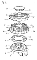
- connection part 2 substantially consists of a connection part 2, a sealing ring 4, a component 6, a closure cap part 8 and a fastening cap 10.
- the connector part 2 which is designed as a plastic injection molded part, forms a sleeve-shaped connection cap 12 for connecting the removal device to a medical container, not shown in the figures, such as e.g. an infusion bottle or a contrast medium container.
- connection cap 12 is designed for connection to such containers, which have a bottle neck-like tapered removal region, on which a removal opening is closed by a membrane is, which is secured by means of a the outer wall of the container in this removal area bead-like enclosing aluminum sleeve by means of a crimp on the container.
- connection cap 12 which has a substantially corresponding to the outer contour of the removal region inner contour, placed.
- a projection 14 arranged in the region of the open end side of the connection cap 12 on the inner wall and extending over the entire inner circumference of the firing cap 12 in the direction of its center axis surrounds the aluminum sleeve of the medical container and thus enables a form-fitting fastening of the connection cap 12 and thus of the Removal device to the container.
- connection cap 12 In order to be able to pass the projection 14 on the aluminum sleeve of the container, the wall of the connection cap 12 in the direction of its longitudinal extent distributed over the circumference several slotted, which in conjunction with a certain elasticity of the plastic material of the connection cap 12 to a flexibility of the wall in the radial direction leads, whereby the inner cross section of the connection cap 12 can be extended in the region of the open end face to re-form after its passage of the aluminum sleeve to its original cross-sectional size.
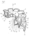
- a hollow mandrel 16 For piercing the membrane of the medical container and for producing a line connection in the container, a hollow mandrel 16 is arranged concentrically to the connection cap 12, the free and pointed end of the open side of the connection cap 12 faces. The other end of the hollow mandrel 16 opens into a flat base 18 of a guide 20, in which the component 6 is guided in the assembled state of the removal device.
- the guide 20 also forms part of the connection part 2. It is arranged on the end face of this connection cap 12 facing away from the open side of the connection cap 12.
- the guide 20 is arranged eccentrically to the connection cap 12 such that the connection cap 12 and the guide 20 connected thereto overlap only in one section.
- the base 18 of the guide 20 is annular and is bounded on both its inner and on its outer periphery by side walls which extend perpendicular to the base 18 in a direction away from the open side of the terminal cap 12 direction.
- Starting from the inner side wall of the base 18 extends parallel to the base 18 a further annular surface 22 in the direction of a central axis A of the guide 20.
- Starting from the inner periphery of the surface 22 are arranged distributed over the entire circumference locking elements 24 which perpendicular to the surface 22 are aligned in a direction away from the open side of the terminal cap 12 direction.
- the guide 20 serves to receive and hold the component 6, which is designed as the connection part 2 as a plastic injection molded part.
- the component 6 is also formed annularly corresponding to the guide 20, wherein an outer wall of the component 6 initially extends in the direction of its central axis A and then kinks such that it forms a connection surface 26 which extends radially in the direction of the central axis A of the component ,
- connection surface 26 which is parallel to the base surface 18, distributed over the circumference of ten terminals 28 are arranged with parallel to the central axis A of the component 6 longitudinal axes. These connections 28 each have a flow channel 30 parallel to the central axis A of the component 6.
- the flow channels 30 are characterized by the Led surface 26 forming wall of the component 6 and extended at the side facing away from the terminal surface 26 front side of the wall by tubular nozzle 31.
- the connections 28 form the liquid outlets of the removal device and are each designed as a Luer lock connection, so that the connections 28 with a correspondingly formed Luer lock connection z. B. with a syringe or with a hose can be connected.
- the sealing ring 4 is arranged between the guide 20 of the connection part 2 and the component 6.
- the sealing ring 4 is a rubber sealing ring with a flat annular base body 38 whose radial dimensions substantially correspond to the dimensions of the base 18 of the guide 20.
- ten knob-shaped elevations 40 extend perpendicular to the end face.
- the ridges 40 have a substantially cylindrical shape.
- the diameter of the elevations 40 is complementary to the inner diameters of the flow channels 30 arranged in the connections 28 of the component 6.
- Each of the elevations 40 is interrupted by a flow channel 42 extending in its longitudinal direction.
- the elevations 40 of the sealing ring 4 engage in the tubular socket 31 of the component 6 a.
- the planar and flat front side of the main body 38 of the sealing ring 4 is then on the base 18 of the guide 20.
- the outer wall of the component 6 lies with its inner side on the outside of the outer, the base 18 bounding wall of the guide 20 at. This engages the base 18 outwardly bounding wall, the nozzle 31 of the component 6, which come to this diametrically opposite also with the outside of the inner, the base 18 bounding wall of the guide 20 to the plant.
- the wall of the component 6, which forms the connection surface 26 with its opposite side on the surface 22 of the guide 20 is located.
- the positive fastening of the component 6 on the guide 20 or on the connecting part 2 is effected by engaging behind the locking elements 24 of the guide 20 by the locking elements 34 of the component 6. This positive locking ensures the cohesion of the connecting part 2 and component 6 and allows the other a movement of the component 6 with the sealing ring 4 disposed thereon in the guide 20 of the connecting part. 2
- the closure cap part 8 consists of an inner ring 44, on the outer circumference of which in each case ten sealing caps 48 are connected via a thin web 46.
- the webs 46 form predetermined breaking points at which the individual closure caps 48 can be released from the ring 44.
- the closure cap part 8 is arranged such that the closure caps 48 cover the connections 28 of the component 6. In each case engages in the inner lumen of the closure caps 48 arranged cylindrical pin 50 whose outer dimensions with the inner dimensions of a flow channel 30 in the Port 28 correspond to a flow channel 30. In this way, the fluid outlets of the ports 28 are sealed germ-tight.
- the ring 44 of the closure cap part 8 is in the mounted state on the free end of the wall 32 of the component 6.
- the attachment of the cap portion 8 on the component 6 takes place with the mounting cap 10.
- the mounting cap 10 forms a circular lid, wherein on an end side of the lid in the vicinity of the outer ⁇ enishs latching elements 52 are arranged which extend normal to the end face.
- the fastening cap 10 is pushed into the opening formed by the wall 32 of the component 6 such that the latching elements 52 of the fastening cap 10 engage behind the latching elements 36 which are arranged on the inside of the wall 32. In this way, the resting on the free end of the wall 32 ring 44 of the closure cap portion 8 between the wall 32 of the component 6 and the lid of the mounting cap 10 is fixed.
- connection cap 12 of the connection part 2 is inserted over the removal area of the container such that the mandrel 16 pierces the membrane of the container and the projection 14 of the connection cap 12 engages behind the aluminum collar for attaching the membrane to the container and so determines the removal device to the container.
- the component 6 and the associated sealing ring 4 is rotated in the guide 20 of the connecting part 2, that the flow path of the hollow mandrel 16 is closed by the main body 38 of the sealing ring 4, so that no liquid leak from the container can.
- the component 6 and the sealing ring 4 is rotated to the connecting part 2 so that the flow path through the hollow mandrel 16, the flow channel 42 of the sealing ring 4 and formed in the respective port 28 flow channel 30 form a fluid line from the medical container to the connected hose through which the liquid can then be supplied to a patient.
- the required rotational position of the component 6 relative to the connecting part 2 is indicated by markings 54 on the component 6, which are assigned to each of the terminals 28 and a marking 56 on the connecting part 2, wherein the respective marking 54 and the marking 56 for establishing a line connection must be made to coincide in the radial direction of the connection part 2.
- the component 6 is rotated relative to the connection part 2 so that the marking 56 and the marking 54 are radially offset from each other.
- the sealing ring 4 closes the flow path through the hollow mandrel 16, so that no liquid can escape from the container and from the outside no germs or impurities can pass through the component 6 in the container.
- the now used port 28 of the component 6 can be seen by the missing cap 48.
- another cap 48 is withdrawn from a port 38 and the process described above repeated.
- connections 28 can be provided in a contact area between the connecting part 2 and the component 6 wedge-shaped locking elements whose training the movement of the component 6 in the guide 20 in one direction only, ie clockwise or counterclockwise allowed.
- a pair of stops consisting of a arranged on the component 6 stop and a corresponding, for example, on the guide 20 second stop a beyond an angle of 360 ° beyond rotational movement of the component 6 can be excluded in the guide 20, whereby a multiple use of Connections 28 is further prevented.
Landscapes
- Health & Medical Sciences (AREA)
- Heart & Thoracic Surgery (AREA)
- Life Sciences & Earth Sciences (AREA)
- Veterinary Medicine (AREA)
- Public Health (AREA)
- General Health & Medical Sciences (AREA)
- Animal Behavior & Ethology (AREA)
- Anesthesiology (AREA)
- Hematology (AREA)
- Biomedical Technology (AREA)
- Engineering & Computer Science (AREA)
- Pulmonology (AREA)
- Pharmacology & Pharmacy (AREA)
- Medical Preparation Storing Or Oral Administration Devices (AREA)
- Infusion, Injection, And Reservoir Apparatuses (AREA)
- External Artificial Organs (AREA)
Applications Claiming Priority (1)
| Application Number | Priority Date | Filing Date | Title |
|---|---|---|---|
| DE200610040670 DE102006040670A1 (de) | 2006-08-30 | 2006-08-30 | Vorrichtung zur Entnahme von Flüssigkeiten |
Publications (2)
| Publication Number | Publication Date |
|---|---|
| EP1894555A2 true EP1894555A2 (fr) | 2008-03-05 |
| EP1894555A3 EP1894555A3 (fr) | 2008-10-08 |
Family
ID=38702076
Family Applications (1)
| Application Number | Title | Priority Date | Filing Date |
|---|---|---|---|
| EP20070015156 Withdrawn EP1894555A3 (fr) | 2006-08-30 | 2007-08-02 | Dispositif pour l'extraction de liquides |
Country Status (3)
| Country | Link |
|---|---|
| US (1) | US20080058770A1 (fr) |
| EP (1) | EP1894555A3 (fr) |
| DE (1) | DE102006040670A1 (fr) |
Cited By (3)
| Publication number | Priority date | Publication date | Assignee | Title |
|---|---|---|---|---|
| WO2014023502A1 (fr) * | 2012-08-09 | 2014-02-13 | Paul Hartmann Ag | Tubulure flexible destinée à être utilisée dans le traitement de plaies par une pression négative |
| WO2016168806A1 (fr) * | 2015-04-16 | 2016-10-20 | Becton Dickinson and Company Limited | Dispositif de transfert de fluide |
| CN106232082A (zh) * | 2014-04-16 | 2016-12-14 | 贝克顿迪金森有限公司 | 带有能够轴向地和可旋转地运动的部分的流体输送装置 |
Families Citing this family (4)
| Publication number | Priority date | Publication date | Assignee | Title |
|---|---|---|---|---|
| US20090166311A1 (en) * | 2007-12-27 | 2009-07-02 | Helvoet Pharma Belgium N.V. | Pharmaceutical closure with a laser-applied marking |
| DE102010062985A1 (de) * | 2010-12-14 | 2012-04-19 | Robert Bosch Gmbh | Flüssigkeitsentnahmemodul, Flüssigkeitstank |
| SG192312A1 (en) * | 2012-02-02 | 2013-08-30 | Becton Dickinson Holdings Pte Ltd | Adaptor for coupling to a medical container |
| CH719387A1 (de) * | 2022-01-26 | 2023-07-31 | Silberspross Gmbh | Medizinische Fluidsteuervorrichtung. |
Family Cites Families (18)
| Publication number | Priority date | Publication date | Assignee | Title |
|---|---|---|---|---|
| FR2448675A1 (fr) * | 1979-02-07 | 1980-09-05 | Nat Res Dev | Valve de distribution de doses d'un fluide d'une bouteille de reserve a un recipient recepteur |
| DK154884A (da) * | 1984-03-13 | 1985-09-14 | Medesign A S | Hjaelpeapparat til klargoerelse af injicerbare medikamenter |
| DE3627231C2 (de) * | 1986-08-11 | 1995-09-07 | Codan Medizinische Geraete | Überleitungsgerät zum Mischen von in unterschiedlichen Behältern befindlichen Medikamenten |
| US4842028A (en) * | 1987-05-13 | 1989-06-27 | Baxter International Inc. | Fluid transfer apparatus |
| DE8802488U1 (de) * | 1988-02-26 | 1989-06-29 | Bernard, geb.Kaemmerer, Ingrid, 4803 Steinhagen | Verschluß für Infusionsbehälter |
| US5595707A (en) * | 1990-03-02 | 1997-01-21 | Ventana Medical Systems, Inc. | Automated biological reaction apparatus |
| DE9300177U1 (de) * | 1993-01-12 | 1994-05-19 | Bachnick, Martina, 10827 Berlin | Behälter, insbesondere Arzneimittel-Behälter |
| US5439645A (en) * | 1993-01-25 | 1995-08-08 | Coulter Corporation | Apparatus for automatically, selectively handling multiple, randomly associated hematological samples |
| DE4408498C2 (de) * | 1993-11-16 | 1997-06-12 | Christian Eichler | Umfülleinrichtung für die Medizin und die Pharmazie |
| US5553508A (en) * | 1995-03-24 | 1996-09-10 | University Corporation For Atmospheric Research | Portable intelligent whole air sampling system |
| IT236231Y1 (it) * | 1997-11-24 | 2000-08-08 | Eurospital S P A | Dispositivo di collegamento di due contenitori di prodottifarmaceutici per effettuare il mescolamento dei prodotti in sistema |
| US6183693B1 (en) * | 1998-02-27 | 2001-02-06 | Cytologix Corporation | Random access slide stainer with independent slide heating regulation |
| US6405609B1 (en) * | 1998-02-27 | 2002-06-18 | Ventana Medical Systems, Inc. | System and method of aspirating and dispensing reagent |
| US6599484B1 (en) * | 2000-05-12 | 2003-07-29 | Cti, Inc. | Apparatus for processing radionuclides |
| US7261860B1 (en) * | 2001-10-16 | 2007-08-28 | Space Hardware Optimization Technology, Inc. | Apparatus and method for centrifugation and robotic manipulation of samples |
| JP2005523692A (ja) * | 2002-04-26 | 2005-08-11 | アボット・ラボラトリーズ | 生物学的検定において磁性粒子を処理するための構造体および方法 |
| WO2005008219A2 (fr) * | 2003-07-18 | 2005-01-27 | Bio-Rad Laboratories, Inc. | Systeme et procede permettant la detection de multiples substances a analyser |
| US7575567B2 (en) * | 2005-01-31 | 2009-08-18 | Simpkins Dale H | Multiple medication IV pump |
-
2006
- 2006-08-30 DE DE200610040670 patent/DE102006040670A1/de not_active Ceased
-
2007
- 2007-08-02 EP EP20070015156 patent/EP1894555A3/fr not_active Withdrawn
- 2007-08-30 US US11/847,386 patent/US20080058770A1/en not_active Abandoned
Cited By (4)
| Publication number | Priority date | Publication date | Assignee | Title |
|---|---|---|---|---|
| WO2014023502A1 (fr) * | 2012-08-09 | 2014-02-13 | Paul Hartmann Ag | Tubulure flexible destinée à être utilisée dans le traitement de plaies par une pression négative |
| CN106232082A (zh) * | 2014-04-16 | 2016-12-14 | 贝克顿迪金森有限公司 | 带有能够轴向地和可旋转地运动的部分的流体输送装置 |
| CN106232082B (zh) * | 2014-04-16 | 2019-03-12 | 贝克顿迪金森有限公司 | 带有能够轴向地和可旋转地运动的部分的流体输送装置 |
| WO2016168806A1 (fr) * | 2015-04-16 | 2016-10-20 | Becton Dickinson and Company Limited | Dispositif de transfert de fluide |
Also Published As
| Publication number | Publication date |
|---|---|
| EP1894555A3 (fr) | 2008-10-08 |
| DE102006040670A1 (de) | 2008-03-20 |
| US20080058770A1 (en) | 2008-03-06 |
Similar Documents
| Publication | Publication Date | Title |
|---|---|---|
| EP1763405B1 (fr) | Dispositif de deversement comprenant une seringue ou une cartouche, un capuchon de fermeture et un melangeur | |
| EP0808148B1 (fr) | Dispositif de transfert | |
| DE4414697C2 (de) | Vorrichtung zum Transferieren und Entnehmen von Flüssigkeiten aus Flaschen, Beuteln oder ähnlichen Behältnissen für medizinische Zwecke | |
| DE60210735T2 (de) | Transfervorrichtung sowie System mit einer Kappenanordnung, einem Behälter und der Transfervorrichtung | |
| EP2651471B1 (fr) | Dispositif permettant de prélever du liquide contenu dans un récipient | |
| EP0604748A2 (fr) | Manchon de trocart | |
| EP1454650A1 (fr) | Dispositif de transfer, notamment pour des fluides médicaux | |
| DE29800107U1 (de) | Schlauchkupplung für ein medizinisches Überleitungssystem | |
| DE3627231C2 (de) | Überleitungsgerät zum Mischen von in unterschiedlichen Behältern befindlichen Medikamenten | |
| EP3181245B1 (fr) | Dispositif de buse pour substances fluides | |
| EP3233016B1 (fr) | Système de connecteur ayant au moins deux ports de prélèvement | |
| DE202006011365U1 (de) | Vorrichtung zum abgeschlossenen, tropffreien und sicheren Transfer von Fluiden | |
| DE102004044288A1 (de) | Vorrichtung zur Verbindung eines rohrförmigen Teils, insbesondere einer Kanüle, mit dem Inneren einer Flasche oder dergleichen | |
| DE102006040670A1 (de) | Vorrichtung zur Entnahme von Flüssigkeiten | |
| DE102018001102A1 (de) | Behälter | |
| DE102012016936A1 (de) | Vorrichtung zur Entnahme von Körperflüssigkeiten und Verfahren zum Montieren einer solchen Vorrichtung | |
| EP2030687A1 (fr) | Dispositif de fermeture doté d'un mécanisme à déclic | |
| DE202016101947U1 (de) | Verbindungsvorrichtung zur Verbindung einer medizinischen Schlauchleitung mit einer Flasche | |
| DE3004539A1 (de) | Ventilanordnung | |
| DE102016110009A1 (de) | Vorrichtung zur Befüllung von Tanks mit Zwischenbehälter | |
| DE202016100371U1 (de) | Schlauchsystem für eine Injektionsvorrichtung | |
| DE19603632C2 (de) | Adapter für ein Fluidentnahmesystem | |
| DE4332087A1 (de) | Verschluß- und Entnahmeeinrichtung | |
| AT516438B1 (de) | Handhabungsvorrichtung sowie Verfahren zu deren Herstellung | |
| EP2006021A1 (fr) | Partie supérieure de pipetage |
Legal Events
| Date | Code | Title | Description |
|---|---|---|---|
| PUAI | Public reference made under article 153(3) epc to a published international application that has entered the european phase |
Free format text: ORIGINAL CODE: 0009012 |
|
| AK | Designated contracting states |
Kind code of ref document: A2 Designated state(s): AT BE BG CH CY CZ DE DK EE ES FI FR GB GR HU IE IS IT LI LT LU LV MC MT NL PL PT RO SE SI SK TR |
|
| AX | Request for extension of the european patent |
Extension state: AL BA HR MK YU |
|
| PUAL | Search report despatched |
Free format text: ORIGINAL CODE: 0009013 |
|
| AK | Designated contracting states |
Kind code of ref document: A3 Designated state(s): AT BE BG CH CY CZ DE DK EE ES FI FR GB GR HU IE IS IT LI LT LU LV MC MT NL PL PT RO SE SI SK TR |
|
| AX | Request for extension of the european patent |
Extension state: AL BA HR MK RS |
|
| AKX | Designation fees paid | ||
| STAA | Information on the status of an ep patent application or granted ep patent |
Free format text: STATUS: THE APPLICATION IS DEEMED TO BE WITHDRAWN |
|
| 18D | Application deemed to be withdrawn |
Effective date: 20090409 |
|
| REG | Reference to a national code |
Ref country code: DE Ref legal event code: 8566 |