EP1894604A2 - Vêtement de protection - Google Patents
Vêtement de protection Download PDFInfo
- Publication number
- EP1894604A2 EP1894604A2 EP07016582A EP07016582A EP1894604A2 EP 1894604 A2 EP1894604 A2 EP 1894604A2 EP 07016582 A EP07016582 A EP 07016582A EP 07016582 A EP07016582 A EP 07016582A EP 1894604 A2 EP1894604 A2 EP 1894604A2
- Authority
- EP
- European Patent Office
- Prior art keywords
- gas
- protective suit
- ring
- personal protective
- person
- Prior art date
- Legal status (The legal status is an assumption and is not a legal conclusion. Google has not performed a legal analysis and makes no representation as to the accuracy of the status listed.)
- Granted
Links
Images



Classifications
-
- A—HUMAN NECESSITIES
- A62—LIFE-SAVING; FIRE-FIGHTING
- A62B—DEVICES, APPARATUS OR METHODS FOR LIFE-SAVING
- A62B17/00—Protective clothing affording protection against heat or harmful chemical agents or for use at high altitudes
- A62B17/001—Adaptations for donning, adjusting or increasing mobility, e.g. closures, joints
-
- A—HUMAN NECESSITIES
- A62—LIFE-SAVING; FIRE-FIGHTING
- A62B—DEVICES, APPARATUS OR METHODS FOR LIFE-SAVING
- A62B17/00—Protective clothing affording protection against heat or harmful chemical agents or for use at high altitudes
- A62B17/006—Protective clothing affording protection against heat or harmful chemical agents or for use at high altitudes against contamination from chemicals, toxic or hostile environments; ABC suits
Definitions
- the present invention relates to a personal protective suit for protecting a person in a dangerous environment, comprising an outer shell substantially completely surrounding the person, and gas supply means by means of which a gas can be released inside the outer shell to supply the person with inhalation gas.
- Personal protective suits of this type are known from industrial production as well as from research and are used when a stay of a person to carry out a work or the like is necessary within a particular danger environment in which direct contact of the person with the environment must be avoided.
- a hazard environment is any environment in which hazardous dusts, gases, droplets or the like with a certain level of concentration and / or probability are present, as well as any environment in which there is a danger of coming into contact with these dusts.
- this is thought of premises in which toxic or carcinogenic substances, hazardous biological materials, viruses or similar substances are.
- Particularly well-known personal protective suits are used in laboratories, for example for the production of medicaments or the like, in which the person protected by the protective suit has to deal with the hazardous substances.
- the gas supply means are then connected via a hose to an external gas source of the laboratory, which continuously provides inhaled gas at a predetermined pressure, which is released from the gas supply means inside the personal protection suit.
- the supplied Inhalation gas is partially inhaled by the person and, on the other hand, exits the personal protective suit together with the person's exhalation gas through seams of the suit, crevices around the cuffs and trouser leg ends, through other openings or through special outlet gaps or non-spring-loaded exhalation valves.
- the flow rate of the supplied inhale gas is adjusted to a correspondingly high value in order to ensure a continuous flow of clean natural gas from all openings of the personal protection suit and in this way to prevent the penetration of hazardous substances through openings of the personal protection suit.
- the person in the suit is essentially complete, ie substantially "from head to toe," in a constantly renewing environment of clean breathing gas.
- the outer shell known personal protective suits Although some protection against ingress of hazardous substances, but it is very heavy and relatively stiff, so that the work in such a personal protective suit is associated with high effort and low freedom of movement.
- the comfort of known personal protective suits is additionally affected by the fact that they are generally made only in one or a few clothing sizes and due to the high manufacturing cost of such suits an adaptation to the clothing size of a particular person is not possible or only with great effort.
- conventional personal protective suits are very uncomfortable to wear in one or a few standard sizes, especially for smaller or larger people. Such size differences are particularly noticeable in the hands or feet of people enclosing areas of the protective suit. If several people use one and the same protective suit alternately together, it must be purchased for a suit whose size, in particular in the glove sections or the shoe sections to the size the largest person is adjusted.
- the described personal protective suits also have security-related disadvantages.
- the person wearing the protective suit is protected in the manner described above from direct contact with hazardous substances in the vicinity of the personal protection suit with continuous supply of inhalation gas, but this protection is relatively quickly eliminated if the gas supply is interrupted due to a fault.
- the entry of hazardous substances from the environment into the personal protective suit preventing flow of inhaled gas from the openings of the outer shell abruptly stops and there is a risk that said substances get inside the outer shell before the person concerned the Passenger protection suit filed and entered a safe room or before the person reaches a cleaning chamber or the like in the personal protection suit.
- cost-intensive measures have to be taken to ensure a fail-safe gas supply or a certain security risk must be accepted.
- a personal protective suit for protecting a person in a dangerous environment comprising an outer shell substantially completely surrounding the person, and gas supply means by means of which a gas can be released inside the outer shell around the person supply with inhaled gas, wherein at least one gas outlet valve is provided on the outer shell, which is designed as set to a predetermined target pressure relief valve to set at gas supply an internal pressure inside the personal protection suit substantially to this target pressure.
- the personal protection suit By using a set to a predetermined target pressure relief valve that adjusts an internal pressure of the personal protection suit substantially to this target value with gas supply, it is possible in the personal protection suit according to the invention to maintain a substantially constant and definable in advance target pressure inside the personal protection suit.
- the target pressure to a value that is in particular only slightly greater than the environmental pressure surrounding the personal protective suit, so that the ensured, substantially constant pressure difference between internal pressure and ambient pressure, a readily controllable flow of uncontaminated gas from inside the outer shell through the at least one pressure relief valve takes place.
- the pressure and flow conditions within the personal protection suit can be ensured much more securely and specified more precisely.
- the at least one gas outlet valve switches to a blocking state in which a flow of gas through the gas outlet valve is substantially blocked, and switches when the internal pressure exceeds a second threshold value , in an on-state in which a Outflow of gas from the inside of the personal protection suit is allowed through the gas outlet valve.
- the at least one gas outlet valve in the blocking state when falling below the first threshold pressure measures are taken in the event of a pressure drop within the personal protection suit to prevent further pressure drop of the internal pressure, or at least slowing down significantly.
- the described configuration of the preferred embodiment comes into play in particular in an accident in which the supply of the personal protection suit with inhaled gas is interrupted due to a fault or at least significantly reduced. Due to the outflow of the gas from the gas outlet valves, a fall in the internal pressure will occur in such a case, resulting in a reduction of the outflow velocity of the gas through the at least one gas outlet valve.
- the at least one gas outlet valve switches into the blocking state when it falls below this threshold value and prevents or prevents reduces on the one hand a further pressure drop inside the personal protection suit and on the other hand blocks the entry of contaminated gas from the environment.
- a predetermined overpressure thus remains in such an accident, in order to protect the person in question for a certain period of time in the atmosphere of inspiration gas.
- This period of time may either be sufficient to bridge a temporary interruption of the gas supply or may give the person time to restart the gas supply or to leave the danger zone.
- this period of time can also be set up so that the person concerned has sufficient time to take standard decontamination measures.
- a personal protective suit according to the invention provides a more reliable protection in the danger environment or / and enables the reduction of the effort to ensure an uninterrupted supply of inhaled gas.
- the first threshold pressure is equal to or less than the predetermined target pressure
- the second threshold pressure is equal to or greater than the predetermined target pressure.
- the exhaust valve reliably regulate the internal pressure independently to the target pressure or a control range in the vicinity of the target pressure.
- the first and second threshold pressures are different from each other, it is possible to reduce the number of switching operations of the at least one gas outlet valve.
- a difference between the target pressure and an ambient pressure of the personal protection suit or a difference between the target pressure and a predetermined normal pressure between about 1 mbar (100 Pa) and about 10 mbar (1000 Pa), preferably between about 5 mbar (500 Pa) and about 7 mbar (700 Pa) and more preferably between about 4.0 mbar (400 Pa) and about 4.5 mbar (450 Pa).
- the safety of the personal protection suit according to the invention in particular in the event of a sudden failure of the gas supply, is further increased if, in the blocking state of the at least one gas outlet valve, substantially no gas escapes from the interior of the personal protection suit. In the event of a total failure of the gas supply is then the above-mentioned period of time during which in the personal protective suit, the protective gas atmosphere is maintained, even greater.
- the gas supply means have a backflow blocking device which blocks a flow of gas opposite to the gas supply direction.
- the gas supply means further comprise a provided on the outer shell gas inlet portion which is connected or connectable to an external gas source
- the sudstromsperr Marie may comprise a arranged in the gas inlet portion check valve in a structurally simple embodiment.
- the at least one gas outlet valve may have tamper-evident means which substantially prevent or indicate a change and / or removal of the gas outlet valve.
- tamper-evident means which substantially prevent or indicate a change and / or removal of the gas outlet valve.
- such a tamper-evident means can have at least one detachable engagement projection on which a tool for mounting or / and disassembling the gas outlet valve engages.
- the removable attack projection can be removed after installation of the original gas outlet valve, so that the gas outlet valve can then no longer be removed or replaced without a trace.
- a personal protective suit for protecting a person in a dangerous environment, comprising an outer envelope substantially completely surrounding the person and gas supply means by means of which a gas inside the person
- the outer shell is releasable to supply the person with inhaled gas
- the gas supply has at least one arranged in the head region of the personal protection suit gas discharge opening and wherein the at least one gas discharge opening comprises a flow calming arrangement which distributes the gas over a surface area and / or distributed over several directions releases.
- the gas discharge opening is thus arranged in the head region of the protective suit in which the inhaled gas is significantly required.
- the gas is released via the flow calming arrangement, which calms the flow of gas out of the gas discharge opening.
- the sensation of drafts for the person to be protected is avoided or at least significantly mitigated.
- the distributed release of the gas over a surface area or / and over several directions a direct and punctual influx of a certain area of the person with a relatively high flow rate is avoided and a Cold, stress, dehydration and the like can be prevented.
- the wear comfort of the personal protection suit according to the invention is also significantly improved by this measure.
- the flow calming arrangement comprises an air-permeable solid-state material, in particular a porous or textile or net-like material or the like.
- a material offers a structurally simple way of distributing the gas flow over a surface area or / and over several directions and thus preventing the person from feeling excessive draft.
- such a material contributes to the damping of flow noise and thus further reduces the noise pollution within the personal protection suit.
- the flow calming arrangement may have an overall passage cross section which is larger, in particular more than approximately 2 times larger than the total passage cross section of a gas guide connected to the gas discharge opening. Due to the considerably larger overall passage cross-section, the flow velocity within the flow calming arrangement is significantly reduced and the flow is thus calmed.
- the flow calming arrangement comprises an air-permeable material web, in particular textile or net web, which is arranged inside the outer shell facing the head of the person, and that the gas in a region between the outer shell and the air-permeable material web is introduced so that it is released through the air-permeable material web into the head area of the personal protection suit.
- an air-permeable material web is also of relatively low weight and relatively inexpensive to produce and can be accommodated comfortably in the interior of the personal protection suit without much space.
- the air-permeable material web has a first material web portion, which is arranged facing the neck and the rear head region of the person, and has a second material web portion, which faces the upper head region of the person facing, wherein the first web section has a lower air permeability than the second web section.
- the first material web section is formed from a textile material, in particular a felt material
- the second material band section is formed from a mesh material, for example a plastic mesh or the like.
- a personal protective suit for protecting a person in a dangerous environment, comprising an outer shell substantially entirely surrounding the person, and gas supply means by means of which a gas can be released inside the protective suit to the person with inhalation gas too
- the gas supply means comprise a filter device which filters the gas to be supplied, and wherein the filter device is disposed within the outer shell.
- the filter device By the arrangement of the filter device within the outer shell, the filter device itself is protected against contamination by potentially present in the danger environment hazardous substances. On the one hand, this makes it easier to clean the entire personal protective suit, since the decontamination of the filter device and possibly its associated connection means can be omitted, and on the other hand ensures reliable allocation of the filter device to a specific personal protective suit, so that when leaving the danger environment and cleaning / maintenance of the personal protection suit the filter device is always carried and thus can be reliably maintained or replaced as needed. There are therefore advantages with regard to the overall safety of the personal protection suit and with regard to a reduction of the cleaning / sterilization effort.
- the filter device is mounted on an inner side of the outer shell, so that it is located at a defined position where it is not disturbing especially for the person. If the filter device is accommodated in an openable and closable pocket of the personal protection suit arranged on the inside of the outer shell, the contamination protection of the filter device can be further improved, the filter device remaining accessible for maintenance purposes through a closable pocket opening.
- the gas supply means further includes a gas inlet portion provided on the outer shell which is connected or connectable to an external gas source
- a gas guiding portion must be provided be formed between the gas inlet portion and the filter device substantially gas-tight, to ensure that no unfiltered gas enters the interior of the personal protection suit. Therefore, according to one embodiment, it is proposed that the filter device be adjacent to and connected to the gas inlet section in order to filter the gas supplied by the external gas source. The addressed gas guide between the gas inlet section and the filter device can then be omitted, so that the gas supply means are simplified as a whole.
- a portion from the outlet of the filter device to a gas discharge port for releasing the inhalation gas can be provided without much sealing effort, since a release of filtered gas in the personal protective suit is unproblematic or desired.
- the filter device can even deliver the filtered gas directly into the interior of the personal protection suit.
- the gas supply means have at least one gas discharge opening which discharges the gas into the interior of the personal protection suit, and furthermore have at least one gas guide which connects the filter device to the at least one gas discharge opening. Then discharges the gas guide into the above pocket for receiving the filter device, the bag is an advantageous dual function to go on the one hand receives the filter device for protection against contamination and on the other hand in the closed state, the exiting the filter device filtered gas into the gas conducts and thus forms a connection of the gas guide to the filter device.
- the filter device is operatively connected to the gas inlet portion by means of a releasable coupling operatively substantially gas-tight.
- the releasable coupling then provides on the one hand a gas-tight connection between the gas inlet section and the filter device, on the other hand, can be easily manually released to service / replace the filter device.
- a personal protective suit for protecting a person in a dangerous environment, comprising an outer shell which substantially completely surrounds the person and gas supply means, by means of which a gas inside the person Personal protective suit is releasable to supply the person with inhaled gas
- the gas supply means further comprise a provided on the outer shell gas inlet portion which is connected or connectable to an external gas source, wherein the gas inlet portion has a channel for passing gas, which from an outside the Outer shell extending outer channel piece, an inner channel piece extending within the outer shell and a connecting channel piece which connects the outer channel piece and the inner channel piece to one another, and wherein st the outer channel piece is substantially parallel to a gas inlet portion adjacent portion of the outer shell.
- the problem encountered with known personal protective suits is encountered that an outer channel piece of the gas inlet portion and a piece of tubing connected thereto are pivoted downwards or otherwise towards the personal protective suit due to their own weight or other forces acting in that area.
- Such pivotal movement has resulted in known personal protection suits to a heavy load of the gas inlet portion adjacent portion of the outer shell.
- the outer channel piece is aligned substantially parallel to a section of the outer shell adjacent to the gas inlet section, so that lever forces acting on the gas inlet section become clear be reduced.
- the outer channel piece and thus also a connected thereto hose section in the personal protection suit according to the invention is not disturbing from this, so that the risk of collision of these sections with objects or the like is reduced in the environment.
- the outer channel piece and the inner channel piece may be spaced apart and substantially parallel to the portion of the outer shell adjacent to the gas inlet portion.
- the inner channel piece is not too far away in the direction of the person from, so that the channel piece and an attached element of the personal protection suit (for example, a filter device or the like) can be accommodated in the suit to save space.
- the connecting channel piece has a substantially continuously curved course. In this way, the flow path of the inspiratory gas from the outer channel piece is straightened by the connecting channel piece to the inner channel piece and executed substantially without sharp edges. It has been shown that in this way the flow noise in the region of the gas inlet section can be significantly reduced.
- the gas inlet section comprises an outer housing half containing the outer channel piece and an inner housing half containing the inner channel piece, that the outer shell has a through opening associated with the gas inlet portion and that the two housing half are fastened to each other in such a way that the connecting channel piece the Passage through opening and an edge of the passage opening circumferentially received and sealed between the outer and the inner housing half.
- a personal protective suit for protecting a person in a dangerous environment, comprising an outer shell substantially completely surrounding the person and gas supply means by means of which a gas inside the person Personal protective suit is releasable to provide the person with inhalation gas, wherein the outer shell is formed of a bi-elastic material.
- the outer shell according to the invention provides a significantly improved freedom of movement and a more comfortable seat and thus allows a longer and more comfortable wearing the suit.
- the Bielastiztician the outer shell is usually also accompanied by an improvement in the durability of the suit, as well as a greater number of occurring during the lifetime of the suit kinking movements in the material of the outer shell does not lead to breakage or tearing of the material.
- bi-elastic material has been found to be a polyurethane material with a textile reinforcement.
- the outer shell according to the invention has also been found to be particularly breathable and particularly advantageous to clean / sterilize.
- the textile reinforcement is made of a
- a proportion of polyester in the outer shell material will be between about 40% and about 80%, preferably between about 50% and about 65%, and most preferably about 58%; remaining material content is formed essentially of polyurethane.
- the outer shell may be formed of a material which carries a polyurethane coating on both sides of a polyester knitted fabric.
- the material marketed under the brand name NIMBA-Tex comes into consideration, which is composed of a polyester knit and a proportion of 42% of a polyurethane coating to a proportion of 58%, wherein the polyurethane coating on both sides of the polyester Is arranged.
- NIMBA-Tex was developed and used as a wet protection mat for mattresses, cushions and bedding to protect against moisture and dirt in the care sector.
- NIMBA-Tex is waterproof, chemical-resistant, reliably prevents the passage of harmful substances, but at the same time is breathable, easy to clean, autoclavable, especially at high temperatures, sufficiently tear-resistant, hygiene-tested, recommended for allergy sufferers and durable even with frequent use.
- the material is bi-elastic and relatively light and therefore offers very high wearing comfort.
- a personal protective suit for protecting a person in a dangerous environment, comprising an outer envelope substantially completely surrounding the person and gas supply means by means of which a gas inside the person Personal protective suit can be released to provide the person with inhalation gas, wherein a arranged in the front head portion of the personal protection suit, see-through window is formed of a flexible, transparent plastic material.
- a window of a motor vehicle folding roof has been recognized as an advantageous plastic material.
- such a material is very robust and, on the other hand, offers a low weight and sufficient protection against the harmful substances in question.
- a personal protective suit for protecting a person in a dangerous environment, comprising an outer shell substantially completely surrounding the person, and gas supply means by means of which a gas inside the person Personal protective suit is releasable to supply the person with inhaled gas, wherein the outer shell at least one, in particular of a sleeve portion or a trouser leg portion formed tube portion and at least one hose portion associated with the connector part, in particular in the form of a glove or a shoe, said at least one Connecting part is connected via a releasable coupling operatively substantially gas-tight to the hose portion, and wherein the releasable coupling comprises a first ring, on which an edge portion of the connecting part substantially gas is tightly secured and on the outer periphery of an edge portion of the hose portion along its entire circumference is applied, and comprises a second ring, the first Ring surrounds
- a personal protective suit constructed in this manner offers the possibility of connecting a connection part, in particular gloves and / or shoes, to the personal protective suit by means of a detachable coupling, so that it can be disconnected or coupled in a simple manner if required.
- a connection part in particular gloves and / or shoes
- An essential aspect of the coupling between hose section and connection part according to the invention is that the edge section of the hose section is received and fastened substantially gas-tight between the outer circumference of the first ring and the inner circumference of the second ring. Accordingly, without providing any additional coupling means to the hose portion, the edge portion of the hose portion (i.e., particularly the edge portion of the sleeve portion or the trouser leg portion) can be directly attached to the fitting portion by means of the releasable coupling.
- the coupling of the hose section to the connection part is in a simple operation possible by the edge portion of the tube portion is pulled over the outer circumference of the first ring and then the second ring is pushed over the first ring, so that the tube portion is securely and gas-tightly held between the two rings along its entire circumference.
- the coupling between the rings or the tube section is in particular a frictional coupling.
- Such an O-ring seal can also increase the friction between the 3 elements, first, second ring and tube section, i. ensure the tight fit of these elements to each other, and thus prevent unintentional release of the coupling.
- the O-ring seal extends in an annular groove of the first and / or second ring, so that the O-ring seal can be securely held in its desired position.
- the detachable coupling of such a personal protective suit may also comprise a first ring, around the outer periphery of which a peripheral portion of the connecting part and an edge portion of the hose portion are guided, and a second ring surrounding the first ring, wherein the Edge portion of the connecting part and the edge portion of the hose portion between the outer periphery of the first ring and the inner periphery of the second ring are substantially gas-tight received and fixed.
- the edge portion of the connecting part is pulled around the outer circumference of the first ring and thus releasably attached to the first and second ring.
- one or more O-ring seals can also be provided in the case of a coupling according to the second alternative, which may, if desired, extend for fixing the position in an annular groove of the first and / or the second ring in order to further improve the frictional engagement of the coupling.
- the edge portion of the connection part and the edge portion of the hose portion may overlap each other in the axial direction with selectable degree of overlap, whereby even more secure connection and sealing of the coupling and at the same time a length adjustability of the hose portion is provided.
- the two alternative objects according to the seventh aspect of the invention can be particularly advantageously realized on the same personal protective suit, for example, in the coupling of the shoes, the first ring according to the first alternative is attached to an edge portion of the respective shoe, while in the coupling of Gloves, an edge portion of the gloves according to the second alternative is placed around the first ring and thus clamped with the edge portion of the sleeve portion between the two rings.
- both alternatives may be provided in each case that the first ring has a conical outer peripheral surface, or / and the second ring has a conical inner peripheral surface.
- the inventive coupling according to the seventh aspect of the present invention is also particularly simple and inexpensive to manufacture, when the second ring is formed continuously in the circumferential direction. Advantages in terms of manufacturing costs and in terms of the weight of the coupling and thus the entire personal protective suit are also achieved when the first and / or the second ring of plastic or a light metal is / are.
- the rings of the coupling are particularly easy to produce (eg by turning) and to use, if they have a substantially circular shape.
- the first and the second ring have a shape deviating from a circular shape, in particular substantially oval, a substantially elliptical or substantially egg-shaped ring shape.
- a ring shape corresponds to the natural body shapes of the user in the areas in which the couplings are while wearing the personal protection suit, much better than a circular shape, so that in this way the comfort of the personal protection suit can be further improved.
- the rings thus formed are less bulky and so less disturbing to the user during the work.
- the coupling according to the seventh aspect of the present invention may be configured such that the fitting part and / or the hose portion is secured to the first and / or the second ring by at least one locking screw. In this way it can be prevented with even greater reliability that the coupling dissolves undesirable during work in a hazardous environment and thus causes the risk of contamination.
- such a fixation by means of at least one safety screw can reliably prevent the outer ring from inadvertently from the inner ring is withdrawn when the user stretches or if for other reasons train on the hose section of the personal protection suit is exercised.
- grub screws are preferably used, so that the screws do not protrude or only slightly over a surface of the ring.
- the at least one locking screw passes through a through hole of the second ring in threaded engagement with a thread of the through hole and is screwed against a stop portion of the first ring.
- a further advantageous development of the fixation means of at least one locking screw provides that the abutment portion of the first ring comprises a recess, in particular an annular groove surrounding the first ring, in which the screw in its securing position positively engages.
- the engagement of the screw in such a recess in addition to a possible clamping engagement provides a secure positive locking of the locking screw on the first ring and thus contributes to a further increase in the reliability of the coupling against unintentional release.
- the above-described possibilities of securing the coupling by means of screw locking does not lead to a significant complication of the operation of the coupling.
- the above-described operating steps for closing and opening the coupling remain substantially unchanged, but when closing the coupling after the sliding of the rings on the at least one locking screw is tightened and before opening the coupling, the at least one locking screw is to be solved. If the at least one locking screw is not completely screwed out of its thread during release, then it can be held captive on the second ring until it is used again.
- a personal protective suit according to an embodiment of the present invention is indicated generally at 10. It comprises an outer shell 12, which arms, legs, trunk and a part of the head substantially completely enveloped, a viewing window 14, gloves 16, and shoes 18. About a gas-tight zipper 20, the outer shell 12 can be opened so far that a person on This opening can easily get into the suit 10 and get out of this.
- the outer shell 12 is formed of a polyurethane material having a textile reinforcement of a polyester knit, which under the Designation NIMBA-Tex for applications in the field of care as a bed base is sold.
- the material is cut according to the desired shape of the outer shell 12, sewn and glued and / or welded.
- the viewing window 14 is formed from a flexible, transparent plastic plate, as it also comes as a window material for motor vehicle folding roofs used.
- the viewing window 14 extends over almost the entire head region of the personal protection suit 10, while it has a relatively low weight at the same time. With the outer shell 12, the viewing window is sewn, glued or / and welded.
- the personal protective suit 10 is connected via a hose 22 to an external gas source 24, by means of which the interior of the personal protection suit 10 is supplied with an inhaled gas, so that in the interior of the personal protection suit 10 is a person to be protected substantially completely enveloping atmosphere of inhaled gas created.
- the hose 22 is connected to gas guide means, generally indicated at 26 in FIG. 1, which guide, filter and release the inspiratory gas into the interior of the personal protective suit and release it at a desired location inside the personal protection suit 10.
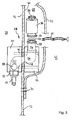
- the gas guide means 26 comprise a gas inlet section 28 penetrating the outer shell 12 and a filter device 30, a gas guide 32 and a gas release arrangement 34 in the head region of the personal protection suit 10 through the gas inlet portion 28 into the interior of the personal protection suit 10, is filtered in the filter device 30, flows through the gas guide 32 to the gas release assembly 34 and is released there in the interior of the personal protection suit 10 in the head area.
- the personal protective suit 10 has gas outlet sections 36 at at least six rear lateral locations, on which gas outlet valves are to be described later, which, depending on an internal pressure in the personal protective suit 10, gas from the interior into the environment let flow out.
- the gas inlet section 28 has an outer housing half 40 facing the danger environment 38 and an inner housing half 44 facing the interior 42 of the personal protective suit 10, which housing a section of the outer sheath 12 between them.
- the two housing halves 40, 44 attached to each other, so that the intermediate portion of the outer shell 12 is clamped between the housing halves 40, 44 and held.
- connecting channel piece 50 In the clamped between the housing halves 40, 44 portion of the outer shell 12, this has an opening 48 through which a connecting channel piece 50 is guided.
- the connecting channel piece 50 has an approximately S-like shape and merges at its opposite ends into an outer channel piece 52 projecting into the environment 38 or into an inner channel piece 54 projecting into the inner space 42. In this case, both the outer channel piece 52 and the inner channel piece 54 parallel to the gas inlet portion 28 adjacent portion of the outer shell 12th
- the connecting channel piece 50 is indicated only schematically in FIG. 3 by dotted lines and is formed in a suitable manner in the interior of the two housing halves 40, 44.
- so-called labyrinth disks are used, which are used in each case half and when screwing the two Housing halves 40, 44 are assembled to the direction indicated in Figure 3 connecting channel piece 50.
- the surrounding the connecting channel portion opening 48 in the outer shell 12 is thereby fully clamped between the housing halves 40, 44, in particular between adjacent labyrinth disks of the housing halves 40, 44, so that a reliable seal against leakage of gas from the suit 10 and against an intrusion of hazardous substances is ensured.
- a check valve which is disposed at a suitable position in the gas flow path of the gas inlet portion 28 and prevents a flow of gas in a direction from the inner channel piece to the outer channel piece.
- the outer channel piece 52 has a standardized hose coupling 56, to which a gas hose 22 can be connected or disconnected with simple manipulations.
- the inner channel piece 54 has an end flange 58, which is adapted to an end flange 60 of the filter device 30.
- an O-ring seal 64 With the interposition of an O-ring seal 64, the end flange 60 of the filter device 30 can be applied to the end flange 58 of the inner channel piece 54 and the two flanges 58, 60 can then be enclosed by a clamp 66 and coupled to each other in a gastight manner.
- the clamp 66 By means of the clamp 66, the filter device 30 is thus gas-tight and interchangeable connected to the gas inlet portion 28.
- a screw connection can also be used for the coupling between the inner channel piece 54 and the end flange 60.
- the filter device 30 used is preferably a replaceable sterile filter cartridge of the type KA02PFRP8 (manufacturer: Pall GmbH), which has hitherto been developed and marketed for use in laboratory equipment.
- Such filter cartridges 30 have a relatively small size, so that they can be accommodated advantageously in the interior of the personal protection suit 10, and are operable at relatively low pressure. Due to a large flow cross-section within the filter cartridge 30, these filter cartridges 30 operate with respect to conventional filter devices with significantly reduced noise and at the same time allow the reliable filtering of the supplied inhalation gas.
- the inner housing half 44 with the inner channel piece 54 and the filter device 30 with their associated connection means 60, 64, 66 are arranged inside a pocket 68 which is arranged between an inner side 70 of the outer shell 12 and a pocket wall 72 is formed.
- the pocket wall 72 is formed of the same material as the outer shell 12 and is connected via a seam 74 with the inner side 70 of the outer shell 12.
- the pocket 68 can be opened and closed by means of a zipper 76, so that in a normal operating state with the zipper 76 closed, the filter device 30 and the inner housing half 44 are jointly protected against contamination in the pocket 68.
- the pocket 68 merges into the gas guide 32, which leads the gas emerging from the filter device 30 to the gas release arrangement 34 in the head region of the personal protection suit 10.
- the gas guide 32 is constructed of a hose also formed from the material of the outer shell 12, which continues from the pocket wall 72 continuously. By a central seam 80, two opposite walls of the hose of the gas guide 32 are sewn together on the outer shell 12, so that the gas guide 32 is divided into two hoses guided side by side.
- a plastic hose in particular a silicone hose, may be guided in the gas guide 32 and the seam may optionally be dispensed with.
- the gas guide 32 opens in a head region of the personal protection suit 10 in the gas release assembly 34.
- the gas release assembly 34 comprises a substantially rectangular felt web 82 which is sewn along two opposite longitudinal edges 84 on the outer shell 12 and at its the gas guide 32 adjacent longitudinal edge 86 with one of the outer shell 12 removed wall of the gas guide 32 is sewn. Along the remaining edge 90 of the felt web 82 this is sewn to a net 92 of a plastic grid. The edges of the net web 92 not sewn to the felt web 82 are sewn to the outer shell 12.
- the gas release arrangement 34 is arranged on the outer shell 12 such that the felt web 82 faces the rear head region and the neck of a person and the net web 92 faces an upper head region of the person.
- the sections 82 and 92 illustrated in FIG. 4 can also be realized with felt or both with mesh or section 92 can be made with felt and section 82 with mesh.
- gas leaving the filter device 30 flows out of the pocket 68 into the gas guide 32 and from there flows past the felt web 82 and behind the web 92, i.e., downstream of the web. in a flat space between the felt web 82 and the net web 92 on the one hand and the outer shell 12 on the other. Due to the defined air permeability of the felt web 82 and the net web 92, the inhaled gas finally flows through the two webs 82, 92 and is distributed over the surfaces of these webs 82, 92, uniformly and substantially free of draft in the interior of the personal protection suit 10.
- Each gas outlet section 36 has an overpressure valve shown in FIGS. 5a and 5b which depends on a pressure in the interior 42 of the personal protection suit 10 or in dependence on a pressure difference between a person Internal pressure in the interior 42 and an ambient pressure in the environment 38 changes its passage cross-section.
- the pressure relief valve 94 shown in Figures 5a and 5b comprises a cylindrical inner housing 96 which is guided through a correspondingly sized opening 98 in the outer shell 12.
- a flange portion 100 encircling the inner housing 96 rests on the inside of the edge portion of the outer shell 12 that surrounds the opening 98.
- An outer casing 102 is screwed onto the outer periphery of the inner casing 96 from the outer side 38 so that the edge of the opening 98 between a flange portion 103 of the outer casing 102 and the flange portion 100 of the inner casing 96 is substantially gas-tightly clamped and held.
- a valve plate 106 may settle so that it completely closes a gas passage 108 formed in the interior of the inner housing 96.
- the valve disk 106 has at its center a vertically projecting guide pin 110, which is guided in a guide cylinder 114 held by webs 112 of the housing 96 in the center of the gas passage 108.
- a spring 116 is supported on the one hand on an inner side of the outer housing 102 and on the other hand in the center of the valve disk 106. In this case, the spring 116 is biased so that it spans the valve disk from the inside of the outer housing 102 and thus to the ring seal 104 back. The spring 116 thus biases the pressure relief valve 94 in the direction his closed position.
- the pressure relief valve 94 is closed and prevents both leakage of gas from the interior 42 as well as penetration of substances from the environment 38th Wenn Anlagen Continuous supply of inhalation gas in the interior 42 of the personal protection suit 10 an overpressure is established, which exceeds the threshold value, the valve plate 106 lifts against the bias of the spring 116 from the ring seal 104 and allows gas to escape from the personal protection suit 10 through the gas passage 108th , through the gap between the valve plate 106 and ring seal 104 and then through large openings 118 on the circumference of the outer housing 102.
- variable passage cross-section ie a variable gap width between valve plate 106 and ring seal 104, resulting in a fast and self-regulating adjustment of the internal pressure can be done.
- the pressure relief valve 94 closes completely and thus maintains an overpressure in the interior 42 of the personal protection suit 10 corresponding to the bias of the spring 116.
- the flange portion 100 has four cylindrical protrusions 120 to which a corresponding tool for mounting or dismounting the overpressure valve 94 can engage.
- the projections 120 are formed as well as the housing 96 made of plastic and can be easily separated, for example by means of a knife to after installation of the pressure relief valve 94 unauthorized removal of the valve to prevent.
- bores in particular two bores, may be provided on the flange portion 100 as engagement points for a corresponding tool.
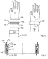
- FIGS. 6 to 10 illustrate a coupling system according to the invention for gloves 16 or shoes 18 on sleeves or trouser legs of the outer shell 12.
- the coupling comprises a first ring 124 with a tapering towards the sleeve 123 outer peripheral surface 126 and a second ring 128 with a to Glove 16 towards the inner circumferential surface 130.
- the first ring 124 has in its outer peripheral surface 126 two mutually parallel circumferential grooves 132, wherein in a circumferential groove 132, an O-ring 134 is inserted.
- the glove 16 For coupling the glove 16 to the sleeve edge 122, the glove 16 is pulled with its opening edge over the first ring 124 until a circumferential bead 136 provided on the opening edge of the glove 16 is inserted into the circumferential groove 132 bearing no O-ring 134.
- an O-ring 134 which is slightly overlapped by the opening edge of the glove 16 may be inserted in the second circumferential groove 132.
- the sleeve edge 122 is at least as far pulled over the first ring 124 until it overlaps the O-ring 134 (see also Figure 7).
- the sleeve edge 122 can also be pulled further over the first ring 124 and, if desired, extend beyond it, so that a desired sleeve length can be adjusted comfortably in this way.
- the ring 128 is pushed in the axial direction from the side of the sleeve over the first ring 124.
- these gradually approach each other when pushing over the two rings 124, 128 and clamp between the opening portion of the glove 16 and the sleeve edge 122 with their respective seals 134, 136 safely .
- the second ring 128 is slid completely over the first ring 124, as illustrated in the right-hand illustration of FIG. 6 and FIG. 7, respectively, the glove 16 and the sleeve of the outer shell 12 are securely and dust-tightly coupled to each other.
- the said steps are respectively reversed, i. the second ring 128 is deported in the direction of the sleeve 123 from the first ring 124 and then the glove 16 and the sleeve edge 122 are detached from the first ring 124.
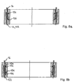
- FIG. 8 a shows a variant of the coupling system according to the invention, in which the circumferential bead 136 of the glove 16 engages in the circumferential groove 132 remote from the glove and the O-ring seal 134 lies in the circumferential groove 132 closer to the glove 16.
- the opening edge of the glove 16 and the sleeve edge 122 are then overlapped between the two rings 124, 128, thereby providing additional sealing of the coupling.
- FIG. 8b shows a further variant of the coupling system according to the invention, in which an engagement of a circumferential bead of the glove 16 in a groove of the first ring is not provided, or the glove 16 does not have a circumferential bead of the type described above.
- an O-ring seal 134 is inserted in both circumferential grooves 132 and both the opening edge of the glove 16 and the sleeve edge 122 overlap both O-ring seals 134.
- the two Fabric layers of the glove 16 and the sleeve edge 122 are thus clamped in closed coupling mainly in two areas, namely in each case between one of the O-ring seals 134 and the inner circumference of the second ring.
- the degree of overlap of the opening edge of the glove 16 and the sleeve edge 122 with each other and / or with the rings 124, 128 in all variants according to Figure 7 or Figures 8a and 8b can be freely selected as needed to change the sleeve length or / and improve the seal on the coupling.
- FIGS. 9 and 10 show a coupling system according to the invention for coupling a shoe 18 to an edge section 138 of a pant leg 139 of the outer shell 12.
- the coupling system has a first ring 124 'with an outer peripheral surface 126' tapering towards the shoe 18 and a second ring 128 '. with an outer circumferential surface 130 'which widens toward the trouser leg 139.
- the first ring 124 ' is formed of a light metal and fixed by means of an adhesive bond to the upper edge portion of the shaft of the shoe 18.
- an O-ring seal 134 ' is an outer circumferential surface 126 'extending circumferential groove 132'.
- FIG. 10 also shows a grub screw 140, which passes through a through hole 142 of the second ring 128 'provided with a matching internal thread.
- a plurality of such grub screws with a suitable through hole for example two, three or four grub screws, are distributed over the circumference of the second ring 128 '.
- the grub screw 140 exerts no pressure on the edge section 138 arranged between the first ring 124 'and the second ring 128'. If the grub screw 140 is screwed into the thread of the passage opening 142 of the second ring 128 ', its end pushes against the first ring 124'.
- the grub screw 140 In the outer peripheral surface 126 'of the first ring 124 'is formed a circumferential engagement groove 144 which receives the male end of the grub screw 140.
- the grub screw 140 In the securing state thus produced, ie the state in which the grub screw 140 is tightened, the grub screw 140 is held securely in the engagement groove 144 both by a clamping force and by a positive locking of the grub screw 140.
- the fuse described by means of grub screws can of course also be used for the coupling of the glove 16 in an analogous manner.
- the trouser leg edge 138 is pulled over the outer circumference 126 'of the first ring 124' at least until the trouser leg edge 138 securely overlaps the O-ring seal 134 '.
- the second ring 128 ' is pushed by the shoe 18 over the first ring 124'.
- the conical outer peripheral surface 128 'of the first ring 124' and the corresponding oppositely conical inner peripheral surface 130 'of the second ring 128' approach each other and clamp between the trouser leg edge 138 safely.
- both described examples of the coupling system according to the invention can be used either for the coupling of a glove on a sleeve as well as for the coupling of a shoe to a trouser leg.
- a permanent reduction of the sleeve or pant leg can be realized in a simple manner by the sleeve or the trouser leg is cut at a suitable location, since the coupling according to the invention at the front edge portion of the sleeve or pant leg, i. at the cutting edge, no special coupling means or the like required.
Landscapes
- Health & Medical Sciences (AREA)
- Toxicology (AREA)
- General Health & Medical Sciences (AREA)
- Business, Economics & Management (AREA)
- Emergency Management (AREA)
- Professional, Industrial, Or Sporting Protective Garments (AREA)
- Respiratory Apparatuses And Protective Means (AREA)
- Gyroscopes (AREA)
- Medicines Containing Material From Animals Or Micro-Organisms (AREA)
- Crystals, And After-Treatments Of Crystals (AREA)
- Insulated Conductors (AREA)
- Turbine Rotor Nozzle Sealing (AREA)
Priority Applications (1)
| Application Number | Priority Date | Filing Date | Title |
|---|---|---|---|
| PL07016582T PL1894604T3 (pl) | 2006-08-28 | 2007-08-23 | Odzież ochronna |
Applications Claiming Priority (1)
| Application Number | Priority Date | Filing Date | Title |
|---|---|---|---|
| DE102006040196A DE102006040196A1 (de) | 2006-08-28 | 2006-08-28 | Personenschutzanzug |
Publications (3)
| Publication Number | Publication Date |
|---|---|
| EP1894604A2 true EP1894604A2 (fr) | 2008-03-05 |
| EP1894604A3 EP1894604A3 (fr) | 2008-03-12 |
| EP1894604B1 EP1894604B1 (fr) | 2010-07-14 |
Family
ID=37719175
Family Applications (1)
| Application Number | Title | Priority Date | Filing Date |
|---|---|---|---|
| EP07016582A Not-in-force EP1894604B1 (fr) | 2006-08-28 | 2007-08-23 | Vêtement de protection |
Country Status (7)
| Country | Link |
|---|---|
| EP (1) | EP1894604B1 (fr) |
| AT (1) | ATE473785T1 (fr) |
| DE (2) | DE102006040196A1 (fr) |
| DK (1) | DK1894604T3 (fr) |
| ES (1) | ES2345063T3 (fr) |
| PL (1) | PL1894604T3 (fr) |
| PT (1) | PT1894604E (fr) |
Cited By (6)
| Publication number | Priority date | Publication date | Assignee | Title |
|---|---|---|---|---|
| WO2010089513A1 (fr) | 2009-02-05 | 2010-08-12 | Materiels Industriels De Securite | Ensemble de protection d'une personne comportant une combinaison isolante |
| CN112438848A (zh) * | 2019-11-29 | 2021-03-05 | 武汉兮锐科技有限公司 | 一种医疗用高压氧舱防护服 |
| AT17170U1 (de) * | 2019-11-05 | 2021-07-15 | Tb Safety Ag | Atemluftanschluss für belüftete Schutzbekleidung |
| RU206395U1 (ru) * | 2020-11-10 | 2021-09-08 | Общество с ограниченной ответственностью "Лаборатория Технологической Одежды" | Изолирующий костюм |
| CN114306970A (zh) * | 2022-01-07 | 2022-04-12 | 江苏明杰应急救援装备有限公司 | 一种携带气密性检测设备的气密性自检型防化服 |
| CN116114938A (zh) * | 2022-10-20 | 2023-05-16 | 广东捷泰健康医疗科技有限公司 | 一种利用液体降温连接防护服内外的连接结构 |
Family Cites Families (5)
| Publication number | Priority date | Publication date | Assignee | Title |
|---|---|---|---|---|
| GB228696A (en) * | 1924-01-18 | 1925-02-12 | Robert Henry Davis | Improvements in air-tight suits |
| DE2743535A1 (de) * | 1977-09-28 | 1979-04-05 | Kern & Grosskinsky | Gasdichter schutzanzug |
| DE4307070C1 (de) * | 1993-03-06 | 1994-06-30 | Draegerwerk Ag | Schutzanzug mit Klemmringen zur Abdichtung im Arm- und Beinbereich |
| GB9516209D0 (en) * | 1995-08-08 | 1995-10-11 | Manning Peter A | Boots with connecting trousers |
| US5978960A (en) * | 1997-01-31 | 1999-11-09 | Wrightman; Ronald A. | Adjustable dry suit and sealing system therefore |
-
2006
- 2006-08-28 DE DE102006040196A patent/DE102006040196A1/de not_active Withdrawn
-
2007
- 2007-08-23 ES ES07016582T patent/ES2345063T3/es active Active
- 2007-08-23 DK DK07016582.4T patent/DK1894604T3/da active
- 2007-08-23 AT AT07016582T patent/ATE473785T1/de active
- 2007-08-23 PL PL07016582T patent/PL1894604T3/pl unknown
- 2007-08-23 EP EP07016582A patent/EP1894604B1/fr not_active Not-in-force
- 2007-08-23 PT PT07016582T patent/PT1894604E/pt unknown
- 2007-08-23 DE DE502007004374T patent/DE502007004374D1/de active Active
Cited By (6)
| Publication number | Priority date | Publication date | Assignee | Title |
|---|---|---|---|---|
| WO2010089513A1 (fr) | 2009-02-05 | 2010-08-12 | Materiels Industriels De Securite | Ensemble de protection d'une personne comportant une combinaison isolante |
| AT17170U1 (de) * | 2019-11-05 | 2021-07-15 | Tb Safety Ag | Atemluftanschluss für belüftete Schutzbekleidung |
| CN112438848A (zh) * | 2019-11-29 | 2021-03-05 | 武汉兮锐科技有限公司 | 一种医疗用高压氧舱防护服 |
| RU206395U1 (ru) * | 2020-11-10 | 2021-09-08 | Общество с ограниченной ответственностью "Лаборатория Технологической Одежды" | Изолирующий костюм |
| CN114306970A (zh) * | 2022-01-07 | 2022-04-12 | 江苏明杰应急救援装备有限公司 | 一种携带气密性检测设备的气密性自检型防化服 |
| CN116114938A (zh) * | 2022-10-20 | 2023-05-16 | 广东捷泰健康医疗科技有限公司 | 一种利用液体降温连接防护服内外的连接结构 |
Also Published As
| Publication number | Publication date |
|---|---|
| DE102006040196A1 (de) | 2008-03-06 |
| PT1894604E (pt) | 2010-08-31 |
| ATE473785T1 (de) | 2010-07-15 |
| EP1894604B1 (fr) | 2010-07-14 |
| EP1894604A3 (fr) | 2008-03-12 |
| PL1894604T3 (pl) | 2011-06-30 |
| DE502007004374D1 (de) | 2010-08-26 |
| ES2345063T3 (es) | 2010-09-14 |
| DK1894604T3 (da) | 2010-11-01 |
Similar Documents
| Publication | Publication Date | Title |
|---|---|---|
| DE69824612T3 (de) | Gesichtsmaske mit herabziehbarer vorrichtung | |
| DE69737482T2 (de) | Beatmungsmaske mit im bereich des gesichtsschildes angeordneten integrierten verbindern | |
| DE60133645T2 (de) | Gasdruckregler für beatmungsgerät | |
| DE10315607B4 (de) | Belüftungssystem für Schutzbekleidung | |
| DE19620869B4 (de) | Selbstrettungs-Atemschutzvorrichtung | |
| DE102021203264A1 (de) | Atemschutzmaske | |
| EP1894604A2 (fr) | Vêtement de protection | |
| EP1495784A2 (fr) | Combinaison de vêtement de protection deux pièces avec une section connexion | |
| EP4347054B1 (fr) | Ensemble cagoule de protection | |
| EP3996818B1 (fr) | Couvre-chef, en particulier capuche ou cagoule, pour vêtement de protection | |
| DE10327994A1 (de) | Kapuze für Schutzbekleidung | |
| DE102016013718A1 (de) | Atemhalbmaske | |
| DE102015005299A1 (de) | Atemschutzvorrichtung | |
| DE3038100A1 (de) | Atemmaske | |
| EP3892338A1 (fr) | Masque de protection respiratoire | |
| EP1628713A1 (fr) | Capuche pour vetement de protection | |
| DE60208139T2 (de) | Schutzvorrichtung | |
| EP3895567A1 (fr) | Masque bucco-nasal avec filtre | |
| DE20308642U1 (de) | Kapuze für Schutzbekleidung | |
| DE202020003842U1 (de) | Mund- und Nasenschutz | |
| DE858358C (de) | Frischluftatemschutzgeraet | |
| DE10334667B4 (de) | Zweiteiliger Schutzanzug mit Verbindungsabschnitt | |
| DE102021002423B3 (de) | Mund- und Nasenmaske | |
| DE202020003040U1 (de) | Atemschutzmaske zum Bedecken von Mund und Nase | |
| DE69623353T2 (de) | Atemausrüstung |
Legal Events
| Date | Code | Title | Description |
|---|---|---|---|
| PUAI | Public reference made under article 153(3) epc to a published international application that has entered the european phase |
Free format text: ORIGINAL CODE: 0009012 |
|
| PUAL | Search report despatched |
Free format text: ORIGINAL CODE: 0009013 |
|
| AK | Designated contracting states |
Kind code of ref document: A2 Designated state(s): AT BE BG CH CY CZ DE DK EE ES FI FR GB GR HU IE IS IT LI LT LU LV MC MT NL PL PT RO SE SI SK TR |
|
| AX | Request for extension of the european patent |
Extension state: AL BA HR MK YU |
|
| AK | Designated contracting states |
Kind code of ref document: A3 Designated state(s): AT BE BG CH CY CZ DE DK EE ES FI FR GB GR HU IE IS IT LI LT LU LV MC MT NL PL PT RO SE SI SK TR |
|
| AX | Request for extension of the european patent |
Extension state: AL BA HR MK YU |
|
| 17P | Request for examination filed |
Effective date: 20080404 |
|
| AKX | Designation fees paid |
Designated state(s): AT BE BG CH CY CZ DE DK EE ES FI FR GB GR HU IE IS IT LI LT LU LV MC MT NL PL PT RO SE SI SK TR |
|
| RAP1 | Party data changed (applicant data changed or rights of an application transferred) |
Owner name: HAUPT PHARMA AMAREG GMBH |
|
| 17Q | First examination report despatched |
Effective date: 20090819 |
|
| GRAP | Despatch of communication of intention to grant a patent |
Free format text: ORIGINAL CODE: EPIDOSNIGR1 |
|
| GRAS | Grant fee paid |
Free format text: ORIGINAL CODE: EPIDOSNIGR3 |
|
| GRAA | (expected) grant |
Free format text: ORIGINAL CODE: 0009210 |
|
| AK | Designated contracting states |
Kind code of ref document: B1 Designated state(s): AT BE BG CH CY CZ DE DK EE ES FI FR GB GR HU IE IS IT LI LT LU LV MC MT NL PL PT RO SE SI SK TR |
|
| REG | Reference to a national code |
Ref country code: GB Ref legal event code: FG4D Free format text: NOT ENGLISH |
|
| REG | Reference to a national code |
Ref country code: CH Ref legal event code: EP Ref country code: CH Ref legal event code: NV Representative=s name: BOHEST AG |
|
| BECA | Be: change of holder's address |
Owner name: MUELLER SCHUTZANZUGSERVICE E.K.TULPENWEG 8, D-9310 Effective date: 20100714 |
|
| BECH | Be: change of holder |
Owner name: MUELLER SCHUTZANZUGSERVICE E.K. Effective date: 20100714 |
|
| REG | Reference to a national code |
Ref country code: IE Ref legal event code: FG4D |
|
| REF | Corresponds to: |
Ref document number: 502007004374 Country of ref document: DE Date of ref document: 20100826 Kind code of ref document: P |
|
| REG | Reference to a national code |
Ref country code: PT Ref legal event code: SC4A Free format text: AVAILABILITY OF NATIONAL TRANSLATION Effective date: 20100823 |
|
| REG | Reference to a national code |
Ref country code: ES Ref legal event code: FG2A Ref document number: 2345063 Country of ref document: ES Kind code of ref document: T3 |
|
| REG | Reference to a national code |
Ref country code: RO Ref legal event code: EPE |
|
| REG | Reference to a national code |
Ref country code: CH Ref legal event code: PUE Owner name: MUELLER SCHUTZANZUGSERVICE E.K. Free format text: HAUPT PHARMA AMAREG GMBH#DONAUSTAUFER STRASSE 378#93055 REGENSBURG (DE) -TRANSFER TO- MUELLER SCHUTZANZUGSERVICE E.K.#TULPENWEG 8#93105 TEGERNHEIM (DE) |
|
| REG | Reference to a national code |
Ref country code: NL Ref legal event code: SD Effective date: 20101005 |
|
| REG | Reference to a national code |
Ref country code: NL Ref legal event code: T3 |
|
| PGFP | Annual fee paid to national office [announced via postgrant information from national office to epo] |
Ref country code: ES Payment date: 20100825 Year of fee payment: 4 Ref country code: IE Payment date: 20100820 Year of fee payment: 4 Ref country code: NL Payment date: 20100813 Year of fee payment: 4 |
|
| REG | Reference to a national code |
Ref country code: DK Ref legal event code: T3 |
|
| REG | Reference to a national code |
Ref country code: SE Ref legal event code: TRGR |
|
| RAP2 | Party data changed (patent owner data changed or rights of a patent transferred) |
Owner name: MUELLER SCHUTZANZUGSERVICE E.K. |
|
| REG | Reference to a national code |
Ref country code: GB Ref legal event code: 732E Free format text: REGISTERED BETWEEN 20101014 AND 20101020 |
|
| PGFP | Annual fee paid to national office [announced via postgrant information from national office to epo] |
Ref country code: FR Payment date: 20100901 Year of fee payment: 4 |
|
| LTIE | Lt: invalidation of european patent or patent extension |
Effective date: 20100714 |
|
| PG25 | Lapsed in a contracting state [announced via postgrant information from national office to epo] |
Ref country code: LT Free format text: LAPSE BECAUSE OF FAILURE TO SUBMIT A TRANSLATION OF THE DESCRIPTION OR TO PAY THE FEE WITHIN THE PRESCRIBED TIME-LIMIT Effective date: 20100714 Ref country code: FI Free format text: LAPSE BECAUSE OF FAILURE TO SUBMIT A TRANSLATION OF THE DESCRIPTION OR TO PAY THE FEE WITHIN THE PRESCRIBED TIME-LIMIT Effective date: 20100714 |
|
| PGFP | Annual fee paid to national office [announced via postgrant information from national office to epo] |
Ref country code: DK Payment date: 20100810 Year of fee payment: 4 |
|
| REG | Reference to a national code |
Ref country code: SK Ref legal event code: T3 Ref document number: E 8191 Country of ref document: SK |
|
| PG25 | Lapsed in a contracting state [announced via postgrant information from national office to epo] |
Ref country code: IS Free format text: LAPSE BECAUSE OF FAILURE TO SUBMIT A TRANSLATION OF THE DESCRIPTION OR TO PAY THE FEE WITHIN THE PRESCRIBED TIME-LIMIT Effective date: 20101114 Ref country code: SI Free format text: LAPSE BECAUSE OF FAILURE TO SUBMIT A TRANSLATION OF THE DESCRIPTION OR TO PAY THE FEE WITHIN THE PRESCRIBED TIME-LIMIT Effective date: 20100714 Ref country code: CY Free format text: LAPSE BECAUSE OF FAILURE TO SUBMIT A TRANSLATION OF THE DESCRIPTION OR TO PAY THE FEE WITHIN THE PRESCRIBED TIME-LIMIT Effective date: 20100714 Ref country code: BG Free format text: LAPSE BECAUSE OF FAILURE TO SUBMIT A TRANSLATION OF THE DESCRIPTION OR TO PAY THE FEE WITHIN THE PRESCRIBED TIME-LIMIT Effective date: 20101014 |
|
| PGFP | Annual fee paid to national office [announced via postgrant information from national office to epo] |
Ref country code: BE Payment date: 20100810 Year of fee payment: 4 Ref country code: CZ Payment date: 20100823 Year of fee payment: 4 Ref country code: HU Payment date: 20100909 Year of fee payment: 4 Ref country code: PT Payment date: 20101129 Year of fee payment: 4 Ref country code: RO Payment date: 20100726 Year of fee payment: 4 Ref country code: SK Payment date: 20100820 Year of fee payment: 4 |
|
| REG | Reference to a national code |
Ref country code: HU Ref legal event code: AG4A Ref document number: E009491 Country of ref document: HU |
|
| PG25 | Lapsed in a contracting state [announced via postgrant information from national office to epo] |
Ref country code: LV Free format text: LAPSE BECAUSE OF FAILURE TO SUBMIT A TRANSLATION OF THE DESCRIPTION OR TO PAY THE FEE WITHIN THE PRESCRIBED TIME-LIMIT Effective date: 20100714 Ref country code: MC Free format text: LAPSE BECAUSE OF NON-PAYMENT OF DUE FEES Effective date: 20100831 Ref country code: GR Free format text: LAPSE BECAUSE OF FAILURE TO SUBMIT A TRANSLATION OF THE DESCRIPTION OR TO PAY THE FEE WITHIN THE PRESCRIBED TIME-LIMIT Effective date: 20101015 |
|
| REG | Reference to a national code |
Ref country code: DE Ref legal event code: R081 Ref document number: 502007004374 Country of ref document: DE Owner name: PRIME-SAFETY GMBH & CO. KG, DE Free format text: FORMER OWNER: HAUPT PHARMA AMAREG GMBH, 93055 REGENSBURG, DE Effective date: 20110216 |
|
| PLBE | No opposition filed within time limit |
Free format text: ORIGINAL CODE: 0009261 |
|
| STAA | Information on the status of an ep patent application or granted ep patent |
Free format text: STATUS: NO OPPOSITION FILED WITHIN TIME LIMIT |
|
| PG25 | Lapsed in a contracting state [announced via postgrant information from national office to epo] |
Ref country code: EE Free format text: LAPSE BECAUSE OF FAILURE TO SUBMIT A TRANSLATION OF THE DESCRIPTION OR TO PAY THE FEE WITHIN THE PRESCRIBED TIME-LIMIT Effective date: 20100714 |
|
| PGFP | Annual fee paid to national office [announced via postgrant information from national office to epo] |
Ref country code: SE Payment date: 20100812 Year of fee payment: 4 |
|
| 26N | No opposition filed |
Effective date: 20110415 |
|
| REG | Reference to a national code |
Ref country code: PL Ref legal event code: T3 |
|
| REG | Reference to a national code |
Ref country code: DE Ref legal event code: R097 Ref document number: 502007004374 Country of ref document: DE Effective date: 20110415 |
|
| PGFP | Annual fee paid to national office [announced via postgrant information from national office to epo] |
Ref country code: PL Payment date: 20100726 Year of fee payment: 4 |
|
| PG25 | Lapsed in a contracting state [announced via postgrant information from national office to epo] |
Ref country code: MT Free format text: LAPSE BECAUSE OF FAILURE TO SUBMIT A TRANSLATION OF THE DESCRIPTION OR TO PAY THE FEE WITHIN THE PRESCRIBED TIME-LIMIT Effective date: 20100714 |
|
| PGFP | Annual fee paid to national office [announced via postgrant information from national office to epo] |
Ref country code: IT Payment date: 20100831 Year of fee payment: 4 |
|
| BERE | Be: lapsed |
Owner name: MUELLER SCHUTZANZUGSERVICE E.K. Effective date: 20110831 |
|
| REG | Reference to a national code |
Ref country code: NL Ref legal event code: V1 Effective date: 20120301 |
|
| REG | Reference to a national code |
Ref country code: CH Ref legal event code: PL |
|
| REG | Reference to a national code |
Ref country code: SE Ref legal event code: EUG |
|
| GBPC | Gb: european patent ceased through non-payment of renewal fee |
Effective date: 20110823 |
|
| PG25 | Lapsed in a contracting state [announced via postgrant information from national office to epo] |
Ref country code: CH Free format text: LAPSE BECAUSE OF NON-PAYMENT OF DUE FEES Effective date: 20110831 Ref country code: CZ Free format text: LAPSE BECAUSE OF NON-PAYMENT OF DUE FEES Effective date: 20110823 Ref country code: HU Free format text: LAPSE BECAUSE OF NON-PAYMENT OF DUE FEES Effective date: 20110824 Ref country code: LI Free format text: LAPSE BECAUSE OF NON-PAYMENT OF DUE FEES Effective date: 20110831 Ref country code: SK Free format text: LAPSE BECAUSE OF NON-PAYMENT OF DUE FEES Effective date: 20110823 |
|
| REG | Reference to a national code |
Ref country code: DK Ref legal event code: EBP |
|
| REG | Reference to a national code |
Ref country code: SK Ref legal event code: MM4A Ref document number: E 8191 Country of ref document: SK Effective date: 20110823 |
|
| REG | Reference to a national code |
Ref country code: FR Ref legal event code: ST Effective date: 20120430 |
|
| REG | Reference to a national code |
Ref country code: IE Ref legal event code: MM4A |
|
| PG25 | Lapsed in a contracting state [announced via postgrant information from national office to epo] |
Ref country code: BE Free format text: LAPSE BECAUSE OF NON-PAYMENT OF DUE FEES Effective date: 20110831 Ref country code: NL Free format text: LAPSE BECAUSE OF NON-PAYMENT OF DUE FEES Effective date: 20120301 Ref country code: IT Free format text: LAPSE BECAUSE OF NON-PAYMENT OF DUE FEES Effective date: 20110823 |
|
| REG | Reference to a national code |
Ref country code: PT Ref legal event code: MM4A Free format text: LAPSE DUE TO NON-PAYMENT OF FEES Effective date: 20120523 |
|
| PG25 | Lapsed in a contracting state [announced via postgrant information from national office to epo] |
Ref country code: DK Free format text: LAPSE BECAUSE OF NON-PAYMENT OF DUE FEES Effective date: 20110831 Ref country code: IE Free format text: LAPSE BECAUSE OF NON-PAYMENT OF DUE FEES Effective date: 20110823 |
|
| PG25 | Lapsed in a contracting state [announced via postgrant information from national office to epo] |
Ref country code: PT Free format text: LAPSE BECAUSE OF NON-PAYMENT OF DUE FEES Effective date: 20120523 Ref country code: RO Free format text: LAPSE BECAUSE OF NON-PAYMENT OF DUE FEES Effective date: 20110823 Ref country code: GB Free format text: LAPSE BECAUSE OF NON-PAYMENT OF DUE FEES Effective date: 20110823 Ref country code: FR Free format text: LAPSE BECAUSE OF NON-PAYMENT OF DUE FEES Effective date: 20110831 |
|
| PG25 | Lapsed in a contracting state [announced via postgrant information from national office to epo] |
Ref country code: LU Free format text: LAPSE BECAUSE OF NON-PAYMENT OF DUE FEES Effective date: 20100823 |
|
| PG25 | Lapsed in a contracting state [announced via postgrant information from national office to epo] |
Ref country code: PL Free format text: LAPSE BECAUSE OF NON-PAYMENT OF DUE FEES Effective date: 20110823 |
|
| REG | Reference to a national code |
Ref country code: ES Ref legal event code: FD2A Effective date: 20121207 |
|
| REG | Reference to a national code |
Ref country code: PL Ref legal event code: LAPE |
|
| PG25 | Lapsed in a contracting state [announced via postgrant information from national office to epo] |
Ref country code: TR Free format text: LAPSE BECAUSE OF NON-PAYMENT OF DUE FEES Effective date: 20110823 |
|
| PGFP | Annual fee paid to national office [announced via postgrant information from national office to epo] |
Ref country code: TR Payment date: 20100823 Year of fee payment: 4 |
|
| PG25 | Lapsed in a contracting state [announced via postgrant information from national office to epo] |
Ref country code: ES Free format text: LAPSE BECAUSE OF NON-PAYMENT OF DUE FEES Effective date: 20110824 |
|
| PG25 | Lapsed in a contracting state [announced via postgrant information from national office to epo] |
Ref country code: SE Free format text: LAPSE BECAUSE OF NON-PAYMENT OF DUE FEES Effective date: 20110824 |
|
| REG | Reference to a national code |
Ref country code: DE Ref legal event code: R082 Ref document number: 502007004374 Country of ref document: DE Representative=s name: WEICKMANN & WEICKMANN, DE |
|
| REG | Reference to a national code |
Ref country code: DE Ref legal event code: R082 Ref document number: 502007004374 Country of ref document: DE Representative=s name: PATENTANWAELTE WEICKMANN & WEICKMANN, DE Effective date: 20130611 Ref country code: DE Ref legal event code: R082 Ref document number: 502007004374 Country of ref document: DE Representative=s name: WEICKMANN & WEICKMANN PATENTANWAELTE - RECHTSA, DE Effective date: 20130611 Ref country code: DE Ref legal event code: R082 Ref document number: 502007004374 Country of ref document: DE Representative=s name: WEICKMANN & WEICKMANN PATENT- UND RECHTSANWAEL, DE Effective date: 20130611 Ref country code: DE Ref legal event code: R082 Ref document number: 502007004374 Country of ref document: DE Representative=s name: WEICKMANN & WEICKMANN, DE Effective date: 20130611 Ref country code: DE Ref legal event code: R081 Ref document number: 502007004374 Country of ref document: DE Owner name: PRIME-SAFETY GMBH & CO. KG, DE Free format text: FORMER OWNER: MUELLER SCHUTZANZUGSERVICE E.K., 93105 TEGERNHEIM, DE Effective date: 20130611 |
|
| REG | Reference to a national code |
Ref country code: AT Ref legal event code: MM01 Ref document number: 473785 Country of ref document: AT Kind code of ref document: T Effective date: 20120831 |
|
| PG25 | Lapsed in a contracting state [announced via postgrant information from national office to epo] |
Ref country code: AT Free format text: LAPSE BECAUSE OF NON-PAYMENT OF DUE FEES Effective date: 20120831 |
|
| PGFP | Annual fee paid to national office [announced via postgrant information from national office to epo] |
Ref country code: DE Payment date: 20160615 Year of fee payment: 10 |
|
| REG | Reference to a national code |
Ref country code: DE Ref legal event code: R119 Ref document number: 502007004374 Country of ref document: DE |
|
| PG25 | Lapsed in a contracting state [announced via postgrant information from national office to epo] |
Ref country code: DE Free format text: LAPSE BECAUSE OF NON-PAYMENT OF DUE FEES Effective date: 20180301 |