EP1894881B1 - Dispositif de controle de charge pour une grue - Google Patents
Dispositif de controle de charge pour une grue Download PDFInfo
- Publication number
- EP1894881B1 EP1894881B1 EP20060120670 EP06120670A EP1894881B1 EP 1894881 B1 EP1894881 B1 EP 1894881B1 EP 20060120670 EP20060120670 EP 20060120670 EP 06120670 A EP06120670 A EP 06120670A EP 1894881 B1 EP1894881 B1 EP 1894881B1
- Authority
- EP
- European Patent Office
- Prior art keywords
- actuator
- load
- spreader
- line
- container
- Prior art date
- Legal status (The legal status is an assumption and is not a legal conclusion. Google has not performed a legal analysis and makes no representation as to the accuracy of the status listed.)
- Active
Links
Images



Classifications
-
- B—PERFORMING OPERATIONS; TRANSPORTING
- B66—HOISTING; LIFTING; HAULING
- B66C—CRANES; LOAD-ENGAGING ELEMENTS OR DEVICES FOR CRANES, CAPSTANS, WINCHES, OR TACKLES
- B66C13/00—Other constructional features or details
- B66C13/04—Auxiliary devices for controlling movements of suspended loads, or preventing cable slack
- B66C13/08—Auxiliary devices for controlling movements of suspended loads, or preventing cable slack for depositing loads in desired attitudes or positions
-
- B—PERFORMING OPERATIONS; TRANSPORTING
- B66—HOISTING; LIFTING; HAULING
- B66C—CRANES; LOAD-ENGAGING ELEMENTS OR DEVICES FOR CRANES, CAPSTANS, WINCHES, OR TACKLES
- B66C1/00—Load-engaging elements or devices attached to lifting or lowering gear of cranes or adapted for connection therewith for transmitting lifting forces to articles or groups of articles
- B66C1/10—Load-engaging elements or devices attached to lifting or lowering gear of cranes or adapted for connection therewith for transmitting lifting forces to articles or groups of articles by mechanical means
- B66C1/62—Load-engaging elements or devices attached to lifting or lowering gear of cranes or adapted for connection therewith for transmitting lifting forces to articles or groups of articles by mechanical means comprising article-engaging members of a shape complementary to that of the articles to be handled
- B66C1/66—Load-engaging elements or devices attached to lifting or lowering gear of cranes or adapted for connection therewith for transmitting lifting forces to articles or groups of articles by mechanical means comprising article-engaging members of a shape complementary to that of the articles to be handled for engaging holes, recesses, or abutments on articles specially provided for facilitating handling thereof
- B66C1/663—Load-engaging elements or devices attached to lifting or lowering gear of cranes or adapted for connection therewith for transmitting lifting forces to articles or groups of articles by mechanical means comprising article-engaging members of a shape complementary to that of the articles to be handled for engaging holes, recesses, or abutments on articles specially provided for facilitating handling thereof for containers
-
- B—PERFORMING OPERATIONS; TRANSPORTING
- B66—HOISTING; LIFTING; HAULING
- B66C—CRANES; LOAD-ENGAGING ELEMENTS OR DEVICES FOR CRANES, CAPSTANS, WINCHES, OR TACKLES
- B66C13/00—Other constructional features or details
- B66C13/18—Control systems or devices
- B66C13/46—Position indicators for suspended loads or for crane elements
Definitions
- the invention relates to a device and a method for transferring freight containers.
- the invention concerns a device and a method for moving a container by means of a crane such that the position and movement of the container or spreader is controlled accurately while transporting, picking up or landing a container or empty spreader.
- it is a device and a method to measure and control displacement and oscillations of the container about one or more orthogonal axes of the container.
- a container may be handled by a stationary crane or by crane moving on rails or moveable in any other way.
- Each crane has a lifting device usually incorporating a spreader of some kind that directly contacts a container, to grip it, lift it, lower it and release it.
- the term spreader is used to denote a part of a lifting device that is in direct contact with a container.
- Spreaders are normally designed to handle more than one size of container, for example 20-40ft or 20-40-45ft long containers.
- the spreader is suspended from the boom of a crane from a moveable device known as a trolley, which moves along the boom of the crane, in a direction usually referred to as the X direction.
- the position of the trolley is measured and/or calculated during operations.
- the position of the spreader and the container underneath it may be monitored by use of a camera observing a light source or marker on the spreader. It is of great importance for accurate operation, and especially for automatically controlled operations, that the position of the container is accurately known during pick-up and during landing of a container.
- Accuracy during pick-up is necessary for the spreader to grip the container properly at the first attempt. Accuracy during landing is important not only to land the container at the first attempt, but also because if an error in stacking containers one on top of each other that can lead to a cumulative error which may be unacceptable.
- Accuracy during landing is important not only to land the container at the first attempt, but also because if an error in stacking containers one on top of each other that can lead to a cumulative error which may be unacceptable.
- An unstable stack also demands greater ground area and more clearance space around it for lifting operations.
- Cranes may be operated automatically in many phases of each operation. However a crane operator is usually required to drive the crane to deal with situations that are not handled by existing automated operations. For example, when a container is lowered for landing there is often a torsional movement of the container, known as a skew. With a skew problem, when the long axis of the container swings around a vertical axis in a skew (torsional) direction, it can take many seconds, perhaps up to a minute, before the skew oscillations die down enough for the container to be lowered on to a truck, container or other target. The container cannot be landed accurately if it is not accurately lined up above the landing target.
- Application JP2001322796 entitled Vibration control device for a load to Mitsubishi, describes a device suspending a conventional spreader fitted with four tension sensors to measure rope tension in the load ropes.
- a tension sensor is fitted to each lifting rope near a point where the rope is fixed, arranged so that there are two sensors on one side of the spreader and two on the other side.
- two main winding drums are arranged for lifting the load, to wind in or wind out, so as to lift, lower the container.
- a skew cylinder mechanism is arranged connected to sheaves arranged on each side near the winding drums so as to exert a greater tension force on the load ropes on one side of the spreader and a corresponding lesser tension on the load ropes on the other side of the spreader, so as to counteract an error in skew angle. Measurements of rope tension on each end of the container are compared.
- a skew angle ⁇ (theta) is calculated from the measurements of rope tension combined with calculations of a distance between trolley and spreader based on measurements of the rotational frequency and angle of rotation of the winding drums.
- the described device depends on comparable measurements of tension for each end of the container which makes the device liable to error in cases where weight distribution inside the container is uneven and one end of the container is heavier than the other. It is also somewhat problematic to rely on tension sensors normally of the load cell type. These are usually large and heavy analogue devices that require calibration at frequent intervals to maintain the level of relative accuracy such load cells can provide.
- the abstract of JP10017268, to Mitsui entitled Skew swing preventive method and device of crane suspending cargo, describes a device that includes the use of tension sensors in the load ropes. Optical detection means for determining a skew angle are also described.
- This device or system uses measurement of tensile forces in the lifting ropes, together with measurement of angular velocity and skew angle by means of a CCD camera, to find or calculate an angular skew error and a skew oscillation period.
- a natural oscillation period is calculated from a calculated moment of inertia by a computer for the hanging container.
- Rope tension is then applied to one or other end of a loading rope by means of an actuator arranged at each end of each loading rope.
- the driving force required by the actuator is reduced by the directional changes of the loading ropes and addition of extra sheaves, and tension balancing sheaves, so that the load of the hanging container does not act directly on the actuators.
- a computer is used to apply counter tension by means of actuators mounted on both sides of the trolley until the skew error is found to be zero.
- the described system relies principally on measurements of rope tension.
- Rope tension is also influenced by forces other than a diagonal or skew movement of the container, including forces due to uneven weight distribution in the container.
- Rope tension is more of measure of some of the forces acting on a container rather than a direct measure of container position.
- Accurate measurement of angular velocity of rotation using a camera may be somewhat difficult in practice, especially when the angular/rotational velocity of a container varies, or is combined with other non-skew movements.
- Accuracy of load cells as tension sensors tends depends on calibration at intervals.
- a disadvantage with this approach is that although calculations may be carried out to compensate for skew angle error due to stretching of the ropes under load, spreader-load calculations based on a dynamically changing rope tension may include errors that are hard to predict and thus difficult to compensate for.
- EP 0638510 is disclosed a load control device in accordance with the preamble of claim 1. It discloses a damping and positioning arrangement for actively damping the oscillations of suspended loads during traversing movements of the suspension point, having guide ropes, running between a crane or suspension-rail conveying system and the load, for damping the oscillating movement of the load. At least two guide ropes are provided for each pendular oscillation plane, and guide-rope drums are arranged on a frame hung on the crane or the suspension-rail conveying system and they are subjected to a tensile force which always acts against the oscillation of the load.
- the tensile force is produced via a drive unit, the output force or moment of which is controlled independently of the rotational speed of the guide-rope drums.
- the length of the guide ropes can be varied independently of one another and also during the operation of the crane or the suspension-rail conveying system.
- the short side of the container may be displaced or may oscillate, giving rise to a movement about the long orthogonal axis of the container, a movement called a list. This may be caused by inertia during acceleration, uneven winds etc, or uneven loading inside the container, or a combination.
- a movement called a list This may be caused by inertia during acceleration, uneven winds etc, or uneven loading inside the container, or a combination.
- the short axis of a container is deflected or rotated about the long axis in a list movement then one long edge of bottom of the container is lower than the other.
- a container is listing the actual position of the bottom of the container may not be predicted accurately.
- trim There is a similar and third type of container deflection which can arise during loading or unloading in which one end of the long axis of the container may hang down lower than the other end, a movement, displacement or deflection called trim.
- a trim problem can occur for example when loads inside a container are unevenly distributed, so that when lifted, one end container tends to hangs down lower than the other.
- This type of error can also lead to inaccurate loading or stacking, as the position of the ends of a container with a trim error are not directly vertically underneath the spreader, and thus not accurately predicted.
- a trim error can also cause errors of position during landing and usually requires manual intervention by the crane operator to prevent causes error in placement of containers, for example on a truck and in the stacking of containers, for example in a yard or on a ship.
- the aim of the present invention is to remedy one or more of the above mentioned problems. This and other aims are obtained by a load control device, and a method as characterised by the attached independent claims.
- the load control device comprises at least one actuator comprising a screw drive powered by a motor arranged so that the actuator pulls or releases a load line so causing the load line to move in a substantially straight line.
- the actuator preferably further comprises a screw device arranged for linearly extending or withdrawing a shaft arranged attached to a load line at the end of the crane farthest from the motor house.
- the load control device comprises an optical sensor arranged in line-of-sight of two or more light sources arranged on the spreader in a first straight line relative to an orthogonal axis of the container.
- the light sources are active light sources such as IR emitting diodes or the like, but they may also in some part comprise passive sources such as reflectors,markers, high-contrast patterns.
- the method comprises determining a linear position of at least one actuator of the load control device, and sending a signal to at least two said actuators to draw in and/or reel out at least one load line in order to move at least one said suspension point closer to or farther away from a said imaginary centre line.
- the method comprises continuously determining a position of at least one actuator by use of a sensor means.
- the sensor means preferably provides a digital out-signal to facilitate continuous or high frequency monitoring.
- the method comprises comparing a first actuator position and actuator movement limits with at least one second actuator position and movement limits and determining which actuator or actuators shall be moved to correct a linear displacement error causing an error of skew, list and/or trim.
- the method comprises measuring with the optical sensor a distance to two or more light sources arranged in a first straight line on the spreader and measuring any linear deviation from the orthogonal axis in an X or Y direction and measuring with the optical sensor a distance to at least one third light source, arranged on a line perpendicular to the first straight line wherein the at least one third light source is arranged on the spreader at a vertical distance from the light sources of the first straight line.
- Measurement of distance to the third light source provides measurement of any vertical displacement from the orthogonal centre lines that may cause a container to list or to have a trim error.
- Another object of the present invention is to provide an improved computer program product and a computer readable medium having a program recorded thereon, for controlling a load control device of a crane.
- the main advantage is that load control device and the device enables fast recovery from a skew error. This has the result that delays due to swinging and oscillation of a suspended loading during unloading are minimised.
- the use of absolute encoder type sensors give a continuous linear position readout on the actuators, so that a faster response than prior art systems is made possible. This is also an advantage when dealing with faster acting forces, for example if there is a sudden gust of wind, or a shift in the load inside a container, and the like. It also enables recovery from list error or trim error and any or all three recovery methods and actions may occur at the same time.
- Another advantage is that correction of skew or list or trim errors provide for accurate positioning for a container to be landed, on a truck for example.
- the optical transmitters and CCD cameras of the preferred embodiment function with reliable accuracy in all weathers, thus providing dependable throughput in respect of automatic lifting and landing of containers.
- the device is not restricted to any particular STS crane type or manufacturer, but may be fitted or retrofitted to any new or existing crane.
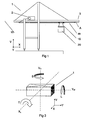
- FIG 1 shows a simplified schematic diagram of a ship-to-shore (STS) crane 1 arranged on a quayside for loading or unloading containers from a ship.
- the motor house mounted on the boom of the crane is arranged with main lifting motors and winding drums 2 which reel in or reel out ropes or load lines for lifting or lowering a container 20.
- the main lifting action takes place between the sheaves nearest the motor house and the boom tip 3 indicated as one end of the boom.
- Container 20 is held by a spreader 15 suspended from a trolley 21 which moves in the direction of arrow X forward (+ve) and back (-ve) along the boom.
- the load lines arranged on trolley 21 are also connected to actuators A (16-19) arranged at or near the tip 3 of the boom.
- the actuators, spreader, trolley and load lines are shown in more detail in Figure 2 .
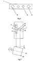
- FIG 2 shows an arrangement according to an embodiment of the invention.
- the figure shows the container 20 held by a spreader 15 suspended from a trolley 21.
- the container is lifted and lowered by main winding drums 2, housed in the motor house ( Fig 1 ).
- the load lines are arranged with actuators 16-19 which lengthen or shorten the load lines at that point.
- the spreader 15 is suspended from the trolley by load lines arranged at four points generally corresponding with the corners of the spreader 4a-4d.
- Trolley 21 is arranged with a sensor 5, preferably a CCD camera, which is aimed down at an optical target 7, which comprises two or more targets 8, 9 which preferably are light sources.
- Figure 3 shows three principal orthogonal axes with respect to a container 20, and shows three imaginary centre lines for the container with respect to the orthogonal axes.
- the figure also shows diagrammatically a skew error S as a rotation about a vertical axis V H , a list error L with which a container tends to list around its long axis and rotate about the axis Y W , and a trim error T with which one of the ends of the container along the long axis hangs lower, shown as a rotation about the imaginary centre line axis X L .
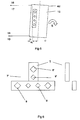
- Figure 4 shows a light source 7.
- This comprises at least two light sources, which are preferably arranged as two large light sources 8, and two smaller sources 9.
- Measurements of two smaller light sources may be discarded when the spreader is very low, ie is at a great distance from the trolley.
- measurements of two larger light sources may be discarded when the spreader is close to the trolley (when the spreader is high).
- the load control equipment consists of one CCD camera 5 and at least two of a plurality of optical transmitters 8, and/or 9.
- Optical transmitters 8 and 9 are of different size or light intensity.
- the CCD camera 5 is mounted under the boom preferably on the trolley, and the optical targets are mounted on the spreader.
- an optical target (comprising at least two optical targets) aligned with the spreader moves as the container moves, and is arranged in a clear line of sight from camera 5. Measurements from camera 5 are taken continuously and distances calculated between the trolley and the spreader.
- the spreader has a skew error and is rotated around its vertical axis V in the direction S of Figures 2 , 3 , then the spreader is positioned at an angle to orthogonal direction Y which, in concrete terms, means that at least one corner 4a-4d of the container has a distance error and is positioned too far from the boom tip and at least one other corner has a position error and is to close to the boom tip.
- one or more actuators 16-19 are controlled so as to drive a load line, and thus a corner of the spreader 4a-4d, towards or away from the boom tip.
- actuator 18 can reel out a load line and 19 reel in to move corner 4a nearer to the tip of the boom.
- 16 could be reeled out and 17 reeled in to move corner 4c further away from the boom tip.
- the load line is reeled in by one actuator and reeled out by the other actuator by the same amount, same distance, to correct a linear error due to skew.
- the distance from the trolley to each of the optical targets on the spreader is measured, and the position of the optical targets relative an orthogonal axis is measured, so that one or more linear errors of position in an X or Y direction are calculated.
- a linear error such as a skew-type error
- the actuators are moved a calculated distance in a linear direction to lengthen and/or shorten load lines arranged at one or more corners 4a-4d of the spreader. In this way the spreader is directly moved in a chosen linear direction by a measured amount by controlling the actuators, in order to minimize a measured or a measured and calculated linear error of spreader position.
- a continuous measurement means on one or more actuators is used to determine the position of each actuator at all times.
- An optical absolute encoder is preferred, such as the type in which the measuring system consists of a light source, a code disc mounted in a precision bearing and an opto-electronic scanning device.
- a light source preferably an LED, illuminates the code disc and projects a pattern known as a track on the code disk onto the opto-array. At every position as the code disk rotates disk the opto-electronic array is partially covered by the dark track markings on the code disk. The light source transmitted through the code disk is interrupted and the code on the disc is transformed in the opto array into electronic signals.
- a multi-turn encoder may be used because more than one turn of the actuator shaft may be expected during an adjustment of the length of the load rope or load line.
- a multi-turn encoder may comprise several single turn encoders coupled together using a means such as a reduction gear.
- Figure 8 shows a flowchart or block diagram describing the steps that a computer program may execute in order to make a computer or processor carry out a method for load control according to an embodiment of the invention.
- Distance from the trolley to the spreader is measured 70, preferably continuously.
- a linear deviation is calculated. If the linear deviation is determined to be a skew error, e s then the present positions of the actuators is checked and at least one pair of actuators, such as 18 and 19, or 17 and 16, is move 78. Which is to say that in the case or a rotated error, a skew error, one actuator of each pair reels out and the other one reels in.
- a list error for a container is corrected by application of each actuator pair parallel with the same long side moving (reeling out or reeling in) in the same direction: Pair Pair List error 18, 16 19, 17 Error direction Reel in Reel out + Reel out Reel in -
- a trim error is remedied by applying each actuator pair corresponding to each short side moving (reeling out or reeling in) in the same direction: Pair Pair Trim error 17, 16 18, 19 Error direction Reel in Reel out + Reel out Reel in -
- Figure 7 shows a list error, in which one side of the container is rotated below the centre line by a linear distance of e L
- the corrections for errors of any of a skew, trim or list type may be applied together of subsequently.
- the trim or list correction is applied at a slower rate, using a lesser signal amplification in a proportional P-type loop.
- Figure 9 and Figure 10 each show a similar flowchart for a computer program to control as that shown in Figure 8 , for skew correction.
- Figure 9 for correcting a trim error specifies in contrast to the skew method shown in Figure 8 that the at least two actuators corresponding to the same long side of a spreader, eg 4a-4c or 4b-4d, both of them move in the same direction, +ve or -ve.
- the skew correction method mapped in Figure 8 points out that actuators move in opposition, ie one +ve and the other of the pair -ve.
- Figure 10 shows a flowchart for correcting a list error.
- the actuator pairs also move in the same direction, in this case each pair corresponding to the short sides, ie 4a-4b and/or 4c-4d.
- At least one camera member is a CCD camera.
- other optical instruments may also be used, such as a laser scanner or laser range finder.
- at least one optical target is an Infra Red (IR) transmitter.
- IR Infra Red
- other optical targets may be provided, such as: LCD diodes, fluorescent lamps or reflective targets such as reflectors, markings, patterns or high contrast surfaces on the spreader.
- the light source 7 comprises optical targets arranged in two directions.
- a T-shaped or even cross shaped arrangement of light sources may be used.
- one part of the arrangement, such as 7' of Figure 4 , 6 has a part T arranged at a different height to the main linear part, as shown by the side elevation elements of Figure 6 .
- the difference in height between the main light sources and the light sources of the T part enable the CCD camera scanning to measure the list error more accurately because the vertical distance between the first light sources and the light sources of the T shape are already known.
- an incremental encoder may be used as a simpler and cheaper sensor for finding actuator position.
- an incremental encoder or a combination of incremental encoders are used in situations where re-starts or re-configurations due, for example, to unexpected power loss or error situations are extremely rare.
- One or more microprocessors comprise a central processing unit CPU performing the steps of the methods according to one or more aspects of the invention, as described for example with reference to Figures 3-7 .
- the comparator may be comprised as a processor, or it may be comprised as a standard computer or processor or other device or a dedicated analogue or digital device or on one or more specially adapted computers or processors, FPGAs (field programmable gate arrays) or ASICs (application specific integrated circuits) or other devices such as simple programmable logic devices (SPLDs), complex programmable logic devices (CPLDs), field programmable system chips (FPSCs).
- SPLDs simple programmable logic devices
- CPLDs complex programmable logic devices
- FPSCs field programmable system chips
- the computer program comprises computer program code elements or software code portions that make the computer, processor or other device perform the methods using equations, algorithms, recursive algorithms, wireless communications parameter data, stored values, calculations and statistical or pattern recognition methods previously described, for example in relation to Figures 1 and Figs 8-10 .
- a part of the program may be stored in a processor, but also or instead in a ROM, RAM, PROM, EPROM or EEPROM chip or similar memory means.
- the program in part or in whole may also be stored locally (or centrally) on, or in, other suitable computer readable medium such as a magnetic disk, CD-ROM or DVD disk, hard disk, magneto-optical memory storage means, in volatile memory, in flash memory, as firmware, or stored on a data server.
- Other known and suitable media including removable memory media such as Sony memory stick (TM) and other removable flash memories, hard drives etc. may also be used.
- the program may also in part be supplied from a data network, including a public network such as the Internet.
- the computer programs described may also be arranged in part as a distributed application capable of running on several different computers or computer systems at more or less the same time.
- a graphical user interface may be used to display one or more of the values obtained using the device and methods described above during the calculation of the position of the load of the crane.
- GUI graphical user interface
- one or more readouts of parameters for the present container load such as speed in an X (or Y) horizontal direction, speed in a vertical direction are displayed on a screen in numerical and/or graphical representations.
- one or more such GUIs may be used to display relative positions of crane 1, load 15 and landing or lifting target relative to a real or graphical representation of the crane, load, landing position, truck etc in a part of a freight yard or container port.
- a selection action such as right-click with a computer mouse, or other computer input/selection member, on parts of the representation of the GUI may result in a display of any of: live real-time values for displacement errors of trim, list or skew type, or list or trim or visual representation of container orientation; stored values for errors in load position; configuration screens where it is possible to set or change predetermined values used in the determination of a position error, determination of a skew or list or trim error, calculation of load position.
- one or more parts of the GUI may be combined on a screen together with a display of part of the operations provided by a video camera.
- one or more parts of the GUI may be provided to give a visual readout which is superimposed over live pictures of the lifting or landing operations.
- one or more graphical and/or numerical values for load position, trim error, list or skew error etc. may be superimposed on a live video picture while the load is being handled.
Landscapes
- Engineering & Computer Science (AREA)
- Mechanical Engineering (AREA)
- Automation & Control Theory (AREA)
- Control And Safety Of Cranes (AREA)
- Load-Engaging Elements For Cranes (AREA)
Claims (33)
- Dispositif de commande de charge pour commander un déplacement d'une charge suspendue d'une grue de conteneur, la grue comprenant un chariot (21) transporteur, un cadre (15) de préhension et des lignes de charge montées suivant une suspension (4a à 4d) à quatre points pour soulever une charge et un capteur (5) optique pour détecter une position de déviation d'un axe (X, Y, V) orthogonal d'un conteneur suspendu sous le cadre de préhension par rapport à une ligne (XL, YW, VH) de centre imaginaire de l'axe orthogonal du conteneur, dans lequel deux actionneurs (16 à 19) ou plus sont adjoints à au moins une ligne de charge et sont agencés pour déplacer au moins un point (4a-d) de suspension en le rapprochant ou en l'éloignant de la ligne (XL, YW, VH) de centre imaginaire en raccourcissant et/ou en allongeant la au moins une ligne de charge, et un moyen à capteur est monté sur au moins un actionneur pour détecter la position de l'actionneur et ainsi tout changement de longueur de la au moins une ligne de charge, caractérisé en ce que le capteur optique est monté dans la visibilité directe de deux ou plusieurs sources (7) lumineuses montées sur le cadre de préhension suivant une première ligne droite par rapport à un axe orthogonal du conteneur, en ce que le capteur optique est monté aussi dans la visibilité directe d'au moins une troisième source (T) lumineuse montée sur le cadre de préhension sur une ligne qui est perpendiculaire à la première ligne droite et en ce que la au moins une troisième source (T) lumineuse est montée sur le cadre de préhension à une distance verticale des sources (7) lumineuses de la première ligne droite.
- Dispositif suivant la revendication 1, dans lequel au moins un premier actionneur (16, 18) est agencé pour enrouler une première partie d'une première ligne de charge et en même temps au moins un deuxième actionneur (17, 19) est agencé pour relâcher une deuxième partie d'une première ligne de charge.
- Dispositif suivant la revendication 1, dans lequel au moins un actionneur comprend un dispositif agencé pour se déplacer dans un sens vers l'avant ou en sens contraire pour enrouler ou relâcher une partie d'une ligne de charge.
- Dispositif suivant la revendication 3, dans lequel au moins un actionneur comprend un dispositif agencé pour un déplacement en ligne droite vers l'avant ou en sens contraire.
- Dispositif suivant la revendication 1, dans lequel au moins un actionneur comprend un entraînement par vis, actionné par un moteur, pour déplacer une ligne de charge sensiblement en ligne droite.
- Dispositif suivant la revendication 5, ayant au moins un actionneur qui comprend un dispositif à vis, agencé pour déployer ou retirer un arbre.
- Dispositif suivant la revendication 1, qui comprend des moyens de comparaison d'une première position d'actionneur et de limites de déplacement à une deuxième position d'actionneur et de limites de déplacement et pour déterminer l'actionneur qui doit être déplacé.
- Dispositif suivant la revendication 1, qui comprend une unité de commande ayant une boucle de commande pour ajuster une erreur de déviation détectée à une référence donnée, en utilisant une boucle comprenant une entrée en provenance d'une position détectée d'au moins un actionneur (16 à 19).
- Dispositif suivant la revendication 8, dans lequel l'unité de commande comprend une entrée d'une valeur continue d'une position d'au moins un actionneur.
- Dispositif suivant la revendication 8, dans lequel l'unité de commande comprend une entrée d'une valeur d'une position d'actionneur échantillonnée par rapport à un laps de temps ou à un incrément de déplacement.
- Dispositif suivant la revendication 1, dans lequel le dispositif de commande de charge comprend quatre actionneurs montés du même côté du cadre de préhension.
- Dispositif suivant la revendication 1, dans lequel le dispositif de commande de charge comprend quatre actionneurs montés du côté de la pointe de flèche d'un cadre de préhension.
- Dispositif suivant la revendication 1, dans lequel le dispositif de commande de charge comprend au moins un moteur électrique tournant, monté comme moyen d'entraînement d'au moins un actionneur pour allonger ou raccourcir une ligne de charge.
- Dispositif suivant la revendication 1, dans lequel au moins un actionneur est actionné par un moteur et comprend une transmission pour déplacer une ligne de charge choisie parmi l'un de la liste de : vis sans fin, commande par engrenage conique, mécanisme à crémaillère.
- Dispositif suivant la revendication 1, dans lequel un ou plusieurs dispositifs actionnés hydrauliquement sont montés comme moyen d'entraînement ou comme actionneur pour déplacer une ligne de charge et ainsi allonger ou raccourcir la ligne de charge.
- Dispositif suivant la revendication 1, dans lequel le capteur (5) optique est l'un parmi la liste de caméra CCD, d'explorateur laser, de télémètre laser.
- Procédé de commande d'une grue de conteneur ayant une charge suspendue au moyen d'un dispositif de commande de charge, la grue comprenant un chariot transporteur, un cadre de préhension et des lignes de charge montées suivant une suspension à quatre points pour soulever une charge et un capteur optique monté sur le chariot transporteur, dans lequel :- on détecte par le capteur optique une position de déviation d'un axe (X, Y, V) orthogonal d'un conteneur (1) (ou d'un cadre de préhension) par rapport à une ligne (XL, YW, VH) de centre imaginaire de cet axe orthogonal, on détecte optiquement une déviation, le capteur optique étant monté dans la visibilité directe de deux ou de plusieurs sources (7) lumineuses, montées sur le cadre de préhension suivant une première ligne droite par rapport à l'axe orthogonal du conteneur, le capteur optique étant monté aussi dans la visibilité directe d'au moins une troisième source (T) lumineuse, montée sur le cadre de préhension sur une ligne qui est perpendiculaire à la première ligne droite et la au moins une troisième source (T) lumineuse est montée sur le cadre de préhension à une distance verticale des sources (7) lumineuses de la première ligne droite,- on détermine une position linéaire d'au moins un actionneur, et on envoie un signal au au moins deux actionneurs pour rapprocher au moins un point (4a-d) de suspension de la ligne (XL, YW, VH) de centre imaginaire ou pour l'en éloigner.
- Procédé suivant la revendication 17, dans lequel en outre on compare une première position d'actionneur et de limites de mouvement d'actionneur à au moins une deuxième position d'actionneur et de limites de déplacement et on détermine celui de l'actionneur ou des actionneurs qui sera à déplacer.
- Procédé suivant la revendication 17, dans lequel en outre on enroule une première partie d'une première ligne de charge et en même temps on relâche une deuxième partie de la première ligne de charge et ainsi on raccourcit ou on allonge une partie de la première ligne de charge.
- Procédé suivant la revendication 19, comprenant en outre le stade suivant lesquels deux actionneurs d'une paire d'actionneurs correspondant à un même côté du cadre de préhension enroulent dans le même sens positif ou négatif.
- Procédé suivant la revendication 20, comprenant en outre le stade suivant lequel deux actionneurs d'une paire d'actionneurs, correspondant au même côté du cadre de préhension, relâchent une ligne de charge à la fois dans le même sens positif ou négatif.
- Procédé suivant la revendication 17, comprenant en outre le stade dans lequel on entraîne au moins un actionneur par un moteur pourvu d'un dispositif à vis.
- Procédé suivant la revendication 22, comprenant en outre le stade dans lequel on entraîne au moins un actionneur par un moteur muni d'un dispositif à vis pour déployer, retirer un arbre adjoint à une ligne de charge.
- Procédé suivant la revendication 17, comprenant en outre le stade dans lequel on détermine continuellement une position d'au moins un actionneur.
- Procédé suivant la revendication 17, comprenant en outre le stade dans lequel on détermine une position d'au moins un actionneur au moyen d'échantillons en fonction d'un laps de temps ou d'un incrément de déplacement.
- Procédé suivant la revendication 17, comprenant en outre le stade dans lequel on mesure par le capteur optique une distance à deux ou plusieurs sources lumineuses, montées sur le cadre de préhension suivant une première ligne droite, par rapport à l'axe orthogonal du conteneur.
- Procédé suivant la revendication 17, comprenant en outre le stade dans lequel on mesure par le capteur optique une distance à deux ou plusieurs sources lumineuses, montées suivant les premières lignes droites sur le cadre de préhension et on mesure toute déviation linéaire par rapport à l'axe orthogonal dans une direction X ou Y.
- Procédé suivant la revendication 27, comprenant en outre le stade dans lequel on mesure par le capteur optique une distance à au moins une troisième source (T) lumineuse, montée sur une ligne perpendiculaire à la première ligne droite et on détermine une erreur d'inclinaison.
- Procédé suivant la revendication 28, comprenant en outre le stade dans lequel on détermine une distance à la au moins une troisième source lumineuse, on calcule une déviation d'inclinaison du conteneur et on détermine un mouvement commun d'une paire d'un ou de plusieurs des points (4a-4c, 4b-4d) de suspension pour corriger l'erreur d'inclinaison.
- Procédé suivant la revendication 17, comprenant en outre le stade dans lequel on mesure une distance du capteur optique à chacune des sources lumineuses, on mesure une déviation linéaire, une erreur d'assiette du cadre de préhension et on détermine un mouvement commun d'une paire d'un ou de plusieurs des points (4a-4b, 4c-4d) de suspension pour corriger l'erreur d'assiette.
- Procédé suivant l'une quelconque des revendications 17 à 30, dans lequel, en outre, on commande la grue de conteneur en faisant passer un ou plusieurs programmes d'ordinateur dans au moins un ordinateur ou un processeur.
- Programme d'ordinateur qui, lorsqu'il est exploité dans un ordinateur ou dans un processeur, fera que l'ordinateur ou le processeur effectue un procédé suivant les stades de l'une quelconque des revendications 17 à 30.
- Support pouvant être exploité par un ordinateur et comprenant un programme d'ordinateur qui, lorsqu'il est exploité dans un ordinateur ou dans un processeur, fera que l'ordinateur ou le processeur effectuera un procédé suivant les stades de l'une quelconque des revendications 17 à 30.
Applications Claiming Priority (1)
| Application Number | Priority Date | Filing Date | Title |
|---|---|---|---|
| US11/511,502 US7950539B2 (en) | 2005-06-28 | 2006-08-29 | Load control device for a crane |
Publications (3)
| Publication Number | Publication Date |
|---|---|
| EP1894881A2 EP1894881A2 (fr) | 2008-03-05 |
| EP1894881A3 EP1894881A3 (fr) | 2011-11-30 |
| EP1894881B1 true EP1894881B1 (fr) | 2013-01-02 |
Family
ID=38871585
Family Applications (1)
| Application Number | Title | Priority Date | Filing Date |
|---|---|---|---|
| EP20060120670 Active EP1894881B1 (fr) | 2006-08-29 | 2006-09-14 | Dispositif de controle de charge pour une grue |
Country Status (2)
| Country | Link |
|---|---|
| EP (1) | EP1894881B1 (fr) |
| ES (1) | ES2401439T3 (fr) |
Families Citing this family (14)
| Publication number | Priority date | Publication date | Assignee | Title |
|---|---|---|---|---|
| SE530490C2 (sv) * | 2006-12-21 | 2008-06-24 | Abb Ab | Kalibreringsanordning, metod och system för en containerkran |
| RU2406679C2 (ru) * | 2009-02-20 | 2010-12-20 | Общество с ограниченной ответственностью "Научно-производственное предприятие "Резонанс" | Способ предотвращения раскачивания груза на гибком подвесе (варианты) |
| WO2012161584A1 (fr) | 2011-05-20 | 2012-11-29 | Optilift As | Système, dispositif et procédé pour suivre position et orientation de véhicule, dispositif de chargement et chargement dans opérations de dispositif de chargement |
| FI125644B (fi) * | 2011-07-18 | 2015-12-31 | Konecranes Oyj | Järjestelmä ja menetelmä nosturin tartuntaelimen sijainnin ja kiertymän määrittämiseksi |
| DE102012213604A1 (de) * | 2012-08-01 | 2014-02-06 | Ge Energy Power Conversion Gmbh | Verladevorrichtung für Container sowie Verfahren zu deren Betrieb |
| WO2014039009A1 (fr) * | 2012-09-05 | 2014-03-13 | Nsl Engineering Pte Ltd | Système de transport de conteneurs |
| FI125689B (fi) * | 2012-10-02 | 2016-01-15 | Konecranes Global Oy | Kuorman käsitteleminen kuormankäsittelylaitteella |
| CN106477457A (zh) * | 2015-09-01 | 2017-03-08 | 张紫勇 | 集装箱桥吊吊具智能安全着箱装置 |
| CN105858487B (zh) * | 2016-04-22 | 2018-01-02 | 荣建生 | 一种双小车异向移动桥架型起重机 |
| AT520008B1 (de) * | 2017-05-29 | 2020-02-15 | B & R Ind Automation Gmbh | Verfahren zum Dämpfen von Drehschwingungen eines Lastaufnahmeelements einer Hebeeinrichtung |
| JP7069888B2 (ja) | 2018-03-15 | 2022-05-18 | 株式会社タダノ | クレーンおよびクレーンの制御方法 |
| NL2021143B1 (nl) * | 2018-06-18 | 2020-01-06 | Stinis Beheer Bv | Werkwijze en inrichting voor het richten van een last die door hijskabels aan een kraan opgehangen is |
| CN111055855B (zh) * | 2019-12-31 | 2021-02-26 | 中车长江车辆有限公司 | 升降式车架以及空中运输车辆 |
| CN111924712A (zh) * | 2020-08-10 | 2020-11-13 | 郑州中粮科研设计院有限公司 | 基于视觉定位的散粮集装箱装卸装置 |
Family Cites Families (7)
| Publication number | Priority date | Publication date | Assignee | Title |
|---|---|---|---|---|
| AU471953B2 (en) * | 1972-12-29 | 1976-05-06 | Ishikawajima-Harima Jukogyo K.K. | Device for preventing the swaying ofthe suspending means ina crane |
| SE502609C2 (sv) * | 1990-03-28 | 1995-11-20 | Asea Brown Boveri | Förflyttning av gods med containerkranar |
| DE4219370A1 (de) * | 1992-06-13 | 1993-12-16 | Krupp Industrietech | Hubeinrichtung für Lasten |
| DE4325946C2 (de) * | 1993-08-02 | 1998-04-09 | Fraunhofer Ges Forschung | Dämpfungs- und Positioniereinrichtung zur aktiven Dämpfung der Pendelung von an Kranen aufgehängten Lasten |
| FI104816B (fi) * | 1997-09-24 | 2000-04-14 | Kci Kone Cranes Int Oy | Laite nosturin nostoköysistöön kohdistuvan ylikuormituksen ja törmäysliike-energian vaimentamiseksi |
| JP2003267660A (ja) * | 2002-03-19 | 2003-09-25 | Mitsui Eng & Shipbuild Co Ltd | ガントリークレーンのコンテナ位置決め装置 |
| DE10245970B4 (de) * | 2002-09-30 | 2008-08-21 | Siemens Ag | Verfahren bzw. Vorrichtung zur Erkennung einer Last eines Hebezeuges |
-
2006
- 2006-09-14 EP EP20060120670 patent/EP1894881B1/fr active Active
- 2006-09-14 ES ES06120670T patent/ES2401439T3/es active Active
Also Published As
| Publication number | Publication date |
|---|---|
| ES2401439T3 (es) | 2013-04-19 |
| EP1894881A3 (fr) | 2011-11-30 |
| EP1894881A2 (fr) | 2008-03-05 |
Similar Documents
| Publication | Publication Date | Title |
|---|---|---|
| US7950539B2 (en) | Load control device for a crane | |
| CN104860203B (zh) | 对集装箱转运起重机上的激光扫描仪校准的方法 | |
| EP1894881A2 (fr) | Dispositif de controle de charge pour une grue | |
| US7289876B2 (en) | Container crane, and method of determining and correcting a misalignment between a load-carrying frame and a transport vehicle | |
| CN103781717B (zh) | 确定起重机的抓取构件的位置和偏斜度的系统和方法 | |
| US8025167B2 (en) | Crane control, crane and method | |
| CN105492365B (zh) | 用于通过吊具的货物装卸的方法、装置和套件 | |
| TR201904821T4 (tr) | Yük elleçleme cihazı ile yük elleçlenmesi. | |
| FI130196B (en) | GRIPPER POSITION CONTROL | |
| US6962091B2 (en) | System and method for measuring a horizontal deviation of a load receiving element | |
| CN111302226B (zh) | 基于专家系统的集装箱自动着箱装置及其控制方法 | |
| US20190074204A1 (en) | Overhead transport vehicle system and teaching method for overhead transport vehicle | |
| US6351720B1 (en) | Trolley camera position detecting apparatus | |
| CN113753759B (zh) | 一种吊具定位方法、吊具定位装置及起重设备 | |
| JP6984080B2 (ja) | クレーンの振れ止め制御に用いる振り子長の測定装置 | |
| CN118373330B (zh) | 一种起重机主梁拱度变形智能补偿方法及系统 | |
| JP6807131B2 (ja) | 荷役搬送装置 | |
| JP2004161475A (ja) | 吊荷の積み付け制御方法及び制御装置並びに荷役機械 | |
| CN113247770A (zh) | 吊具角度调节方法、吊具调节机构及门座起重机 | |
| KR20050007241A (ko) | 컨테이너의 자동랜딩을 위한 스프레더의 절대위치검출방법 및 알고리즘 | |
| WO2020184025A1 (fr) | Grue et procédé de chargement avec une grue | |
| WO2019245361A1 (fr) | Procédé et appareil d'orientation d'une charge suspendue sur une grue par des câbles de levage | |
| JPS6118693A (ja) | 長尺物移送用クレーン |
Legal Events
| Date | Code | Title | Description |
|---|---|---|---|
| PUAI | Public reference made under article 153(3) epc to a published international application that has entered the european phase |
Free format text: ORIGINAL CODE: 0009012 |
|
| AK | Designated contracting states |
Kind code of ref document: A2 Designated state(s): AT BE BG CH CY CZ DE DK EE ES FI FR GB GR HU IE IS IT LI LT LU LV MC NL PL PT RO SE SI SK TR |
|
| AX | Request for extension of the european patent |
Extension state: AL BA HR MK YU |
|
| 17P | Request for examination filed |
Effective date: 20080827 |
|
| PUAL | Search report despatched |
Free format text: ORIGINAL CODE: 0009013 |
|
| AK | Designated contracting states |
Kind code of ref document: A3 Designated state(s): AT BE BG CH CY CZ DE DK EE ES FI FR GB GR HU IE IS IT LI LT LU LV MC NL PL PT RO SE SI SK TR |
|
| AX | Request for extension of the european patent |
Extension state: AL BA HR MK RS |
|
| RIC1 | Information provided on ipc code assigned before grant |
Ipc: B66C 13/46 20060101ALI20111027BHEP Ipc: B66C 13/08 20060101AFI20111027BHEP |
|
| RIC1 | Information provided on ipc code assigned before grant |
Ipc: B66C 13/46 20060101ALI20120531BHEP Ipc: B66C 13/08 20060101AFI20120531BHEP Ipc: B66C 1/66 20060101ALI20120531BHEP |
|
| GRAP | Despatch of communication of intention to grant a patent |
Free format text: ORIGINAL CODE: EPIDOSNIGR1 |
|
| AKX | Designation fees paid |
Designated state(s): AT BE BG CH CY CZ DE DK EE ES FI FR GB GR HU IE IS IT LI LT LU LV MC NL PL PT RO SE SI SK TR |
|
| GRAS | Grant fee paid |
Free format text: ORIGINAL CODE: EPIDOSNIGR3 |
|
| GRAA | (expected) grant |
Free format text: ORIGINAL CODE: 0009210 |
|
| AK | Designated contracting states |
Kind code of ref document: B1 Designated state(s): AT BE BG CH CY CZ DE DK EE ES FI FR GB GR HU IE IS IT LI LT LU LV MC NL PL PT RO SE SI SK TR |
|
| REG | Reference to a national code |
Ref country code: GB Ref legal event code: FG4D |
|
| REG | Reference to a national code |
Ref country code: CH Ref legal event code: EP Ref country code: AT Ref legal event code: REF Ref document number: 591495 Country of ref document: AT Kind code of ref document: T Effective date: 20130115 |
|
| REG | Reference to a national code |
Ref country code: IE Ref legal event code: FG4D |
|
| REG | Reference to a national code |
Ref country code: DE Ref legal event code: R096 Ref document number: 602006033924 Country of ref document: DE Effective date: 20130228 |
|
| REG | Reference to a national code |
Ref country code: SE Ref legal event code: TRGR |
|
| REG | Reference to a national code |
Ref country code: ES Ref legal event code: FG2A Ref document number: 2401439 Country of ref document: ES Kind code of ref document: T3 Effective date: 20130419 |
|
| REG | Reference to a national code |
Ref country code: NL Ref legal event code: T3 |
|
| REG | Reference to a national code |
Ref country code: AT Ref legal event code: MK05 Ref document number: 591495 Country of ref document: AT Kind code of ref document: T Effective date: 20130102 |
|
| PG25 | Lapsed in a contracting state [announced via postgrant information from national office to epo] |
Ref country code: SI Free format text: LAPSE BECAUSE OF FAILURE TO SUBMIT A TRANSLATION OF THE DESCRIPTION OR TO PAY THE FEE WITHIN THE PRESCRIBED TIME-LIMIT Effective date: 20130102 |
|
| REG | Reference to a national code |
Ref country code: LT Ref legal event code: MG4D |
|
| PG25 | Lapsed in a contracting state [announced via postgrant information from national office to epo] |
Ref country code: AT Free format text: LAPSE BECAUSE OF FAILURE TO SUBMIT A TRANSLATION OF THE DESCRIPTION OR TO PAY THE FEE WITHIN THE PRESCRIBED TIME-LIMIT Effective date: 20130102 Ref country code: BG Free format text: LAPSE BECAUSE OF FAILURE TO SUBMIT A TRANSLATION OF THE DESCRIPTION OR TO PAY THE FEE WITHIN THE PRESCRIBED TIME-LIMIT Effective date: 20130402 Ref country code: CZ Free format text: LAPSE BECAUSE OF FAILURE TO SUBMIT A TRANSLATION OF THE DESCRIPTION OR TO PAY THE FEE WITHIN THE PRESCRIBED TIME-LIMIT Effective date: 20130102 Ref country code: BE Free format text: LAPSE BECAUSE OF FAILURE TO SUBMIT A TRANSLATION OF THE DESCRIPTION OR TO PAY THE FEE WITHIN THE PRESCRIBED TIME-LIMIT Effective date: 20130102 Ref country code: IS Free format text: LAPSE BECAUSE OF FAILURE TO SUBMIT A TRANSLATION OF THE DESCRIPTION OR TO PAY THE FEE WITHIN THE PRESCRIBED TIME-LIMIT Effective date: 20130502 Ref country code: LT Free format text: LAPSE BECAUSE OF FAILURE TO SUBMIT A TRANSLATION OF THE DESCRIPTION OR TO PAY THE FEE WITHIN THE PRESCRIBED TIME-LIMIT Effective date: 20130102 |
|
| PG25 | Lapsed in a contracting state [announced via postgrant information from national office to epo] |
Ref country code: PL Free format text: LAPSE BECAUSE OF FAILURE TO SUBMIT A TRANSLATION OF THE DESCRIPTION OR TO PAY THE FEE WITHIN THE PRESCRIBED TIME-LIMIT Effective date: 20130102 Ref country code: LV Free format text: LAPSE BECAUSE OF FAILURE TO SUBMIT A TRANSLATION OF THE DESCRIPTION OR TO PAY THE FEE WITHIN THE PRESCRIBED TIME-LIMIT Effective date: 20130102 Ref country code: GR Free format text: LAPSE BECAUSE OF FAILURE TO SUBMIT A TRANSLATION OF THE DESCRIPTION OR TO PAY THE FEE WITHIN THE PRESCRIBED TIME-LIMIT Effective date: 20130403 Ref country code: PT Free format text: LAPSE BECAUSE OF FAILURE TO SUBMIT A TRANSLATION OF THE DESCRIPTION OR TO PAY THE FEE WITHIN THE PRESCRIBED TIME-LIMIT Effective date: 20130502 |
|
| PG25 | Lapsed in a contracting state [announced via postgrant information from national office to epo] |
Ref country code: DK Free format text: LAPSE BECAUSE OF FAILURE TO SUBMIT A TRANSLATION OF THE DESCRIPTION OR TO PAY THE FEE WITHIN THE PRESCRIBED TIME-LIMIT Effective date: 20130102 Ref country code: RO Free format text: LAPSE BECAUSE OF FAILURE TO SUBMIT A TRANSLATION OF THE DESCRIPTION OR TO PAY THE FEE WITHIN THE PRESCRIBED TIME-LIMIT Effective date: 20130102 Ref country code: SK Free format text: LAPSE BECAUSE OF FAILURE TO SUBMIT A TRANSLATION OF THE DESCRIPTION OR TO PAY THE FEE WITHIN THE PRESCRIBED TIME-LIMIT Effective date: 20130102 Ref country code: EE Free format text: LAPSE BECAUSE OF FAILURE TO SUBMIT A TRANSLATION OF THE DESCRIPTION OR TO PAY THE FEE WITHIN THE PRESCRIBED TIME-LIMIT Effective date: 20130102 |
|
| PLBE | No opposition filed within time limit |
Free format text: ORIGINAL CODE: 0009261 |
|
| STAA | Information on the status of an ep patent application or granted ep patent |
Free format text: STATUS: NO OPPOSITION FILED WITHIN TIME LIMIT |
|
| PG25 | Lapsed in a contracting state [announced via postgrant information from national office to epo] |
Ref country code: CY Free format text: LAPSE BECAUSE OF FAILURE TO SUBMIT A TRANSLATION OF THE DESCRIPTION OR TO PAY THE FEE WITHIN THE PRESCRIBED TIME-LIMIT Effective date: 20130102 |
|
| 26N | No opposition filed |
Effective date: 20131003 |
|
| REG | Reference to a national code |
Ref country code: DE Ref legal event code: R097 Ref document number: 602006033924 Country of ref document: DE Effective date: 20131003 |
|
| PG25 | Lapsed in a contracting state [announced via postgrant information from national office to epo] |
Ref country code: MC Free format text: LAPSE BECAUSE OF FAILURE TO SUBMIT A TRANSLATION OF THE DESCRIPTION OR TO PAY THE FEE WITHIN THE PRESCRIBED TIME-LIMIT Effective date: 20130102 |
|
| REG | Reference to a national code |
Ref country code: CH Ref legal event code: PL |
|
| REG | Reference to a national code |
Ref country code: FR Ref legal event code: ST Effective date: 20140530 |
|
| REG | Reference to a national code |
Ref country code: IE Ref legal event code: MM4A |
|
| PG25 | Lapsed in a contracting state [announced via postgrant information from national office to epo] |
Ref country code: IE Free format text: LAPSE BECAUSE OF NON-PAYMENT OF DUE FEES Effective date: 20130914 Ref country code: CH Free format text: LAPSE BECAUSE OF NON-PAYMENT OF DUE FEES Effective date: 20130930 Ref country code: LI Free format text: LAPSE BECAUSE OF NON-PAYMENT OF DUE FEES Effective date: 20130930 |
|
| PG25 | Lapsed in a contracting state [announced via postgrant information from national office to epo] |
Ref country code: FR Free format text: LAPSE BECAUSE OF NON-PAYMENT OF DUE FEES Effective date: 20130930 |
|
| PG25 | Lapsed in a contracting state [announced via postgrant information from national office to epo] |
Ref country code: TR Free format text: LAPSE BECAUSE OF FAILURE TO SUBMIT A TRANSLATION OF THE DESCRIPTION OR TO PAY THE FEE WITHIN THE PRESCRIBED TIME-LIMIT Effective date: 20130102 |
|
| PG25 | Lapsed in a contracting state [announced via postgrant information from national office to epo] |
Ref country code: HU Free format text: LAPSE BECAUSE OF FAILURE TO SUBMIT A TRANSLATION OF THE DESCRIPTION OR TO PAY THE FEE WITHIN THE PRESCRIBED TIME-LIMIT; INVALID AB INITIO Effective date: 20060914 Ref country code: LU Free format text: LAPSE BECAUSE OF NON-PAYMENT OF DUE FEES Effective date: 20130914 |
|
| PGFP | Annual fee paid to national office [announced via postgrant information from national office to epo] |
Ref country code: ES Payment date: 20150928 Year of fee payment: 10 Ref country code: GB Payment date: 20150917 Year of fee payment: 10 |
|
| PGFP | Annual fee paid to national office [announced via postgrant information from national office to epo] |
Ref country code: SE Payment date: 20150923 Year of fee payment: 10 |
|
| PGFP | Annual fee paid to national office [announced via postgrant information from national office to epo] |
Ref country code: IT Payment date: 20150924 Year of fee payment: 10 |
|
| PG25 | Lapsed in a contracting state [announced via postgrant information from national office to epo] |
Ref country code: SE Free format text: LAPSE BECAUSE OF NON-PAYMENT OF DUE FEES Effective date: 20160915 |
|
| REG | Reference to a national code |
Ref country code: SE Ref legal event code: EUG |
|
| GBPC | Gb: european patent ceased through non-payment of renewal fee |
Effective date: 20160914 |
|
| PG25 | Lapsed in a contracting state [announced via postgrant information from national office to epo] |
Ref country code: GB Free format text: LAPSE BECAUSE OF NON-PAYMENT OF DUE FEES Effective date: 20160914 |
|
| PG25 | Lapsed in a contracting state [announced via postgrant information from national office to epo] |
Ref country code: IT Free format text: LAPSE BECAUSE OF NON-PAYMENT OF DUE FEES Effective date: 20160914 |
|
| REG | Reference to a national code |
Ref country code: DE Ref legal event code: R081 Ref document number: 602006033924 Country of ref document: DE Owner name: ABB SCHWEIZ AG, CH Free format text: FORMER OWNER: ABB AB, VAESTERAS, SE |
|
| PG25 | Lapsed in a contracting state [announced via postgrant information from national office to epo] |
Ref country code: ES Free format text: LAPSE BECAUSE OF NON-PAYMENT OF DUE FEES Effective date: 20160915 |
|
| REG | Reference to a national code |
Ref country code: NL Ref legal event code: PD Owner name: ABB SCHWEIZ AG; CH Free format text: DETAILS ASSIGNMENT: CHANGE OF OWNER(S), ASSIGNMENT; FORMER OWNER NAME: ABB AB Effective date: 20180416 |
|
| REG | Reference to a national code |
Ref country code: ES Ref legal event code: FD2A Effective date: 20181129 |
|
| PGFP | Annual fee paid to national office [announced via postgrant information from national office to epo] |
Ref country code: FI Payment date: 20250929 Year of fee payment: 20 |
|
| PGFP | Annual fee paid to national office [announced via postgrant information from national office to epo] |
Ref country code: DE Payment date: 20250919 Year of fee payment: 20 |
|
| PGFP | Annual fee paid to national office [announced via postgrant information from national office to epo] |
Ref country code: NL Payment date: 20250918 Year of fee payment: 20 |