EP1894894A1 - Machine I.S - Google Patents
Machine I.S Download PDFInfo
- Publication number
- EP1894894A1 EP1894894A1 EP07113969A EP07113969A EP1894894A1 EP 1894894 A1 EP1894894 A1 EP 1894894A1 EP 07113969 A EP07113969 A EP 07113969A EP 07113969 A EP07113969 A EP 07113969A EP 1894894 A1 EP1894894 A1 EP 1894894A1
- Authority
- EP
- European Patent Office
- Prior art keywords
- parison
- pressure
- air
- blow
- low pressure
- Prior art date
- Legal status (The legal status is an assumption and is not a legal conclusion. Google has not performed a legal analysis and makes no representation as to the accuracy of the status listed.)
- Granted
Links
Images

Classifications
-
- C—CHEMISTRY; METALLURGY
- C03—GLASS; MINERAL OR SLAG WOOL
- C03B—MANUFACTURE, SHAPING, OR SUPPLEMENTARY PROCESSES
- C03B9/00—Blowing glass; Production of hollow glass articles
- C03B9/30—Details of blowing glass; Use of materials for the moulds
- C03B9/36—Blow heads; Supplying, ejecting or controlling the air
- C03B9/3627—Means for general supply or distribution of the air to the blow heads
-
- C—CHEMISTRY; METALLURGY
- C03—GLASS; MINERAL OR SLAG WOOL
- C03B—MANUFACTURE, SHAPING, OR SUPPLEMENTARY PROCESSES
- C03B9/00—Blowing glass; Production of hollow glass articles
- C03B9/30—Details of blowing glass; Use of materials for the moulds
- C03B9/36—Blow heads; Supplying, ejecting or controlling the air
- C03B9/3663—Details thereof relating to internal blowing of the hollow glass
- C03B9/3672—Details thereof relating to internal blowing of the hollow glass using a tube
Definitions
- the present invention relates to I. S. Machines which transform a gob of molten glass into a glass container such as a bottle.
- a gob of molten glass is delivered to a blank mold in which a "parison" is formed.
- the formed parison includes the "finish", i.e., the threads, etc., of the bottle to be formed which are at the bottom of the vertically standing parison.
- the parison also has an elongated vertical hole which extends upwardly from the finish.
- the finish is gripped by neck ring mold halves or segments carried by a pair of closed neck rings.
- the neck ring is rotated 180 degrees to deliver the parison to the blow station where opposed blow mold halves or segments will be displaced into a clamped closed position about the parison.
- the finish, and hence the parison is supported by the closed blow mold. Reheat then takes place, i.e., the skin of the parison which had been cooled to preserve the shape of the parison, is heated by the inner heat of the parison. When this happens the parison will sag or stretch downwardly by virtue of the parison being suspended from the mold. When the parison stretches to the desired length, either compressed air is introduced into the mold via a blow head sitting on top of the blow mold and/or vacuum is applied through the walls of the blow mold to displace the parison into the form of the mold.
- an I.S. Machine as defined in claim 1, and a method of operating an I.S. Machine as defined in claim 4.
- Each section of an I. S. Machine forms one or more gobs of molten glass into a bottle.
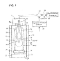
- a blow mold 10 is shown in Figure 1 which is made up of an opposed pair of side molds, halves or segments 12 and a bottom plate 14 which interfits with the side molds when the side molds are fully closed as shown. As shown, the fully closed blow mold sides grip the neck 16 of a parison 18. The finish 20 of the parison is supported by the blow mold.
- the parison which has a long hole 30 extending downwardly from the top, will reheat, i.e., the chilled skin will be heated by the internal heat of the parison, and once reheated the parison will begin to stretch downwardly.
- the parison stretches down to the bottom plate as shown in dotted lines, the parison is blown into a bottle either by applying vacuum to the inside surface of the mold and/or by applying air pressure via the blowhead 32 of a blowhead mechanism which is located on top of the blow mold.
- Coolling air is supplied to vertical holes 22 in the base 24 Tor the bottom plate 14 and these holes communicate with cooling holes 26 extending vertically through the blow mold sides 12.
- cooling air will be forced through these cooling holes to remove heat from the blow mold sides. It is believed that this cooling air bleeds between the bottom surface of the blow mold and the top surface of the base and works its way between the bottom plate and the side molds into the interior of the blow mold and that this leakage expands due to the heat of the parison and acts to crush the parison ultimately causing a birdswing in the formed bottle.
- These pressure forces are illustrated with arrows 28.
- the blow head is shown in place on top of the blow mold with the blow tube 34 extending into the parison.
- the blow head is displaceable between a remote "OFF" position (not shown) and the shown down or “ON” position.
- the blow head is connected to a source of High Pressure Air 35 which is controlled by an on/off valve 36 and a Switchable Pressure Regulating Valve 37 which has a High/Low Pressure Selector 38.
- a source of High Pressure Air 35 which is controlled by an on/off valve 36 and a Switchable Pressure Regulating Valve 37 which has a High/Low Pressure Selector 38.
- FIG. 2 A conventional blow mold open and close mechanism is shown in Figure 2 where a pair of opposed side molds 12 are supported for displacement toward and away from each other. Displacement is via a drive 40 powered by a motor or motors 42. Motion is controlled by a suitable control 44.
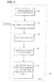
- a control 58 shown in Figure 3 will Displace Blowhead To The "DOWN or ON” Position 60 at the correct time in the cycle (cycle events are initiated by a timing drum which starts every event once each 360 degrees).
- the control will Select Low Pressure 62 and Turn ON/OFF Valve “On” 64.
- Low pressure air will therefore be supplied to the interior of the parison.
- the pressure of this low pressure air (P internal ) is set so that a pressure will be defined within the parison during reheat which will prevent the deformation of the reheating parison as a result of any cavity pressure ( P cavity ) due to cooling air leakage into the space between the parison and the blow mold.
- This pressure will be sufficiently low that it will not blow the parison into a bottle.
- the control will Select High Pressure At End Of Reheat 66 and the parison will be blown by this high pressure into a bottle (the form of the bottle is defined by the interior surface 69 of the blow mold).
- the control will Turn ON/OFF valve "OFF" When Blowhead Is To Be Displaced Away From The “ON” Position 68.
Landscapes
- Engineering & Computer Science (AREA)
- Chemical & Material Sciences (AREA)
- Manufacturing & Machinery (AREA)
- Materials Engineering (AREA)
- Organic Chemistry (AREA)
- Blow-Moulding Or Thermoforming Of Plastics Or The Like (AREA)
- Containers Having Bodies Formed In One Piece (AREA)
Applications Claiming Priority (1)
| Application Number | Priority Date | Filing Date | Title |
|---|---|---|---|
| US11/514,456 US8448472B2 (en) | 2006-09-01 | 2006-09-01 | I. S. machine with pressure control |
Publications (2)
| Publication Number | Publication Date |
|---|---|
| EP1894894A1 true EP1894894A1 (fr) | 2008-03-05 |
| EP1894894B1 EP1894894B1 (fr) | 2013-04-24 |
Family
ID=38441690
Family Applications (1)
| Application Number | Title | Priority Date | Filing Date |
|---|---|---|---|
| EP07113969.5A Not-in-force EP1894894B1 (fr) | 2006-09-01 | 2007-08-07 | Machine I.S |
Country Status (3)
| Country | Link |
|---|---|
| US (1) | US8448472B2 (fr) |
| EP (1) | EP1894894B1 (fr) |
| JP (1) | JP5064937B2 (fr) |
Cited By (1)
| Publication number | Priority date | Publication date | Assignee | Title |
|---|---|---|---|---|
| EP2684850A2 (fr) | 2012-07-14 | 2014-01-15 | Heye International GmbH | Procédé et dispositif de régulation de l'air soufflé et de l'air de refroidissement d'une machine de moulage de verre I.S. |
Families Citing this family (1)
| Publication number | Priority date | Publication date | Assignee | Title |
|---|---|---|---|---|
| JP5073537B2 (ja) | 2008-03-06 | 2012-11-14 | 富士重工業株式会社 | 動力伝達装置 |
Citations (6)
| Publication number | Priority date | Publication date | Assignee | Title |
|---|---|---|---|---|
| US4094656A (en) * | 1977-03-07 | 1978-06-13 | Owens-Illinois, Inc. | Method for forming glass containers |
| US4678492A (en) * | 1985-01-30 | 1987-07-07 | Emhart Industries, Inc. | Blowing process for expanding a molten glass parison |
| GB2297548A (en) * | 1995-01-21 | 1996-08-07 | Emhart Glass Mach Invest | Controlling air supply to glassware blow mould by computer |
| US6401491B1 (en) * | 2000-04-19 | 2002-06-11 | Owens-Brockway Glass Container Inc. | Final blow/finish cooling valve function monitor |
| JP2002356333A (ja) * | 2001-06-04 | 2002-12-13 | Nihon Yamamura Glass Co Ltd | 製びん機の仕上型装置およびこれによるガラスびんの製造方法 |
| US20030101753A1 (en) * | 2001-12-05 | 2003-06-05 | Fenton F. Alan | I.S. glass forming machine |
Family Cites Families (3)
| Publication number | Priority date | Publication date | Assignee | Title |
|---|---|---|---|---|
| US4509969A (en) | 1983-03-04 | 1985-04-09 | Emhart Industries, Inc. | Blowhead apparatus |
| US6240747B1 (en) * | 1997-11-06 | 2001-06-05 | Emhart Glass S.A. | Baffle mechanism for I.S. machine |
| US6269662B1 (en) * | 1999-03-05 | 2001-08-07 | Emhart Glass S.A. | Pneumatic machine control unit for an I.S. machine |
-
2006
- 2006-09-01 US US11/514,456 patent/US8448472B2/en not_active Expired - Fee Related
-
2007
- 2007-08-07 EP EP07113969.5A patent/EP1894894B1/fr not_active Not-in-force
- 2007-08-24 JP JP2007217927A patent/JP5064937B2/ja not_active Expired - Fee Related
Patent Citations (6)
| Publication number | Priority date | Publication date | Assignee | Title |
|---|---|---|---|---|
| US4094656A (en) * | 1977-03-07 | 1978-06-13 | Owens-Illinois, Inc. | Method for forming glass containers |
| US4678492A (en) * | 1985-01-30 | 1987-07-07 | Emhart Industries, Inc. | Blowing process for expanding a molten glass parison |
| GB2297548A (en) * | 1995-01-21 | 1996-08-07 | Emhart Glass Mach Invest | Controlling air supply to glassware blow mould by computer |
| US6401491B1 (en) * | 2000-04-19 | 2002-06-11 | Owens-Brockway Glass Container Inc. | Final blow/finish cooling valve function monitor |
| JP2002356333A (ja) * | 2001-06-04 | 2002-12-13 | Nihon Yamamura Glass Co Ltd | 製びん機の仕上型装置およびこれによるガラスびんの製造方法 |
| US20030101753A1 (en) * | 2001-12-05 | 2003-06-05 | Fenton F. Alan | I.S. glass forming machine |
Cited By (3)
| Publication number | Priority date | Publication date | Assignee | Title |
|---|---|---|---|---|
| EP2684850A2 (fr) | 2012-07-14 | 2014-01-15 | Heye International GmbH | Procédé et dispositif de régulation de l'air soufflé et de l'air de refroidissement d'une machine de moulage de verre I.S. |
| DE102012013840A1 (de) | 2012-07-14 | 2014-01-16 | Heye International Gmbh | Verfahren und Vorrichtung zur Blas- und Kühlluftregelung einer l.S. Glasformmaschine |
| US9458042B2 (en) | 2012-07-14 | 2016-10-04 | Heye International Gmbh | Method and apparatus for controlling the blowing air and cooling air of an I.S. glassware forming machine |
Also Published As
| Publication number | Publication date |
|---|---|
| JP2008056559A (ja) | 2008-03-13 |
| JP5064937B2 (ja) | 2012-10-31 |
| US20080053154A1 (en) | 2008-03-06 |
| US8448472B2 (en) | 2013-05-28 |
| EP1894894B1 (fr) | 2013-04-24 |
Similar Documents
| Publication | Publication Date | Title |
|---|---|---|
| JP7634051B2 (ja) | 樹脂製の容器の製造方法および樹脂製の容器の製造装置 | |
| US2890483A (en) | Machine for forming plastic containers | |
| EP0163618B1 (fr) | Procédé et appareil pour la fabrication d'objets en verre | |
| AU2007201028B8 (en) | Mold cooling system for I.S. machine | |
| US6810690B2 (en) | I.S. glass forming machine | |
| US3403016A (en) | Glassware forming apparatus with blow head control | |
| CA2152939A1 (fr) | Mecanisme plongeur pneumatique pour machine a former des articles en verre | |
| RU2002132624A (ru) | Узел дутьевого формования и способ выдувания бутылки из стеклянной заготовки | |
| US2269553A (en) | Glass machine and method of making glass | |
| EP1894894A1 (fr) | Machine I.S | |
| JP4447954B2 (ja) | I.s.マシーンのための成形型支持機構 | |
| JP3893067B2 (ja) | プリフォームの温調方法 | |
| SU953976A3 (ru) | Способ формовани стекл нной тары | |
| US7975510B2 (en) | I.S. machine | |
| JPH08183623A (ja) | ガラス容器の製造装置 | |
| JPH08109027A (ja) | ガラス容器の製造方法 | |
| US4813995A (en) | Manufacturing containers out of glass | |
| US4525191A (en) | Method of cooling a glass ware mould | |
| JPH0725626A (ja) | プレス・ブロー方式による硝子製品の製造方法及びその製造装置 | |
| US1949899A (en) | Method of and apparatus for making glassware | |
| US4244726A (en) | Apparatus for manufacturing glass bottles | |
| US4293327A (en) | Method for manufacturing glass bottles | |
| US20090078004A1 (en) | Control for I. S. machine | |
| US1737524A (en) | Glass-blowing machine | |
| CN108059323A (zh) | 一种玻璃瓶吹法成型工艺 |
Legal Events
| Date | Code | Title | Description |
|---|---|---|---|
| PUAI | Public reference made under article 153(3) epc to a published international application that has entered the european phase |
Free format text: ORIGINAL CODE: 0009012 |
|
| AK | Designated contracting states |
Kind code of ref document: A1 Designated state(s): AT BE BG CH CY CZ DE DK EE ES FI FR GB GR HU IE IS IT LI LT LU LV MC MT NL PL PT RO SE SI SK TR |
|
| AX | Request for extension of the european patent |
Extension state: AL BA HR MK YU |
|
| 17P | Request for examination filed |
Effective date: 20080327 |
|
| 17Q | First examination report despatched |
Effective date: 20080508 |
|
| AKX | Designation fees paid |
Designated state(s): CZ DE FR GB IT |
|
| GRAP | Despatch of communication of intention to grant a patent |
Free format text: ORIGINAL CODE: EPIDOSNIGR1 |
|
| GRAS | Grant fee paid |
Free format text: ORIGINAL CODE: EPIDOSNIGR3 |
|
| GRAA | (expected) grant |
Free format text: ORIGINAL CODE: 0009210 |
|
| AK | Designated contracting states |
Kind code of ref document: B1 Designated state(s): CZ DE FR GB IT |
|
| REG | Reference to a national code |
Ref country code: GB Ref legal event code: FG4D |
|
| REG | Reference to a national code |
Ref country code: DE Ref legal event code: R096 Ref document number: 602007029953 Country of ref document: DE Effective date: 20130613 |
|
| PLBE | No opposition filed within time limit |
Free format text: ORIGINAL CODE: 0009261 |
|
| STAA | Information on the status of an ep patent application or granted ep patent |
Free format text: STATUS: NO OPPOSITION FILED WITHIN TIME LIMIT |
|
| 26N | No opposition filed |
Effective date: 20140127 |
|
| REG | Reference to a national code |
Ref country code: DE Ref legal event code: R097 Ref document number: 602007029953 Country of ref document: DE Effective date: 20140127 |
|
| REG | Reference to a national code |
Ref country code: FR Ref legal event code: PLFP Year of fee payment: 9 |
|
| PGFP | Annual fee paid to national office [announced via postgrant information from national office to epo] |
Ref country code: GB Payment date: 20150827 Year of fee payment: 9 Ref country code: CZ Payment date: 20150723 Year of fee payment: 9 Ref country code: DE Payment date: 20150827 Year of fee payment: 9 |
|
| PGFP | Annual fee paid to national office [announced via postgrant information from national office to epo] |
Ref country code: FR Payment date: 20150817 Year of fee payment: 9 |
|
| PGFP | Annual fee paid to national office [announced via postgrant information from national office to epo] |
Ref country code: IT Payment date: 20150825 Year of fee payment: 9 |
|
| REG | Reference to a national code |
Ref country code: DE Ref legal event code: R119 Ref document number: 602007029953 Country of ref document: DE |
|
| GBPC | Gb: european patent ceased through non-payment of renewal fee |
Effective date: 20160807 |
|
| REG | Reference to a national code |
Ref country code: FR Ref legal event code: ST Effective date: 20170428 |
|
| PG25 | Lapsed in a contracting state [announced via postgrant information from national office to epo] |
Ref country code: CZ Free format text: LAPSE BECAUSE OF NON-PAYMENT OF DUE FEES Effective date: 20160807 |
|
| PG25 | Lapsed in a contracting state [announced via postgrant information from national office to epo] |
Ref country code: DE Free format text: LAPSE BECAUSE OF NON-PAYMENT OF DUE FEES Effective date: 20170301 Ref country code: GB Free format text: LAPSE BECAUSE OF NON-PAYMENT OF DUE FEES Effective date: 20160807 Ref country code: FR Free format text: LAPSE BECAUSE OF NON-PAYMENT OF DUE FEES Effective date: 20160831 |
|
| PG25 | Lapsed in a contracting state [announced via postgrant information from national office to epo] |
Ref country code: IT Free format text: LAPSE BECAUSE OF NON-PAYMENT OF DUE FEES Effective date: 20160807 |