EP1895761A2 - Appareil de formation d'images électrophotographique et son procédé de correction de tramage - Google Patents
Appareil de formation d'images électrophotographique et son procédé de correction de tramage Download PDFInfo
- Publication number
- EP1895761A2 EP1895761A2 EP07109417A EP07109417A EP1895761A2 EP 1895761 A2 EP1895761 A2 EP 1895761A2 EP 07109417 A EP07109417 A EP 07109417A EP 07109417 A EP07109417 A EP 07109417A EP 1895761 A2 EP1895761 A2 EP 1895761A2
- Authority
- EP
- European Patent Office
- Prior art keywords
- data
- dot pattern
- dot
- dots
- Prior art date
- Legal status (The legal status is an assumption and is not a legal conclusion. Google has not performed a legal analysis and makes no representation as to the accuracy of the status listed.)
- Granted
Links
Images


Classifications
-
- G—PHYSICS
- G03—PHOTOGRAPHY; CINEMATOGRAPHY; ANALOGOUS TECHNIQUES USING WAVES OTHER THAN OPTICAL WAVES; ELECTROGRAPHY; HOLOGRAPHY
- G03G—ELECTROGRAPHY; ELECTROPHOTOGRAPHY; MAGNETOGRAPHY
- G03G15/00—Apparatus for electrographic processes using a charge pattern
-
- H—ELECTRICITY
- H04—ELECTRIC COMMUNICATION TECHNIQUE
- H04N—PICTORIAL COMMUNICATION, e.g. TELEVISION
- H04N1/00—Scanning, transmission or reproduction of documents or the like, e.g. facsimile transmission; Details thereof
- H04N1/40—Picture signal circuits
- H04N1/405—Halftoning, i.e. converting the picture signal of a continuous-tone original into a corresponding signal showing only two levels
- H04N1/4051—Halftoning, i.e. converting the picture signal of a continuous-tone original into a corresponding signal showing only two levels producing a dispersed dots halftone pattern, the dots having substantially the same size
-
- H—ELECTRICITY
- H04—ELECTRIC COMMUNICATION TECHNIQUE
- H04N—PICTORIAL COMMUNICATION, e.g. TELEVISION
- H04N1/00—Scanning, transmission or reproduction of documents or the like, e.g. facsimile transmission; Details thereof
- H04N1/387—Composing, repositioning or otherwise geometrically modifying originals
Definitions
- the invention relates to an electrophotographic image forming apparatus and a halftoning correction method thereof, and more particularly, to an electrophotographic image forming apparatus and a halftoning correction method thereof which compensate for halftoned print data by taking into consideration print characteristics of a print engine.
- electrophotographic methods have been used in image forming apparatuses, such as laser beam printers, LED print head (LPH) printers, facsimiles, photocopiers, and multi-functional products.
- image forming apparatuses such as laser beam printers, LED print head (LPH) printers, facsimiles, photocopiers, and multi-functional products.
- Such electrophotographic image forming apparatuses perform printing through the steps of charging, exposure, development, transfer and fusing an image onto a printable medium, such as paper.
- Print image quality is one of the main factor used to determine the performance of an electrophotographic image forming apparatus. These factors may be divided into factors relating to the performance of hardware or printable media and factors relating to software.
- factors related to performance of the hardware of the electrophotographic image forming apparatus such as the print engine of an image forming apparatus, and the performance of printable media, such as paper, are output resolution, toner properties, ability of print engines to repeat a print position, or the like.
- the factors related to the performance of the hardware or printable media are intimately interrelated.
- the invention relates to an electrophotographic image forming apparatus and a halftoning correction method thereof, which compensate for halftoned print data using a plurality of dot patterns generated based on print characteristics of a print engine so that an optimal halftoning result is obtained.
- an electrophotographic image forming apparatus comprising a storage unit to store a plurality of dot patterns representing print characteristics of a print engine of the electrophotographic image forming apparatus, a data area dividing unit to divide halftoned print data received or generated by the electrophotographic image forming apparatus into data areas having the same size as the dot patterns, a pattern extraction unit to extract an appropriate dot pattern from the storage unit with respect to each of the data areas by comparing dots in the data areas to the dot patterns, and a pattern converter to change a data area to the dot pattern extracted for the data area.
- the pattern extraction unit may be operable to extract a dot pattern identical to the data area.
- the pattern extraction unit may extract a dot pattern in which the dots are disposed at a position adjacent to dots in the data area.
- the electrophotographic image forming apparatus may further comprise a dot pattern generator to change the position of a predetermined number of dots in a dot pattern of a certain size and to generate a plurality of dot patterns taking into consideration the print characteristics of the print engine.
- the dot pattern generator may be operable to output a test image, scan the outputted image, and analyze the scanned image to determine the print characteristics of the print engine.
- a halftoning correction method of an electrophotographic image forming apparatus having a plurality of dot patterns representing print characteristics of a print engine of the electrophotographic image forming apparatus.
- the method comprises dividing halftoned print data received or generated by the electrophotographic image forming apparatus into data areas having the same size as the dot patterns, extracting an appropriate dot pattern with respect to each of the data areas by comparing dots in the data areas to the dot patterns, and changing a data area to the dot pattern extracted for the data area.
- the extracting the dot pattern may comprise extracting a dot pattern identical to the divided data area.
- the extracting the dot pattern may comprise extracting a dot pattern in which the dots are disposed at a position adjacent to dots in the data area, when there is no dot pattern in which the dots are disposed at the same position as in the data area.
- the method may further comprise changing the position of a predetermined number of dots in a dot pattern of a certain size to generate a plurality of dot patterns taking into consideration the print characteristics of the print engine.
- the generating the dot patterns may comprise outputting a test image, scanning the outputted image, and analyzing the scanned image to determine the print characteristics of the print engine.
- FIG. 1 is a block diagram of an electrophotographic image forming apparatus according to an example embodiment of the present invention.
- an electrophotographic image forming apparatus 100 may comprise a halftoning unit 110, a dot pattern generator 120, a storage unit 130, a data area dividing unit 140, a pattern extraction unit 150, a pattern converter 160, a print engine 170, and a controller 180.
- Other embodiments may have additional units or may combine the functionality of two or more of the above units into a single unit.
- the halftoning unit 110 halftones print data representing an image to be printed on a printable medium.
- the halftoning makes it possible to create a monochromatic binary image from an image with multiple brightness levels.
- Dithering and error diffusion are examples of halftoning techniques.
- the dot pattern generator 120 generates a plurality of dot patterns, taking into consideration the print characteristics of a print engine.
- the dot pattern generator 120 changes the position of the dots according to the number of dots capable of being disposed in a dot pattern of a certain size and print characteristics of the print engine (or other hardware.)
- the dot pattern may have a size of approximately 3 ⁇ 3. Other sized dot patterns may also be utilized.
- a modeling technique enables predictions to be made about the value actually outputted and the development.
- the modeling technique makes it possible to predict problems arising during the printing and to improve performance by analyzing the print characteristics of the print engine and modeling information obtained from the analysis.
- the modeling technique is known to those skilled in the art, so a more detailed description thereof is omitted.
- the dot pattern generator 120 uses this modeling technique to generate dot patterns representing the print characteristics of the print engine.
- the dot pattern generator 120 allows a preset test image to be outputted through the print engine 170, scans the outputted test image with a scanner (not shown), and analyzes the scanned image. Accordingly, the print characteristics of the print engine can be determined.
- the dot pattern generator 120 is described in more detail in FIG. 2.
- the storage unit 130 stores the plurality of dot patterns generated in the dot pattern generator 120.
- the storage unit 130 provides the plurality of dot patterns stored in response to requests by the pattern extraction unit 150.
- Each dot pattern stored in the storage unit 130 may have an index value to permit easy searching.
- the data area dividing unit 140 divides the print data halftoned by the halftoning unit 110 into data areas of the same size as the dot patterns.
- the size of the dot pattern is approximately 3 ⁇ 3, so the data area dividing unit 140 divides the print data into data areas with a size of approximately 3 ⁇ 3.
- the pattern extraction unit 150 compares dots in the divided data areas to the dot patterns to extract, for each divided data area, the dot pattern most similar to that data area.
- the pattern extraction unit 150 may extract a dot pattern in which the dots are disposed at the same position as in the data areas among the dot patterns having the same number of dots as in each data area.
- the dot pattern generator 120 does not generate all possible patterns for a 3x3 area. Accordingly, when the pattern extraction unit 150 cannot extract a dot pattern identical to the data areas, the pattern extraction unit 150 extracts a dot pattern in which the dots are disposed at a position adjacent to dots in the data areas, or the dot pattern most similar to the data area.
- the pattern extraction unit 150 extracts a corresponding dot pattern with three dots from the dot patterns stored in the storage unit 130.
- one dot pattern may have two dots disposed at the same positions as in the data area and one dot disposed at a position adjacent to the position in the data area.
- the pattern converter 160 changes the data area of the print data to the dot pattern extracted by the pattern extraction unit 150. In other words, the pattern converter 160 converts the data areas of the halftoned print data to the corresponding dot patterns extracted by the pattern extraction unit 150, and generates new halftoned print data accordingly.
- the print engine 170 prints the print data under the control of the controller 180.
- the print engine 170 prints the new halftoned print data generated by converting the data areas to the dot patterns by the pattern converter 160.
- the print engine 170 may print a test image used by the dot pattern generator 120 to generate dot patterns.
- the controller 180 controls all the functions of the electrophotographic image forming apparatus 100. In other words, the controller 180 controls input and output of signals to and from the halftoning unit 110, the dot pattern generator 120, the storage unit 130, the data area dividing unit 140, pattern extraction unit 150, pattern converter 160, and print engine 170.
- FIG. 2 is a view exemplifying a plurality of dot patterns applied to example embodiments of the present invention.
- FIG. 2 exemplifies the plurality of dot patterns generated in the dot pattern generator 120. If the size of the dot pattern is 3 ⁇ 3, as shown in FIG. 2, up to nine dots can be disposed in one dot pattern.
- the dot pattern may have only one form. However, if 1 to 8 dots are disposed in one dot pattern, the dot pattern may have various forms according to the position at which the dots are disposed. For example, when one dot is disposed in one dot pattern, the dot pattern may have nine forms. However, if a particular dot pattern has an inappropriate form, considering the print characteristics of the print engine, the dot pattern generator 120 may not generate that particular dot pattern.
- the dot pattern generator 120 changes the position of the corresponding number of the dots according to the number of the dots capable of being disposed in the dot pattern of a predetermined size, such as 3 ⁇ 3, to generate a plurality of dot patterns.
- the pattern generator 120 may generate up to 512 dot patterns.
- FIG. 3 is a view explaining the operation of changing the halftoned print data.
- FIG. 3(a) exemplifies the print data halftoned by the halftoning unit 110 and illustrates an enlarged data area obtained when the data area dividing unit divides the halftoned print data.
- FIG. 3(a) three dots are disposed in one data area of the halftoned print data.
- FIG. 3(b) exemplifies a part of the plurality of dot patterns stored in the storage unit 130. Each dot pattern has an index value in order to be easily distinguished and searched.
- the pattern extraction unit 150 extracts a dot pattern suitable for the data area divided by the data area dividing unit 140. From the plurality of dot patterns, a dot pattern with an index value of 186 is extracted as illustrated in FIG. 3(b).
- the data area illustrated in FIG. 3(a) has three dots.
- two dots are disposed at the same position and the single remaining dot is disposed at a different position.
- the single remaining dot in the data area and the dot pattern are in adjacent locations.
- the pattern extraction unit 150 extracts the dot pattern with the index value of 186.
- FIG. 3(c) illustrates an example of matching the extracted dot pattern with an index value of 186 illustrated in FIG. 3(b) to the halftoned print data of FIG. 3(a) by the pattern converter 160. Only one data area is exemplified and described herein; however, if the dot patterns are matched to all the data areas of the halftoned print data shown in FIG. 3(a), the halftoned print data becomes new print data optimized for the print characteristics of the print engine.
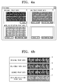
- FIGs. 4A and 4B are views showing the result of the operation in FIG. 3.
- FIG. 4A shows the result of changing the halftoned print data to an appropriate dot pattern extracted from the plurality of dot patterns through the operation of changing the halftoned print data, as illustrated in FIG. 3, and, for comparison, the halftoned print data according to the conventional method.
- Halftoned print data B is the result of halftoning the original print data A according to the conventional method.
- Modeling reflection print data C is the result of dividing the halftoned print data B into data areas in the data area dividing unit 140, extracting each dot pattern corresponding to the divided data areas, and changing each data area to the extracted dot patterns.
- the modeling technique is reflected in the dot pattern generated in the dot pattern generator 120 and, accordingly, new print data generated by the pattern converter 160 is referred to as the modeling reflection print data C.
- the modeling reflection print data C which takes into account print characteristics of the print engine, has a higher quality than the halftoned print data B obtained through the conventional method.
- FIG. 4B illustrates another example of the original print data A and the halftoned print data B in the same manner as in FIG. 4A, except that scanned print data D obtained by scanning the halftoned print data B is illustrated as well.
- scanned print data D obtained by scanning the halftoned print data B is illustrated as well.
- FIG. 5 is a flowchart explaining a halftoning correction technique of an electrophotographic image forming apparatus according to an example embodiment of the present invention.
- the description of the technique refers to particular operations being taken by particular units of an image forming apparatus, other embodiments may perform the operations using different units.
- the halftoning unit 110 halftones the original print data A, obtaining halftoned print data B, as exemplified in FIGS. 4A and 4B, at blockS200.
- the data area dividing unit 140 divides the halftoned print data B generated in the halftoning unit 110 into data areas of the same size (3 ⁇ 3) as the dot patterns stored in the storage unit 130 at block S210.
- the pattern extraction unit 150 compares the data areas divided by the data area dividing unit 140 to corresponding dot patterns stored in the storage unit 130 having the same number of dots as in the data areas at block S220. At block S230, the pattern extraction unit 150 then extracts an appropriate dot pattern, which may be matched to each data area, from dot patterns having the same number of dots as in the data areas according to the comparison result obtained in block S220.
- the pattern converter 160 changes the data areas obtained at block S210 to the corresponding dot patterns extracted at block S230. Accordingly, the pattern converter 160 converts the halftoned print data B to the modeling reflection print data C at block S240.
- the print engine 170 prints the modeling reflection print data C obtained in block S240.
- the printed output outputted by the operations described above can have a higher quality than in the situation in which only halftoning by the conventional method is performed.
- the electrophotographic image forming apparatus and the halftoning correction technique thereof compensate for the halftoned print data using a plurality of dot patterns generated taking into consideration print characteristics of the print engine. Therefore, an optimal halftoning result can be obtained, considering the characteristics of the hardware.
- the process described herein may be recorded in computer-readable media including program instructions to implement various operations.
- the media may also include, alone or in combination with the program instructions, data files, data structures, and the like.
- Examples of computer-readable media include magnetic media, such as hard disks, floppy disks, and magnetic tape; optical media such as CD ROM disks and DVD; magneto-optical media, such as optical disks; and hardware devices specially configured to store and perform program instructions, such as read-only memory (ROM), random access memory (RAM), flash memory, and the like.
- the media may also be a transmission medium such as optical or metallic lines, wave guides, and the like, including a carrier wave transmitting signals specifying the program instructions, data structures, and the like.
- Examples of program instructions include both machine code, such as produced by a compiler, and files containing higher level code that may be executed by the computer using an interpreter.
- the described hardware devices may be configured to act as one or more software modules in order to perform the operations of the above-described exemplary embodiments of the present invention.
- the image forming apparatus may be any apparatus to form images on printable media, such as a printer, a photocopier, a facsimile machine, or a multifunctional product.
- the image forming apparatus may form images on any printable media, such as paper, facsimile paper, or transparent film. Accordingly, it is intended, therefore, that the present invention not be limited to the various example embodiments disclosed, but that the present invention includes all embodiments falling within the scope of the appended claims.
Landscapes
- Engineering & Computer Science (AREA)
- Multimedia (AREA)
- Signal Processing (AREA)
- Physics & Mathematics (AREA)
- General Physics & Mathematics (AREA)
- Facsimile Image Signal Circuits (AREA)
- Control Or Security For Electrophotography (AREA)
Applications Claiming Priority (1)
| Application Number | Priority Date | Filing Date | Title |
|---|---|---|---|
| KR1020060084422A KR101287452B1 (ko) | 2006-09-01 | 2006-09-01 | 전자사진방식 화상형성장치 및 그의 하프토닝 보정 방법 |
Publications (3)
| Publication Number | Publication Date |
|---|---|
| EP1895761A2 true EP1895761A2 (fr) | 2008-03-05 |
| EP1895761A3 EP1895761A3 (fr) | 2010-05-12 |
| EP1895761B1 EP1895761B1 (fr) | 2012-08-08 |
Family
ID=38562799
Family Applications (1)
| Application Number | Title | Priority Date | Filing Date |
|---|---|---|---|
| EP07109417A Not-in-force EP1895761B1 (fr) | 2006-09-01 | 2007-06-01 | Appareil de formation d'images électrophotographique et son procédé de correction de tramage |
Country Status (4)
| Country | Link |
|---|---|
| US (1) | US8014032B2 (fr) |
| EP (1) | EP1895761B1 (fr) |
| KR (1) | KR101287452B1 (fr) |
| CN (1) | CN101136995A (fr) |
Families Citing this family (4)
| Publication number | Priority date | Publication date | Assignee | Title |
|---|---|---|---|---|
| US8134750B2 (en) * | 2009-03-13 | 2012-03-13 | Ricoh Production Print Solutions LLC | Printing with alternative halftone patterns in ink jet printing to reduce ink penetration |
| JP5590960B2 (ja) * | 2010-05-06 | 2014-09-17 | キヤノン株式会社 | 画像形成装置、画像形成方法およびプログラム |
| WO2012061974A1 (fr) * | 2010-11-09 | 2012-05-18 | 北京中科纳新印刷技术有限公司 | Procédé de clichage et dispositif de stockage et de production d'informations par matrice de points d'unité |
| US8848250B2 (en) * | 2012-10-23 | 2014-09-30 | Kyocera Document Solutions Inc. | Compression of halftoned digital images |
Family Cites Families (8)
| Publication number | Priority date | Publication date | Assignee | Title |
|---|---|---|---|---|
| US4259694A (en) * | 1979-08-24 | 1981-03-31 | Xerox Corporation | Electronic rescreen technique for halftone pictures |
| US4246614A (en) * | 1979-12-26 | 1981-01-20 | Xerox Corporation | Binary graphic printer system having an electronic screen with shift control suited for rescreening |
| US4288821A (en) * | 1980-06-02 | 1981-09-08 | Xerox Corporation | Multi-resolution image signal processing apparatus and method |
| JPH05276382A (ja) * | 1991-12-26 | 1993-10-22 | Ricoh Co Ltd | 画像処理方法及びその装置 |
| JP3241157B2 (ja) | 1993-04-19 | 2001-12-25 | 富士写真フイルム株式会社 | 網点画像データ補正方法および補正機能を有する画像処理装置 |
| JP4530438B2 (ja) | 1998-08-11 | 2010-08-25 | オリンパス株式会社 | 画像形成装置 |
| KR20050113510A (ko) * | 2004-05-29 | 2005-12-02 | 삼성전자주식회사 | 하프토닝 처리장치 및 방법 |
| US7586649B2 (en) | 2004-12-27 | 2009-09-08 | Konica Minolta Business Technologies, Inc. | Method and device for compressing image data |
-
2006
- 2006-09-01 KR KR1020060084422A patent/KR101287452B1/ko not_active Expired - Fee Related
-
2007
- 2007-03-14 US US11/685,883 patent/US8014032B2/en not_active Expired - Fee Related
- 2007-04-23 CN CNA2007101044736A patent/CN101136995A/zh active Pending
- 2007-06-01 EP EP07109417A patent/EP1895761B1/fr not_active Not-in-force
Also Published As
| Publication number | Publication date |
|---|---|
| KR20080020910A (ko) | 2008-03-06 |
| EP1895761B1 (fr) | 2012-08-08 |
| US20080055650A1 (en) | 2008-03-06 |
| EP1895761A3 (fr) | 2010-05-12 |
| KR101287452B1 (ko) | 2013-07-19 |
| US8014032B2 (en) | 2011-09-06 |
| CN101136995A (zh) | 2008-03-05 |
Similar Documents
| Publication | Publication Date | Title |
|---|---|---|
| EP1739947B1 (fr) | Procédé de détermination de densité, appareil de formation d'image, et système de traitement d'image | |
| US7982913B2 (en) | Image processing apparatus and image processing method for suppressing jaggies in the edge portions of image | |
| US8711433B2 (en) | Image forming apparatus and method for making density correction in a low resolution image based on edge determination | |
| US7701610B2 (en) | Image processing apparatus capable of printing with substitute recording agent and image processing method | |
| US8520005B2 (en) | Image processing system, image formation apparatus, computer readable medium and computer data signal | |
| JP4979357B2 (ja) | 画像形成装置及びその制御方法 | |
| US20090097063A1 (en) | Image processing system and image processing method | |
| EP1895761B1 (fr) | Appareil de formation d'images électrophotographique et son procédé de correction de tramage | |
| CN102035979B (zh) | 用于多光束打印机的在位行分割处理和方法 | |
| JPH0888756A (ja) | 画像形成装置 | |
| JP2749866B2 (ja) | 画像形成装置 | |
| US20040109176A1 (en) | Printing system and distributed image forming method | |
| JP2005111852A (ja) | 画像形成装置、印刷制御方法、及びプログラム | |
| JP4653006B2 (ja) | 潜像画像、背景画像の濃度信号値を決定する方法及び装置及びプログラム | |
| US8446653B2 (en) | Image forming apparatus and image forming method which prevent toner from peeling from a secondary color area of a multicolor image while the image is on the photosensitive member of the apparatus | |
| JPH10278347A (ja) | 画像処理装置及び方法 | |
| JP2006014191A (ja) | 画像処理装置、画像処理方法、及びプログラム | |
| JP5207990B2 (ja) | 画像形成装置、画像形成方法およびプログラム | |
| JP4200928B2 (ja) | 画像形成装置、画像形成支援装置、画像形成支援方法、及びプログラム | |
| JPH1013660A (ja) | 画像処理装置およびその方法 | |
| JP2000083168A (ja) | 画像処理装置、画像処理方法および記憶媒体 | |
| JP5004735B2 (ja) | 画像形成装置、画像形成装置の制御方法、および画像形成装置の制御プログラム | |
| JP2001103278A (ja) | 画像作成装置 | |
| JP2001103279A (ja) | 画像作成装置 | |
| JP2007124503A (ja) | 画像形成装置 |
Legal Events
| Date | Code | Title | Description |
|---|---|---|---|
| PUAI | Public reference made under article 153(3) epc to a published international application that has entered the european phase |
Free format text: ORIGINAL CODE: 0009012 |
|
| AK | Designated contracting states |
Kind code of ref document: A2 Designated state(s): AT BE BG CH CY CZ DE DK EE ES FI FR GB GR HU IE IS IT LI LT LU LV MC MT NL PL PT RO SE SI SK TR |
|
| AX | Request for extension of the european patent |
Extension state: AL BA HR MK YU |
|
| PUAL | Search report despatched |
Free format text: ORIGINAL CODE: 0009013 |
|
| AK | Designated contracting states |
Kind code of ref document: A3 Designated state(s): AT BE BG CH CY CZ DE DK EE ES FI FR GB GR HU IE IS IT LI LT LU LV MC MT NL PL PT RO SE SI SK TR |
|
| AX | Request for extension of the european patent |
Extension state: AL BA HR MK RS |
|
| 17P | Request for examination filed |
Effective date: 20101025 |
|
| AKX | Designation fees paid |
Designated state(s): DE FR GB NL |
|
| 17Q | First examination report despatched |
Effective date: 20110318 |
|
| GRAP | Despatch of communication of intention to grant a patent |
Free format text: ORIGINAL CODE: EPIDOSNIGR1 |
|
| GRAS | Grant fee paid |
Free format text: ORIGINAL CODE: EPIDOSNIGR3 |
|
| GRAA | (expected) grant |
Free format text: ORIGINAL CODE: 0009210 |
|
| AK | Designated contracting states |
Kind code of ref document: B1 Designated state(s): DE FR GB NL |
|
| REG | Reference to a national code |
Ref country code: GB Ref legal event code: FG4D |
|
| RAP2 | Party data changed (patent owner data changed or rights of a patent transferred) |
Owner name: SAMSUNG ELECTRONICS CO., LTD. |
|
| REG | Reference to a national code |
Ref country code: DE Ref legal event code: R096 Ref document number: 602007024504 Country of ref document: DE Effective date: 20120927 |
|
| REG | Reference to a national code |
Ref country code: NL Ref legal event code: T3 |
|
| PLBE | No opposition filed within time limit |
Free format text: ORIGINAL CODE: 0009261 |
|
| STAA | Information on the status of an ep patent application or granted ep patent |
Free format text: STATUS: NO OPPOSITION FILED WITHIN TIME LIMIT |
|
| 26N | No opposition filed |
Effective date: 20130510 |
|
| REG | Reference to a national code |
Ref country code: DE Ref legal event code: R097 Ref document number: 602007024504 Country of ref document: DE Effective date: 20130510 |
|
| PGFP | Annual fee paid to national office [announced via postgrant information from national office to epo] |
Ref country code: GB Payment date: 20140522 Year of fee payment: 8 |
|
| PGFP | Annual fee paid to national office [announced via postgrant information from national office to epo] |
Ref country code: DE Payment date: 20140523 Year of fee payment: 8 Ref country code: NL Payment date: 20140521 Year of fee payment: 8 |
|
| PGFP | Annual fee paid to national office [announced via postgrant information from national office to epo] |
Ref country code: FR Payment date: 20140522 Year of fee payment: 8 |
|
| REG | Reference to a national code |
Ref country code: DE Ref legal event code: R119 Ref document number: 602007024504 Country of ref document: DE |
|
| GBPC | Gb: european patent ceased through non-payment of renewal fee |
Effective date: 20150601 |
|
| REG | Reference to a national code |
Ref country code: NL Ref legal event code: MM Effective date: 20150701 |
|
| REG | Reference to a national code |
Ref country code: FR Ref legal event code: ST Effective date: 20160229 |
|
| PG25 | Lapsed in a contracting state [announced via postgrant information from national office to epo] |
Ref country code: DE Free format text: LAPSE BECAUSE OF NON-PAYMENT OF DUE FEES Effective date: 20160101 Ref country code: GB Free format text: LAPSE BECAUSE OF NON-PAYMENT OF DUE FEES Effective date: 20150601 Ref country code: NL Free format text: LAPSE BECAUSE OF NON-PAYMENT OF DUE FEES Effective date: 20150701 |
|
| PG25 | Lapsed in a contracting state [announced via postgrant information from national office to epo] |
Ref country code: FR Free format text: LAPSE BECAUSE OF NON-PAYMENT OF DUE FEES Effective date: 20150630 |
|
| REG | Reference to a national code |
Ref country code: GB Ref legal event code: 732E Free format text: REGISTERED BETWEEN 20170406 AND 20170412 |
|
| REG | Reference to a national code |
Ref country code: FR Ref legal event code: TP Owner name: S-PRINTING SOLUTION CO., LTD., KR Effective date: 20170912 |