EP1896279B1 - Suspension de roue - Google Patents
Suspension de roue Download PDFInfo
- Publication number
- EP1896279B1 EP1896279B1 EP06753834A EP06753834A EP1896279B1 EP 1896279 B1 EP1896279 B1 EP 1896279B1 EP 06753834 A EP06753834 A EP 06753834A EP 06753834 A EP06753834 A EP 06753834A EP 1896279 B1 EP1896279 B1 EP 1896279B1
- Authority
- EP
- European Patent Office
- Prior art keywords
- bearing
- fork
- strut support
- axle
- suspension
- Prior art date
- Legal status (The legal status is an assumption and is not a legal conclusion. Google has not performed a legal analysis and makes no representation as to the accuracy of the status listed.)
- Not-in-force
Links
Images


Classifications
-
- B—PERFORMING OPERATIONS; TRANSPORTING
- B60—VEHICLES IN GENERAL
- B60G—VEHICLE SUSPENSION ARRANGEMENTS
- B60G3/00—Resilient suspensions for a single wheel
- B60G3/02—Resilient suspensions for a single wheel with a single pivoted arm
- B60G3/04—Resilient suspensions for a single wheel with a single pivoted arm the arm being essentially transverse to the longitudinal axis of the vehicle
- B60G3/06—Resilient suspensions for a single wheel with a single pivoted arm the arm being essentially transverse to the longitudinal axis of the vehicle the arm being rigid
-
- B—PERFORMING OPERATIONS; TRANSPORTING
- B60—VEHICLES IN GENERAL
- B60G—VEHICLE SUSPENSION ARRANGEMENTS
- B60G15/00—Resilient suspensions characterised by arrangement, location or type of combined spring and vibration damper, e.g. telescopic type
- B60G15/02—Resilient suspensions characterised by arrangement, location or type of combined spring and vibration damper, e.g. telescopic type having mechanical spring
- B60G15/06—Resilient suspensions characterised by arrangement, location or type of combined spring and vibration damper, e.g. telescopic type having mechanical spring and fluid damper
- B60G15/07—Resilient suspensions characterised by arrangement, location or type of combined spring and vibration damper, e.g. telescopic type having mechanical spring and fluid damper the damper being connected to the stub axle and the spring being arranged around the damper
-
- B—PERFORMING OPERATIONS; TRANSPORTING
- B60—VEHICLES IN GENERAL
- B60G—VEHICLE SUSPENSION ARRANGEMENTS
- B60G7/00—Pivoted suspension arms; Accessories thereof
- B60G7/008—Attaching arms to unsprung part of vehicle
-
- B—PERFORMING OPERATIONS; TRANSPORTING
- B60—VEHICLES IN GENERAL
- B60G—VEHICLE SUSPENSION ARRANGEMENTS
- B60G2200/00—Indexing codes relating to suspension types
- B60G2200/10—Independent suspensions
- B60G2200/14—Independent suspensions with lateral arms
- B60G2200/142—Independent suspensions with lateral arms with a single lateral arm, e.g. MacPherson type
- B60G2200/1424—Independent suspensions with lateral arms with a single lateral arm, e.g. MacPherson type the lateral arm having an L-shape
-
- B—PERFORMING OPERATIONS; TRANSPORTING
- B60—VEHICLES IN GENERAL
- B60G—VEHICLE SUSPENSION ARRANGEMENTS
- B60G2200/00—Indexing codes relating to suspension types
- B60G2200/40—Indexing codes relating to the wheels in the suspensions
- B60G2200/422—Driving wheels or live axles
-
- B—PERFORMING OPERATIONS; TRANSPORTING
- B60—VEHICLES IN GENERAL
- B60G—VEHICLE SUSPENSION ARRANGEMENTS
- B60G2200/00—Indexing codes relating to suspension types
- B60G2200/40—Indexing codes relating to the wheels in the suspensions
- B60G2200/44—Indexing codes relating to the wheels in the suspensions steerable
-
- B—PERFORMING OPERATIONS; TRANSPORTING
- B60—VEHICLES IN GENERAL
- B60G—VEHICLE SUSPENSION ARRANGEMENTS
- B60G2204/00—Indexing codes related to suspensions per se or to auxiliary parts
- B60G2204/10—Mounting of suspension elements
- B60G2204/14—Mounting of suspension arms
- B60G2204/148—Mounting of suspension arms on the unsprung part of the vehicle, e.g. wheel knuckle or rigid axle
- B60G2204/1484—Mounting of suspension arms on the unsprung part of the vehicle, e.g. wheel knuckle or rigid axle on an intermediate upright strut upon which the stub axle is pivoted
-
- B—PERFORMING OPERATIONS; TRANSPORTING
- B60—VEHICLES IN GENERAL
- B60G—VEHICLE SUSPENSION ARRANGEMENTS
- B60G2204/00—Indexing codes related to suspensions per se or to auxiliary parts
- B60G2204/40—Auxiliary suspension parts; Adjustment of suspensions
- B60G2204/41—Elastic mounts, e.g. bushings
-
- B—PERFORMING OPERATIONS; TRANSPORTING
- B60—VEHICLES IN GENERAL
- B60G—VEHICLE SUSPENSION ARRANGEMENTS
- B60G2204/00—Indexing codes related to suspensions per se or to auxiliary parts
- B60G2204/40—Auxiliary suspension parts; Adjustment of suspensions
- B60G2204/416—Ball or spherical joints
Definitions
- the invention relates to a suspension, in particular front suspension for a motor vehicle with an axle, which is mounted about a vertical steering axis in an upper and a lower bearing pivotally mounted on a forked strut support, wherein the upper and the lower bearing in laterally from a base of Fork support projecting fork arms are formed with a spring and a damper consisting of a strut connecting the strut support to the body of the vehicle for receiving the vehicle load, with a wishbone, each with a substantially extending in the longitudinal direction of the vehicle horizontal axis on the one hand is connected to the body and on the other hand with the strut support, wherein the body-side axis consists of two bearings and the lower fork arm of the fork-shaped strut support has two opposing spaced apart jaws.
- connection of the wishbone with the strut support (also called just fork) is realized as follows.
- the fork has two spaced arms, between which extends a bearing axis on which a bearing eye connected to the wishbone is mounted.
- a bearing bush made of plastic, in which the side forces occurring during cornering are supported.
- the socket has a certain rigidity.
- the fork is rotated by the lateral forces acting on the wheel about a substantially vertical axis, so that the disturbing force lever arm is undesirably increased.
- the steering angle of the wheels ie their angular position to the body, not clearly defined by the steering angle, that is, by the rotation of the axle carrier with respect to the fork.
- the occurring during braking and acceleration between the fork and axle longitudinal forces are not sufficiently attenuated.
- the invention is thus based on the task of improving the steering, braking and acceleration behavior of the suspension with simple means.
- the invention provides that the suspension of the wishbone on the fork-shaped strut support consists of two spaced bearings, which lie relative to the direction of travel before and behind the steering axis and form a double bearing (19), including the outer end of the control arm (5) is located between the jaws and in the jaws in each case a bearing eye is formed, which is mounted on one of two laterally from the end of the control arm (5) projecting axle journals by means of bearing bushes (23, 24).
- the double bearing has a mobility along the bearing axis, there is, in order to avoid damage, between the opposite surfaces on the control arm and on the fork in each case radially to the bearing axis a stop disc having a suitable starting contour.
- the stop disks are formed either as individual components or as an integral part of the fork or the control arm.
- the bearing bushes additionally have protruding from the bearing eye, radially outwardly facing flanges, which are brought to bear against the stop plate and serve as a rubber buffer.
- connection of the axle carrier with the fork has an upper and a lower bearing, wherein the upper bearing consists of a bearing ball, which is located in a bearing cup on the fork and the lower bearing is designed as a pivot bearing.
- the axle can easily pivot, depending on the flexibility of the pivot bearing in all directions and thus support the steering behavior of the suspension.
- the steering axle In order to achieve a trailing axle, the steering axle is tilted backwards in the direction of travel.
- the free adjustment of the steering axle opposite the orientation of the strut and the orientation of the shock absorber to the body and the adjustability of the steering parameters are considered independent of the parameters of the rebound and rebound kinematics as an advantage of the present axis type.
- the pivot axis in which the wishbone is attached to the fork, is preferably located below the lower bearing of the axle carrier on the fork. But there are also particularly compact solutions are conceivable in which the pivot bearing between the two bearings of the axle carrier is located on the fork.
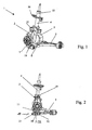
- the suspension 1 consists of an axle 2, a fork-shaped strut support 3, a strut 4 and a wishbone 5.
- the axle 2 serves to receive a wheel axle 6, which ends in a ring 7, to which the wheel rim is screwed.
- the axle carrier 2 further has a link arm 8, which is connected to the steering gear.
- the fork-shaped strut support 3 has at its upper end an upper fork arm with an upper bearing 10 for the axle 2 and at its lower end a lower fork arm with a lower bearing 11, which is shown here concealed.
- the base of the fork-shaped strut support 3 consists of two arcuate sections which leave an opening between them, through which the drive axle for the wheel bearing is passed.
- a shock absorber 4 which essentially consists of a damper 15 and a base 16 for a spring, not shown here.
- the upper end of the strut 4 is connected in a known manner to the body of the vehicle, wherein the spring is supported on the body and thus transmits the vehicle load to the suspension.
- the upper attachment of the strut 4 to the body is designed so that the strut 4 can tilt easily in all directions.
- FIG. 2 shows a side view, wherein like parts with the same reference numerals as in FIG. 1 are provided.
- the body-side end of the transverse link 5 is significantly wider and has two bearings there, with which it is fastened to the body or to a body frame in two pivot bearings whose axes extend in the vehicle longitudinal direction.
- the one bearing is viewed in the transverse direction immediately behind the axle, the other seen in the direction of travel behind the one bearing.
- FIG. 3 shows a representation of a double bearing 19, with the wishbone 5 is mounted on the fork-shaped strut support 3.
- the wishbone 5 has a solid extension 20, on which there is a respective jaw 21, 22 of the fork-shaped lower fork arm on both sides.
- the jaws 21, 22 each have a bearing eye, each with a bearing bush 23, 24 is formed.
- Through the extension 20 extends a bearing axis 25, on both sides of the extension projecting axle journal, the bearing bushes 23, 24 are located.
- FIG. 4 shows a cross section through the suspension.
- the upper bearing 10 consists of a bearing ball 30 in a bearing cup 31 in the upper fork arm of the strut support 3, while it is in the lower bearing 11 is a vertically aligned pivot bearing.
- other types of bearings can be installed: Instead of the upper ball joint z.
- B. a double-row angular contact ball bearing unit and the lower pivot bearing can be replaced by a single-row spherical roller bearings or by a simple sliding bushing.
- the defined by the two bearings 10, 11 steering axle 32 is slightly tilted inwards.
- the double bearing 19 is located slightly below, inwardly offset, from the lower bearing 11. If the position of the brake disk within the wheel rim and the approach to steering allow it, it is also possible to further divide the upper and lower bearings 10, 11 apart set and to arrange the double bearing 19 vertically between them. This solution is in the Fig. 5 shown in perspective, wherein the Fig. 6 the solution again shows schematically.
- Fig. 7 schematically shows a slightly different arrangement of the double bearing 19.
- the double bearing facing the end of the control arm 5 is forked and forms two jaws 21, 22, between which extends the lower fork arm of the strut support 3.
- the bearing eyes are formed. From the lower fork arm are laterally projecting into the bearing lugs bearing pin and thus form the bearing axis 25 of the double bearing 19th
Landscapes
- Engineering & Computer Science (AREA)
- Mechanical Engineering (AREA)
- Vehicle Body Suspensions (AREA)
- Transition And Organic Metals Composition Catalysts For Addition Polymerization (AREA)
Claims (10)
- Suspension de roue (1), en particulier suspension de roue avant, pour un véhicule à moteur avec un support d'essieu (2) pouvant pivoter autour d'un axe de guidage vertical dans un palier supérieur (10) et un palier inférieur (11) sur un appui de jambe de force à ressort (3) en forme de fourche, dans lequel le palier supérieur (10) et le palier inférieur (11) sont formés dans des bras de fourche s'écartant latéralement à partir d'une base de l'appui de jambe de force à ressort (3), avec une jambe de force à ressort (14) composée d'un ressort et d'un amortisseur (15), qui relie l'appui de jambe de force à ressort (3) à la carrosserie du véhicule pour recevoir la charge du véhicule, avec une bielle transversale (5) qui est reliée d'une part à la carrosserie avec un axe horizontal dans le sens longitudinal du véhicule et d'autre part à l'appui de jambe de force à ressort (3), l'axe du côté de la carrosserie se composant de deux paliers et le bras de fourche inférieur de l'appui de jambe de force à ressort (3) possédant deux mâchoires (21, 22) espacées se faisant face, caractérisée en ce que l'appui de la bielle transversale (5) sur l'appui de jambe de force à ressort (3) en forme de fourche se compose de deux paliers espacés qui se trouvent avant et après l'axe de guidage (32) dans le sens de la marche et forment un double palier (19), ce pour quoi l'extrémité extérieure de la bielle transversale (5) se trouve entre les mâchoires et un oeillet de support est formé dans chacune des mâchoires et supporté sur un de deux pivots d'axe dépassant latéralement de l'extrémité de la bielle transversale (5) au moyen de coussinets (23, 24).
- Suspension de roue selon la revendication 1, caractérisée en ce qu'un disque de butée (26, 27) est prévu entre chacun des deux oeillets de support et la saillie (20).
- Suspension de roue selon la revendication 2, caractérisée en ce que les coussinets (23, 24) présentent en outre des brides (28) dépassant de l'oeillet de palier et dirigées vers l'extérieur dans le sens radial, qui sont amenées à reposer sur le disque de butée (26, 27) et servent de tampons en caoutchouc.
- Suspension de roue selon la revendication 1, caractérisée en ce que les coussinets (23, 24) présentent une grande rigidité latérale et une faible rigidité perpendiculairement à celle-ci.
- Suspension de roue selon la revendication 1 ou 4, caractérisée en ce que les deux coussinets (23, 24) formant le double palier sont conçus comme des paliers de pivotement.
- Suspension de roue selon la revendication 1, caractérisée en ce que la liaison du support d'essieu (2) avec l'appui de jambe de force à ressort (3) en forme de fourche possède un palier supérieur et un palier inférieur (10, 11), le palier supérieur (10) se composant d'une rotule de palier (30) qui repose dans une cuvette de palier (31) dans le bras supérieur de l'appui de jambe de force à ressort (3) en forme de fourche et le palier inférieur (11) étant conçu comme un palier pivotant.
- Suspension de roue selon la revendication 6, caractérisée en ce que l'axe de guidage (32) est incliné vers l'arrière dans le sens de la marche.
- Suspension de roue selon la revendication 7, caractérisée en ce que l'axe de guidage (32) est incliné vers l'intérieur et orienté parallèlement à la jambe de force à ressort (4).
- Suspension de roue selon l'une des revendications 1 à 8, caractérisée en ce que le double palier (19) dans lequel la bielle transversale (5) est fixée sur l'appui de jambe de force à ressort (3) en forme de fourche se trouve de préférence sous le palier inférieur (11) du support d'essieu (2) sur l'appui de jambe de force à ressort (3) en forme de fourche.
- Suspension de roue selon l'une des revendications 1 à 8, caractérisée en ce que le double palier (19) se trouve entre les deux paliers (10, 11) du support d'essieu (2) sur l'appui de jambe de force à ressort (3) en forme de fourche.
Applications Claiming Priority (2)
| Application Number | Priority Date | Filing Date | Title |
|---|---|---|---|
| DE102005029641.6A DE102005029641B4 (de) | 2005-06-23 | 2005-06-23 | Radaufhängung |
| PCT/EP2006/004937 WO2006136259A1 (fr) | 2005-06-23 | 2006-05-24 | Suspension de roue |
Publications (2)
| Publication Number | Publication Date |
|---|---|
| EP1896279A1 EP1896279A1 (fr) | 2008-03-12 |
| EP1896279B1 true EP1896279B1 (fr) | 2010-09-01 |
Family
ID=36809247
Family Applications (1)
| Application Number | Title | Priority Date | Filing Date |
|---|---|---|---|
| EP06753834A Not-in-force EP1896279B1 (fr) | 2005-06-23 | 2006-05-24 | Suspension de roue |
Country Status (6)
| Country | Link |
|---|---|
| US (1) | US8152185B2 (fr) |
| EP (1) | EP1896279B1 (fr) |
| CN (1) | CN101203392B (fr) |
| AT (1) | ATE479562T1 (fr) |
| DE (2) | DE102005029641B4 (fr) |
| WO (1) | WO2006136259A1 (fr) |
Families Citing this family (32)
| Publication number | Priority date | Publication date | Assignee | Title |
|---|---|---|---|---|
| US8690177B2 (en) * | 2012-08-16 | 2014-04-08 | Ford Global Technologies, Llc | Front wheel suspension for a motor vehicle |
| DE102008048178A1 (de) | 2008-09-20 | 2010-04-01 | GM Global Technology Operations, Inc., Detroit | Einzelradaufhängung für Kraftfahrzeug mit Sturzeinstellung |
| MX2011003159A (es) * | 2008-09-26 | 2011-07-12 | M B Gerrard V Miles B Gerrard | Suspension para vehiculo. |
| CN101693438B (zh) * | 2009-09-28 | 2012-05-23 | 北京航天发射技术研究所 | 一种重载型油气弹簧独立悬架转向驱动桥 |
| JP5427621B2 (ja) * | 2010-01-15 | 2014-02-26 | 本田技研工業株式会社 | 車両 |
| DE102012011865A1 (de) * | 2012-06-14 | 2013-12-19 | Daimler Ag | Radaufhängung |
| DE102012011868A1 (de) * | 2012-06-14 | 2013-12-19 | Daimler Ag | Radaufhängung |
| DE102012023402A1 (de) | 2012-11-30 | 2014-06-05 | GM Global Technology Operations LLC (n. d. Ges. d. Staates Delaware) | Radaufhängung und kraftfahrzeug |
| CN103121387B (zh) * | 2013-02-07 | 2015-07-22 | 柳州孔辉汽车科技有限公司 | 麦弗逊空气悬架及其装配方法 |
| DE102013220319A1 (de) * | 2013-10-09 | 2015-04-09 | Zf Friedrichshafen Ag | Hilfsrahmen mit Achsträger und Federbeindom |
| US9186944B2 (en) | 2014-02-07 | 2015-11-17 | GM Global Technology Operations LLC | Cam adjustable shim assembly |
| DE102014109038A1 (de) * | 2014-06-27 | 2015-12-31 | Benteler Automobiltechnik Gmbh | Radaufhängung |
| JP6527350B2 (ja) * | 2015-03-04 | 2019-06-05 | 本田技研工業株式会社 | ストラット式サスペンション装置 |
| US9676240B2 (en) | 2015-04-13 | 2017-06-13 | Reyco Granning, Llc | IFS including control arm and strut supported by steering knuckle load arm |
| US9475357B1 (en) | 2015-04-13 | 2016-10-25 | Reyco Granning, Llc | Strut and air spring IFS assembly maximizing available steering knuckle wheel cut |
| US9550402B2 (en) | 2015-04-13 | 2017-01-24 | Reyco Granning, Llc | Independent front suspension module for installation into a vehicle |
| US9475354B1 (en) | 2015-04-13 | 2016-10-25 | Reyco Granning, Llc | IFS including strut pivotally secured to chassis with clevis ring |
| US9550401B2 (en) | 2015-04-13 | 2017-01-24 | Reyco Granning, Llc | IFS including strut pivotally secured to chassis through torque tube assembly |
| CN104875574B (zh) * | 2015-06-23 | 2017-06-09 | 安徽江淮汽车集团股份有限公司 | 一种麦弗逊独立悬架总成 |
| DE102016206461A1 (de) | 2016-04-18 | 2017-10-19 | Bayerische Motoren Werke Aktiengesellschaft | Radaufhängung eines Fahrzeuges mit zumindest einem Lenker |
| DE102017208554A1 (de) * | 2017-05-19 | 2018-11-22 | Bayerische Motoren Werke Aktiengesellschaft | Radaufhängung für ein zumindest geringfügig aktiv lenkbares Hinterrad eines zweispurigen Fahrzeugs, Achse mit einer Radaufhängung und Fahrzeug mit einer Radaufhängung |
| KR102138687B1 (ko) * | 2019-05-27 | 2020-07-28 | 주식회사 센트랄 | 스트러트 현가장치 |
| US11364757B2 (en) * | 2019-06-28 | 2022-06-21 | Ree Automotive Ltd | Device and method for double-arm suspension and in-wheel steering |
| KR20220128476A (ko) | 2020-01-28 | 2022-09-20 | 리 오토모티브 리미티드 | 휠 중심에서 벗어난 아암을 갖는 휠 서스펜션 시스템 |
| KR102764063B1 (ko) * | 2020-06-22 | 2025-02-05 | 현대자동차주식회사 | 서스펜션 결합 구조 |
| KR102764062B1 (ko) | 2020-06-22 | 2025-02-05 | 현대자동차주식회사 | 서스펜션 결합 구조 |
| KR102764079B1 (ko) | 2020-08-24 | 2025-02-05 | 현대자동차주식회사 | 차량용 서스펜션 시스템 |
| KR102313267B1 (ko) * | 2021-04-14 | 2021-10-14 | 서한산업(주) | 전동식 독립 조향장치 |
| US11772442B2 (en) * | 2021-07-23 | 2023-10-03 | Rivian Ip Holdings, Llc | Offset steering axis knuckle system |
| KR20240043826A (ko) * | 2022-09-27 | 2024-04-04 | 현대자동차주식회사 | 차량용 서스펜션 장치 |
| DE102024107436A1 (de) * | 2024-03-15 | 2025-09-18 | Bayerische Motoren Werke Aktiengesellschaft | Radaufhängung für eine Vorderachse eines Fahrzeugs, Verfahren zum Betreiben einer Radaufhängung und Fahrzeug |
| CN223173899U (zh) * | 2024-08-26 | 2025-08-01 | 宁德时代(上海)智能科技有限公司 | 悬架结构及车辆 |
Family Cites Families (30)
| Publication number | Priority date | Publication date | Assignee | Title |
|---|---|---|---|---|
| US234504A (en) * | 1880-11-16 | Vania | ||
| DE2249971A1 (de) * | 1972-10-12 | 1974-04-18 | Daimler Benz Ag | Aufhaengung lenkbarer fahrzeugraeder, insbesondere vorderraeder von kraftfahrzeugen |
| DE2264278C3 (de) * | 1972-12-30 | 1980-12-18 | Daimler-Benz Ag, 7000 Stuttgart | Vorderradaufhängung für Personenkraftwagen |
| DE2264300B2 (de) * | 1972-12-30 | 1975-09-18 | Daimler-Benz Ag, 7000 Stuttgart | Vorderradaufhängung für Personenkraftwagen |
| FR2441526A1 (fr) * | 1978-11-14 | 1980-06-13 | Renault | Train avant pour vehicule automobile |
| JP2635546B2 (ja) * | 1985-12-24 | 1997-07-30 | 日産自動車株式会社 | リヤサスペンション |
| JPH0625362Y2 (ja) * | 1987-10-23 | 1994-07-06 | トヨタ自動車株式会社 | 車両用サスペンシヨンのアライメント調整装置 |
| US4995633A (en) * | 1988-09-05 | 1991-02-26 | Toyota Jidosha Kabushiki Kaisha | Strut type suspension |
| FR2663266B1 (fr) * | 1990-06-15 | 1992-10-16 | Peugeot | Dispositif de liaison d'une roue directrice a la caisse d'un vehicule automobile. |
| US5192100A (en) * | 1990-12-26 | 1993-03-09 | Ford Motor Company | Independent suspension with double isolated suspension unit |
| US5180180A (en) * | 1991-04-24 | 1993-01-19 | Aisin Aw Co., Ltd. | Wheel supporting apparatus |
| US5439203A (en) * | 1991-10-24 | 1995-08-08 | Toyoda Gosei Co., Ltd. | Vibration-damping bushing with sliding surface on insert located between inner and outer cylinders |
| DE4206896C2 (de) * | 1992-03-05 | 1994-09-01 | Bayerische Motoren Werke Ag | Radaufhängung für lenkbare Räder von Kraftfahrzeugen |
| JP3464684B2 (ja) * | 1993-01-19 | 2003-11-10 | 本田技研工業株式会社 | 操舵輪懸架装置 |
| US5467971A (en) * | 1994-08-08 | 1995-11-21 | General Motors Corporation | Strut assembly with integral bearing and spring seat |
| JP3550908B2 (ja) * | 1996-10-04 | 2004-08-04 | 日産自動車株式会社 | フロントサスペンション装置 |
| GB9625863D0 (en) * | 1996-12-12 | 1997-01-29 | T & N Technology Ltd | Suspension and braking assembly |
| DE19720639A1 (de) * | 1997-05-16 | 1998-11-19 | Audi Ag | Lageranordnung für ein schwenkbares Bauteil |
| DE19949452B4 (de) * | 1999-10-14 | 2005-10-27 | Daimlerchrysler Ag | Kurbelschleifenachse mit sich windschief kreuzenden Mittellinien von Federbein und Radschwenkachse |
| US20030057622A1 (en) * | 2001-09-27 | 2003-03-27 | Bovio Vincent G. | Slipper bushing |
| EP1319533A1 (fr) * | 2001-12-14 | 2003-06-18 | Ford Global Technologies, Inc., A subsidiary of Ford Motor Company | Suspension de roue pour un véhicule |
| US6715776B2 (en) * | 2002-08-12 | 2004-04-06 | Juei-Chuan Lin | Wheel securing structure for a remote-controlled model car |
| US6783137B2 (en) * | 2002-11-14 | 2004-08-31 | Tuthill Corporation | Steering knuckle carrier-to-suspension arm pivotal connection and method of assembling and preloading the pivotal connection |
| US6880841B2 (en) * | 2003-02-10 | 2005-04-19 | Visteon Global Technologies, Inc. | Integrated wheel end for a wheel suspension of a motor vehicle |
| JP3944907B2 (ja) * | 2003-03-14 | 2007-07-18 | マツダ株式会社 | 自動車のフロントサスペンション装置 |
| DE10327554A1 (de) | 2003-06-18 | 2005-01-13 | Volkswagen Ag | Federbeinachse für ein Kraftfahrzeug |
| US7798506B2 (en) * | 2003-10-03 | 2010-09-21 | Gpv, L.L.C. | Wheel suspension system for vehicles |
| EP1582438B1 (fr) * | 2004-04-01 | 2008-06-11 | Ford Global Technologies, LLC | Dispositif de suspension dirigeable de roue de véhicule |
| US7490840B2 (en) * | 2005-06-23 | 2009-02-17 | Gm Global Technology Operations, Inc. | Steering and suspension system for a vehicle |
| DE102008048178A1 (de) | 2008-09-20 | 2010-04-01 | GM Global Technology Operations, Inc., Detroit | Einzelradaufhängung für Kraftfahrzeug mit Sturzeinstellung |
-
2005
- 2005-06-23 DE DE102005029641.6A patent/DE102005029641B4/de not_active Expired - Fee Related
-
2006
- 2006-05-24 US US11/993,246 patent/US8152185B2/en not_active Expired - Fee Related
- 2006-05-24 DE DE502006007782T patent/DE502006007782D1/de active Active
- 2006-05-24 AT AT06753834T patent/ATE479562T1/de active
- 2006-05-24 WO PCT/EP2006/004937 patent/WO2006136259A1/fr not_active Ceased
- 2006-05-24 EP EP06753834A patent/EP1896279B1/fr not_active Not-in-force
- 2006-05-24 CN CN2006800221811A patent/CN101203392B/zh not_active Expired - Fee Related
Also Published As
| Publication number | Publication date |
|---|---|
| US8152185B2 (en) | 2012-04-10 |
| DE502006007782D1 (de) | 2010-10-14 |
| DE102005029641B4 (de) | 2020-04-30 |
| ATE479562T1 (de) | 2010-09-15 |
| DE102005029641A1 (de) | 2007-01-04 |
| WO2006136259A1 (fr) | 2006-12-28 |
| CN101203392A (zh) | 2008-06-18 |
| EP1896279A1 (fr) | 2008-03-12 |
| CN101203392B (zh) | 2011-06-08 |
| US20100320711A1 (en) | 2010-12-23 |
Similar Documents
| Publication | Publication Date | Title |
|---|---|---|
| EP1896279B1 (fr) | Suspension de roue | |
| DE102010061008B4 (de) | Aktive-Geometrie-Steuerung-Aufhängungssystem und Betätigungsvorrichtung zum Antreiben derselben | |
| EP0656270B1 (fr) | Suspension de roue | |
| DE19832384C1 (de) | Einzelradaufhängung in Schräg-, Längs- oder Verbundlenkerbauweise mit einem abgekoppelten Radträger | |
| EP2512842B1 (fr) | Suspension de roue individuelle d'une roue non dirigeable d'un véhicule à deux voies | |
| EP2514616B1 (fr) | Suspension de roue pour un axe d'un véhicule automobile | |
| EP2497660B1 (fr) | Axe de véhicule automobile doté d'un axe de direction virtuel | |
| EP2033820A1 (fr) | Essieu arrière à traverse déformable en torsion pour véhicule | |
| DE102016220786B4 (de) | Hinterradaufhängung für Kraftfahrzeuge | |
| EP3074296B1 (fr) | Châssis auxiliaire à ressort à lames transversal intégré | |
| DE102006016762A1 (de) | Achsschenkel für ein Fahrzeug | |
| DE102019202910A1 (de) | Hinterradaufhängung | |
| DE102022102115A1 (de) | Radaufhängung, eine Achse sowie ein Fahrzeug | |
| DE3716706A1 (de) | Unabhaengige radaufhaengung fuer lenkbare raeder von kraftfahrzeugen | |
| DE102009035653A1 (de) | Radaufhängung an einem zweispurigen Fahrzeug | |
| DE3924717A1 (de) | Hinterradaufhaengung fuer ein kraftfahrzeug | |
| DE60306730T2 (de) | Lenkeinrichtung für die Trage-Einrichtung der Hinterradnabe in Motorfahrzeugen | |
| DE102015212580A1 (de) | Radaufhängungsanordnung | |
| DE202017100164U1 (de) | Hinterradaufhängung für Kraftfahrzeuge | |
| DE102017211277B4 (de) | Radaufhängung für ein Kraftfahrzeug | |
| DE102018220235A1 (de) | Einzelradaufhängung für ein Kraftfahrzeug | |
| DE1117403B (de) | Unabhaengige Einzelradaufhaengung fuer Kraftfahrzeuge | |
| WO2019206557A1 (fr) | Suspension de roues pour un véhicule automobile et véhicule automobile correspondant | |
| DE102019200214A1 (de) | Lenkbare Verbundlenkerachse für ein Kraftfahrzeug, Längslenker und Kraftfahrzeug | |
| DE102012221699A1 (de) | Radaufhängung für ein Fahrzeug mit aktiver Radsturzverstellung |
Legal Events
| Date | Code | Title | Description |
|---|---|---|---|
| PUAI | Public reference made under article 153(3) epc to a published international application that has entered the european phase |
Free format text: ORIGINAL CODE: 0009012 |
|
| 17P | Request for examination filed |
Effective date: 20080123 |
|
| AK | Designated contracting states |
Kind code of ref document: A1 Designated state(s): AT BE BG CH CY CZ DE DK EE ES FI FR GB GR HU IE IS IT LI LT LU LV MC NL PL PT RO SE SI SK TR |
|
| 17Q | First examination report despatched |
Effective date: 20080723 |
|
| DAX | Request for extension of the european patent (deleted) | ||
| GRAP | Despatch of communication of intention to grant a patent |
Free format text: ORIGINAL CODE: EPIDOSNIGR1 |
|
| GRAS | Grant fee paid |
Free format text: ORIGINAL CODE: EPIDOSNIGR3 |
|
| GRAA | (expected) grant |
Free format text: ORIGINAL CODE: 0009210 |
|
| AK | Designated contracting states |
Kind code of ref document: B1 Designated state(s): AT BE BG CH CY CZ DE DK EE ES FI FR GB GR HU IE IS IT LI LT LU LV MC NL PL PT RO SE SI SK TR |
|
| REG | Reference to a national code |
Ref country code: GB Ref legal event code: FG4D Free format text: NOT ENGLISH |
|
| REG | Reference to a national code |
Ref country code: CH Ref legal event code: EP |
|
| REG | Reference to a national code |
Ref country code: IE Ref legal event code: FG4D Free format text: LANGUAGE OF EP DOCUMENT: GERMAN |
|
| REF | Corresponds to: |
Ref document number: 502006007782 Country of ref document: DE Date of ref document: 20101014 Kind code of ref document: P |
|
| REG | Reference to a national code |
Ref country code: DE Ref legal event code: R096 Ref document number: 502006007782 Country of ref document: DE Effective date: 20101014 |
|
| REG | Reference to a national code |
Ref country code: NL Ref legal event code: VDEP Effective date: 20100901 |
|
| PG25 | Lapsed in a contracting state [announced via postgrant information from national office to epo] |
Ref country code: FI Free format text: LAPSE BECAUSE OF FAILURE TO SUBMIT A TRANSLATION OF THE DESCRIPTION OR TO PAY THE FEE WITHIN THE PRESCRIBED TIME-LIMIT Effective date: 20100901 Ref country code: LT Free format text: LAPSE BECAUSE OF FAILURE TO SUBMIT A TRANSLATION OF THE DESCRIPTION OR TO PAY THE FEE WITHIN THE PRESCRIBED TIME-LIMIT Effective date: 20100901 |
|
| LTIE | Lt: invalidation of european patent or patent extension |
Effective date: 20100901 |
|
| PG25 | Lapsed in a contracting state [announced via postgrant information from national office to epo] |
Ref country code: SI Free format text: LAPSE BECAUSE OF FAILURE TO SUBMIT A TRANSLATION OF THE DESCRIPTION OR TO PAY THE FEE WITHIN THE PRESCRIBED TIME-LIMIT Effective date: 20100901 Ref country code: CY Free format text: LAPSE BECAUSE OF FAILURE TO SUBMIT A TRANSLATION OF THE DESCRIPTION OR TO PAY THE FEE WITHIN THE PRESCRIBED TIME-LIMIT Effective date: 20100901 Ref country code: PL Free format text: LAPSE BECAUSE OF FAILURE TO SUBMIT A TRANSLATION OF THE DESCRIPTION OR TO PAY THE FEE WITHIN THE PRESCRIBED TIME-LIMIT Effective date: 20100901 |
|
| REG | Reference to a national code |
Ref country code: IE Ref legal event code: FD4D |
|
| PG25 | Lapsed in a contracting state [announced via postgrant information from national office to epo] |
Ref country code: SE Free format text: LAPSE BECAUSE OF FAILURE TO SUBMIT A TRANSLATION OF THE DESCRIPTION OR TO PAY THE FEE WITHIN THE PRESCRIBED TIME-LIMIT Effective date: 20100901 Ref country code: GR Free format text: LAPSE BECAUSE OF FAILURE TO SUBMIT A TRANSLATION OF THE DESCRIPTION OR TO PAY THE FEE WITHIN THE PRESCRIBED TIME-LIMIT Effective date: 20101202 Ref country code: NL Free format text: LAPSE BECAUSE OF FAILURE TO SUBMIT A TRANSLATION OF THE DESCRIPTION OR TO PAY THE FEE WITHIN THE PRESCRIBED TIME-LIMIT Effective date: 20100901 Ref country code: LV Free format text: LAPSE BECAUSE OF FAILURE TO SUBMIT A TRANSLATION OF THE DESCRIPTION OR TO PAY THE FEE WITHIN THE PRESCRIBED TIME-LIMIT Effective date: 20100901 |
|
| PG25 | Lapsed in a contracting state [announced via postgrant information from national office to epo] |
Ref country code: IE Free format text: LAPSE BECAUSE OF FAILURE TO SUBMIT A TRANSLATION OF THE DESCRIPTION OR TO PAY THE FEE WITHIN THE PRESCRIBED TIME-LIMIT Effective date: 20100901 |
|
| REG | Reference to a national code |
Ref country code: DE Ref legal event code: R081 Ref document number: 502006007782 Country of ref document: DE Owner name: GM GLOBAL TECHNOLOGY OPERATIONS LLC (N. D. GES, US Free format text: FORMER OWNER: GM GLOBAL TECHNOLOGY OPERATIONS, INC., DETROIT, US Effective date: 20110323 Ref country code: DE Ref legal event code: R081 Ref document number: 502006007782 Country of ref document: DE Owner name: GM GLOBAL TECHNOLOGY OPERATIONS LLC (N. D. GES, US Free format text: FORMER OWNER: GM GLOBAL TECHNOLOGY OPERATIONS, INC., DETROIT, MICH., US Effective date: 20110323 |
|
| PG25 | Lapsed in a contracting state [announced via postgrant information from national office to epo] |
Ref country code: CZ Free format text: LAPSE BECAUSE OF FAILURE TO SUBMIT A TRANSLATION OF THE DESCRIPTION OR TO PAY THE FEE WITHIN THE PRESCRIBED TIME-LIMIT Effective date: 20100901 Ref country code: IT Free format text: LAPSE BECAUSE OF FAILURE TO SUBMIT A TRANSLATION OF THE DESCRIPTION OR TO PAY THE FEE WITHIN THE PRESCRIBED TIME-LIMIT Effective date: 20100901 Ref country code: IS Free format text: LAPSE BECAUSE OF FAILURE TO SUBMIT A TRANSLATION OF THE DESCRIPTION OR TO PAY THE FEE WITHIN THE PRESCRIBED TIME-LIMIT Effective date: 20110101 Ref country code: EE Free format text: LAPSE BECAUSE OF FAILURE TO SUBMIT A TRANSLATION OF THE DESCRIPTION OR TO PAY THE FEE WITHIN THE PRESCRIBED TIME-LIMIT Effective date: 20100901 Ref country code: RO Free format text: LAPSE BECAUSE OF FAILURE TO SUBMIT A TRANSLATION OF THE DESCRIPTION OR TO PAY THE FEE WITHIN THE PRESCRIBED TIME-LIMIT Effective date: 20100901 Ref country code: PT Free format text: LAPSE BECAUSE OF FAILURE TO SUBMIT A TRANSLATION OF THE DESCRIPTION OR TO PAY THE FEE WITHIN THE PRESCRIBED TIME-LIMIT Effective date: 20110103 Ref country code: SK Free format text: LAPSE BECAUSE OF FAILURE TO SUBMIT A TRANSLATION OF THE DESCRIPTION OR TO PAY THE FEE WITHIN THE PRESCRIBED TIME-LIMIT Effective date: 20100901 |
|
| PG25 | Lapsed in a contracting state [announced via postgrant information from national office to epo] |
Ref country code: ES Free format text: LAPSE BECAUSE OF FAILURE TO SUBMIT A TRANSLATION OF THE DESCRIPTION OR TO PAY THE FEE WITHIN THE PRESCRIBED TIME-LIMIT Effective date: 20101212 |
|
| PLBE | No opposition filed within time limit |
Free format text: ORIGINAL CODE: 0009261 |
|
| STAA | Information on the status of an ep patent application or granted ep patent |
Free format text: STATUS: NO OPPOSITION FILED WITHIN TIME LIMIT |
|
| REG | Reference to a national code |
Ref country code: CH Ref legal event code: PFA Owner name: GM GLOBAL TECHNOLOGY OPERATIONS LLC Free format text: GM GLOBAL TECHNOLOGY OPERATIONS, INC.#300 RENAISSANCE CENTER#DETROIT, MI 48265-3000 (US) -TRANSFER TO- GM GLOBAL TECHNOLOGY OPERATIONS LLC#300 RENAISSANCE CENTER#DETROIT, MI 48265-3000 (US) |
|
| RAP2 | Party data changed (patent owner data changed or rights of a patent transferred) |
Owner name: GM GLOBAL TECHNOLOGY OPERATIONS LLC |
|
| 26N | No opposition filed |
Effective date: 20110606 |
|
| PG25 | Lapsed in a contracting state [announced via postgrant information from national office to epo] |
Ref country code: DK Free format text: LAPSE BECAUSE OF FAILURE TO SUBMIT A TRANSLATION OF THE DESCRIPTION OR TO PAY THE FEE WITHIN THE PRESCRIBED TIME-LIMIT Effective date: 20100901 |
|
| REG | Reference to a national code |
Ref country code: DE Ref legal event code: R097 Ref document number: 502006007782 Country of ref document: DE Effective date: 20110606 |
|
| BERE | Be: lapsed |
Owner name: GM GLOBAL TECHNOLOGY OPERATIONS, INC. Effective date: 20110531 |
|
| PG25 | Lapsed in a contracting state [announced via postgrant information from national office to epo] |
Ref country code: MC Free format text: LAPSE BECAUSE OF NON-PAYMENT OF DUE FEES Effective date: 20110531 |
|
| REG | Reference to a national code |
Ref country code: CH Ref legal event code: PL |
|
| PG25 | Lapsed in a contracting state [announced via postgrant information from national office to epo] |
Ref country code: LI Free format text: LAPSE BECAUSE OF NON-PAYMENT OF DUE FEES Effective date: 20110531 Ref country code: CH Free format text: LAPSE BECAUSE OF NON-PAYMENT OF DUE FEES Effective date: 20110531 |
|
| PG25 | Lapsed in a contracting state [announced via postgrant information from national office to epo] |
Ref country code: BE Free format text: LAPSE BECAUSE OF NON-PAYMENT OF DUE FEES Effective date: 20110531 |
|
| REG | Reference to a national code |
Ref country code: AT Ref legal event code: MM01 Ref document number: 479562 Country of ref document: AT Kind code of ref document: T Effective date: 20110524 |
|
| PG25 | Lapsed in a contracting state [announced via postgrant information from national office to epo] |
Ref country code: AT Free format text: LAPSE BECAUSE OF NON-PAYMENT OF DUE FEES Effective date: 20110524 |
|
| PG25 | Lapsed in a contracting state [announced via postgrant information from national office to epo] |
Ref country code: LU Free format text: LAPSE BECAUSE OF NON-PAYMENT OF DUE FEES Effective date: 20110524 |
|
| PG25 | Lapsed in a contracting state [announced via postgrant information from national office to epo] |
Ref country code: TR Free format text: LAPSE BECAUSE OF FAILURE TO SUBMIT A TRANSLATION OF THE DESCRIPTION OR TO PAY THE FEE WITHIN THE PRESCRIBED TIME-LIMIT Effective date: 20100901 Ref country code: BG Free format text: LAPSE BECAUSE OF FAILURE TO SUBMIT A TRANSLATION OF THE DESCRIPTION OR TO PAY THE FEE WITHIN THE PRESCRIBED TIME-LIMIT Effective date: 20101201 |
|
| PG25 | Lapsed in a contracting state [announced via postgrant information from national office to epo] |
Ref country code: HU Free format text: LAPSE BECAUSE OF FAILURE TO SUBMIT A TRANSLATION OF THE DESCRIPTION OR TO PAY THE FEE WITHIN THE PRESCRIBED TIME-LIMIT Effective date: 20100901 |
|
| REG | Reference to a national code |
Ref country code: FR Ref legal event code: PLFP Year of fee payment: 11 |
|
| REG | Reference to a national code |
Ref country code: FR Ref legal event code: PLFP Year of fee payment: 12 |
|
| PGFP | Annual fee paid to national office [announced via postgrant information from national office to epo] |
Ref country code: GB Payment date: 20170524 Year of fee payment: 12 Ref country code: FR Payment date: 20170413 Year of fee payment: 12 |
|
| GBPC | Gb: european patent ceased through non-payment of renewal fee |
Effective date: 20180524 |
|
| PG25 | Lapsed in a contracting state [announced via postgrant information from national office to epo] |
Ref country code: GB Free format text: LAPSE BECAUSE OF NON-PAYMENT OF DUE FEES Effective date: 20180524 Ref country code: FR Free format text: LAPSE BECAUSE OF NON-PAYMENT OF DUE FEES Effective date: 20180531 |
|
| PGFP | Annual fee paid to national office [announced via postgrant information from national office to epo] |
Ref country code: DE Payment date: 20230419 Year of fee payment: 18 |
|
| REG | Reference to a national code |
Ref country code: DE Ref legal event code: R119 Ref document number: 502006007782 Country of ref document: DE |
|
| PG25 | Lapsed in a contracting state [announced via postgrant information from national office to epo] |
Ref country code: DE Free format text: LAPSE BECAUSE OF NON-PAYMENT OF DUE FEES Effective date: 20241203 |