EP1896662B1 - Systemes et procedes de vibrations - Google Patents
Systemes et procedes de vibrations Download PDFInfo
- Publication number
- EP1896662B1 EP1896662B1 EP06750645.1A EP06750645A EP1896662B1 EP 1896662 B1 EP1896662 B1 EP 1896662B1 EP 06750645 A EP06750645 A EP 06750645A EP 1896662 B1 EP1896662 B1 EP 1896662B1
- Authority
- EP
- European Patent Office
- Prior art keywords
- vibration
- plate
- tubular member
- vibratable
- piezoelectric ring
- Prior art date
- Legal status (The legal status is an assumption and is not a legal conclusion. Google has not performed a legal analysis and makes no representation as to the accuracy of the status listed.)
- Expired - Lifetime
Links
Images





Classifications
-
- B—PERFORMING OPERATIONS; TRANSPORTING
- B05—SPRAYING OR ATOMISING IN GENERAL; APPLYING FLUENT MATERIALS TO SURFACES, IN GENERAL
- B05B—SPRAYING APPARATUS; ATOMISING APPARATUS; NOZZLES
- B05B11/00—Single-unit hand-held apparatus in which flow of contents is produced by the muscular force of the operator at the moment of use
- B05B11/01—Single-unit hand-held apparatus in which flow of contents is produced by the muscular force of the operator at the moment of use characterised by the means producing the flow
- B05B11/04—Deformable containers producing the flow, e.g. squeeze bottles
-
- B—PERFORMING OPERATIONS; TRANSPORTING
- B05—SPRAYING OR ATOMISING IN GENERAL; APPLYING FLUENT MATERIALS TO SURFACES, IN GENERAL
- B05B—SPRAYING APPARATUS; ATOMISING APPARATUS; NOZZLES
- B05B17/00—Apparatus for spraying or atomising liquids or other fluent materials, not covered by the preceding groups
- B05B17/04—Apparatus for spraying or atomising liquids or other fluent materials, not covered by the preceding groups operating with special methods
- B05B17/06—Apparatus for spraying or atomising liquids or other fluent materials, not covered by the preceding groups operating with special methods using ultrasonic or other kinds of vibrations
- B05B17/0607—Apparatus for spraying or atomising liquids or other fluent materials, not covered by the preceding groups operating with special methods using ultrasonic or other kinds of vibrations generated by electrical means, e.g. piezoelectric transducers
- B05B17/0638—Apparatus for spraying or atomising liquids or other fluent materials, not covered by the preceding groups operating with special methods using ultrasonic or other kinds of vibrations generated by electrical means, e.g. piezoelectric transducers spray being produced by discharging the liquid or other fluent material through a plate comprising a plurality of orifices
- B05B17/0646—Vibrating plates, i.e. plates being directly subjected to the vibrations, e.g. having a piezoelectric transducer attached thereto
-
- A—HUMAN NECESSITIES
- A61—MEDICAL OR VETERINARY SCIENCE; HYGIENE
- A61M—DEVICES FOR INTRODUCING MEDIA INTO, OR ONTO, THE BODY; DEVICES FOR TRANSDUCING BODY MEDIA OR FOR TAKING MEDIA FROM THE BODY; DEVICES FOR PRODUCING OR ENDING SLEEP OR STUPOR
- A61M15/00—Inhalators
- A61M15/0085—Inhalators using ultrasonics
-
- A—HUMAN NECESSITIES
- A61—MEDICAL OR VETERINARY SCIENCE; HYGIENE
- A61M—DEVICES FOR INTRODUCING MEDIA INTO, OR ONTO, THE BODY; DEVICES FOR TRANSDUCING BODY MEDIA OR FOR TAKING MEDIA FROM THE BODY; DEVICES FOR PRODUCING OR ENDING SLEEP OR STUPOR
- A61M15/00—Inhalators
-
- A—HUMAN NECESSITIES
- A61—MEDICAL OR VETERINARY SCIENCE; HYGIENE
- A61M—DEVICES FOR INTRODUCING MEDIA INTO, OR ONTO, THE BODY; DEVICES FOR TRANSDUCING BODY MEDIA OR FOR TAKING MEDIA FROM THE BODY; DEVICES FOR PRODUCING OR ENDING SLEEP OR STUPOR
- A61M15/00—Inhalators
- A61M15/009—Inhalators using medicine packages with incorporated spraying means, e.g. aerosol cans
-
- B—PERFORMING OPERATIONS; TRANSPORTING
- B05—SPRAYING OR ATOMISING IN GENERAL; APPLYING FLUENT MATERIALS TO SURFACES, IN GENERAL
- B05B—SPRAYING APPARATUS; ATOMISING APPARATUS; NOZZLES
- B05B11/00—Single-unit hand-held apparatus in which flow of contents is produced by the muscular force of the operator at the moment of use
- B05B11/01—Single-unit hand-held apparatus in which flow of contents is produced by the muscular force of the operator at the moment of use characterised by the means producing the flow
- B05B11/02—Membranes or pistons acting on the contents inside the container, e.g. follower pistons
-
- B—PERFORMING OPERATIONS; TRANSPORTING
- B05—SPRAYING OR ATOMISING IN GENERAL; APPLYING FLUENT MATERIALS TO SURFACES, IN GENERAL
- B05B—SPRAYING APPARATUS; ATOMISING APPARATUS; NOZZLES
- B05B17/00—Apparatus for spraying or atomising liquids or other fluent materials, not covered by the preceding groups
- B05B17/04—Apparatus for spraying or atomising liquids or other fluent materials, not covered by the preceding groups operating with special methods
-
- B—PERFORMING OPERATIONS; TRANSPORTING
- B05—SPRAYING OR ATOMISING IN GENERAL; APPLYING FLUENT MATERIALS TO SURFACES, IN GENERAL
- B05B—SPRAYING APPARATUS; ATOMISING APPARATUS; NOZZLES
- B05B17/00—Apparatus for spraying or atomising liquids or other fluent materials, not covered by the preceding groups
- B05B17/04—Apparatus for spraying or atomising liquids or other fluent materials, not covered by the preceding groups operating with special methods
- B05B17/06—Apparatus for spraying or atomising liquids or other fluent materials, not covered by the preceding groups operating with special methods using ultrasonic or other kinds of vibrations
- B05B17/0607—Apparatus for spraying or atomising liquids or other fluent materials, not covered by the preceding groups operating with special methods using ultrasonic or other kinds of vibrations generated by electrical means, e.g. piezoelectric transducers
- B05B17/0653—Details
- B05B17/0676—Feeding means
-
- Y—GENERAL TAGGING OF NEW TECHNOLOGICAL DEVELOPMENTS; GENERAL TAGGING OF CROSS-SECTIONAL TECHNOLOGIES SPANNING OVER SEVERAL SECTIONS OF THE IPC; TECHNICAL SUBJECTS COVERED BY FORMER USPC CROSS-REFERENCE ART COLLECTIONS [XRACs] AND DIGESTS
- Y10—TECHNICAL SUBJECTS COVERED BY FORMER USPC
- Y10T—TECHNICAL SUBJECTS COVERED BY FORMER US CLASSIFICATION
- Y10T29/00—Metal working
- Y10T29/42—Piezoelectric device making
Definitions
- This invention relates generally to a vibration system that efficiently transfers radial vibration from a vibration-inducing member to produce axial vibration in a vibratable member through a support member that filters out undesirable vibration.
- a piezoelectric transducer imparts ultrasonic oscillation to a vibratable plate, particularly a vibrating aperture (orifice) plate of an aerosol generator device, wherein the vibrating plate is perforated with holes and is operable in a fluid medium.
- the invention may also useful in the field of ultrasonic wave transmission in a fluid medium including, but not limited to, underwater sonar, depth sonar and obstacle detecting sonar.
- a circular aperture plate is vibrated using a piezoelectric transducer in the form of a ring
- a vibratable plate having at least one nozzle opening therein is secured to a rigid housing and a piezoelectric ring is secured to the vibratable plate for inducing therein a displacement to discharge a small quantity of liquid through the nozzle opening.
- a circular vibratable plate is directly bonded to the piezoelectric ring and covers the central opening in the piezoelectric ring; for example, as described in Toda U.S. Pat. No. 5,297,734 .
- Humberstone et al U.S. Pat. No. 5,518,179 Ross et al U.S. Pat. No. 5,261,601 and Davison et al U.S. Pat. No. 6,062,212 describe vibrating devices wherein a circular vibratable plate is mounted over the central opening of a thin annular member, or "washer", which is bonded to a piezoelectric ring. When actuated, the piezoelectric ring vibrates radially to cause the washer to operate in a "bending mode" that vibrates the vibratable plate in the axial direction. When these types of devices are manufactured the components must be carefully aligned concentrically with each other when the vibratable plate is attached to the washer and the washer is positioned over the opening in the piezoelectric ring.
- the above-described devices translate the radial vibration of a piezoelectric ring to axial vibration of a perforate plate to disperse a liquid as an aerosol.
- the piezoelectric transducer may be tubular and may expand and contract axially (in the direction of the central axis of the tube) to move a perforate plate.
- a piezoelectric transducer that operates in a fluid medium, such as those used in aerosolizers
- a fluid medium such as those used in aerosolizers
- insulation may be provided by encasing the piezoelectric element with elastomer material.
- Such material while providing electrical insulation, also has energy-absorbing characteristics that dampen the oscillation amplitude of the piezoelectric transducer and therefore has an adverse effect of the efficiency of the device.
- US 6,651,626 describes a method of delivering a nebulised fluid for inhalation, comprising the steps of providing a nebulising device, a reservoir and a container, the reservoir and container being adapted for holding volumes of fluids and being replaceable; delivering a volume of fluid corresponding to a selected dose size from the container to the reservoir; transferring the volume of fluid from the reservoir to the nebulizing device; using the nebulizing device to nebulize the volume of fluid; repeating the delivering and using steps a number of times with the same container; removing and replacing the container; and removing and replacing the reservoir.
- aerosolizers especially those used for medical applications using highly corrosive liquids
- contamination and corrosion of parts Certain parts of the aerosolizer that are exposed to liquids may need to be washed or disposed of in order to keep the aerosolizer in good working order. Many of these parts are difficult to clean and, since piezoelectric transducers and their associated electronics can be relatively expensive, making them disposable may not be economically feasible. Therefore, it may be desirable to make certain aerosolizer components removable or replaceable.
- a vibration system according to claim 1, and a method of making a vibration system, according to claim 26.
- One or more embodiments of the present invention are directed to a vibration system that efficiently transfers radial vibration from a vibration-inducing member to produce axial vibration in a vibratable member through a support member that filters out undesirable vibration.
- the vibration-inducing member may be an annular piezoelectric transducer having a central opening
- the vibratable member may be a thin circular plate
- the support member may have a circular cross-section for holding the circular plate; however, the components may also possibly have other shapes.
- the vibration-inducing member is separable from the other structures so that it may be reused for other applications.
- the present invention effectively isolate the vibration-inducing member from contact with liquids and is therefore particularly adapted for operation in a fluid medium, e.g. in an aerosolizer environment. Still further, the present invention provides a method for self-aligning the components of a vibration system comprising a piezoelectric ring and a circular vibratable plate so as make manufacture of the system simple and inexpensive.
- the vibration system of the present invention comprises a thin circular vibratable plate, a tubular member holding the vibratable plate and a piezoelectric ring coupled to the tubular member.
- the vibratable plate may be concentrically disposed within the lumen of a thin-walled tubular member; and a piezoelectric ring may be concentrically positioned about the outer circumference of the tubular member at the location of the vibratable plate.
- the piezoelectric ring is expandable and contractable in the radial direction, which in turn causes the walls of the tubular member to expand and contract in the radial direction. This movement of the tubular member walls expands and contracts the outer circumference of the plate causing its middle region to oscillate (i.e.
- the vibratable plate of the present invention Since the outer circumference of the vibratable plate of the present invention is positioned within the central opening of the piezoelectric ring in alignment with its central plane, in contrast to prior systems wherein a surface of the vibratable plate (or concentric washer around the plate) is secured at the surface of the piezoelectric ring across the central opening of the piezoelectric ring, the radial load produced by the piezoelectric ring is more symmetrically applied to the vibratable plate of the present invention.
- the vibratable plate may be an aperture plate that includes a plurality of tapered apertures and is preferably dome-shaped.
- the aperture plate may be coupled to a mounting structure disposed within the lumen of the tubular member that holds the aperture plate perpendicular to the central axis of the tubular member.
- the tubular member may be fabricated from a corrosive-resistant metallic material, e.g. a palladium/nickel alloy or stainless steel, and have flexible thin walls, e.g. less than 0.5 mm in thickness.
- the tubular member may comprise a plastic material, and may include at least one resilient segment, e.g. an elastomer, disposed therein that allows the tubular member to be compressed and expanded by the piezoelectric ring.
- the piezoelectric ring may be removable from the tubular member and re-used for other applications.
- the tubular member may be tapered to form a "taper lock" wherein the piezoelectric ring is press-fitted with the tubular member.
- the piezoelectric ring may be permanently bonded to the tubular member to form an integral unit.
- a tubular member containing an aperture plate may be operably coupled to a reservoir of liquid, or the reservoir may be an integral part of the tubular member, so that liquid is supplied to the aperture plate within the tubular member.
- a ring may be disposed about the outer periphery of the piezoelectric ring to assist in vibrating the aperture plate at its resonant frequency.
- tubular member and the piezoelectric ring are not integrated with the reservoir
- O-rings or other seals may be provided between the reservoir and the tubular member to serve as liquid-tight seals that prevent contamination of the piezoelectric ring, and also provide damping the piezoelectric ring and the aerosolizer housing, thereby increasing the efficiency of the system.
- the tubular member may be "press-fitted" (i.e. form an "interference fit") with a discharge opening of the reservoir.
- the reservoir and the tubular member containing the aperture plate may be integrated as a single unit, and the piezoelectric ring may be slid over the reservoir of the aerosolizer to form a press-fit with the tubular member. In this way, the piezoelectric ring may be removed without potential contamination from substances within the reservoir or tubular member, or from aerosol produced by the aperture plate. In another embodiment, the piezoelectric ring and the tubular member may be bonded together as an integral unit.
- the vibration system of the present invention may be incorporated into a variety of products and may be connected to power supplies, electronics to vibrate the vibration-inducing member, and the like.
- the vibration system of the present invention is connected to a power supply using a first wire that makes electrical contact with a first surface of the piezoelectric ring and a second wire that makes electrical contact with a second surface of the vibration-inducing member.
- These wires may be located in grooves surrounding the outer surface of the housing in which the vibration system is located so that they are isolated from liquids in the reservoir and within the tubular member of the vibration system.
- a ventilator circuit may comprise a length of tubing, and the vibration system of the present invention may be operably coupled to the tubing to introduce aerosol generated by the vibration system into the ventilator circuit.
- an aerosolizer may be constructed of a housing having a mouthpiece and the vibration system of the invention may be disposed in the housing so that liquid droplets produced by the vibrating aperture plate are ejected through the mouthpiece and into the respiratory system of the user.
- One embodiment of the invention provides an exemplary method for making a vibration system comprising the steps of inserting a vibratable plate into a support structure that surrounds the plate; surrounding the support structure including vibratable plate with a vibration-inducing member that is configured to expand and contract radially; and actuating the vibration-inducing member to produce radial expansion and contraction against the support member to cause axial vibration of the vibratable plate.
- a method of making a vibration system comprises the steps of providing a tubular member with a lengthwise lumen, securing a circular vibratable plate within the lumen so that the vibratable plate is perpendicular to the central axis of the tubular member; providing a piezoelectric ring having a center opening; positioning the tubular member within the center opening of the piezoelectric ring so that outer circumference of the tubular member is in contact with the inner circumference of the opening and the vibration-inducing member surrounds the vibratable plate within the tubular member; and securing the vibration-inducing member to the tubular member.
- a method of vibrating a plate comprises the steps of inserting a vibratable plate in a support structure that surrounds the entire periphery of the plate, inserting the support structure including vibratable plate into the central opening of a vibration-inducing member that is configured to expand and contract radially, and actuating the vibration-inducing member to produce radial expansion and contraction against the support member that causes axial vibration of the vibratable plate.
- a method of treating a patient comprises the steps of providing a vibration system comprising a circular vibratable aperture plate having an outer circumference, a tubular member concentrically disposed about the outer circumference of the vibratable plate, wherein the tubular member has an outer circumference, and an annular vibration-inducing member concentrically disposed about the outer circumference of the tubular member, wherein the vibration-inducing member is radially expandable and contractable to cause the aperture plate to vibrate in the axial direction; supplying a liquid medicament to the aperture plate via the tubular member; actuating the vibration-inducing member to vibrate the aperture plate and aerosolize the liquid medicament; and supplying the aerosol to a patient's respiratory system.
- the vibration system of the present invention comprises a vibratable plate, a support member surrounding the vibratable plate, and a vibration-inducing member surrounding the support member, wherein the vibration-inducing member is configured to radially expand and contract against the support member so as to produce axial vibration of the vibratable plate.
- the vibratable plate is circular
- the support member has a circular cross-section, e.g. a tubular member(cylindrical or tapered), into which the circular vibratable plate is disposed
- the vibration-inducing member is an annular disc having a central opening, i.e. a piezoelectric ring, into which the support member is disposed.
- the invention is not limited to this embodiment.
- the tubular member may be manufactured from a corrosion-resistant metal, for example, stainless steel (preferably grades 316, 303 or 416), titanium, or a C-276 chrome/nickel alloy (e.g. Hastelloy® C-276).
- the tubular member preferably has relatively thin walls that can be effectively deflected by the piezoelectric ring.
- the thickness of the walls of the tubular member is in the range of 0.1mm to 0.5mm, preferably about 0.25mm.
- the tubular member may have a shelf structure disposed around its inner surface to which the periphery of the vibratable plate may be bonded so that it extends across the internal lumen of the tubular member perpendicular to its central axis.
- the piezoelectric ring may comprise any material exhibiting piezoelectric properties, for example, a piezoelectric ceramic material such as lead zirconate titanate (PZT) or lead metaniobate (PN) and may take the shape of a disc of substantially constant thickness with a central hole.
- a piezoelectric ceramic material such as lead zirconate titanate (PZT) or lead metaniobate (PN)
- PZT lead zirconate titanate
- PN lead metaniobate
- Such piezoelectric rings are commercially available, e.g. from American Piezo Ceramics, Inc. (APC), Mackeyville, Pennsylvania, and from Morgan Electro Ceramics (MEC), Fairfield, New Jersey.
- the piezoelectric ring may be supplied with an alternating electric current at the selected frequency from a power source; for example, the piezoelectric ring may be electrically connected by wires to a controller that contains the electronics necessary to control the vibration of the piezoelectric ring.
- the tubular member is positioned within the center opening of the piezoelectric ring.
- the piezoelectric ring expands and contracts in the radial direction against the walls of tubular member in the vicinity of the vibratable plate.
- This movement of the tubular member walls expands and contracts the periphery of the vibratable plate, thereby forcing the center of the vibratable plate to oscillate in the axial direction, i.e. to move up and down along the central axis of the tubular member.
- the piezoelectric ring may also vibrate in the axial direction and may create a transverse surface wave, only the radial vibration can transmitted to the vibratable plate by the tubular member.
- the practice of the present invention also allows the vibration system to be installed directly to a rigid body, such as the frame or housing of an aerosolizer, nebulizer or other device, without having the vibration transfer to the entire body. This is mainly because the ends of the tubular member do not vibrate and therefore may be used to install the vibration system to the rigid body.
- the invention may be particularly useful when the tubular member is employed to hold an annular aperture plate or other structure having a plurality of apertures.
- the aperture plate oscillates in a manner that causes liquid droplets to be ejected from the apertures.
- the resultant aerosol may then be dispensed out the open end of the tubular member.
- a particularly useful type of aperture plate is one.having tapered apertures that taper from the surface contacting the liquid to the surface where the droplets are ejected.
- the aperture plate maybe domed shaped, although the invention is not limited to only such aperture plates.
- Preferred aperture plates may have a thickness in the range of 20 to 100 microns. Examples of piezoelectric materials and aperture plates that may be used with the invention are described in U.S. Patent Nos. 6,235,177 and 5,758,637 .
- the piezoelectric ring may be vibrated at a frequency in the range from about 20 Khz to about 500 Khz, for example, about 128 Khz.
- the droplets may have a size suitable for use in pharmaceutics, for example, in the range from about 3 micrometers ( ⁇ m) to about 6 ⁇ m, and the liquid may be aerosolized at a rate in the range from about 5-20 microliters/second.
- Vibration system 10 comprises vibratable plate 101, tubular member 102 and piezoelectric ring 103.
- Tubular member 102 has an outer circumference 104 and an inner circumference 105, which together define a relatively thin cylindrical wall, preferably having a thickness in the range from about 0.1mm to 0.5mm.
- the hollow center (lumen) of tubular member 102 terminates in openings 106 and 107 at opposing ends thereof.
- Mounting structure 111 comprises a circular ridge that projects perpendicularly from inner circumference 105 into the lumen of tubular member 102 at a location, preferably a central location, between openings 106 and 107.
- Piezoelectric ring 103 comprises an annular disc of piezoelectric material having a center hole 108 with a circumference 112 approximately equal to the outer circumference 104 of tubular member 102.
- Vibratable plate 101 comprises circular outer flange 109 surrounding a thin circular vibratable center portion 110.
- metallic tubular member 102 may first be provided with mounting structure 111 by bonding a ridge of metal around inner circumference 105 at a location equidistant from ends 106 and 107.
- Vibratable plate 101 may then be concentrically disposed within the lumen of tubular member 102 with the lower surface of circular flange 109 positioned over the upper surface of mounting structure 111 and with the outer periphery of vibratable plate 101 abutting inner circumference 105.
- Outer flange 109 of vibratable plate 101 may be secured onto mounting structure 111 using a suitable joining procedure, e.g. a metallurgical process such as brazing, welding, soldering or the like, or a chemical bonding process such as adhesive bonding.
- a brazing ring of a suitable corrosion-resistant brazing filler material e.g. a mixture of 70% gold and 30% copper, may be placed between the upper surface of mounting structure 111 and outer flange 109 of vibratable plate 101.
- the entire assembly of tubular member 102, vibratable plate 101 and brazing ring may be held in place by a weight placed on top of vibratable plate 101.
- the assembly may be placed in an oven and heated to a temperature sufficient to melt the brazing 1 and permanently join the surfaces together in a conventional brazing procedure.
- vibratable plate 101 may be soldered onto mounting structure 111 using soldering materials, such as a tin/lead soldering material; however, this method may not be suitable if the assembly is to be exposed to acidic pharmaceutical preparations.
- vibratable plate 101 may be secured onto mounting structure 111 by ultrasonic or laser welding.
- tubular member 102 may be positioned within center hole 108 of piezoelectric ring 103.
- tubular member 102 may be placed in a fixture that holds tubular member 102 upright, and piezoelectric ring 103 may be slid lengthwise down tubular member 102 until piezoelectric ring 103 surrounds the outer circumference 104 at a location directly corresponding to the location of mounting structure 111 and vibratable plate 101 on inner circumference 105 of tubular member 102.
- Outer circumference 104 of tubular member 102 and circumference 112 of center hole 108 in piezoelectric ring 103 may then be bonded together, e.g.
- a suitable liquid adhesive around the juncture of circumference 104 and circumference 112 and curing the adhesive, e.g. with UV light.
- the adhesive used should be capable of efficiently transferring vibration from the piezoelectric ring 103 to tubular member 102. Although ideally the adhesive would have the modulus of elasticity ("Young's Modulus") of the piezoelectric ring, i.e. about 60 GPa (Giga Pascal), to achieve the ultimate transfer of vibration, this is not possible for any adhesive. Most structural adhesives (such as epoxy) have a modulus of elasticity of plastic material, which may be about 2 GPa, and should be suitable for the present invention if cured to approximately that stiffness.
- suitable adhesives mention may be made of various epoxy and anaerobic adhesives, such as commercially available UV-cured epoxy adhesives sold under the trademark Loctite.
- piezoelectric ring 103 is configured to radially expand and contract when alternating electric fields are communicated to it via electric lines. For example, as illustrated in Fig. 3a , piezoelectric ring 103 contracts radially towards its center opening (direction D) when actuated by a first electric field. This radial contraction causes piezoelectric ring 103 to push inward along outer circumference 104 of tubular member 102 in the vicinity of mounting structure 111 and thereby pinch the wall of tubular member 102. The constriction of tubular member 102 causes flange 109 to also constrict radially and, as a result, the center portion 110 of vibratable plate 101 moves axially in direction A.
- piezoelectric ring 103 When actuated by a second electric field, as shown in Fig. 3b , piezoelectric ring 103 expands radially away from its center opening (direction D'), thereby releasing the inward pressure along circumference 104 of tubular member 102. This release of pressure allows flange 109 to expand radially, which causes center portion 110 of aperture plate 101 to move axially in direction A' to its original position. Continually alternating the electric fields produces an oscillation (vibration) of center portion 110 between the positions shown in Figs. 3a and 3b .
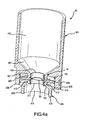
- aerosolizer 40 comprises upper housing 401, detachable lower housing 405 and vibration system 10 (e.g., see Fig. 2 ).
- Vibration system 10 comprises tubular member 102, piezoelectric ring 103 and aperture plate 101.
- Upper housing 401 comprises reservoir 402 configured to hold a volume of liquid, e.g.
- Vibration system 10 is adapted to be detachably engaged with upper housing 401, with the upper section of tubular member 102 of vibration system 10 (i.e., that section of tubular member 102 above piezoelectric ring 103) being configured to be press fit within discharge tube 404 and with piezoelectric ring 103 of vibration system 10 being configured to be press fit with engagement tube 407.
- the upper section of tubular member 102 of piezoelectric ring 103 is fully encompassed by discharge tube 404 and the top surface of piezoelectric ring 103 abuts the lower end of discharge tube 404.
- This press fit mating of tubular member 102 and discharge tube 404 forms a liquid-tight seal that prevents liquid discharged from reservoir 402 into discharge tube 404 from coming in contact with piezoelectric ring 103.
- Lower housing 405 comprises receiving tube 411 defined by cylindrical walls 412, annular flange 413 concentrically disposed around the base of receiving tube 411 and aerosol chamber 414 defined by cylindrical walls 415.
- Lower housing 405 may be adapted to be detachably engaged with vibration system 10 and upper housing 401, with the lower section of tubular member 102 of vibration system 10 (i.e., that section of tubular member 102 below piezoelectric ring 103) being configured to be press fit within receiving tube 411 and with annular flange 413 being configured to be press fit within engagement tube 407.
- the lower section of tubular member 102 is fully encompassed by receiving tube 411 and forms a passageway directly into aerosol chamber 414.
- the bottom surface of piezoelectric ring 103 abuts the upper end of receiving tube 411 to securely hold vibration system 10 within engagement tube 407.
- piezoelectric ring 103 may be supplied with an electric current by wires 416 and 417 from batteries or another power source (not shown).
- wires 416 and 417 maybe shaped in a "c-clip" arrangement and respectively nestled into grooves 418 and 419 cut around the periphery of walls 415 of upper housing 401.
- Terminal end 420 of wire 416 may enter engagement tube 407 through opening 422 in wall 415 and make electrical contact with the upper surface of piezoelectric ring 103.
- Terminal end 421 of wire 417 may enter engagement tube 407 through hole 423 in wall 415 of upper housing 401 and make electrical contact with the lower surface of piezoelectric ring 103.
- Center portion 110 of aperture plate 101 may be dome-shaped in geometry, although other shapes may be used. Also, center portion 110 may include apertures that taper from the rear side (facing reservoir 402) to the front side. When aerosolizer 40 is placed in a generally vertical orientation, the liquid from reservoir 402 may be delivered to and rest on the rear side of center portion 110 by force of gravity. Piezoelectric ring 103 is configured to radially expand and contract when actuated by alternating electric fields supplied by wires 416 and 417. In so doing, the wall of tubular member 102 also constricts and expands. In this way, center portion 110 vibrates axially so as to eject liquid droplets from its front side and out the opening in aerosol chamber 414.
- vibration system 10 may be constructed so that vibration system 10 is removable from upper housing 401 and lower housing 405. In this way, vibration system 10 (which contains relatively expensive piezoelectric ring 103) may be reused in other applications. Upper housing 401 and lower housing 405, which may be able to be produced relatively inexpensively, may be discarded after use.
- Another advantage of using vibration system 10 is that the ends of tubular member 102 may be connected directly to rigid bodies, such as wall 406 of upper housing 401 and wall 412 of lower housing 405, without affecting the oscillating amplitude of aperture plate 110. This enables aerosolizer 40 to more efficiently produce liquid droplets.
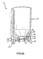
- aerosolizer 40' is similar to aerosolizer 40 and comprises upper housing 401' containing reservoir 402', detachable lower housing 405' containing aerosol chamber 414', and vibration system 10', which comprises tubular member 102', piezoelectric ring 103' and aperture plate center portion 110'.
- the upper section of tubular member 102' is not press fit into discharge tube 404' (as shown in Fig. 4a ), but rather O-rings 420 may be positioned to fill a gap between the upper section of tubular member 102' and discharge tube 404' of housing 401'.
- a liquid-tight seal is formed that prevents liquid from reservoir 402' from contacting piezoelectric ring 103'.
- O-rings 421 may be positioned to fill a gap between the lower section of tubular member 102' and receiving tube 411' of lower housing 405' to form a liquid-tight seal that prevents aerosol produced from aperture plate center portion 110' from contacting piezoelectric ring 103'.
- piezoelectric ring 103' may be protected from contamination that may prevent it from being re-usable after removal from aerosolizer 40', without the tight dimensions required for a press fit, as described in connection with aerosolizer 40.
- O-rings 420 and 421 are positioned on both top and bottom surfaces of piezoelectric ring 103' and serve to suspend piezoelectric ring 103' from direct contact with upper housing 401' and lower housing 405', O-rings 420 and 421 may also have a dampening effect that reduces the undesirable transfer of vibration from piezoelectric ring 103' to upper housing 401' and lower housing 405'.
- Vibration system 50 comprises a piezoelectric ring 502 having a central opening 504.
- Piezoelectric ring 502 may be constructed of a piezoelectric material that radially expands and contracts when actuated, as previously discussed.
- Tubular member 506 is disposed within opening 504 and is adapted to hold aperture plate 508 within its internal lumen 509 using any of the techniques described herein.
- Tubular member 506 may be constructed of a rigid material, such as a hard plastic, metal, ceramic or the like.
- Tubular member 506 may optionally include projections 510 to provide a good mechanical contact with piezoelectric ring 502. As an alternative, tubular member 506 maybe tapered to assure a good mechanical contact.
- Tubular member 506 may include one or more resilient segments 511 radially extending from locations on its inner circumference to corresponding locations on its outer circumference. These segments may be constructed from an elastomeric material and positioned in various locations. Resilient segments 511 permit tubular member 506 to be constructed of a rigid material (for securely holding aperture plate 508) while also permitting tubular member 506 to radially expand and contract with piezoelectric ring 502. More specifically, as tubular member 506 is constricted by piezoelectric ring 502, resilient segments 511 compress to reduce the diameter of lumen 509. When piezoelectric ring 502 radially expands, resilient segments 511 expand to increase the diameter of lumen 509. Hence, the amount of expansion and contraction may be varied based in part on the size, number and types of resilient materials used.
- vibration system 50 may be coupled to a reservoir of an aerosolizer (not shown) to permit a liquid to be supplied to aperture plate 508.
- aerosolizer not shown
- other liquid delivery systems could be used as well, such as wicking systems, and the like.
- vibration system 50 may be incorporated into other systems, such as nebulizers, ventilators and the like.
- Fig. 6 illustrates vibration system 50, as shown in Figs. 5a and 5b , with an outer ring 512 disposed about the outer circumference of piezoelectric ring 502, which in turn in disposed around tubular member 506.
- Ring 512 may be employed to adjust the operating frequency of piezoelectric ring 502.
- the piezoelectric ring 502 may be too large for certain applications.
- a low operating frequency of piezoelectric ring 502 may result because the piezoelectric material is "soft" and heavy.
- outer ring 512 (which may be constructed of a stiff and lightweight material, such as silicon nitride) may be added. The combination of ring 512 and piezoelectric ring 502 serves to increase the frequency to the desired range.
- System 80 includes an aerosolizer that, for convenience of discussion, includes vibration system 50 having ring 512, as shown in Fig. 6 , although it will be appreciated that other vibration systems of the invention could be used as well.
- a container 802 for holding a liquid.
- a lid 804 may be provided to close container 802 after filling it with a liquid.
- an outlet 806 is also coupled to tubular member 506 through which an aerosol produced by aperture plate 508 may be dispensed.
- O-rings or gasket seals 805 may be disposed between container 802 and vibration system 50, and between vibration system 50 and outlet 806 to provide adequate sealing and cushioning between the components.
- piezoelectric ring 502 has a large enough inner diameter that it may be slid over outlet 806 and container 802. In this way, system 80 may be easily assembled and disassembled to remove piezoelectric ring 502. Further, piezoelectric ring 502 does not come into contact with any liquids and therefore may be reused with another aerosolization system. Further, container 802, tubular member 506 and aperture plate 508 may be constructed to be relatively inexpensive so that they may be disposed of following use. Also, system 80 may easily be incorporated into other systems, such as hand-held nebulizers, ventilators and the like.
- container 802 is filled with a liquid and lid 804 is put in place.
- Piezoelectric ring 502 is slid over container 802 and placed over tubular member 506.
- An electric current is supplied to piezoelectric ring 502 to cause it to expand and contract.
- liquid that is in contact with aperture plate 508 is ejected as liquid droplets into outlet 806.
- container 802 may be refilled, or may be discarded while saving piezoelectric ring 502.
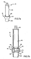
- Fig. 8 illustrates another embodiment of the invention wherein aerosolization system 90 includes tubular member 906 comprising a sharpened end 901 and a discharge end 903.
- tubular member 906 also contains an aperture plate (not shown) across its internal lumen.
- Piezoelectric ring 904 is disposed around tubular member 906.
- sharpened end 901 may have a cover (not shown) that protects it from damage and contamination.
- the cover may be removed and sharpened end 901 may be inserted through the membrane top of a vial 902, which contains liquid 905 to be aerosolized. Liquid 905 is then delivered through sharpened end 901 and the lumen of tubular member 906 to the aperture plate contained therein.
- Piezoelectric ring 904 may be actuated to vibrate the aperture plate and thereby aerosolize liquid 905 in the manner previously described. The resultant aerosol is then dispensed through discharge end 903. After use, vial 902 may be removed from sharpened end 901 and discarded, piezoelectric ring 904 may be removed from the assembly for re-use, and the remaining assembly maybe discarded.
- an aerosolizer of the present invention may be coupled to such a ventilator or CPAP circuit to supply aerosolized medicament to a patient's respiratory system, e.g. through a patient interface device.
- CPAP continuous positive pressure airway pressure
- the aerosolizer of the present invention may be incorporated in a nebulizer such as described in co-pending U.S. Patent Application No. 10/833,932, filed April 27,2004 .
- the nebulizer comprises a main housing coupled to an aerosolizer housing, which may comprise an aerosolization system such as previously described in connection with aerosolizer 40 shown in Figs. 4a , 4b and 4c , including a reservoir for holding a liquid medicament that is to be aerosolized and a vibration system according to the present invention having an aperture plate with a plurality of tapered apertures extending between a first surface and a second surface, as described in U.S. Patent Nos.
- the nebulizer may also have a mouthpiece coupled to the main housing. At least a portion of the tubular member of the vibration system of the present invention may be disposed in the housing so that liquid droplets are ejected through the mouthpiece to permit a patient to inhale the aerosolized medicament.
- the apertures in the aperture plate maybe sized to produce an aerosol in which about 70% or more of the droplets by weight have a size in the range from about 1 to about 5 micrometers.
- the aerosol housing may be removed from the main housing. The liquid may be refilled, or one or more components may be replaced. For example, the vibration system may be removed and reused with another nebulizer.
- One embodiment of the present invention provides a method of treating a patient that exhibits one or more symptoms of infection or other respiratory disease or disorder.
- the method generally comprises the steps of: providing a vibration system comprising a circular vibratable aperture plate having an outer circumference, a tubular member concentrically disposed about the outer circumference of the vibratable plate, wherein the tubular member has an outer circumference, and an annular vibration-inducing member concentrically disposed about the outer circumference of the tubular member, wherein the vibration-inducing member is radially expandable and contractable to cause the aperture plate to vibrate in the axial direction; supplying a liquid medicament to the vibration system; actuating the vibration-inducing member to vibrate the aperture plate and aerosolize the medicament; and supplying the aerosol to the patient's respiratory system.
- An aerosol generator in accordance with the present invention has the ability to produce a high flow of aerosol relative to the power input.
- the flow rate of aerosol having a volumetric median diameter (VMD) of 4 microns maybe 15 microliters/sec and the power consumption of the generator may be 3 watts.
Landscapes
- Health & Medical Sciences (AREA)
- Engineering & Computer Science (AREA)
- Bioinformatics & Cheminformatics (AREA)
- Pulmonology (AREA)
- Anesthesiology (AREA)
- Biomedical Technology (AREA)
- Heart & Thoracic Surgery (AREA)
- Hematology (AREA)
- Life Sciences & Earth Sciences (AREA)
- Animal Behavior & Ethology (AREA)
- General Health & Medical Sciences (AREA)
- Public Health (AREA)
- Veterinary Medicine (AREA)
- Special Spraying Apparatus (AREA)
- Apparatuses For Generation Of Mechanical Vibrations (AREA)
- Supports For Pipes And Cables (AREA)
- Combined Devices Of Dampers And Springs (AREA)
- Percussion Or Vibration Massage (AREA)
- Springs (AREA)
- Vibration Prevention Devices (AREA)
- Reciprocating, Oscillating Or Vibrating Motors (AREA)
- Making Paper Articles (AREA)
Claims (34)
- Système de vibration (10) qui comprend :une plaque vibrante circulaire (101) qui possède une circonférence extérieure ;un élément de support tubulaire (102) destiné à recevoir et à maintenir la plaque vibrante (101) de manière concentrique dans l'élément de support tubulaire de sorte que la plaque vibrante soit perpendiculaire à l'axe central de l'élément de support tubulaire, l'élément de support (102) entourant la circonférence extérieure de la plaque vibrante (101) et alignant la plaque vibrante (101), l'élément des support tubulaire (102) ayant une circonférence intérieure (105) et une circonférence extérieure (104) ; et dans lequel la circonférence extérieure de la plaque vibrante (101) est positionnée dans et touche la circonférence intérieure (105) de l'élément de support (102) ;un élément vibratoire annulaire (103) disposé de manière concentrique autour de la circonférence extérieure (104) de l'élément de support et entourant l'élément de support (102), l'élément vibratoire (103) étant configuré pour s'étendre et se contracter radialement contre l'élément de support (102) de façon à produire une vibration axiale de la plaque vibrante (101), etune structure de montage (111) disposée à l'intérieur de l'élément de support tubulaire (102), la structure de montage (111) supportant la plaque vibrante (101).
- Système de vibration (10) selon la revendication 1, dans lequel l'élément vibratoire (103) possède une ouverture centrale (108) dans laquelle l'élément de support (102) est disposé.
- Système de vibration (10) selon la revendication 2, dans lequel l'élément de support (102) comprend un élément tubulaire à parois minces, et l'élément vibratoire (103) est une bague piézoélectrique.
- Système de vibration (10) selon la revendication 1, dans lequel la plaque (101) comprend une pluralité d'ouvertures effilées.
- Système de vibration (10) selon la revendication 4, dans lequel la plaque (101) possède une épaisseur de l'ordre d'environ 20 microns à environ 100 microns.
- Système de vibration (10) selon la revendication 4, dans lequel la plaque (101) est en forme de dôme.
- Système de vibration (10) selon la revendication 4, qui comprend en outre un réservoir (402) de liquide qui est adapté pour fournir le liquide à la plaque (101).
- Système de vibration (10) selon la revendication 4, dans lequel l'élément tubulaire (102) comprend une extrémité pointue (901) adaptée pour extraire le liquide d'un flacon (902) de liquide en perçant une membrane qui recouvre une ouverture dans ledit flacon (902).
- Système de vibration (10) selon la revendication 1, dans lequel l'élément tubulaire (102) possède une épaisseur de parois de l'ordre d'environ 0,1 mm à environ 0,5 mm.
- Système de vibration (10) selon la revendication 1, dans lequel l'élément vibratoire (103) comprend une bague piézoélectrique.
- Système de vibration (50) selon la revendication 10, dans lequel l'élément tubulaire (506) comprend au moins un segment élastique (511) disposé à l'intérieur.
- Système de vibration (50) selon la revendication 11, dans lequel une bague est disposée autour de la circonférence extérieure de la bague piézoélectrique (502) afin d'ajuster la fréquence de fonctionnement de la bague piézoélectrique (502).
- Système de vibration (10) selon la revendication 1, qui comprend en outre un contrôleur destiné à contrôler la dilatation et la contraction radiales de l'élément vibratoire (103), et des fils (416, 417) qui relient le contrôleur à l'élément vibratoire (103).
- Système de vibration (10) selon la revendication 1, dans lequel l'élément vibratoire (103) est amovible de l'élément tubulaire (102).
- Système de vibration (10) selon la revendication 1, dans lequel l'élément vibratoire (103) est
une bague piézoélectrique qui possède un orifice central (108) avec une circonférence intérieure adaptée pour se dilater et se contracter radialement lorsqu'elle est électriquement activée, et l'élément de support (102) est un élément tubulaire disposé dans l'orifice central (108) de la bague piézoélectrique (103), ledit élément tubulaire (102) ayant une circonférence extérieure (104) en contact avec la circonférence intérieure dudit orifice central (108) et une paroi cylindrique qui définit une lumière interne qui s'étend sur la longueur de l'élément tubulaire (102) ;
au moins une connexion électrique avec ladite bague piézoélectrique (103) afin de l'actionner électriquement ;
une plaque d'ouverture vibrante circulaire (101) adaptée pour pulvériser un liquide lors d'une vibration axiale de celle-ci ;
dans lequel la plaque vibrante (101) est disposée dans la lumière interne de l'élément tubulaire (102) et en contact avec la circonférence intérieure de la lumière à un emplacement qui coïncide avec la circonférence intérieure de l'orifice central (108) de la bague piézoélectrique (103) ; et
un réservoir (402) de liquide relié à l'élément tubulaire (102) de façon à fournir le liquide à la plaque d'ouverture vibrante (101), moyennant quoi une dilatation et une contraction radiales de la bague piézoélectrique (103) contre la paroi de l'élément tubulaire (102) provoquent une vibration de la plaque vibrante (101) dans la direction axiale, et une pulvérisation du liquide. - Système de vibration (10) selon la revendication 15, dans lequel la plaque vibrante (101) est en forme de dôme et possède une pluralité d'ouvertures effilées.
- Système de vibration (10) selon la revendication 15, dans lequel la bague piézoélectrique (103) comprend un matériau céramique piézoélectrique.
- Système de vibration (10) selon la revendication 15, qui comprend en outre un circuit d'un système de ventilation relié à l'élément tubulaire (102) de façon à distribuer l'aérosol généré par ladite plaque d'ouverture vibrante (101) dans ledit circuit.
- Système de vibration (10) selon la revendication 15, dans lequel ladite bague piézoélectrique (103), ledit élément tubulaire (102), ladite plaque d'ouverture vibrante (101) et ledit réservoir (402) sont disposés dans le logement d'un nébuliseur muni d'un embout.
- Système de vibration (10) selon la revendication 1, dans lequel :l'élément de support (102) comprend une paroi cylindrique qui définit une lumière longitudinale ;la structure de montage (111) s'étend depuis la paroi cylindrique et la plaque vibrante (101) est disposée dans la lumière ; etl'élément vibratoire (103) transmet une vibration radiale à la paroi cylindrique de l'élément de support tubulaire (102) de façon à produire une vibration axiale dans la plaque vibrante (101).
- Système de vibration (10) selon la revendication 20, dans lequel la plaque vibrante (103) est une plaque d'ouverture qui possède une surface arrière en contact avec un liquide et une surface avant opposée à celui-ci, dans lequel des gouttelettes de liquide sont éjectées de la surface avant afin de former un aérosol lors de ladite vibration axiale de la plaque d'ouverture (101).
- Système de vibration (10) selon la revendication 1, dans lequel une partie du système de vibration (10) est jetable.
- Système de vibration (10) selon la revendication 1, dans lequel l'élément vibratoire (103) est en alignement coplanaire avec une périphérie de la plaque vibrante (101).
- Procédé de fabrication d'un système de vibration (10) qui comprend :l'alignement d'une plaque vibrante (101) dans un élément de support tubulaire (102) qui entoure la plaque vibrante (101), l'élément de support (102) ayant une circonférence intérieure (105), et la circonférence intérieure (105) de l'élément de support (102) étant en contact avec une circonférence extérieure de la plaque vibrante (101), et dans lequel l'alignement comprend le placement de la plaque vibrante (101) en contact avec une structure de montage (111) de l'élément de support tubulaire (102) ; etle placement, autour de l'élément de support (102), d'un élément vibratoire (103) configuré pour se dilater et se contracter radialement contre l'élément de support (102) afin de produire une vibration axiale de la plaque vibrante (101).
- Procédé selon la revendication 24, dans lequel l'élément de support (102) est un élément tubulaire qui possède une lumière dans le sens de la longueur, la plaque vibrante (101) est circulaire, et l'élément vibratoire (103) est une bague piézoélectrique, et qui comprend en outre :l'alignement et la fixation de la plaque vibrante circulaire (101) dans la lumière de sorte que la plaque (101) soit perpendiculaire à et recouvre la lumière de l'élément tubulaire (102) ;le positionnement de l'élément tubulaire (102) dans l'orifice central (108) de la bague piézoélectrique (103) de sorte que la plaque vibrante (101) dans la lumière de l'élément tubulaire (102) soit entourée par la bague piézoélectrique (103) en contact avec la circonférence extérieure (104) de l'élément tubulaire (102) ; etla fixation de la bague piézoélectrique (103) sur l'élément tubulaire (102).
- Procédé de fabrication d'un système de vibration (10) selon la revendication 25, qui comprend en outre les étapes qui consistent à :creuser une arête (111) autour de la circonférence intérieure (105) de l'élément tubulaire (102) ;positionner la plaque vibrante (101) sur l'arête (111) ; etbraser ou souder la plaque vibrante (101) sur l'arête (111).
- Procédé de fabrication d'un système de vibration (10) selon la revendication 25, dans lequel la bague piézoélectrique (103) est fixée sur l'élément tubulaire (102) avec un adhésif capable de transférer efficacement la vibration de la bague piézoélectrique (103) à l'élément tubulaire (102).
- Procédé selon la revendication 24, qui comprend en outre les étapes qui consistent à :actionner l'élément vibratoire (103) afin de produire une dilatation et une contraction radiales contre l'élément de support (102) afin de provoquer une vibration axiale de la plaque vibrante (101).
- Procédé selon la revendication 28, dans lequel l'élément de support (102) filtre les vibrations autres que les vibrations axiales.
- Procédé selon la revendication 24, dans lequel :l'élément de support (102) est un élément tubulaire qui possède une circonférence extérieure (104) ;l'élément vibratoire (103) est une bague piézoélectrique positionnée de manière concentrique autour de la circonférence extérieure (104) de l'élément tubulaire (102) à un emplacement qui coïncide avec la circonférence extérieure de la plaque (101) ; le procédé comprenant en outre :la dilatation et la contraction radiales de la bague piézoélectrique (103) contre l'élément tubulaire (102) de façon à ce que la plaque (101) vibre dans la direction axiale.
- Procédé selon la revendication 30, dans lequel la bague piézoélectrique (103) vibre à une fréquence de l'ordre d'environ 20 KHz à environ 500 KHz.
- Procédé selon la revendication 30, dans lequel la plaque (101) comprend une pluralité d'ouvertures, et comprend en outre la fourniture d'un liquide à la plaque (101) afin de pulvériser le liquide sous forme de gouttelettes.
- Procédé selon la revendication 32, dans lequel les gouttelettes possèdent une taille de l'ordre d'environ 3 micromètres à 6 micromètres, et dans lequel le liquide est pulvérisé à une vitesse d'environ 5 microlitres/seconde à environ 20 microlitres/seconde.
- Procédé selon la revendication 32, qui comprend en outre le raccordement d'un réservoir (402) à l'élément tubulaire (102) afin de fournir le liquide à la plaque (101).
Applications Claiming Priority (2)
| Application Number | Priority Date | Filing Date | Title |
|---|---|---|---|
| US68472005P | 2005-05-25 | 2005-05-25 | |
| PCT/US2006/014654 WO2006127181A2 (fr) | 2005-05-25 | 2006-04-17 | Systemes et procedes de vibrations |
Publications (3)
| Publication Number | Publication Date |
|---|---|
| EP1896662A2 EP1896662A2 (fr) | 2008-03-12 |
| EP1896662A4 EP1896662A4 (fr) | 2011-02-23 |
| EP1896662B1 true EP1896662B1 (fr) | 2014-07-23 |
Family
ID=37452540
Family Applications (1)
| Application Number | Title | Priority Date | Filing Date |
|---|---|---|---|
| EP06750645.1A Expired - Lifetime EP1896662B1 (fr) | 2005-05-25 | 2006-04-17 | Systemes et procedes de vibrations |
Country Status (23)
| Country | Link |
|---|---|
| US (4) | US9108211B2 (fr) |
| EP (1) | EP1896662B1 (fr) |
| JP (1) | JP5064383B2 (fr) |
| KR (1) | KR101314052B1 (fr) |
| CN (1) | CN101208123B (fr) |
| AU (1) | AU2006249574B2 (fr) |
| BR (1) | BRPI0611198B1 (fr) |
| CA (1) | CA2607747C (fr) |
| CR (1) | CR9631A (fr) |
| CU (1) | CU23753A3 (fr) |
| EA (1) | EA012656B1 (fr) |
| EG (1) | EG25536A (fr) |
| ES (1) | ES2514470T3 (fr) |
| IL (1) | IL187549A (fr) |
| MA (1) | MA29598B1 (fr) |
| MX (1) | MX2007014867A (fr) |
| NO (1) | NO338334B1 (fr) |
| NZ (1) | NZ563360A (fr) |
| SG (1) | SG163503A1 (fr) |
| TN (1) | TNSN07437A1 (fr) |
| UA (1) | UA94711C2 (fr) |
| WO (1) | WO2006127181A2 (fr) |
| ZA (1) | ZA200709969B (fr) |
Families Citing this family (106)
| Publication number | Priority date | Publication date | Assignee | Title |
|---|---|---|---|---|
| BRPI0611198B1 (pt) * | 2005-05-25 | 2018-02-06 | Aerogen, Inc. | Vibration systems and methods |
| HUE029994T2 (en) | 2005-12-08 | 2017-04-28 | Insmed Inc | Lipid-based compositions of antiinfectives for treating pulmonary infections |
| US8107647B2 (en) * | 2007-01-03 | 2012-01-31 | Biosecurity Technologies, Inc. | Ring transducers for sonic, ultrasonic hearing |
| US9119783B2 (en) | 2007-05-07 | 2015-09-01 | Insmed Incorporated | Method of treating pulmonary disorders with liposomal amikacin formulations |
| FR2927976A1 (fr) * | 2008-02-27 | 2009-08-28 | Fluid Automation Syst | Soupape actionnee electriquement ayant un element d'etancheite a bille. |
| WO2010008424A2 (fr) | 2008-04-04 | 2010-01-21 | Novartis Ag | Dispositif de production d’aérosols |
| US8348177B2 (en) * | 2008-06-17 | 2013-01-08 | Davicon Corporation | Liquid dispensing apparatus using a passive liquid metering method |
| CN104328050B (zh) | 2008-07-16 | 2017-12-15 | 儿童医疗中心有限公司 | 具有微通道的器官模仿装置及其使用和制造方法 |
| EP2341942A1 (fr) | 2008-09-19 | 2011-07-13 | Nektar Therapeutics | Conjugués polymères de peptides thérapeutiques |
| US20120091224A1 (en) * | 2009-02-25 | 2012-04-19 | Health & Life Co., Ltd. | Microdroplet Generation Apparatus |
| US8230594B1 (en) * | 2009-05-09 | 2012-07-31 | Bossard Peter R | System and method for welding small diameter tubes into a high-density matrix |
| DE102009026636B4 (de) * | 2009-06-02 | 2011-04-14 | Pari Pharma Gmbh | Verfahren zum Verschweißen einer Membran mit einem Träger bei der Herstellung eines Membranverneblers |
| WO2010150629A1 (fr) * | 2009-06-22 | 2010-12-29 | パナソニック電工株式会社 | Procédé de génération d'un brouillard et de microbulles à l'aide d'ondes acoustiques superficielles et dispositif pour générer un brouillard et des microbulles |
| FR2951442B1 (fr) * | 2009-10-20 | 2012-01-20 | Valois Sas | Tete de distribution pour dispositif de distribution de produit fluide. |
| WO2011061480A1 (fr) * | 2009-11-18 | 2011-05-26 | Reckitt Benckiser Llc | Dispositif et procédé de traitement de surface |
| KR101155302B1 (ko) * | 2010-02-03 | 2012-06-12 | 피에스아이 주식회사 | 진동소자 및 이를 포함하는 휴대용 수분공급장치 |
| KR101240637B1 (ko) * | 2010-07-02 | 2013-03-11 | 백순옥 | 나노 미스트 발생장치 |
| US10154923B2 (en) | 2010-07-15 | 2018-12-18 | Eyenovia, Inc. | Drop generating device |
| JP5984359B2 (ja) * | 2010-11-09 | 2016-09-06 | 住友化学株式会社 | 超音波霧化ユニット |
| US9719184B2 (en) | 2010-12-28 | 2017-08-01 | Stamford Devices Ltd. | Photodefined aperture plate and method for producing the same |
| EP2665557B1 (fr) | 2011-01-21 | 2020-01-01 | Biodot, Inc. | Distributeur piézoélectrique à capteur longitudinal et tube capillaire remplaçable |
| KR102117921B1 (ko) | 2011-02-28 | 2020-06-03 | 프레지던트 앤드 펠로우즈 오브 하바드 칼리지 | 세포 배양 시스템 |
| GB201108102D0 (en) * | 2011-05-16 | 2011-06-29 | The Technology Partnership Plc | Separable membrane improvements |
| CN102218182B (zh) * | 2011-06-13 | 2015-02-18 | 上海秀新臣邦医药科技有限公司 | 一种干粉给药装置的振动给药装置 |
| US9725687B2 (en) | 2011-12-09 | 2017-08-08 | President And Fellows Of Harvard College | Integrated human organ-on-chip microphysiological systems |
| WO2013155513A1 (fr) * | 2012-04-13 | 2013-10-17 | President And Fellows Of Harvard College | Dispositifs et procédés d'administration d'un aérosol in vitro |
| MX369828B (es) | 2012-05-21 | 2019-11-22 | Insmed Inc | Sistemas para tratar infecciones pulmonares. |
| EP2859137B1 (fr) | 2012-06-11 | 2018-12-05 | Stamford Devices Limited | Procédé de fabrication d'une plaque perforée pour un nébuliseur |
| TWM450428U (zh) * | 2012-10-19 | 2013-04-11 | Microbase Technology Corp | 噴孔片改良之霧化裝置 |
| RU2018135921A (ru) | 2012-11-29 | 2019-02-05 | Инсмед Инкорпорейтед | Стабилизированные составы ванкомицина |
| US9039814B2 (en) | 2013-04-18 | 2015-05-26 | Saes Pure Gas, Inc. | System and method for welding a plurality of small diameter palladium alloy tubes to a common base plate in a space efficient manner |
| US9452271B2 (en) | 2013-05-29 | 2016-09-27 | General Electric Company | Nebulizer systems and methods |
| JP6074806B2 (ja) * | 2013-06-11 | 2017-02-08 | パナソニックIpマネジメント株式会社 | ミスト発生装置 |
| GB201312263D0 (en) * | 2013-07-09 | 2013-08-21 | The Technology Partnership Plc | Separable membrane improvements |
| EP3024582A4 (fr) | 2013-07-22 | 2017-03-08 | President and Fellows of Harvard College | Ensemble cartouche microfluidique |
| EP3043927A4 (fr) * | 2013-09-09 | 2017-08-30 | Omnimist Ltd. | Appareil de pulvérisation du type atomiseur |
| BR112016013877B1 (pt) * | 2013-12-19 | 2021-04-27 | Koninklijke Philips N.V. | Conjunto para uso em um aparelho de gotículas líquidas |
| CN105828957B (zh) * | 2013-12-19 | 2020-01-07 | 皇家飞利浦有限公司 | 用于在液滴装置中使用的组件 |
| US20160310981A1 (en) * | 2013-12-19 | 2016-10-27 | Koninklijke Philips N.V. | Liquid droplet apparatus |
| GB2583047B (en) | 2013-12-20 | 2021-03-24 | Harvard College | Organomimetic devices and methods of use and manufacturing thereof |
| CA2934662C (fr) | 2013-12-20 | 2024-02-20 | President And Fellows Of Harvard College | Dispositifs microfluidiques a faible cisaillement et leurs procedes d'utilisation et de fabrication |
| SMT202000516T1 (it) | 2014-05-15 | 2020-11-10 | Insmed Inc | Metodi per trattamento di infezioni micobatteriche polmonati non tubercolari |
| EP3146090B1 (fr) | 2014-05-23 | 2018-03-28 | Stamford Devices Limited | Procédé de production d'une plaque d'ouverture |
| EP2957349A1 (fr) * | 2014-06-20 | 2015-12-23 | PARI Pharma GmbH | Générateur d'aérosol et dispositif de distribution d'aérosol comprenant le générateur |
| EP3169626A4 (fr) | 2014-07-14 | 2018-04-04 | President and Fellows of Harvard College | Systèmes et procédés pour une performance améliorée de systèmes fluidiques et microfluidiques |
| JP6415953B2 (ja) * | 2014-12-05 | 2018-10-31 | オムロン株式会社 | メッシュの製造方法 |
| CN105728214B (zh) * | 2014-12-12 | 2017-12-08 | 胡生彬 | 雾化器喷头 |
| CN113230021A (zh) | 2015-01-12 | 2021-08-10 | 科达莱昂治疗公司 | 微滴递送设备和方法 |
| WO2016138413A1 (fr) | 2015-02-27 | 2016-09-01 | Board Of Regents, The University Of Texas System | Traitement à base de polypeptides et ses utilisations |
| JP2018515153A (ja) | 2015-04-10 | 2018-06-14 | ケダリオン セラピューティックス,インコーポレイテッド | 交換式アンプルを備えた圧電式ディスペンサ |
| US10202569B2 (en) | 2015-07-24 | 2019-02-12 | President And Fellows Of Harvard College | Radial microfluidic devices and methods of use |
| US20180169289A1 (en) * | 2015-07-29 | 2018-06-21 | Taiwan Puritic Corp. | Atomizing assembly and atomizer having the same |
| TWM509651U (zh) * | 2015-07-29 | 2015-10-01 | Taiwan Puritic Corp | 噴霧組件及包含其之噴霧器 |
| US12042809B2 (en) * | 2015-11-02 | 2024-07-23 | Altria Client Services Llc | Aerosol-generating system comprising a vibratable element |
| BR112018016110B1 (pt) | 2016-02-08 | 2023-01-24 | Koninklijke Philips N.V | Gerador de aerossol, nebulizador e método de fabricação de um gerador de aerossol |
| WO2017192773A1 (fr) | 2016-05-03 | 2017-11-09 | Pneuma Respiratory, Inc. | Méthodes pour le traitement de maladies pulmonaires avec une efficacité thérapeutique améliorée et une efficacité de dose améliorée |
| EP3452150B1 (fr) | 2016-05-03 | 2024-01-17 | Pneuma Respiratory, Inc. | Dispositif d'administration de gouttelettes pour l'administration de fluides au système pulmonaire |
| WO2017192782A1 (fr) | 2016-05-03 | 2017-11-09 | Pneuma Respiratory, Inc. | Systèmes et méthodes comprenant un dispositif d'administration de gouttelettes et un dispositif d'assistance respiratoire pour un traitement thérapeutique |
| WO2017192774A1 (fr) | 2016-05-03 | 2017-11-09 | Pneuma Respiratory, Inc. | Méthodes pour l'administration systémique d'agents thérapeutiques au système pulmonaire à l'aide d'un dispositif d'administration de gouttelettes |
| EP4624054A3 (fr) | 2016-05-03 | 2025-11-19 | Pneuma Respiratory, Inc. | Procédés de génération et d'administration de gouttelettes au système pulmonaire à l'aide d'un dispositif d'administration de gouttelettes |
| ES2988939T3 (es) | 2016-07-08 | 2024-11-22 | Trudell Medical Int Inc | Dispositivo de presión espiratoria positiva oscilante inteligente |
| WO2018052953A1 (fr) | 2016-09-13 | 2018-03-22 | President And Fellows Of Harvard College | Procédés se rapportant à un organe intestinal sur puce |
| PT3519025T (pt) * | 2016-09-30 | 2023-03-03 | De Motu Cordis Pty Ltd | Dispositivo de administração |
| JP6853275B2 (ja) * | 2016-12-05 | 2021-03-31 | 微邦科技股▲ふん▼有限公司Microbase Technology Corp. | 切替え可能な部分を有するエアゾール発生装置 |
| JP7093353B2 (ja) | 2016-12-09 | 2022-06-29 | トゥルーデル メディカル インターナショナル | スマートネブライザ |
| KR102412086B1 (ko) | 2017-01-20 | 2022-06-22 | 켄달리온 테라퓨틱스 인코포레이티드 | 압전 유체 분배기 |
| US11027077B2 (en) * | 2017-03-23 | 2021-06-08 | Stamford Devices Ltd. | Aerosol delivery system and method |
| EP3623059B1 (fr) * | 2017-05-12 | 2024-02-28 | Murata Manufacturing Co., Ltd. | Dispositif de vibration |
| WO2018213834A1 (fr) | 2017-05-19 | 2018-11-22 | Pneuma Respiratory, Inc. | Dispositif d'administration de poudre sèche et procédés d'utilisation |
| JP7227163B2 (ja) | 2017-06-10 | 2023-02-21 | アイノビア,インコーポレイティド | 流体を取扱い、目に流体を送出するための方法および装置 |
| CN111526914A (zh) | 2017-10-04 | 2020-08-11 | 精呼吸股份有限公司 | 电子呼吸致动式直线型液滴输送装置及其使用方法 |
| EP4344719B1 (fr) | 2017-10-17 | 2025-12-31 | Pneuma Respiratory, Inc. | Appareil d'administration de médicaments par voie nasale |
| JP2021502178A (ja) | 2017-11-08 | 2021-01-28 | ニューマ・リスパイラトリー・インコーポレイテッド | 小容積アンプルを有して呼吸により電気的に作動するインライン液滴送達装置および使用方法 |
| WO2019113483A1 (fr) | 2017-12-08 | 2019-06-13 | Kedalion Therapeutics, Inc. | Système d'alignement pour administration de fluide |
| AU2019205865B2 (en) | 2018-01-04 | 2024-11-28 | Trudell Medical International Inc. | Smart oscillating positive expiratory pressure device |
| EP3773505B1 (fr) | 2018-03-30 | 2026-04-29 | Insmed Incorporated | Procédés pour la fabrication continue de produits médicamenteux liposomaux |
| US12350194B1 (en) | 2018-04-12 | 2025-07-08 | Bausch + Lomb Ireland Limited | Topical ocular delivery of fluids with controlled mass dosing and wireless communication |
| US20190314197A1 (en) | 2018-04-12 | 2019-10-17 | Kedalion Therapeutics, Inc. | Topical Ocular Delivery Methods and Devices for Use in the Same |
| WO2019213398A1 (fr) | 2018-05-02 | 2019-11-07 | Insmed Incorporated | Procédés de fabrication de formulations de médicament liposomal |
| US10959459B2 (en) | 2018-05-16 | 2021-03-30 | Rai Strategic Holdings, Inc. | Voltage regulator for an aerosol delivery device |
| WO2020010116A1 (fr) | 2018-07-03 | 2020-01-09 | Kedalion Therapeutics, Inc. | Dispositifs d'administration oculaire topique et leurs procédés d'utilisation |
| CN109060805A (zh) * | 2018-08-22 | 2018-12-21 | 北京理工大学 | 一种用于研究液滴群蒸发运动特性的实验装置及方法 |
| AU2019339260B2 (en) | 2018-09-10 | 2025-06-26 | Rein Therapeutics, Inc. | Modified peptide fragments of Cav-1 protein and the use thereof in the treatment of fibrosis |
| TWI840411B (zh) | 2018-09-24 | 2024-05-01 | 荷蘭商Asml荷蘭公司 | 目標形成設備 |
| US11679028B2 (en) | 2019-03-06 | 2023-06-20 | Novartis Ag | Multi-dose ocular fluid delivery system |
| US12097145B2 (en) | 2019-03-06 | 2024-09-24 | Bausch + Lomb Ireland Limited | Vented multi-dose ocular fluid delivery system |
| WO2020185826A1 (fr) | 2019-03-11 | 2020-09-17 | Lung Therapeutics, Inc. | Compositions et procédés de protection de cellules épithéliales alvéolaires de type 2 (aec2) |
| AU2020338979B2 (en) | 2019-08-27 | 2025-09-25 | Trudell Medical International Inc. | Smart oscillating positive expiratory pressure device |
| US12496218B1 (en) | 2019-11-12 | 2025-12-16 | Bausch + Lomb Ireland Limited | Fractionated topical ocular drug delivery methods and devices for use in the same |
| WO2021119513A1 (fr) | 2019-12-11 | 2021-06-17 | Eyenovia, Inc. | Systèmes et dispositifs d'administration de fluides à l'oeil et procédés d'utilisation |
| CN115768384A (zh) | 2020-04-17 | 2023-03-07 | 科达隆治疗公司 | 流体动力致动的不含防腐剂分配系统 |
| US12290472B2 (en) | 2020-04-17 | 2025-05-06 | Bausch + Lomb Ireland Limited | Hydrodynamically actuated preservative free dispensing system |
| US12090087B2 (en) | 2020-04-17 | 2024-09-17 | Bausch + Lomb Ireland Limited | Hydrodynamically actuated preservative free dispensing system having a collapsible liquid reservoir |
| US11938057B2 (en) | 2020-04-17 | 2024-03-26 | Bausch + Lomb Ireland Limited | Hydrodynamically actuated preservative free dispensing system |
| CN111570173A (zh) * | 2020-06-09 | 2020-08-25 | 沈阳芯源微电子设备股份有限公司 | 喷洒系统 |
| CN112264242B (zh) * | 2020-10-21 | 2025-05-27 | 佛山市南海科日超声电子有限公司 | 电极隔离型超声雾化机构、雾化器及消毒雾化设备 |
| KR102582125B1 (ko) * | 2020-11-19 | 2023-09-25 | 주식회사 케이티앤지 | 에어로졸 생성 장치 |
| EP4266915B1 (fr) * | 2020-12-23 | 2025-02-12 | Philip Morris Products S.A. | Système de génération d'aérosol comprenant un transducteur |
| US11793945B2 (en) | 2021-06-22 | 2023-10-24 | Pneuma Respiratory, Inc. | Droplet delivery device with push ejection |
| CN119768202A (zh) | 2022-07-18 | 2025-04-04 | 精呼吸股份有限公司 | 小步长高分辨率气溶胶生成系统及方法 |
| US11850356B1 (en) * | 2023-06-08 | 2023-12-26 | Microneb Tech Holdings, Inc. | Apparatus, methods, and systems for administering a medication to a patient from a capsule using an atomizer |
| US11925748B1 (en) * | 2023-06-08 | 2024-03-12 | Microneb Tech Holdings, Inc. | Apparatus, methods, and systems for administering a medication to a patient from a capsule using an atomizer |
| US11944742B1 (en) * | 2023-06-08 | 2024-04-02 | Microneb Tech Holdings, Inc. | Apparatus, methods, and systems for administering a medication to an animal |
| US11844900B1 (en) * | 2023-06-08 | 2023-12-19 | Microneb Tech Holdings, Inc. | Apparatus, methods, and systems for administering a medication to a patient from a capsule using an atomizer |
| CN116746710A (zh) * | 2023-06-15 | 2023-09-15 | 深圳市合元科技有限公司 | 雾化器和电子雾化装置 |
| CN118026307A (zh) * | 2024-02-01 | 2024-05-14 | 广州质量监督检测研究院 | 一种多功能微塑料过滤收集装置 |
Family Cites Families (496)
| Publication number | Priority date | Publication date | Assignee | Title |
|---|---|---|---|---|
| US2735427A (en) | 1956-02-21 | Hypodermic syringe | ||
| US550315A (en) | 1895-11-26 | Frank napoleon allen | ||
| US809159A (en) | 1905-09-30 | 1906-01-02 | Richard M Willis | Dispensing bottle or jar. |
| US1680616A (en) | 1922-06-06 | 1928-08-14 | Horst Friedrich Wilhelm | Sealed package |
| US2022520A (en) | 1934-07-07 | 1935-11-26 | Parsons Ammonia Company Inc | Bottle |
| US2101304A (en) | 1936-06-05 | 1937-12-07 | Sheaffer W A Pen Co | Fountain pen |
| US2187528A (en) | 1937-06-07 | 1940-01-16 | Russell T Wing | Fountain pen |
| US2158615A (en) | 1937-07-26 | 1939-05-16 | Sheaffer W A Pen Co | Fountain pen |
| US2266706A (en) | 1938-08-06 | 1941-12-16 | Stanley L Fox | Nasal atomizing inhaler and dropper |
| BE436027A (fr) | 1939-01-06 | |||
| US2292381A (en) | 1940-12-24 | 1942-08-11 | Esterbrook Steel Pen Mfg Co | Fountain pen feed |
| US2283333A (en) | 1941-05-22 | 1942-05-19 | Sheaffer W A Pen Co | Fountain pen |
| US2383098A (en) | 1942-07-21 | 1945-08-21 | Jr Frank H Wheaton | Double-mouthed bottle |
| US2375770A (en) | 1943-11-19 | 1945-05-15 | Arthur O Dahiberg | Fountain pen |
| US2430023A (en) | 1944-01-27 | 1947-11-04 | Esterbrook Pen Co | Writing implement |
| NL63900C (fr) | 1944-04-10 | |||
| US2404063A (en) | 1944-04-27 | 1946-07-16 | Parker Pen Co | Fountain pen |
| US2521657A (en) | 1944-07-07 | 1950-09-05 | Scripto Inc | Fountain pen |
| US2512004A (en) | 1945-03-05 | 1950-06-20 | Russell T Wing | Fountain pen |
| US2474996A (en) | 1945-10-12 | 1949-07-05 | Sheaffer W A Pen Co | Fountain pen |
| NL68028C (fr) | 1946-06-08 | |||
| US2705007A (en) | 1951-09-10 | 1955-03-29 | Louis P Gerber | Inhaler |
| US2764979A (en) | 1953-04-09 | 1956-10-02 | Henderson Edward | Medicament dispensing unit |
| US2764946A (en) | 1954-04-05 | 1956-10-02 | Scognamillo Frank | Rotary pump |
| US2779623A (en) | 1954-09-10 | 1957-01-29 | Bernard J Eisenkraft | Electromechanical atomizer |
| US2935970A (en) | 1955-03-23 | 1960-05-10 | Sapphire Products Inc | Fountain pen ink reservoir |
| DE1103522B (de) | 1957-10-24 | 1961-03-30 | Transform Roentgen Matern Veb | Abatmungseinrichtung fuer mittels Ultraschall erzeugte Aerosole |
| US3103310A (en) | 1961-11-09 | 1963-09-10 | Exxon Research Engineering Co | Sonic atomizer for liquids |
| GB973458A (en) | 1962-10-16 | 1964-10-28 | Exxon Research Engineering Co | Improvements in or relating to methods and apparatus for atomising liquids |
| FR1449600A (fr) | 1964-09-14 | 1966-05-06 | Fr Des Laboratoires Labaz Soc | Perfectionnements aux flacons en matière souple, notamment pour produits médicamenteux |
| US3680954A (en) | 1965-04-30 | 1972-08-01 | Eastman Kodak Co | Electrography |
| DE1461628A1 (de) | 1965-04-30 | 1969-03-27 | Montblanc Simplo Gmbh | Tintenleiter fuer Fuellfederhalter |
| DE1575050A1 (de) | 1966-01-12 | 1972-04-13 | Misto Gen Equipment Co | Ultraschall-Nebelerzeugungsgeraet |
| US3550864A (en) | 1967-12-11 | 1970-12-29 | Borg Warner | High efficiency flashing nozzle |
| US3561444A (en) | 1968-05-22 | 1971-02-09 | Bio Logics Inc | Ultrasonic drug nebulizer |
| US3515348A (en) | 1968-07-22 | 1970-06-02 | Lewbill Ind Inc | Mist-producing device |
| US3558052A (en) | 1968-10-31 | 1971-01-26 | F I N D Inc | Method and apparatus for spraying electrostatic dry powder |
| US3563415A (en) | 1969-06-04 | 1971-02-16 | Multi Drop Adapter Corp | Multidrop adapter |
| US3719328A (en) | 1970-10-22 | 1973-03-06 | C Hindman | Adjustable spray head |
| US3738574A (en) | 1971-06-15 | 1973-06-12 | Siemens Ag | Apparatus for atomizing fluids with a piezoelectrically stimulated oscillator system |
| NO134730L (fr) | 1971-07-19 | 1900-01-01 | ||
| US3838686A (en) | 1971-10-14 | 1974-10-01 | G Szekely | Aerosol apparatus for inhalation therapy |
| US3983740A (en) | 1971-12-07 | 1976-10-05 | Societe Grenobloise D'etudes Et D'applications Hydrauliques (Sogreah) | Method and apparatus for forming a stream of identical drops at very high speed |
| US3790079A (en) * | 1972-06-05 | 1974-02-05 | Rnb Ass Inc | Method and apparatus for generating monodisperse aerosol |
| US3778786A (en) | 1972-06-28 | 1973-12-11 | Nasa | Data storage, image tube type |
| US3812854A (en) | 1972-10-20 | 1974-05-28 | A Michaels | Ultrasonic nebulizer |
| US3842833A (en) | 1972-12-11 | 1974-10-22 | Ims Ltd | Neb-u-pack |
| FR2224175B1 (fr) | 1973-04-04 | 1978-04-14 | Isf Spa | |
| AT323114B (de) | 1973-05-07 | 1975-06-25 | Voest Ag | Verfahren zum prillen |
| US3804329A (en) | 1973-07-27 | 1974-04-16 | J Martner | Ultrasonic generator and atomizer apparatus and method |
| US3903884A (en) | 1973-08-15 | 1975-09-09 | Becton Dickinson Co | Manifold nebulizer system |
| DE2361781A1 (de) | 1973-12-12 | 1975-06-19 | Philips Patentverwaltung | Schreibwerk zum schreiben mit fluessiger farbe |
| US3865106A (en) | 1974-03-18 | 1975-02-11 | Bernard P Palush | Positive pressure breathing circuit |
| US3951313A (en) | 1974-06-05 | 1976-04-20 | Becton, Dickinson And Company | Reservoir with prepacked diluent |
| US3993223A (en) | 1974-07-25 | 1976-11-23 | American Home Products Corporation | Dispensing container |
| US3908654A (en) | 1974-08-02 | 1975-09-30 | Rit Rech Ind Therapeut | Dispensing package for a dry biological and a liquid diluent |
| DE2445791C2 (de) | 1974-09-25 | 1984-04-19 | Siemens AG, 1000 Berlin und 8000 München | Ultraschall-Flüssigkeitszerstäuber |
| AR205589A1 (es) | 1974-10-09 | 1976-05-14 | Reckitt & Colmann Prod Ltd | Dispositivo introductor de una composicion acuosa en una cavidad corporal |
| US3958249A (en) | 1974-12-18 | 1976-05-18 | International Business Machines Corporation | Ink jet drop generator |
| US4059384A (en) | 1975-01-20 | 1977-11-22 | Misto2 Gen Equipment Co. | Two-step injection molding |
| AT337345B (de) | 1975-02-05 | 1977-06-27 | Draegerwerk Ag | Gerat zur unterstutzung der atmung und/oder kunstlichen beatmung zur humanen verwendung |
| US4005435A (en) | 1975-05-15 | 1977-01-25 | Burroughs Corporation | Liquid jet droplet generator |
| US4020834A (en) | 1975-05-16 | 1977-05-03 | Bird F M | Respirator and method |
| AU67278S (en) | 1975-06-04 | 1975-11-12 | Warner Lambert Co | Bottle |
| US4044763A (en) | 1975-07-07 | 1977-08-30 | Bird F M | Ventilator and method |
| DE2537765B2 (de) | 1975-08-25 | 1981-04-09 | Siemens AG, 1000 Berlin und 8000 München | Medizinisches Inhalationsgerät zur Behandlung von Krankheiten der Atmungswege |
| GB1571304A (en) | 1976-02-24 | 1980-07-16 | Lucas Industries Ltd | Drive circuit for a piezo electric crystal |
| US3986669A (en) * | 1976-03-23 | 1976-10-19 | Martner John G | Ultrasonic tubular emulsifier and atomizer apparatus and method |
| US4094317A (en) | 1976-06-11 | 1978-06-13 | Wasnich Richard D | Nebulization system |
| US4121583A (en) | 1976-07-13 | 1978-10-24 | Wen Yuan Chen | Method and apparatus for alleviating asthma attacks |
| US4076021A (en) | 1976-07-28 | 1978-02-28 | Thompson Harris A | Positive pressure respiratory apparatus |
| US4083368A (en) | 1976-09-01 | 1978-04-11 | Freezer Winthrop J | Inhaler |
| US4323064A (en) | 1976-10-26 | 1982-04-06 | Puritan-Bennett Corporation | Volume ventilator |
| USD249958S (en) | 1977-01-10 | 1978-10-17 | Warner-Lambert Company | Dispensing container for pharmaceutical diluents |
| US4106503A (en) | 1977-03-11 | 1978-08-15 | Richard R. Rosenthal | Metering system for stimulating bronchial spasm |
| US4159803A (en) | 1977-03-31 | 1979-07-03 | MistO2 Gen Equipment Company | Chamber for ultrasonic aerosol generation |
| US4113809A (en) | 1977-04-04 | 1978-09-12 | Champion Spark Plug Company | Hand held ultrasonic nebulizer |
| US4101041A (en) | 1977-08-01 | 1978-07-18 | Becton, Dickinson And Company | Prefillable, hermetically sealed container adapted for use with a humidifier or nebulizer head |
| US4268460A (en) | 1977-12-12 | 1981-05-19 | Warner-Lambert Company | Nebulizer |
| USD259213S (en) | 1978-03-13 | 1981-05-12 | Automatic Liquid Packaging, Inc. | Vial suitable for pharmaceuticals |
| DE2811248C3 (de) | 1978-03-15 | 1981-11-26 | Bosch-Siemens Hausgeräte GmbH, 7000 Stuttgart | Flüssigkeitszerstäuber |
| US4298045A (en) | 1978-04-17 | 1981-11-03 | Automatic Liquid Packaging, Inc. | Dispensing container with plural removable closure means unitary therewith |
| US4338576A (en) | 1978-07-26 | 1982-07-06 | Tdk Electronics Co., Ltd. | Ultrasonic atomizer unit utilizing shielded and grounded elements |
| US4210155A (en) | 1978-08-03 | 1980-07-01 | Jerry Grimes | Inspirational inhalation spirometer apparatus |
| DE2843756C3 (de) | 1978-10-06 | 1988-05-26 | Klarhorst, Günter, 4800 Bielefeld | Vorrichtung zum Erzeugen eines Aerosols |
| US4240081A (en) | 1978-10-13 | 1980-12-16 | Dennison Manufacturing Company | Ink jet printing |
| DE2849493C2 (de) | 1978-11-15 | 1982-01-14 | Carl Heyer Gmbh, Inhalationstechnik, 5427 Bad Ems | In der Hand zu haltender Aerosolspender |
| DE2854841C2 (de) | 1978-12-19 | 1981-03-26 | Bosch-Siemens Hausgeräte GmbH, 7000 Stuttgart | Flüssigkeitszerstäuber, vorzugsweise Inhalationsgerät |
| JPS5848225B2 (ja) | 1979-01-09 | 1983-10-27 | オムロン株式会社 | 超音波液体霧化装置の霧化量制御方式 |
| DE2907348A1 (de) | 1979-02-24 | 1980-09-04 | Boehringer Sohn Ingelheim | Verbesserte inhalationsgeraete |
| US4207990A (en) | 1979-05-03 | 1980-06-17 | Automatic Liquid Packaging, Inc. | Hermetically sealed container with plural access ports |
| US4226236A (en) | 1979-05-07 | 1980-10-07 | Abbott Laboratories | Prefilled, vented two-compartment syringe |
| US4248227A (en) | 1979-05-14 | 1981-02-03 | Bristol-Myers Company | Fluid unit dispensing device |
| US4240417A (en) | 1979-06-13 | 1980-12-23 | Holever Bernard K | Tracheal tube adapter for ventilating apparatus |
| DE7917568U1 (de) | 1979-06-19 | 1979-09-20 | Bosch-Siemens Hausgeraete Gmbh, 7000 Stuttgart | Inhalationsgeraet |
| JPS618357Y2 (fr) | 1979-11-24 | 1986-03-14 | ||
| JPS5689569A (en) | 1979-12-19 | 1981-07-20 | Canon Inc | Ink jet recording head |
| US4368850A (en) | 1980-01-17 | 1983-01-18 | George Szekely | Dry aerosol generator |
| DE3010178C2 (de) | 1980-03-17 | 1985-10-03 | Kraftwerk Union AG, 4330 Mülheim | Mit einem Schnellschlußventil ausgerüstete Schlitzdüse zur Herbeiführung impulsartiger Gasströmungen |
| US4340044A (en) | 1980-03-20 | 1982-07-20 | Berkshire Research Partners | Volume ventilator |
| NL189237C (nl) | 1980-04-12 | 1993-02-16 | Battelle Institut E V | Inrichting voor het verstuiven van vloeistoffen. |
| JPS604714Y2 (ja) | 1980-05-08 | 1985-02-12 | スズキ株式会社 | 搬送装置 |
| JPS5723852U (fr) | 1980-07-16 | 1982-02-06 | ||
| SU925415A1 (ru) * | 1980-07-23 | 1982-05-07 | Каунасский Политехнический Институт Им.Антанаса Снечкуса | Вибрационный распылитель жидкости |
| US4336544A (en) | 1980-08-18 | 1982-06-22 | Hewlett-Packard Company | Method and apparatus for drop-on-demand ink jet printing |
| US4328798A (en) | 1980-09-08 | 1982-05-11 | Max Isaacson | Breathing apparatus with connector system for supplying emergency air to another individual |
| JPS5929118B2 (ja) | 1980-09-19 | 1984-07-18 | セイコーエプソン株式会社 | パラジウム・ニツケル合金メツキ液 |
| US4465234A (en) | 1980-10-06 | 1984-08-14 | Matsushita Electric Industrial Co., Ltd. | Liquid atomizer including vibrator |
| US4474251A (en) | 1980-12-12 | 1984-10-02 | Hydronautics, Incorporated | Enhancing liquid jet erosion |
| US4389071A (en) | 1980-12-12 | 1983-06-21 | Hydronautics, Inc. | Enhancing liquid jet erosion |
| JPS57105608U (fr) | 1980-12-20 | 1982-06-29 | ||
| US4374707A (en) | 1981-03-19 | 1983-02-22 | Xerox Corporation | Orifice plate for ink jet printing machines |
| US5862802A (en) | 1981-04-03 | 1999-01-26 | Forrest M. Bird | Ventilator having an oscillatory inspiratory phase and method |
| US4454877A (en) | 1981-05-26 | 1984-06-19 | Andrew Boettner | Portable nebulizer or mist producing device |
| NL8202263A (nl) | 1981-06-06 | 1983-01-03 | Rowenta Werke Gmbh | Ultrasonore respirator. |
| US4408719A (en) | 1981-06-17 | 1983-10-11 | Last Anthony J | Sonic liquid atomizer |
| US4475113A (en) | 1981-06-18 | 1984-10-02 | International Business Machines | Drop-on-demand method and apparatus using converging nozzles and high viscosity fluids |
| US4484577A (en) | 1981-07-23 | 1984-11-27 | Key Pharmaceuticals, Inc. | Drug delivery method and inhalation device therefor |
| JPS5861857U (ja) | 1981-09-26 | 1983-04-26 | ナショナル住宅産業株式会社 | ル−バ取付構造 |
| JPS5861857A (ja) | 1981-10-09 | 1983-04-13 | Matsushita Electric Works Ltd | 液体噴霧器 |
| SU994029A1 (ru) * | 1981-10-12 | 1983-02-07 | Каунасский Политехнический Институт Им.Антанаса Снечкуса | Вибрационный распылитель жидкости |
| AU553251B2 (en) | 1981-10-15 | 1986-07-10 | Matsushita Electric Industrial Co., Ltd. | Arrangement for ejecting liquid |
| US4474326A (en) | 1981-11-24 | 1984-10-02 | Tdk Electronics Co., Ltd. | Ultrasonic atomizing device |
| CA1206996A (fr) | 1982-01-18 | 1986-07-02 | Naoyoshi Maehara | Ejecteur ultrasonique de liquide |
| US5073484A (en) | 1982-03-09 | 1991-12-17 | Bio-Metric Systems, Inc. | Quantitative analysis apparatus and method |
| JPS58139757U (ja) | 1982-03-15 | 1983-09-20 | 株式会社日立製作所 | リングトリツプ回路 |
| DE3311956A1 (de) | 1982-03-31 | 1983-10-13 | Ricoh Co., Ltd., Tokyo | Farbstrahl-druckerkopf |
| US4566452A (en) | 1982-07-12 | 1986-01-28 | American Hospital Supply Corporation | Nebulizer |
| JPS5912775A (ja) | 1982-07-14 | 1984-01-23 | Matsushita Electric Ind Co Ltd | 霧化ポンプユニツト |
| DE3229921A1 (de) | 1982-08-11 | 1984-02-16 | Linde Ag, 6200 Wiesbaden | Verfahren zum gleichzeitigen befuellen von mehreren mit acetylen gefuellten flaschen mit loesungsmitteln |
| US4722906A (en) | 1982-09-29 | 1988-02-02 | Bio-Metric Systems, Inc. | Binding reagents and methods |
| US4973493A (en) | 1982-09-29 | 1990-11-27 | Bio-Metric Systems, Inc. | Method of improving the biocompatibility of solid surfaces |
| US5512329A (en) | 1982-09-29 | 1996-04-30 | Bsi Corporation | Substrate surface preparation |
| US5002582A (en) | 1982-09-29 | 1991-03-26 | Bio-Metric Systems, Inc. | Preparation of polymeric surfaces via covalently attaching polymers |
| US5258041A (en) | 1982-09-29 | 1993-11-02 | Bio-Metric Systems, Inc. | Method of biomolecule attachment to hydrophobic surfaces |
| US5217492A (en) | 1982-09-29 | 1993-06-08 | Bio-Metric Systems, Inc. | Biomolecule attachment to hydrophobic surfaces |
| IT1156090B (it) | 1982-10-26 | 1987-01-28 | Olivetti & Co Spa | Metodo e dispositivo di stampa a getto d inchiostro |
| US4512341A (en) | 1982-11-22 | 1985-04-23 | Lester Victor E | Nebulizer with capillary feed |
| US4632311A (en) | 1982-12-20 | 1986-12-30 | Matsushita Electric Industrial Co., Ltd. | Atomizing apparatus employing a capacitive piezoelectric transducer |
| US4502481A (en) | 1983-02-15 | 1985-03-05 | Christian Pamela H | Device for manually ventilating a patient |
| JPS59142163U (ja) | 1983-03-15 | 1984-09-22 | リズム自動車部品製造株式会社 | マスタ−シリンダの液面低下警報装置 |
| JPS607721Y2 (ja) | 1983-03-28 | 1985-03-15 | 日本化成株式会社 | 脱臭装置 |
| DE3320441A1 (de) | 1983-06-06 | 1984-12-06 | Siemens AG, 1000 Berlin und 8000 München | Mit fluessigkeitstroepfchen arbeitendes schreibgeraet mit an beiden enden starr mit einer duesenplatte verbundenen stabfoermigen piezoelektrischen wandlern |
| EP0134847B1 (fr) | 1983-08-02 | 1987-05-27 | Trutek Research Inc. | Valve respiratoire |
| SU1140838A2 (ru) * | 1983-08-22 | 1985-02-23 | Харьковское Высшее Военное Командно-Инженерное Училище Им.Маршала Советского Союза Н.И.Крылова | Вибрационный распылитель жидкости |
| US4544933A (en) | 1983-09-20 | 1985-10-01 | Siemens Aktiengesellschaft | Apparatus and method for ink droplet ejection for a printer |
| EP0156409A3 (fr) | 1984-02-23 | 1986-06-25 | Jean Michel Anthony | Dispositif pour humidifier localement le corps humain |
| US4593291A (en) | 1984-04-16 | 1986-06-03 | Exxon Research And Engineering Co. | Method for operating an ink jet device to obtain high resolution printing |
| DE3574344D1 (en) | 1984-08-29 | 1989-12-28 | Omron Tateisi Electronics Co | Ultrasonic atomizer |
| US4628890A (en) | 1984-08-31 | 1986-12-16 | Freeman Winifer W | Fuel atomizer |
| EP0174033B1 (fr) | 1984-09-07 | 1991-03-27 | OMRON Corporation | Construction oscillante pour un inhalateur à atomiseur ultrasonique |
| US4826759A (en) | 1984-10-04 | 1989-05-02 | Bio-Metric Systems, Inc. | Field assay for ligands |
| NZ209900A (en) | 1984-10-16 | 1989-08-29 | Univ Auckland | Automatic inhaler |
| US4550325A (en) * | 1984-12-26 | 1985-10-29 | Polaroid Corporation | Drop dispensing device |
| DE3500985A1 (de) | 1985-01-14 | 1986-07-17 | Siemens AG, 1000 Berlin und 8000 München | Anordnung zur erzeugung von einzeltroepfchen in tintenschreibeinrichtungen |
| JPS61215059A (ja) | 1985-03-22 | 1986-09-24 | Toshiba Corp | インクジエツト記録装置 |
| DE3513628C1 (de) | 1985-04-16 | 1986-10-23 | Brugger, Inge, geb. Ritzau, 8130 Starnberg | Vorrichtung zum Inhalieren von Allergenen |
| SE447318B (sv) | 1985-05-21 | 1986-11-03 | Nils Goran Stemme | Integrerad halvledarkrets med fog av termiskt isolerande fogemne, sett att framstella kretsen samt dess anvendning i en flodesmetare |
| DE3523947A1 (de) | 1985-07-04 | 1987-01-08 | Draegerwerk Ag | Narkosemittelverdunster mit auswechselbarer verdunsterkammer |
| DE3524701A1 (de) | 1985-07-11 | 1987-01-15 | Bosch Gmbh Robert | Ultraschallzerstaeuberduese |
| US4613326A (en) | 1985-07-12 | 1986-09-23 | Becton, Dickinson And Company | Two-component medication syringe assembly |
| US4659014A (en) | 1985-09-05 | 1987-04-21 | Delavan Corporation | Ultrasonic spray nozzle and method |
| US4702418A (en) | 1985-09-09 | 1987-10-27 | Piezo Electric Products, Inc. | Aerosol dispenser |
| EP0426205B1 (fr) | 1985-12-02 | 1993-07-21 | Marco Alfredo Ganser | Dispositif de commande d'injecteurs de combustible actionnés électro-hydrauliquement |
| US4753579A (en) | 1986-01-22 | 1988-06-28 | Piezo Electric Products, Inc. | Ultrasonic resonant device |
| US4678680A (en) | 1986-02-20 | 1987-07-07 | Xerox Corporation | Corrosion resistant aperture plate for ink jet printers |
| JPS62221352A (ja) | 1986-03-22 | 1987-09-29 | 株式会社新素材総合研究所 | 酸素による薬液の変質を防止する薬液入りプラスチック容器の製造方法 |
| SE8601351D0 (sv) | 1986-03-24 | 1986-03-24 | Nilsson Sven Erik | Styrd administration av fysiologiskt aktiva emnen |
| US4773411A (en) | 1986-05-08 | 1988-09-27 | Downs John B | Method and apparatus for ventilatory therapy |
| US4658269A (en) | 1986-06-02 | 1987-04-14 | Xerox Corporation | Ink jet printer with integral electrohydrodynamic electrodes and nozzle plate |
| US4849303A (en) | 1986-07-01 | 1989-07-18 | E. I. Du Pont De Nemours And Company | Alloy coatings for electrical contacts |
| US4799622A (en) | 1986-08-05 | 1989-01-24 | Tao Nenryo Kogyo Kabushiki Kaisha | Ultrasonic atomizing apparatus |
| DE3627222A1 (de) | 1986-08-11 | 1988-02-18 | Siemens Ag | Ultraschall-taschenzerstaeubergeraet |
| US4819834A (en) | 1986-09-09 | 1989-04-11 | Minnesota Mining And Manufacturing Company | Apparatus and methods for delivering a predetermined amount of a pressurized fluid |
| US4871489A (en) | 1986-10-07 | 1989-10-03 | Corning Incorporated | Spherical particles having narrow size distribution made by ultrasonic vibration |
| US5263992A (en) | 1986-10-17 | 1993-11-23 | Bio-Metric Systems, Inc. | Biocompatible device with covalently bonded biocompatible agent |
| US4979959A (en) | 1986-10-17 | 1990-12-25 | Bio-Metric Systems, Inc. | Biocompatible coating for solid surfaces |
| DE3636669C2 (de) | 1986-10-28 | 2001-08-16 | Siemens Ag | Anordnung zur Zufuhr von Aerosol zu den Luftwegen und/oder Lungen eines Patienten |
| DE3637631C1 (de) | 1986-11-05 | 1987-08-20 | Philips Patentverwaltung | Verfahren zum Aufbringen kleiner schmelzfluessiger,tropfenfoermiger Lotmengen aus einer Duese auf zu benetzende Flaechen und Vorrichtung zur Durchfuehrung des Verfahrens |
| US4976259A (en) | 1986-12-22 | 1990-12-11 | Mountain Medical Equipment, Inc. | Ultrasonic nebulizer |
| SU1437101A1 (ru) * | 1987-01-28 | 1988-11-15 | Каунасский Политехнический Институт Им.Антанаса Снечкуса | Вибрационный распылитель |
| EP0282616B1 (fr) | 1987-03-17 | 1989-10-04 | Lechler GmbH & Co.KG | Pulvérisateur de liquide à ultrasons |
| JPS63230957A (ja) | 1987-03-20 | 1988-09-27 | Hitachi Ltd | 液体微粒化装置 |
| US4850534A (en) | 1987-05-30 | 1989-07-25 | Tdk Corporation | Ultrasonic wave nebulizer |
| DE3775054D1 (de) | 1987-06-16 | 1992-01-16 | Akzo Nv | Zweikammer-spritze und herstellungsverfahren. |
| US4852563A (en) | 1987-06-22 | 1989-08-01 | The Kendall Company | Multifunction connector for a breathing circuit |
| US5199424A (en) | 1987-06-26 | 1993-04-06 | Sullivan Colin E | Device for monitoring breathing during sleep and control of CPAP treatment that is patient controlled |
| US5522382A (en) | 1987-06-26 | 1996-06-04 | Rescare Limited | Device and method for treating obstructed breathing having a delay/ramp feature |
| IL86799A (en) | 1987-07-02 | 1993-03-15 | Kabi Pharmacia Ab | Method and device for injection |
| US5322057A (en) | 1987-07-08 | 1994-06-21 | Vortran Medical Technology, Inc. | Intermittent signal actuated nebulizer synchronized to operate in the exhalation phase, and its method of use |
| US5080093A (en) | 1987-07-08 | 1992-01-14 | Vortran Medical Technology, Inc. | Intermittant signal actuated nebulizer |
| US5388571A (en) | 1987-07-17 | 1995-02-14 | Roberts; Josephine A. | Positive-pressure ventilator system with controlled access for nebulizer component servicing |
| US4805609A (en) | 1987-07-17 | 1989-02-21 | Josephine A. Roberts | Pressurized ventilation system for patients |
| DE3724629A1 (de) * | 1987-07-22 | 1989-02-02 | Siemens Ag | Piezoelektrisch anregbares resonanzsystem |
| US5139016A (en) | 1987-08-07 | 1992-08-18 | Sorin Biomedica S.P.A. | Process and device for aerosol generation for pulmonary ventilation scintigraphy |
| FI82808C (fi) | 1987-12-31 | 1991-04-25 | Etelae Haemeen Keuhkovammayhdi | Ultraljudfinfoerdelningsanordning. |
| DE3808308A1 (de) | 1988-03-12 | 1989-09-21 | Merck Patent Gmbh | Oeffnungshilfe fuer ampullen |
| US5115971A (en) | 1988-09-23 | 1992-05-26 | Battelle Memorial Institute | Nebulizer device |
| NL8801260A (nl) | 1988-05-16 | 1989-12-18 | Mobacc Bv | Sproeikop voor een spuitbus. |
| DE3818682A1 (de) | 1988-06-01 | 1989-12-21 | Deussen Stella Kg | Ampulle |
| US4951661A (en) | 1988-06-08 | 1990-08-28 | Thayer Medical Corporation | Quick-connect adapter valve for connecting nebulizer and fluid ventilator hose |
| US5201322A (en) | 1988-08-17 | 1993-04-13 | Elf Atochem North America, Inc. | Device for detecting air flow through a passageway |
| US4922901A (en) | 1988-09-08 | 1990-05-08 | R. J. Reynolds Tobacco Company | Drug delivery articles utilizing electrical energy |
| DE3916840A1 (de) | 1988-09-21 | 1990-03-29 | Bernd Hansen | Ampulle |
| US5511726A (en) | 1988-09-23 | 1996-04-30 | Battelle Memorial Institute | Nebulizer device |
| US5021701A (en) | 1988-10-20 | 1991-06-04 | Tdk Corporation | Piezoelectric vibrator mounting system for a nebulizer |
| USD312209S (en) | 1988-10-21 | 1990-11-20 | Becton, Dickinson And Company | Dispensing vial or the like |
| JP2685847B2 (ja) | 1988-11-15 | 1997-12-03 | 松下電工株式会社 | 超音波式噴霧装置 |
| EP0373237A1 (fr) | 1988-12-13 | 1990-06-20 | Siemens Aktiengesellschaft | Dispositif d'inhalateur de poche |
| JP2888437B2 (ja) | 1989-01-14 | 1999-05-10 | 松下電工株式会社 | 超音波式噴霧装置 |
| SE466684B (sv) | 1989-03-07 | 1992-03-23 | Draco Ab | Anordning vid en inhalator samt foerfarande foer att med anordningen registrera medicinering med inhalator |
| JPH02269058A (ja) | 1989-03-14 | 1990-11-02 | Seiko Epson Corp | レーリーモード弾性表面波による液滴ジェット装置 |
| JPH02254450A (ja) | 1989-03-29 | 1990-10-15 | Toshiba Corp | レジスト |
| JPH03505424A (ja) | 1989-04-14 | 1991-11-28 | アゼルバイジャンスキ ポリテフニチェスキ インスティテュト イメニ チェー.イルドリマ | 液状媒質の超音波霧化装置 |
| US5022587A (en) | 1989-06-07 | 1991-06-11 | Hochstein Peter A | Battery powered nebulizer |
| US5086785A (en) | 1989-08-10 | 1992-02-11 | Abrams/Gentille Entertainment Inc. | Angular displacement sensors |
| US5562608A (en) | 1989-08-28 | 1996-10-08 | Biopulmonics, Inc. | Apparatus for pulmonary delivery of drugs with simultaneous liquid lavage and ventilation |
| US5024733A (en) | 1989-08-29 | 1991-06-18 | At&T Bell Laboratories | Palladium alloy electroplating process |
| US5007419A (en) | 1989-09-25 | 1991-04-16 | Allan Weinstein | Inhaler device |
| US5227168A (en) | 1989-11-21 | 1993-07-13 | Bruce Barber | Method of treating a wound |
| US5152456A (en) * | 1989-12-12 | 1992-10-06 | Bespak, Plc | Dispensing apparatus having a perforate outlet member and a vibrating device |
| US5002048A (en) | 1989-12-12 | 1991-03-26 | Makiej Jr Walter J | Inhalation device utilizing two or more aerosol containers |
| CH680546A5 (fr) | 1989-12-15 | 1992-09-15 | Klaus Weigelt Dr Ing | |
| US4971665A (en) | 1989-12-18 | 1990-11-20 | Eastman Kodak Company | Method of fabricating orifice plates with reusable mandrel |
| US5016024A (en) | 1990-01-09 | 1991-05-14 | Hewlett-Packard Company | Integral ink jet print head |
| US4954225A (en) | 1990-01-10 | 1990-09-04 | Dynamics Research Corporation | Method for making nozzle plates |
| DK0440846T3 (da) | 1990-02-07 | 1993-07-12 | Vetter & Co Apotheker | Dobbeltkammersprøjte og anvendelsesfremgangsmåde |
| SG45171A1 (en) | 1990-03-21 | 1998-01-16 | Boehringer Ingelheim Int | Atomising devices and methods |
| US5122116A (en) | 1990-04-24 | 1992-06-16 | Science Incorporated | Closed drug delivery system |
| FR2662672B1 (fr) | 1990-05-31 | 1992-08-21 | Aerosols & Bouchage | Dispensateur de melange. |
| GB9015077D0 (en) | 1990-07-09 | 1990-08-29 | Riker Laboratories Inc | Inhaler |
| US5309135A (en) | 1990-07-13 | 1994-05-03 | Langford Gordon B | Flexible potentiometer in a horn control system |
| US5157372A (en) | 1990-07-13 | 1992-10-20 | Langford Gordon B | Flexible potentiometer |
| FR2665849B1 (fr) | 1990-08-20 | 1995-03-24 | Dynamad | Dispositif ultrasonique pour la production en continu de particules. |
| USD327008S (en) | 1990-08-29 | 1992-06-16 | True Products Sampling, Inc. | Cosmetic sample container |
| US5086765A (en) | 1990-08-29 | 1992-02-11 | Walter Levine | Nebulizer |
| US5115803A (en) | 1990-08-31 | 1992-05-26 | Minnesota Mining And Manufacturing Company | Aerosol actuator providing increased respirable fraction |
| GB9020555D0 (en) | 1990-09-20 | 1990-10-31 | Bespak Plc | Dispensing apparatus |
| DE69117127T2 (de) | 1990-10-11 | 1996-11-07 | Toda Koji | Ultraschall-Zerstäuber |
| CA2027690A1 (fr) | 1990-10-18 | 1992-04-19 | Christian Laing | Ampoule en plastique |
| US5129579A (en) | 1990-10-25 | 1992-07-14 | Sun Microsystems, Inc. | Vacuum attachment for electronic flux nozzle |
| GB9023281D0 (en) | 1990-10-25 | 1990-12-05 | Riker Laboratories Inc | Inhaler |
| NZ241034A (en) | 1990-12-17 | 1995-03-28 | Minnesota Mining & Mfg | Inhaler device with a dosage control that deactivates an aerosol generator after predetermined time or dosage |
| US5062419A (en) | 1991-01-07 | 1991-11-05 | Rider Donald L | Nebulizer with valved "T" assembly |
| US5217148A (en) | 1991-02-11 | 1993-06-08 | Spruhventile Gmbh | Pharmaceutical pump dispenser |
| US5147073A (en) | 1991-02-11 | 1992-09-15 | Spruhventile Gmbh | Fluid pump dispenser for pharmaceutical use |
| DE69430303T2 (de) | 1991-03-05 | 2002-11-28 | Aradigm Corp | Verfahren und vorrichtung zur korrektur eines nullsignals eines drucksensors fur einen durchflussmesser |
| US5392768A (en) | 1991-03-05 | 1995-02-28 | Aradigm | Method and apparatus for releasing a controlled amount of aerosol medication over a selectable time interval |
| US5404871A (en) | 1991-03-05 | 1995-04-11 | Aradigm | Delivery of aerosol medications for inspiration |
| US5186164A (en) | 1991-03-15 | 1993-02-16 | Puthalath Raghuprasad | Mist inhaler |
| WO1992017231A1 (fr) | 1991-03-28 | 1992-10-15 | Innomed, Inc. | Inhalateur microelectronique possedant un compteur et un minuteur |
| US5993805A (en) | 1991-04-10 | 1999-11-30 | Quadrant Healthcare (Uk) Limited | Spray-dried microparticles and their use as therapeutic vehicles |
| US5348189A (en) | 1991-04-10 | 1994-09-20 | Bespak Plc | Air purge pump dispenser |
| US6629646B1 (en) | 1991-04-24 | 2003-10-07 | Aerogen, Inc. | Droplet ejector with oscillating tapered aperture |
| US7628339B2 (en) | 1991-04-24 | 2009-12-08 | Novartis Pharma Ag | Systems and methods for controlling fluid feed to an aerosol generator |
| US6540154B1 (en) | 1991-04-24 | 2003-04-01 | Aerogen, Inc. | Systems and methods for controlling fluid feed to an aerosol generator |
| US5938117A (en) | 1991-04-24 | 1999-08-17 | Aerogen, Inc. | Methods and apparatus for dispensing liquids as an atomized spray |
| US5164740A (en) | 1991-04-24 | 1992-11-17 | Yehuda Ivri | High frequency printing mechanism |
| DE69210096T2 (de) | 1991-05-27 | 1996-09-19 | Tdk Corp | Ultraschallzerstäuber |
| JPH0614756Y2 (ja) | 1991-06-26 | 1994-04-20 | 株式会社アルテ | 組み立て式の2室式容器兼用注射器 |
| WO1993000951A1 (fr) | 1991-07-02 | 1993-01-21 | Inhale, Inc. | Procede et dispositf d'administration de medicaments en aerosol |
| WO1993001404A1 (fr) | 1991-07-08 | 1993-01-21 | Yehuda Ivri | Ejecteur de liquide a ultrasons |
| DE4124032A1 (de) | 1991-07-19 | 1993-01-21 | Bosch Gmbh Robert | Messelement |
| US5180482A (en) | 1991-07-22 | 1993-01-19 | At&T Bell Laboratories | Thermal annealing of palladium alloys |
| US5230496A (en) | 1991-08-06 | 1993-07-27 | Med-Safe Systems, Inc. | Pole mounting clamp |
| US5601077A (en) | 1991-08-07 | 1997-02-11 | Becton, Dickinson And Company | Nasal syringe sprayer with removable dose limiting structure |
| DE4127650C1 (fr) | 1991-08-21 | 1993-02-25 | Arzneimittel Gmbh Apotheker Vetter & Co Ravensburg, 7980 Ravensburg, De | |
| CA2116579A1 (fr) | 1991-08-29 | 1993-03-18 | Christoph Klein | Dispositif medical d'inhalation de doses d'aerosol |
| US5170782A (en) | 1991-09-12 | 1992-12-15 | Devilbiss Health Care, Inc. | Medicament nebulizer with improved aerosol chamber |
| DK0540775T3 (da) | 1991-11-07 | 1997-08-25 | Ritzau Pari Werk Gmbh Paul | Forstøver især til anvendelse i apparater til inhalationsterapi |
| DE69206824C5 (de) | 1991-12-04 | 2009-07-09 | The Technology Partnership PLC, Melbourn, Royston | Vorrichtung und verfahren zur erzeugung von fluessigkeitstroepfchen |
| EP0546964B1 (fr) | 1991-12-10 | 1997-04-09 | TDK Corporation | Nébuliseur à ondes ultrasoniques |
| AU3664693A (en) | 1992-02-13 | 1993-09-03 | Bio-Metric Systems, Inc. | Immobilization of chemical species in crosslinked matrices |
| US5186166A (en) | 1992-03-04 | 1993-02-16 | Riggs John H | Powder nebulizer apparatus and method of nebulization |
| US5355872B1 (en) | 1992-03-04 | 1998-10-20 | John H Riggs | Low flow rate nebulizer apparatus and method of nebulization |
| JPH05271980A (ja) | 1992-03-30 | 1993-10-19 | Yazaki Corp | パラジウム−ニッケル合金メッキ液 |
| EP0933138B1 (fr) | 1992-04-09 | 2004-03-03 | Omron Healthcare Co., Ltd. | Atomiseur à ultrasons |
| WO1993020949A1 (fr) | 1992-04-09 | 1993-10-28 | Omron Corporation | Atomiseur a ultrasons, inhalateur a ultrasons et procede de commande de ceux-ci |
| GB9207940D0 (en) | 1992-04-10 | 1992-05-27 | Alcan Int Ltd | Motors |
| US5248087A (en) | 1992-05-08 | 1993-09-28 | Dressler John L | Liquid droplet generator |
| US5512474A (en) | 1992-05-29 | 1996-04-30 | Bsi Corporation | Cell culture support containing a cell adhesion factor and a positively-charged molecule |
| US5431155A (en) | 1992-06-03 | 1995-07-11 | Elettro Plastica S.P.A. | Single-dose nasal dispenser for atomized liquid drugs |
| JP3178945B2 (ja) | 1992-08-25 | 2001-06-25 | 日本碍子株式会社 | インクジェットプリントヘッド |
| DE4230645C2 (de) | 1992-09-12 | 1996-03-07 | Bernd Hansen | Ampulle |
| US5372126A (en) | 1992-09-14 | 1994-12-13 | Blau; Anthony D. | Pulmonary sampling chamber |
| US5357946A (en) | 1992-10-19 | 1994-10-25 | Sherwood Medical Company | Ventilator manifold with accessory access port and adaptors therefore |
| US5445141A (en) | 1992-10-19 | 1995-08-29 | Sherwood Medical Company | Respiratory support system |
| EP0595290B1 (fr) | 1992-10-27 | 1997-07-30 | Canon Kabushiki Kaisha | Méthode pour refouler des liquides |
| US5313955A (en) | 1992-10-30 | 1994-05-24 | Rodder Jerome A | Pulmonary flow head |
| GB2272389B (en) | 1992-11-04 | 1996-07-24 | Bespak Plc | Dispensing apparatus |
| US5414075A (en) | 1992-11-06 | 1995-05-09 | Bsi Corporation | Restrained multifunctional reagent for surface modification |
| US5346132A (en) | 1992-11-12 | 1994-09-13 | Gary S. Hahn | Mist generator |
| GB9225098D0 (en) | 1992-12-01 | 1993-01-20 | Coffee Ronald A | Charged droplet spray mixer |
| US5452711A (en) | 1992-12-24 | 1995-09-26 | Exar Corporation | Small form factor atomizer |
| US5449502A (en) | 1992-12-30 | 1995-09-12 | Sanden Corp. | Sterilizing apparatus utilizing ultrasonic vibration |
| US5342011A (en) | 1993-01-19 | 1994-08-30 | Sherwood Medical Company | Fluid container attachment adaptor for an ambulatory fluid delivery system |
| US6012450A (en) | 1993-01-29 | 2000-01-11 | Aradigm Corporation | Intrapulmonary delivery of hematopoietic drug |
| US5724957A (en) | 1993-01-29 | 1998-03-10 | Aradigm Corporation | Intrapulmonary delivery of narcotics |
| US5888477A (en) | 1993-01-29 | 1999-03-30 | Aradigm Corporation | Use of monomeric insulin as a means for improving the bioavailability of inhaled insulin |
| US5558085A (en) | 1993-01-29 | 1996-09-24 | Aradigm Corporation | Intrapulmonary delivery of peptide drugs |
| US5819726A (en) * | 1993-01-29 | 1998-10-13 | Aradigm Corporation | Method for the delivery of aerosolized drugs to the lung for the treatment of respiratory disease |
| DE69426415T2 (de) | 1993-01-29 | 2001-07-26 | Aradigm Corp., Hayward | Intrapulmonares hormonabgabesystem |
| US5458289A (en) | 1993-03-01 | 1995-10-17 | Bespak Plc | Liquid dispensing apparatus with reduced clogging |
| US5350116A (en) | 1993-03-01 | 1994-09-27 | Bespak Plc | Dispensing apparatus |
| US5303854A (en) | 1993-03-08 | 1994-04-19 | Spruhventile Gmbh | Pharmaceutical pump dispenser having hydraulically closed outlet port |
| US5279568A (en) | 1993-04-30 | 1994-01-18 | Spruhventile Gmbh | Pharmaceutical pump dispenser for fluid suspensions and fluid mixtures |
| GB9305975D0 (en) | 1993-03-23 | 1993-05-12 | Minnesota Mining & Mfg | Metered-dose aerosol valves |
| GB9306680D0 (en) | 1993-03-31 | 1993-05-26 | The Technology Partnership Ltd | Fluid droplet apparatus |
| US5383906A (en) | 1993-05-12 | 1995-01-24 | Burchett; Mark T. | Nursing bottle with medication dispenser |
| US5396883A (en) | 1993-05-18 | 1995-03-14 | Knupp; Jacob E. | Nebulizer valve assembly for use in a ventilation circuit |
| US5497763A (en) | 1993-05-21 | 1996-03-12 | Aradigm Corporation | Disposable package for intrapulmonary delivery of aerosolized formulations |
| US5709202A (en) | 1993-05-21 | 1998-01-20 | Aradigm Corporation | Intrapulmonary delivery of aerosolized formulations |
| FR2705911B1 (fr) | 1993-06-02 | 1995-08-11 | Oreal | Appareil de nébulisation piézoélectrique. |
| US5819730A (en) | 1993-06-09 | 1998-10-13 | Glaxo Wellcome Australia Ltd. | Device for administering pharmaceutical substances |
| GB9312984D0 (en) | 1993-06-23 | 1993-08-04 | Bespak Plc | Atomising dispenser |
| JP3553599B2 (ja) | 1993-06-29 | 2004-08-11 | インジェット ディジタル エアロソルズ リミテッド | ディスペンサー |
| US5437267A (en) | 1993-08-03 | 1995-08-01 | Weinstein; Allan | Device for delivering aerosol to the nasal membranes and method of use |
| US5426458A (en) | 1993-08-09 | 1995-06-20 | Hewlett-Packard Corporation | Poly-p-xylylene films as an orifice plate coating |
| CH686872A5 (de) | 1993-08-09 | 1996-07-31 | Disetronic Ag | Medizinisches Inhalationsgeraet. |
| US5485850A (en) | 1993-08-13 | 1996-01-23 | Dietz; Henry G. | Monitor of low pressure intervals with control capabilities |
| US5918637A (en) | 1993-08-16 | 1999-07-06 | Fleischman; William H. | Plates perforated with venturi-like orifices |
| US5415161A (en) | 1993-09-15 | 1995-05-16 | Ryder; Steven L. | Intermittant demand aerosol control device |
| GB9324250D0 (en) | 1993-11-25 | 1994-01-12 | Minnesota Mining & Mfg | Inhaler |
| GB9412669D0 (en) | 1994-06-23 | 1994-08-10 | The Technology Partnership Plc | Liquid spray apparatus |
| US5752502A (en) | 1993-12-16 | 1998-05-19 | King; Russell Wayne | General purpose aerosol inhalation apparatus |
| US5489266A (en) | 1994-01-25 | 1996-02-06 | Becton, Dickinson And Company | Syringe assembly and method for lyophilizing and reconstituting injectable medication |
| US5632878A (en) | 1994-02-01 | 1997-05-27 | Fet Engineering, Inc. | Method for manufacturing an electroforming mold |
| US5579757A (en) | 1994-02-02 | 1996-12-03 | Baxter International, Inc. | Anti-siphon flow restricter for a nebulizer |
| US5479920A (en) | 1994-03-01 | 1996-01-02 | Vortran Medical Technology, Inc. | Breath actuated medicinal aerosol delivery apparatus |
| US5664557A (en) | 1994-03-10 | 1997-09-09 | Respiratory Delivery Systems, Inc. | Releasably engageable coupling for an inhaler |
| USD375352S (en) | 1994-03-14 | 1996-11-05 | Columbia Laboratories, Inc. | Dispensing vial for feminine hygiene products |
| US5659346A (en) * | 1994-03-21 | 1997-08-19 | Spectra, Inc. | Simplified ink jet head |
| US5435282A (en) * | 1994-05-19 | 1995-07-25 | Habley Medical Technology Corporation | Nebulizer |
| GB9410658D0 (en) | 1994-05-27 | 1994-07-13 | Electrosols Ltd | Dispensing device |
| USD362390S (en) | 1994-06-02 | 1995-09-19 | Automatic Liquid Packaging, Inc. | Hermetically sealed vial |
| US5516043A (en) | 1994-06-30 | 1996-05-14 | Misonix Inc. | Ultrasonic atomizing device |
| US5666946A (en) | 1994-07-13 | 1997-09-16 | Respirogenics Corporation | Apparatus for delivering drugs to the lungs |
| FR2722765B1 (fr) | 1994-07-25 | 1996-08-23 | Oreal | Recipient permettant le stockage d'au moins deux produits, le melange de ces produits et la distribution du melange ainsi obtenu |
| GB9418870D0 (en) | 1994-09-19 | 1994-11-09 | Minnesota Mining & Mfg | Aerosol dispenser comprising contents indicator |
| US5664706A (en) | 1994-10-13 | 1997-09-09 | Bespak Plc | Apparatus for dispensing liquid in aerosol spray form |
| AU128844S (en) | 1994-10-21 | 1996-12-05 | Glaxo Wellcome Australia Ltd | Ampoule |
| GB9421687D0 (en) | 1994-10-27 | 1994-12-14 | Aid Medic Ltd | Dosimetric spacer |
| US5560837A (en) | 1994-11-08 | 1996-10-01 | Hewlett-Packard Company | Method of making ink-jet component |
| US5707818A (en) | 1994-12-13 | 1998-01-13 | Bsi Corporation | Device and method for simultaneously performing multiple competitive immunoassays |
| US5582330A (en) | 1994-12-28 | 1996-12-10 | Allergan, Inc. | Specific volume dispenser |
| US5588166A (en) | 1995-01-04 | 1996-12-31 | Burnett; John | Medical attachment device |
| US5685491A (en) | 1995-01-11 | 1997-11-11 | Amtx, Inc. | Electroformed multilayer spray director and a process for the preparation thereof |
| US5537997A (en) | 1995-01-26 | 1996-07-23 | Respironics, Inc. | Sleep apnea treatment apparatus and passive humidifier for use therewith |
| GB2298406B (en) | 1995-02-21 | 1998-05-06 | Bespak Plc | Dual component dispensing apparatus |
| NO950760L (no) | 1995-02-28 | 1996-08-29 | Elkem Materials | Fremgangsmåte for fremstilling av alkylhalosilaner |
| DE59505300D1 (de) | 1995-03-09 | 1999-04-15 | Hansen Bernd | Flasche aus Kunststoff und Verfahren zu ihrer Herstellung |
| DE69605025T2 (de) | 1995-03-14 | 2000-07-20 | Siemens Ag | Ultraschallzerstäuber mit abnehmbarer präzisionsdosiereinheit |
| US5970974A (en) | 1995-03-14 | 1999-10-26 | Siemens Aktiengesellschaft | Dosating unit for an ultrasonic atomizer device |
| US5503628A (en) | 1995-03-15 | 1996-04-02 | Jettek, Inc. | Patient-fillable hypodermic jet injector |
| US5533497A (en) | 1995-03-27 | 1996-07-09 | Ryder; Steven L. | Sidestream aerosol generator and method in variable positions |
| US5586550A (en) | 1995-08-31 | 1996-12-24 | Fluid Propulsion Technologies, Inc. | Apparatus and methods for the delivery of therapeutic liquids to the respiratory system |
| US6782886B2 (en) | 1995-04-05 | 2004-08-31 | Aerogen, Inc. | Metering pumps for an aerosolizer |
| US6014970A (en) | 1998-06-11 | 2000-01-18 | Aerogen, Inc. | Methods and apparatus for storing chemical compounds in a portable inhaler |
| US5758637A (en) | 1995-08-31 | 1998-06-02 | Aerogen, Inc. | Liquid dispensing apparatus and methods |
| US6427682B1 (en) * | 1995-04-05 | 2002-08-06 | Aerogen, Inc. | Methods and apparatus for aerosolizing a substance |
| US6205999B1 (en) | 1995-04-05 | 2001-03-27 | Aerogen, Inc. | Methods and apparatus for storing chemical compounds in a portable inhaler |
| US20020121274A1 (en) | 1995-04-05 | 2002-09-05 | Aerogen, Inc. | Laminated electroformed aperture plate |
| US6085740A (en) | 1996-02-21 | 2000-07-11 | Aerogen, Inc. | Liquid dispensing apparatus and methods |
| US5474059A (en) | 1995-04-08 | 1995-12-12 | Cooper; Guy F. | Aerosol dispensing apparatus for dispensing a medicated vapor into the lungs of a patient |
| US5657926A (en) | 1995-04-13 | 1997-08-19 | Toda; Kohji | Ultrasonic atomizing device |
| US6029666A (en) | 1995-05-02 | 2000-02-29 | Alexander Aloy | Device for delivering a ventilation gas |
| US5750647A (en) | 1995-05-19 | 1998-05-12 | Washington Research Foundation | Synthetic peptide analogs of NTx |
| JP3318578B2 (ja) | 1995-05-26 | 2002-08-26 | サーモディックス,インコーポレイティド | 内皮化を促進するための方法及び移植用製品 |
| JP3320261B2 (ja) | 1995-06-01 | 2002-09-03 | 株式会社ユニシアジェックス | 吸入式投薬器 |
| US5584285A (en) | 1995-06-07 | 1996-12-17 | Salter Labs | Breathing circuit apparatus for a nebulizer |
| US5609798A (en) | 1995-06-07 | 1997-03-11 | Msp Corporation | High output PSL aerosol generator |
| US5654007A (en) | 1995-06-07 | 1997-08-05 | Inhale Therapeutic Systems | Methods and system for processing dispersible fine powders |
| US5829723A (en) | 1995-06-28 | 1998-11-03 | Medex, Inc. | Medical device mounting structure |
| US5904773A (en) | 1995-08-11 | 1999-05-18 | Atotech Usa, Inc. | Fluid delivery apparatus |
| US6000396A (en) | 1995-08-17 | 1999-12-14 | University Of Florida | Hybrid microprocessor controlled ventilator unit |
| SE9502957D0 (sv) | 1995-08-28 | 1995-08-28 | Pharmacia Ab | Device for displacing a member in a container |
| US5639851A (en) | 1995-10-02 | 1997-06-17 | Ethicon, Inc. | High strength, melt processable, lactide-rich, poly(lactide-CO-P-dioxanone) copolymers |
| JP3317827B2 (ja) | 1995-10-09 | 2002-08-26 | 株式会社ユニシアジェックス | 投薬器 |
| US6254219B1 (en) | 1995-10-25 | 2001-07-03 | Hewlett-Packard Company | Inkjet printhead orifice plate having related orifices |
| US6123413A (en) | 1995-10-25 | 2000-09-26 | Hewlett-Packard Company | Reduced spray inkjet printhead orifice |
| US5714360A (en) | 1995-11-03 | 1998-02-03 | Bsi Corporation | Photoactivatable water soluble cross-linking agents containing an onium group |
| US5807335A (en) | 1995-12-22 | 1998-09-15 | Science Incorporated | Fluid delivery device with conformable ullage and fill assembly |
| FR2743313B1 (fr) | 1996-01-04 | 1998-02-06 | Imra Europe Sa | Dispositif de pulverisation a rendement eleve notamment d'eau sous forme de micro-gouttelettes |
| US6026809A (en) | 1996-01-25 | 2000-02-22 | Microdose Technologies, Inc. | Inhalation device |
| US5823179A (en) | 1996-02-13 | 1998-10-20 | 1263152 Ontario Inc. | Nebulizer apparatus and method |
| USD392184S (en) | 1996-02-21 | 1998-03-17 | Automatic Liquid Packaging, Inc. | Vial with a frangible closure |
| FR2746656B1 (fr) | 1996-03-26 | 1999-05-28 | System Assistance Medical | Nebuliseur a capteur de pression |
| US5790151A (en) | 1996-03-27 | 1998-08-04 | Imaging Technology International Corp. | Ink jet printhead and method of making |
| SE9601719D0 (sv) | 1996-05-06 | 1996-05-06 | Siemens Elema Ab | Doserare för tillförsel av tillsatsgas eller vätska till andningsgas vid anestesiapparat eller ventilator |
| US5976344A (en) | 1996-05-10 | 1999-11-02 | Lucent Technologies Inc. | Composition for electroplating palladium alloys and electroplating process using that composition |
| AUPN976496A0 (en) | 1996-05-10 | 1996-05-30 | Glaxo Wellcome Australia Ltd | Unit dose dispensing device |
| JP3418507B2 (ja) | 1996-08-07 | 2003-06-23 | ワイケイケイ株式会社 | 圧電振動制御方法 |
| US5694923A (en) | 1996-08-30 | 1997-12-09 | Respironics, Inc. | Pressure control in a blower-based ventilator |
| US5775506A (en) | 1996-09-25 | 1998-07-07 | Abbott Laboratories | Pharmaceutical ampul |
| DE19647947A1 (de) | 1996-11-20 | 1998-05-28 | Pfeiffer Erich Gmbh & Co Kg | Austragvorrichtung für Medien |
| AUPP855099A0 (en) | 1999-02-09 | 1999-03-04 | Resmed Limited | Gas delivery connection assembly |
| US5954268A (en) | 1997-03-03 | 1999-09-21 | Joshi; Ashok V. | Fluid delivery system |
| US5948483A (en) | 1997-03-25 | 1999-09-07 | The Board Of Trustees Of The University Of Illinois | Method and apparatus for producing thin film and nanoparticle deposits |
| US6336454B1 (en) | 1997-05-16 | 2002-01-08 | Resmed Limited | Nasal ventilation as a treatment for stroke |
| US6055869A (en) | 1997-06-12 | 2000-05-02 | Stemme; Erik | Lift force fluid flow sensor for measuring fluid flow velocities |
| US5839617A (en) | 1997-07-29 | 1998-11-24 | Owens-Illinois Closure Inc. | Pump dispenser |
| US6045215A (en) | 1997-08-28 | 2000-04-04 | Hewlett-Packard Company | High durability ink cartridge printhead and method for making the same |
| US6145963A (en) | 1997-08-29 | 2000-11-14 | Hewlett-Packard Company | Reduced size printhead for an inkjet printer |
| US6139674A (en) | 1997-09-10 | 2000-10-31 | Xerox Corporation | Method of making an ink jet printhead filter by laser ablation |
| EP1829618A3 (fr) | 1997-10-06 | 2007-09-19 | Omron Healthcare Co., Ltd. | Pulvérisateur |
| ATE215820T1 (de) | 1997-10-08 | 2002-04-15 | Sepracor Inc | Dosierungsform zur verabreichung von aerosolen |
| US6155676A (en) | 1997-10-16 | 2000-12-05 | Hewlett-Packard Company | High-durability rhodium-containing ink cartridge printhead and method for making the same |
| US6037587A (en) | 1997-10-17 | 2000-03-14 | Hewlett-Packard Company | Chemical ionization source for mass spectrometry |
| US6039696A (en) | 1997-10-31 | 2000-03-21 | Medcare Medical Group, Inc. | Method and apparatus for sensing humidity in a patient with an artificial airway |
| AUPP026997A0 (en) | 1997-11-07 | 1997-12-04 | Resmed Limited | Administration of cpap treatment pressure in presence of apnea |
| DK0923957T3 (da) | 1997-11-19 | 2002-02-18 | Microflow Eng Sa | Dyseemne og væskedråbesprøjteindretning til en inhalator egnet til respirationsterapi |
| US6096011A (en) | 1998-01-29 | 2000-08-01 | Medrad, Inc. | Aseptic connector and fluid delivery system using such an aseptic connector |
| US6358058B1 (en) | 1998-01-30 | 2002-03-19 | 1263152 Ontario Inc. | Aerosol dispensing inhaler training device |
| US6223746B1 (en) | 1998-02-12 | 2001-05-01 | Iep Pharmaceutical Devices Inc. | Metered dose inhaler pump |
| US6158431A (en) | 1998-02-13 | 2000-12-12 | Tsi Incorporated | Portable systems and methods for delivery of therapeutic material to the pulmonary system |
| US6204182B1 (en) | 1998-03-02 | 2001-03-20 | Hewlett-Packard Company | In-situ fluid jet orifice |
| JP2003504092A (ja) | 1998-03-05 | 2003-02-04 | バテル・メモリアル・インスティテュート | 肺投薬システムおよび方法 |
| GB9808182D0 (en) | 1998-04-17 | 1998-06-17 | The Technology Partnership Plc | Liquid projection apparatus |
| US6068148A (en) | 1998-05-26 | 2000-05-30 | Automatic Liquid Packaging, Inc. | Hermetically sealed container including a nozzle with a sealing bead |
| US20020104530A1 (en) | 1998-06-11 | 2002-08-08 | Aerogen, Inc. | Piezoelectric polymer flow sensor and methods |
| US6142146A (en) | 1998-06-12 | 2000-11-07 | Microdose Technologies, Inc. | Inhalation device |
| US6152130A (en) | 1998-06-12 | 2000-11-28 | Microdose Technologies, Inc. | Inhalation device with acoustic control |
| US6106504A (en) | 1998-07-15 | 2000-08-22 | Urrutia; Hector | Drip chamber for medical fluid delivery system |
| US6182662B1 (en) | 1998-07-23 | 2001-02-06 | Mcghee Chad J. | Intravenous transport/support device |
| AUPP496198A0 (en) | 1998-07-31 | 1998-08-20 | Resmed Limited | Switches with graphical display |
| GB2343122B (en) | 1998-10-26 | 2003-01-08 | Medic Aid Ltd | Improvements in and relating to nebulisers |
| AUPP693398A0 (en) | 1998-11-05 | 1998-12-03 | Resmed Limited | Fault diagnosis in CPAP and NIPPV devices |
| CA2348455A1 (fr) | 1998-11-06 | 2000-05-18 | Walter Van Horn | Embout buccal et accessoires pour nebuliseur |
| ATE344108T1 (de) | 1998-12-01 | 2006-11-15 | Microflow Eng Sa | Inhalator mit ultraschallzerstäuber dessen sprühöffnungen den maximalamplituden eines stehenden wellenmusters überlagert sind |
| JP3312216B2 (ja) | 1998-12-18 | 2002-08-05 | オムロン株式会社 | 噴霧装置 |
| US6163588A (en) | 1998-12-23 | 2000-12-19 | General Electric Company | Core plate and reactor internal pump differential pressure lines for a boiling water reactor |
| US6116234A (en) | 1999-02-01 | 2000-09-12 | Iep Pharmaceutical Devices Inc. | Metered dose inhaler agitator |
| US6196218B1 (en) | 1999-02-24 | 2001-03-06 | Ponwell Enterprises Ltd | Piezo inhaler |
| HK1043752B (zh) | 1999-03-05 | 2005-02-25 | 约翰逊父子公司 | 振动液体雾化器及其操作方法 |
| CA2364248C (fr) * | 1999-03-08 | 2006-08-29 | David A. Tomkins | Fixation amelioree d'elements piezo-electriques |
| US6293474B1 (en) | 1999-03-08 | 2001-09-25 | S. C. Johnson & Son, Inc. | Delivery system for dispensing volatiles |
| US6328030B1 (en) | 1999-03-12 | 2001-12-11 | Daniel E. Kidwell | Nebulizer for ventilation system |
| US6467477B1 (en) | 1999-03-26 | 2002-10-22 | Respironics, Inc. | Breath-based control of a therapeutic treatment |
| AUPQ019899A0 (en) | 1999-05-06 | 1999-06-03 | Resmed Limited | Control of supplied pressure in assisted ventilation |
| US6328033B1 (en) | 1999-06-04 | 2001-12-11 | Zohar Avrahami | Powder inhaler |
| US6235177B1 (en) | 1999-09-09 | 2001-05-22 | Aerogen, Inc. | Method for the construction of an aperture plate for dispensing liquid droplets |
| US6216916B1 (en) | 1999-09-16 | 2001-04-17 | Joseph S. Kanfer | Compact fluid pump |
| US6530370B1 (en) | 1999-09-16 | 2003-03-11 | Instrumentation Corp. | Nebulizer apparatus |
| JP3673893B2 (ja) | 1999-10-15 | 2005-07-20 | 日本碍子株式会社 | 液滴吐出装置 |
| DE19962280A1 (de) | 1999-12-23 | 2001-07-12 | Draeger Medizintech Gmbh | Ultraschallvernebler |
| US7600511B2 (en) | 2001-11-01 | 2009-10-13 | Novartis Pharma Ag | Apparatus and methods for delivery of medicament to a respiratory system |
| MXPA02010884A (es) * | 2000-05-05 | 2003-03-27 | Aerogen Ireland Ltd | Aparato y metodo para el suministro de medicamentos al sistema respiratorio. |
| US7971588B2 (en) | 2000-05-05 | 2011-07-05 | Novartis Ag | Methods and systems for operating an aerosol generator |
| US6948491B2 (en) | 2001-03-20 | 2005-09-27 | Aerogen, Inc. | Convertible fluid feed system with comformable reservoir and methods |
| US7100600B2 (en) | 2001-03-20 | 2006-09-05 | Aerogen, Inc. | Fluid filled ampoules and methods for their use in aerosolizers |
| US8336545B2 (en) | 2000-05-05 | 2012-12-25 | Novartis Pharma Ag | Methods and systems for operating an aerosol generator |
| US6341732B1 (en) | 2000-06-19 | 2002-01-29 | S. C. Johnson & Son, Inc. | Method and apparatus for maintaining control of liquid flow in a vibratory atomizing device |
| US6543443B1 (en) | 2000-07-12 | 2003-04-08 | Aerogen, Inc. | Methods and devices for nebulizing fluids |
| US7198250B2 (en) * | 2000-09-18 | 2007-04-03 | Par Technologies, Llc | Piezoelectric actuator and pump using same |
| US6450419B1 (en) | 2000-10-27 | 2002-09-17 | S.C. Johnson & Son, Inc. | Self contained liquid atomizer assembly |
| US6769626B1 (en) | 2000-10-30 | 2004-08-03 | Instrumentarium Corp. | Device and method for detecting and controlling liquid supply to an apparatus discharging liquids |
| US6581595B1 (en) | 2000-11-14 | 2003-06-24 | Sensormedics Corporation | Positive airway pressure device with indirect calorimetry system |
| AU2002228598A1 (en) * | 2000-11-20 | 2002-06-03 | Parallel Synthesis Technologies, Inc. | Methods and devices for high throughput crystallization |
| US20020078958A1 (en) | 2000-12-21 | 2002-06-27 | Sensormedics Corporation | Infant CPAP system with airway pressure control |
| US6546927B2 (en) | 2001-03-13 | 2003-04-15 | Aerogen, Inc. | Methods and apparatus for controlling piezoelectric vibration |
| US6550472B2 (en) | 2001-03-16 | 2003-04-22 | Aerogen, Inc. | Devices and methods for nebulizing fluids using flow directors |
| US20020162551A1 (en) | 2001-05-02 | 2002-11-07 | Litherland Craig M. | Cymbal-shaped actuator for a nebulizing element |
| US6732944B2 (en) | 2001-05-02 | 2004-05-11 | Aerogen, Inc. | Base isolated nebulizing device and methods |
| US6554201B2 (en) | 2001-05-02 | 2003-04-29 | Aerogen, Inc. | Insert molded aerosol generator and methods |
| US6725858B2 (en) | 2001-05-07 | 2004-04-27 | Hudson Respiratory Care Inc. | Valved aerosol tee adapter assembly |
| US6748949B2 (en) | 2001-05-18 | 2004-06-15 | Gerald C. Smaldone | Face masks for use in pressurized drug delivery systems |
| US6964761B1 (en) | 2001-12-12 | 2005-11-15 | New York University | Method of treating idiopathic pulmonary fibrosis with aerosolized IFN-γ |
| EP1471960B1 (fr) | 2002-01-07 | 2019-03-13 | Novartis AG | Dispositifs pour la nebulisation de fluides d'inhalation |
| US7677467B2 (en) | 2002-01-07 | 2010-03-16 | Novartis Pharma Ag | Methods and devices for aerosolizing medicament |
| US6851626B2 (en) | 2002-01-07 | 2005-02-08 | Aerogen, Inc. | Methods and devices for nebulizing fluids |
| US6745770B2 (en) | 2002-01-08 | 2004-06-08 | Resmed Limited | Flow diverter for controlling the pressure and flow rate in a CPAP device |
| EP1474196B1 (fr) | 2002-01-15 | 2016-08-17 | Novartis AG | Procedes et systemes de fonctionnement d'un generateur d'aerosol |
| ES2562682T3 (es) | 2002-01-15 | 2016-03-07 | Novartis Ag | Sistema para liberar aerosoles del espacio muerto anatómico efectivo |
| US6860268B2 (en) | 2002-02-06 | 2005-03-01 | Shelly Bohn | Pediatric ventilation mask and headgear system |
| AU2002230267A1 (en) * | 2002-02-11 | 2003-09-04 | Sara Lee/De N.V. | Liquid spray-head, apparatus comprising a liquid spray-head and container therefore |
| US6705316B2 (en) | 2002-03-11 | 2004-03-16 | Battelle Pulmonary Therapeutics, Inc. | Pulmonary dosing system and method |
| US7607436B2 (en) | 2002-05-06 | 2009-10-27 | The Research Foundation Of State University Of New York | Methods, devices and formulations for targeted endobronchial therapy |
| US8245708B2 (en) | 2002-05-07 | 2012-08-21 | The Research Foundation Of State University Of New York | Methods, devices and formulations for targeted endobronchial therapy |
| AU2003256253A1 (en) | 2002-05-20 | 2003-12-02 | Aerogen, Inc. | Aerosol for medical treatment and methods |
| EP1386672B1 (fr) * | 2002-08-02 | 2010-04-07 | PARI Pharma GmbH | Appareil de production de gouttelettes de fluide |
| DE10257381B4 (de) * | 2002-12-09 | 2006-09-14 | Pari GmbH Spezialisten für effektive Inhalation | Inhalationstherapievorrichtung |
| US7849853B2 (en) | 2003-02-11 | 2010-12-14 | Trudell Medical International | Ventilator circuit and the method for the use thereof |
| DE202004021759U1 (de) | 2003-02-21 | 2010-10-07 | ResMed Ltd., Bella Vista | Nasale Anordnung |
| US8616195B2 (en) | 2003-07-18 | 2013-12-31 | Novartis Ag | Nebuliser for the production of aerosolized medication |
| US7082947B2 (en) | 2003-10-29 | 2006-08-01 | Smaldone Gerald C | Face mask for use in pressurized drug delivery systems |
| WO2005048982A2 (fr) | 2003-11-17 | 2005-06-02 | Nektar Therapeutics | Systeme d'introduction d'aerosol dans un circuit de ventilateur |
| RU2264868C2 (ru) * | 2004-03-25 | 2005-11-27 | Государственное образовательное учреждение высшего профессионального образования "Ростовский Государственный Университет" (РГУ) | Способ распыления жидкости и устройство для его осуществления |
| DE102004016985B4 (de) * | 2004-04-07 | 2010-07-22 | Pari Pharma Gmbh | Aerosolerzeugungsvorrichtung und Inhalationsvorrichtung |
| US7267121B2 (en) | 2004-04-20 | 2007-09-11 | Aerogen, Inc. | Aerosol delivery apparatus and method for pressure-assisted breathing systems |
| KR101226995B1 (ko) | 2004-04-20 | 2013-01-28 | 노바르티스 아게 | 압력 보조식 호흡 장치용 에어로졸 전달 장치 |
| US7290541B2 (en) | 2004-04-20 | 2007-11-06 | Aerogen, Inc. | Aerosol delivery apparatus and method for pressure-assisted breathing systems |
| US7946291B2 (en) | 2004-04-20 | 2011-05-24 | Novartis Ag | Ventilation systems and methods employing aerosol generators |
| US20050284469A1 (en) | 2004-06-25 | 2005-12-29 | Tobia Ronald L | Integrated control of ventilator and nebulizer operation |
| CN101184522B (zh) | 2005-05-18 | 2011-12-21 | 尼克塔治疗公司 | 用于支气管内治疗的阀、设备和方法 |
| BRPI0611198B1 (pt) * | 2005-05-25 | 2018-02-06 | Aerogen, Inc. | Vibration systems and methods |
| MX348936B (es) | 2005-09-29 | 2017-07-03 | Nektar Therapeutics | Formulaciones de antibioticos, dosis unitarias, equipos y metodos. |
-
2006
- 2006-04-17 BR BRPI0611198-0A patent/BRPI0611198B1/pt not_active IP Right Cessation
- 2006-04-17 SG SG201003650-7A patent/SG163503A1/en unknown
- 2006-04-17 AU AU2006249574A patent/AU2006249574B2/en not_active Ceased
- 2006-04-17 CN CN2006800196665A patent/CN101208123B/zh not_active Expired - Lifetime
- 2006-04-17 WO PCT/US2006/014654 patent/WO2006127181A2/fr not_active Ceased
- 2006-04-17 UA UAA200714558A patent/UA94711C2/uk unknown
- 2006-04-17 EP EP06750645.1A patent/EP1896662B1/fr not_active Expired - Lifetime
- 2006-04-17 ES ES06750645.1T patent/ES2514470T3/es not_active Expired - Lifetime
- 2006-04-17 US US11/920,805 patent/US9108211B2/en active Active
- 2006-04-17 CA CA2607747A patent/CA2607747C/fr not_active Expired - Lifetime
- 2006-04-17 JP JP2008513485A patent/JP5064383B2/ja not_active Expired - Lifetime
- 2006-04-17 KR KR1020077030210A patent/KR101314052B1/ko not_active Expired - Lifetime
- 2006-04-17 EA EA200702608A patent/EA012656B1/ru not_active IP Right Cessation
- 2006-04-17 MX MX2007014867A patent/MX2007014867A/es active IP Right Grant
- 2006-04-17 NZ NZ563360A patent/NZ563360A/en not_active IP Right Cessation
-
2007
- 2007-11-19 ZA ZA200709969A patent/ZA200709969B/xx unknown
- 2007-11-22 IL IL187549A patent/IL187549A/en not_active IP Right Cessation
- 2007-11-23 TN TNP2007000437A patent/TNSN07437A1/en unknown
- 2007-11-23 NO NO20075991A patent/NO338334B1/no not_active IP Right Cessation
- 2007-11-25 EG EGNA2007001286 patent/EG25536A/xx active
- 2007-11-26 CU CU20070262A patent/CU23753A3/es not_active IP Right Cessation
- 2007-12-21 CR CR9631A patent/CR9631A/es unknown
- 2007-12-25 MA MA30504A patent/MA29598B1/fr unknown
-
2015
- 2015-08-03 US US14/816,975 patent/US20150340590A1/en not_active Abandoned
-
2019
- 2019-09-13 US US16/570,177 patent/US11389603B2/en active Active
-
2022
- 2022-06-15 US US17/807,085 patent/US12409282B2/en not_active Expired - Lifetime
Also Published As
Similar Documents
| Publication | Publication Date | Title |
|---|---|---|
| US12409282B2 (en) | Vibration systems and methods | |
| CN101557882B (zh) | 超声液体雾化器 | |
| RU2051755C1 (ru) | Распылитель | |
| CN107626020B (zh) | 微雾化装置 | |
| CN103764298B (zh) | 可分离的膜的改进 | |
| JP2003071343A (ja) | 噴霧ヘッド | |
| JP2003070914A (ja) | 噴霧ヘッド | |
| JP2003071342A (ja) | 噴霧ヘッド | |
| HK1136241B (en) | Ultrasound liquid atomiser |
Legal Events
| Date | Code | Title | Description |
|---|---|---|---|
| PUAI | Public reference made under article 153(3) epc to a published international application that has entered the european phase |
Free format text: ORIGINAL CODE: 0009012 |
|
| 17P | Request for examination filed |
Effective date: 20071219 |
|
| AK | Designated contracting states |
Kind code of ref document: A2 Designated state(s): AT BE BG CH CY CZ DE DK EE ES FI FR GB GR HU IE IS IT LI LT LU LV MC NL PL PT RO SE SI SK TR |
|
| AX | Request for extension of the european patent |
Extension state: AL BA HR MK YU |
|
| R17D | Deferred search report published (corrected) |
Effective date: 20080221 |
|
| RIC1 | Information provided on ipc code assigned before grant |
Ipc: A61M 15/00 20060101AFI20080404BHEP |
|
| RIC1 | Information provided on ipc code assigned before grant |
Ipc: A61M 16/00 20060101ALI20080624BHEP Ipc: A61M 15/00 20060101AFI20080624BHEP |
|
| REG | Reference to a national code |
Ref country code: HK Ref legal event code: DE Ref document number: 1114133 Country of ref document: HK |
|
| A4 | Supplementary search report drawn up and despatched |
Effective date: 20110121 |
|
| 17Q | First examination report despatched |
Effective date: 20130125 |
|
| REG | Reference to a national code |
Ref country code: DE Ref legal event code: R079 Ref document number: 602006042395 Country of ref document: DE Free format text: PREVIOUS MAIN CLASS: E02B0003060000 Ipc: A61M0011000000 |
|
| GRAP | Despatch of communication of intention to grant a patent |
Free format text: ORIGINAL CODE: EPIDOSNIGR1 |
|
| RIC1 | Information provided on ipc code assigned before grant |
Ipc: B05B 17/00 20060101ALI20140108BHEP Ipc: A61M 11/00 20060101AFI20140108BHEP Ipc: B05B 17/06 20060101ALI20140108BHEP |
|
| INTG | Intention to grant announced |
Effective date: 20140207 |
|
| GRAS | Grant fee paid |
Free format text: ORIGINAL CODE: EPIDOSNIGR3 |
|
| GRAA | (expected) grant |
Free format text: ORIGINAL CODE: 0009210 |
|
| AK | Designated contracting states |
Kind code of ref document: B1 Designated state(s): AT BE BG CH CY CZ DE DK EE ES FI FR GB GR HU IE IS IT LI LT LU LV MC NL PL PT RO SE SI SK TR |
|
| AX | Request for extension of the european patent |
Extension state: AL BA HR MK YU |
|
| REG | Reference to a national code |
Ref country code: GB Ref legal event code: FG4D |
|
| REG | Reference to a national code |
Ref country code: CH Ref legal event code: EP |
|
| REG | Reference to a national code |
Ref country code: IE Ref legal event code: FG4D |
|
| REG | Reference to a national code |
Ref country code: AT Ref legal event code: REF Ref document number: 678510 Country of ref document: AT Kind code of ref document: T Effective date: 20140815 |
|
| REG | Reference to a national code |
Ref country code: DE Ref legal event code: R096 Ref document number: 602006042395 Country of ref document: DE Effective date: 20140904 |
|
| REG | Reference to a national code |
Ref country code: ES Ref legal event code: FG2A Ref document number: 2514470 Country of ref document: ES Kind code of ref document: T3 Effective date: 20141028 |
|
| REG | Reference to a national code |
Ref country code: CH Ref legal event code: PUE Owner name: NEKTAR THERAPEUTICS, US Free format text: FORMER OWNER: AEROGEN, INC., US Ref country code: CH Ref legal event code: NV Representative=s name: KIRKER AND CIE S.A., CH |
|
| RAP2 | Party data changed (patent owner data changed or rights of a patent transferred) |
Owner name: NEKTAR THERAPEUTICS |
|
| REG | Reference to a national code |
Ref country code: NL Ref legal event code: VDEP Effective date: 20140723 |
|
| REG | Reference to a national code |
Ref country code: LT Ref legal event code: MG4D |
|
| REG | Reference to a national code |
Ref country code: DE Ref legal event code: R082 Ref document number: 602006042395 Country of ref document: DE Representative=s name: SPLANEMANN PATENTANWAELTE PARTNERSCHAFT, DE |
|
| PG25 | Lapsed in a contracting state [announced via postgrant information from national office to epo] |
Ref country code: PT Free format text: LAPSE BECAUSE OF FAILURE TO SUBMIT A TRANSLATION OF THE DESCRIPTION OR TO PAY THE FEE WITHIN THE PRESCRIBED TIME-LIMIT Effective date: 20141124 Ref country code: BG Free format text: LAPSE BECAUSE OF FAILURE TO SUBMIT A TRANSLATION OF THE DESCRIPTION OR TO PAY THE FEE WITHIN THE PRESCRIBED TIME-LIMIT Effective date: 20141023 Ref country code: GR Free format text: LAPSE BECAUSE OF FAILURE TO SUBMIT A TRANSLATION OF THE DESCRIPTION OR TO PAY THE FEE WITHIN THE PRESCRIBED TIME-LIMIT Effective date: 20141024 Ref country code: SE Free format text: LAPSE BECAUSE OF FAILURE TO SUBMIT A TRANSLATION OF THE DESCRIPTION OR TO PAY THE FEE WITHIN THE PRESCRIBED TIME-LIMIT Effective date: 20140723 Ref country code: LT Free format text: LAPSE BECAUSE OF FAILURE TO SUBMIT A TRANSLATION OF THE DESCRIPTION OR TO PAY THE FEE WITHIN THE PRESCRIBED TIME-LIMIT Effective date: 20140723 Ref country code: FI Free format text: LAPSE BECAUSE OF FAILURE TO SUBMIT A TRANSLATION OF THE DESCRIPTION OR TO PAY THE FEE WITHIN THE PRESCRIBED TIME-LIMIT Effective date: 20140723 |
|
| REG | Reference to a national code |
Ref country code: DE Ref legal event code: R082 Ref document number: 602006042395 Country of ref document: DE Representative=s name: SPLANEMANN PATENTANWAELTE PARTNERSCHAFT, DE Effective date: 20150120 Ref country code: DE Ref legal event code: R081 Ref document number: 602006042395 Country of ref document: DE Owner name: NEKTAR THERAPEUTICS, SAN FRANCISCO, US Free format text: FORMER OWNER: AEROGEN, INC., MOUNTAIN VIEW, CALIF., US Effective date: 20150120 Ref country code: DE Ref legal event code: R082 Ref document number: 602006042395 Country of ref document: DE Representative=s name: SPLANEMANN PATENTANWAELTE PARTNERSCHAFT MBB, DE Effective date: 20150120 |
|
| PG25 | Lapsed in a contracting state [announced via postgrant information from national office to epo] |
Ref country code: IS Free format text: LAPSE BECAUSE OF FAILURE TO SUBMIT A TRANSLATION OF THE DESCRIPTION OR TO PAY THE FEE WITHIN THE PRESCRIBED TIME-LIMIT Effective date: 20141123 Ref country code: CY Free format text: LAPSE BECAUSE OF FAILURE TO SUBMIT A TRANSLATION OF THE DESCRIPTION OR TO PAY THE FEE WITHIN THE PRESCRIBED TIME-LIMIT Effective date: 20140723 Ref country code: PL Free format text: LAPSE BECAUSE OF FAILURE TO SUBMIT A TRANSLATION OF THE DESCRIPTION OR TO PAY THE FEE WITHIN THE PRESCRIBED TIME-LIMIT Effective date: 20140723 Ref country code: LV Free format text: LAPSE BECAUSE OF FAILURE TO SUBMIT A TRANSLATION OF THE DESCRIPTION OR TO PAY THE FEE WITHIN THE PRESCRIBED TIME-LIMIT Effective date: 20140723 Ref country code: NL Free format text: LAPSE BECAUSE OF FAILURE TO SUBMIT A TRANSLATION OF THE DESCRIPTION OR TO PAY THE FEE WITHIN THE PRESCRIBED TIME-LIMIT Effective date: 20140723 |
|
| REG | Reference to a national code |
Ref country code: GB Ref legal event code: 732E Free format text: REGISTERED BETWEEN 20150205 AND 20150211 |
|
| REG | Reference to a national code |
Ref country code: GB Ref legal event code: 732E Free format text: REGISTERED BETWEEN 20150220 AND 20150225 |
|
| REG | Reference to a national code |
Ref country code: FR Ref legal event code: GC Effective date: 20150213 |
|
| REG | Reference to a national code |
Ref country code: FR Ref legal event code: PLFP Year of fee payment: 10 |
|
| REG | Reference to a national code |
Ref country code: DE Ref legal event code: R097 Ref document number: 602006042395 Country of ref document: DE |
|
| PG25 | Lapsed in a contracting state [announced via postgrant information from national office to epo] |
Ref country code: EE Free format text: LAPSE BECAUSE OF FAILURE TO SUBMIT A TRANSLATION OF THE DESCRIPTION OR TO PAY THE FEE WITHIN THE PRESCRIBED TIME-LIMIT Effective date: 20140723 Ref country code: DK Free format text: LAPSE BECAUSE OF FAILURE TO SUBMIT A TRANSLATION OF THE DESCRIPTION OR TO PAY THE FEE WITHIN THE PRESCRIBED TIME-LIMIT Effective date: 20140723 Ref country code: RO Free format text: LAPSE BECAUSE OF FAILURE TO SUBMIT A TRANSLATION OF THE DESCRIPTION OR TO PAY THE FEE WITHIN THE PRESCRIBED TIME-LIMIT Effective date: 20140723 Ref country code: SK Free format text: LAPSE BECAUSE OF FAILURE TO SUBMIT A TRANSLATION OF THE DESCRIPTION OR TO PAY THE FEE WITHIN THE PRESCRIBED TIME-LIMIT Effective date: 20140723 Ref country code: CZ Free format text: LAPSE BECAUSE OF FAILURE TO SUBMIT A TRANSLATION OF THE DESCRIPTION OR TO PAY THE FEE WITHIN THE PRESCRIBED TIME-LIMIT Effective date: 20140723 |
|
| PLBE | No opposition filed within time limit |
Free format text: ORIGINAL CODE: 0009261 |
|
| STAA | Information on the status of an ep patent application or granted ep patent |
Free format text: STATUS: NO OPPOSITION FILED WITHIN TIME LIMIT |
|
| 26N | No opposition filed |
Effective date: 20150424 |
|
| PGFP | Annual fee paid to national office [announced via postgrant information from national office to epo] |
Ref country code: BE Payment date: 20150413 Year of fee payment: 10 |
|
| REG | Reference to a national code |
Ref country code: HK Ref legal event code: WD Ref document number: 1114133 Country of ref document: HK |
|
| PG25 | Lapsed in a contracting state [announced via postgrant information from national office to epo] |
Ref country code: SI Free format text: LAPSE BECAUSE OF FAILURE TO SUBMIT A TRANSLATION OF THE DESCRIPTION OR TO PAY THE FEE WITHIN THE PRESCRIBED TIME-LIMIT Effective date: 20140723 Ref country code: MC Free format text: LAPSE BECAUSE OF FAILURE TO SUBMIT A TRANSLATION OF THE DESCRIPTION OR TO PAY THE FEE WITHIN THE PRESCRIBED TIME-LIMIT Effective date: 20140723 Ref country code: LU Free format text: LAPSE BECAUSE OF FAILURE TO SUBMIT A TRANSLATION OF THE DESCRIPTION OR TO PAY THE FEE WITHIN THE PRESCRIBED TIME-LIMIT Effective date: 20150417 |
|
| REG | Reference to a national code |
Ref country code: IE Ref legal event code: MM4A |
|
| REG | Reference to a national code |
Ref country code: FR Ref legal event code: PLFP Year of fee payment: 11 |
|
| REG | Reference to a national code |
Ref country code: FR Ref legal event code: RG Effective date: 20160308 |
|
| PG25 | Lapsed in a contracting state [announced via postgrant information from national office to epo] |
Ref country code: IE Free format text: LAPSE BECAUSE OF NON-PAYMENT OF DUE FEES Effective date: 20150417 |
|
| PG25 | Lapsed in a contracting state [announced via postgrant information from national office to epo] |
Ref country code: BE Free format text: LAPSE BECAUSE OF FAILURE TO SUBMIT A TRANSLATION OF THE DESCRIPTION OR TO PAY THE FEE WITHIN THE PRESCRIBED TIME-LIMIT Effective date: 20140723 |
|
| REG | Reference to a national code |
Ref country code: FR Ref legal event code: PLFP Year of fee payment: 12 |
|
| PG25 | Lapsed in a contracting state [announced via postgrant information from national office to epo] |
Ref country code: HU Free format text: LAPSE BECAUSE OF FAILURE TO SUBMIT A TRANSLATION OF THE DESCRIPTION OR TO PAY THE FEE WITHIN THE PRESCRIBED TIME-LIMIT; INVALID AB INITIO Effective date: 20060417 |
|
| PG25 | Lapsed in a contracting state [announced via postgrant information from national office to epo] |
Ref country code: TR Free format text: LAPSE BECAUSE OF FAILURE TO SUBMIT A TRANSLATION OF THE DESCRIPTION OR TO PAY THE FEE WITHIN THE PRESCRIBED TIME-LIMIT Effective date: 20140723 |
|
| REG | Reference to a national code |
Ref country code: FR Ref legal event code: PLFP Year of fee payment: 13 |
|
| REG | Reference to a national code |
Ref country code: GB Ref legal event code: 732E Free format text: REGISTERED BETWEEN 20191212 AND 20191218 |
|
| REG | Reference to a national code |
Ref country code: DE Ref legal event code: R082 Ref document number: 602006042395 Country of ref document: DE Ref country code: DE Ref legal event code: R081 Ref document number: 602006042395 Country of ref document: DE Owner name: STAMFORD DEVICES LTD., IE Free format text: FORMER OWNER: NEKTAR THERAPEUTICS, SAN FRANCISCO, CALIF., US Ref country code: DE Ref legal event code: R082 Ref document number: 602006042395 Country of ref document: DE Representative=s name: MITSCHERLICH, PATENT- UND RECHTSANWAELTE PARTM, DE |
|
| REG | Reference to a national code |
Ref country code: DE Ref legal event code: R082 Ref document number: 602006042395 Country of ref document: DE Representative=s name: MITSCHERLICH, PATENT- UND RECHTSANWAELTE PARTM, DE |
|
| REG | Reference to a national code |
Ref country code: DE Ref legal event code: R082 Ref document number: 602006042395 Country of ref document: DE Representative=s name: MITSCHERLICH, PATENT- UND RECHTSANWAELTE PARTM, DE |
|
| PGFP | Annual fee paid to national office [announced via postgrant information from national office to epo] |
Ref country code: FR Payment date: 20250227 Year of fee payment: 20 |
|
| PGFP | Annual fee paid to national office [announced via postgrant information from national office to epo] |
Ref country code: IT Payment date: 20250221 Year of fee payment: 20 Ref country code: GB Payment date: 20250206 Year of fee payment: 20 |
|
| PGFP | Annual fee paid to national office [announced via postgrant information from national office to epo] |
Ref country code: DE Payment date: 20250331 Year of fee payment: 20 |
|
| PGFP | Annual fee paid to national office [announced via postgrant information from national office to epo] |
Ref country code: ES Payment date: 20250505 Year of fee payment: 20 |
|
| PGFP | Annual fee paid to national office [announced via postgrant information from national office to epo] |
Ref country code: CH Payment date: 20250501 Year of fee payment: 20 |
|
| PGFP | Annual fee paid to national office [announced via postgrant information from national office to epo] |
Ref country code: AT Payment date: 20250305 Year of fee payment: 20 |
|
| REG | Reference to a national code |
Ref country code: CH Ref legal event code: H14 Free format text: ST27 STATUS EVENT CODE: U-0-0-H10-H14 (AS PROVIDED BY THE NATIONAL OFFICE) Effective date: 20260417 Ref country code: DE Ref legal event code: R071 Ref document number: 602006042395 Country of ref document: DE |