EP1897633B1 - Verfahren zur steuerung eines schäumenden gemisches - Google Patents
Verfahren zur steuerung eines schäumenden gemisches Download PDFInfo
- Publication number
- EP1897633B1 EP1897633B1 EP06766532A EP06766532A EP1897633B1 EP 1897633 B1 EP1897633 B1 EP 1897633B1 EP 06766532 A EP06766532 A EP 06766532A EP 06766532 A EP06766532 A EP 06766532A EP 1897633 B1 EP1897633 B1 EP 1897633B1
- Authority
- EP
- European Patent Office
- Prior art keywords
- mixture
- expandable mixture
- viscosity
- expandable
- measured
- Prior art date
- Legal status (The legal status is an assumption and is not a legal conclusion. Google has not performed a legal analysis and makes no representation as to the accuracy of the status listed.)
- Expired - Lifetime
Links
Images

Classifications
-
- B—PERFORMING OPERATIONS; TRANSPORTING
- B22—CASTING; POWDER METALLURGY
- B22C—FOUNDRY MOULDING
- B22C5/00—Machines or devices specially designed for dressing or handling the mould material so far as specially adapted for that purpose
- B22C5/14—Equipment for storing or handling the dressed mould material, forming part of a plant for preparing such material
-
- B—PERFORMING OPERATIONS; TRANSPORTING
- B22—CASTING; POWDER METALLURGY
- B22C—FOUNDRY MOULDING
- B22C19/00—Components or accessories for moulding machines
- B22C19/04—Controlling devices specially designed for moulding machines
-
- B—PERFORMING OPERATIONS; TRANSPORTING
- B22—CASTING; POWDER METALLURGY
- B22C—FOUNDRY MOULDING
- B22C5/00—Machines or devices specially designed for dressing or handling the mould material so far as specially adapted for that purpose
-
- B—PERFORMING OPERATIONS; TRANSPORTING
- B22—CASTING; POWDER METALLURGY
- B22C—FOUNDRY MOULDING
- B22C5/00—Machines or devices specially designed for dressing or handling the mould material so far as specially adapted for that purpose
- B22C5/04—Machines or devices specially designed for dressing or handling the mould material so far as specially adapted for that purpose by grinding, blending, mixing, kneading, or stirring
-
- B—PERFORMING OPERATIONS; TRANSPORTING
- B22—CASTING; POWDER METALLURGY
- B22C—FOUNDRY MOULDING
- B22C9/00—Moulds or cores; Moulding processes
-
- B—PERFORMING OPERATIONS; TRANSPORTING
- B22—CASTING; POWDER METALLURGY
- B22C—FOUNDRY MOULDING
- B22C9/00—Moulds or cores; Moulding processes
- B22C9/02—Sand moulds or like moulds for shaped castings
Definitions
- the present invention relates to a method for controlling an expandable mixture. More particularly, it relates to a method for controlling the expandable mixture so as to make it in a predefined condition of mixing when a casting mold, e.g., a main mold or a core, is made by injecting the expandable mixture into a heated cavity of a mold, wherein the expandable mixture is made by mixing a particulate aggregate, a water-dispersed binder, and water, and then agitating them.
- a casting mold e.g., a main mold or a core
- a conventional casting mold molding machine that makes such a casting mold as the above comprises, for example, an injection means for injecting fluid sand into a mold that can go up and down, wherein the injection means has a cylindrical hollow that vertically extends, a plunger that is located in it so that it can move up and down, and a gate that opens and shuts the opening located at the bottom of the cylindrical hollow, wherein an opening is provided in the middle of the cylindrical hollow and a mixer is installed on the opening so as to feed the fluid sand to the cylindrical hollow (see GB 2 039 239 A ).
- the conventional casting mold molding machine can vary the quantity of the fluid sand fed to the cylinder hollow so as to vary the quantity to be injected in the mold by making a gate at the middle of the cylinder hollow, or by changing the location of the cylinder hollow, the opening at its bottom, or the plunger.
- US 3 590 906 A discloses a cold-box resin-bonded foundry core making machine for conducting a method of producing cores by employing the cold-box technique, which comprises mixing (in the requisite proportions) controlled amount of sand and resin on the one hand and of the sand and hardener on the other hand.
- the two segregated mixtures are delivered into the mixing device to produce a homogenous mixture of all material.
- the mixture includes sand, resin and hardener.
- the mixture is dispensed into a core-box.
- the temperature and moisture of the sand is controlled to ensure substantially constant operating conditions.
- GB 1402 536 discloses an apparatus and a method for the measurement of viscosity.
- the conventional casting mold molding machine needs to have water added to the mixture and to have the mixture mixed, because the fluidity of the expandable mixture, which is a material for a casting mold having a water-dispersed binder, decreases and a sufficient amount of the mixture cannot be filled in the cavity of a mold, when it does not have enough water. Further, when the viscosity of the expandable mixture is too high, not enough of the mixture can be filled in the cavity of a mold, and so the mixture must be again mixed.
- the purpose of this invention is to provide a method for controlling an expandable mixture that can provide a way to monitor and control the condition of the expandable mixture before it is injected in a mold, and that can increase the efficiency of the filling and uniformity of the strength of a casting mold by maintaining the condition for filling when the mixture is molded.
- the method according to claim 1 for controlling an expendable mixture of the mixture controls the mixture so as to make it in a predefined condition of mixing when a casting mold is made by injecting the mixture into a heated cavity of a mold, wherein the expandable mixture is made by mixing particulate aggregate, a water-dispersed binder, and water, as follows: (a) a step of measuring the temperature of the expandable mixture, (b) a step of determining the reference values of the moisture content and the viscosity that show a characteristic property of the expandable mixture based on the measured temperature and the predetermined condition of mixing, in which condition of the expandable mixture can be injected into the cavity to make a casting mold, and wherein the condition corresponds to the temperature of the mixture.
- step (c) a step of measuring the moisture content that shows the condition of the mixing of the expandable mixture, (d) a step of determining whether the moisture content that is measured is within the reference value, (e) a step of measuring the viscosity of the expandable mixture so as to determine whether the moisture content is within its reference value of it, (f) a step of determining whether the measured viscosity is within the reference value of it, and (g) a step of determining that the expandable mixture is in the condition of mixing, in which conditon the expandable mixture can be injected into the cavity, if the measured viscosity is determined to be within its reference value.
- the strength of a casting mold is made uniform by maintaining the condition for filling when the casting mold is made.
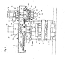
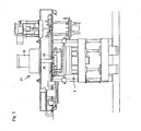
- the casting mold molding machine that is used for this invention has two cylinders 2, 2 that push their arms upward through a machine table 1. Further, guiding rods 3, 3 are installed on the four corners of the machine table 1.
- the piston rods of the two cylinders 2, 2 support a lifting frame 4 at its lower surface, wherein the lifting frame 4 can move up and down and its four corners are slidably provided through the four guiding rods 3, 3.
- the lower mold 6 of a horizontal split-type mold 5 is set on the upper surface of the lifting frame 4.
- the upper mold 7 of the horizontal split-type mold 5 is located just above the lower mold 6 and supported by four supporting pieces of equipment 8, 8 that are installed on the upper side of the lower mold 6 through the guiding rods 3, 3.
- the guiding rods 3, 3 support a ceiling-frame 9, which extends horizontally.
- a mixture-storage means 10 that also acts as a vessel for stirring and as a cylinder for injections is provided on the lower-right side of the ceiling-frame 9 so that the No.1 dolly 11 can move it to the left side of the ceiling-frame 9.
- the mixture-storage means 10 comprises a hollow cube 12 that has a hollow that vertically runs through it, and a bottom plate 14 that is fixed at the bottom of the hollow cube 12 to close it and that has openings for injections 13, 13 through which the mixture is injected.
- the bottom plate 14 has a water-cooled structure on its upper portion and a heat shielded structure on its bottom.
- a mechanism of agitating blades 15 is provided on the upper-right side of the ceiling-frame 9.
- the mechanism mixes particulate aggregate, a water-dispersed binder that is soluble at ambient temperatures, and water, which are all put in the mixture-storage means. Then the agitating blades agitate the mixture and cause it to foam.
- the particulate aggregate may be silica sand, for example.
- the water-dispersed binder that is used for the binder of the particulate aggregate may be polyvinyl alcohol.
- the mechanism of the agitating blades 15 has agitating blades 16 that are connected to the output shaft of a motor 17 through a transmission gear 18.
- the motor 17 is set on a support 20 that moves up and down with the expansion and contraction of a cylinder 19.
- the support 20 has a cover 21 that covers the opening at the upper end of the mixture-storage means 10.
- the agitating blades 16 and the cover 21 move up and down with the expansion and contraction of the cylinder 19.
- a plug means 22 is furnished on the ceiling-frame 9 just under the mechanism of the agitating blades 15.
- the plug means 22 plugs the openings for injections 13, 13 of the mixture-storage means 10.
- the plug means 22 has plugs 23, 23 that can be inserted in the openings for injections 13, 13 and are fixed on a supporting plate 24, which is in turn fixed on the upper end of a cylinder 25 that extends upward.
- the plugs 23, 23 move up and down with the expansion and contraction of a cylinder 25.
- the cylinder 25 is fixed on the ceiling-frame 9 by supports 26, 26.
- the openings for injections 13, 13 may be cleaned by inserting a plurality of plugs 23, 23 into them.
- a push-out-mechanism 27 is provided on the ceiling-frame 9 just above the horizontal split-type mold 5.
- the push-out-mechanism 27 pushes the mixture in the mixture-storage means 10 to inject it through the openings for injections 13, 13.
- the push-out-mechanism 27 comprises a piston 29 that has a plurality of exhaust openings and moves up and down with the expansion and contraction of a cylinder 30 that is installed so as to extend downward.
- a casting mold push-out- mechanism 31 is furnished on the lower left side of the ceiling-frame 9 so that it can be moved rightward by No. 2 dolly 32.
- the casting mold push-out-mechanism 31 pushes a casting mold of the upper mold 7.
- the casting mold push-out-mechanism 31 comprises a push plate 34 that is fixed on the lower end of the cylinder 35 that extends downward.
- the push plate 34 has a plurality of casting mold push-out-pins 33.
- the casting mold push-out-pins 33, 33 move up and down with the expansion and contraction of the cylinder 35.
- this invention monitors and controls the condition of the expandable mixture before injecting it into the mold.
- a casting mold is made by injecting the expandable mixture into the cavity of a heated mold using the casting mold molding machine.
- this invention measures the temperature of an expandable mixture, and then determines each reference value of the one or more characteristic parameters that show the characteristic property of the expandable mixture based on the measured temperature according to the predetermined characteristic property of the expandable mixture (which depends on its moisture content, its viscosity, the type and the particle size of the sand, and the type and the quantity of the binder).
- the characteristic parameter may be its moisture content or its viscosity.
- each determined parameter i.e., the value of its moisture content or its viscosity
- the reference values e.g., within an upper threshold and a minimum threshold of the reference values
- the expandable mixture After that, it is determined whether the expandable mixture is in a normal condition or if it should be adjusted. Depending on the determination, if the expandable mixture is in a normal condition, i.e., each of the measured parameters is judged to be within the corresponding reference value, the expandable mixture will be injected into the cavity of the heated mold and a casting mold will be made. In contrast, if each of the measured parameters of the expandable mixture is judged not to be within the corresponding reference value then, after adjusting the components related to the viscosity and/or the moisture content, the condition of the expandable mixture will again be monitored.
- the temperature, the viscosity, and the moisture content of the expandable mixture are respectively measured by the temperature sensor, the viscosity detector, and the moisture analyzer, which are all installed inside or outside of the mixture storage means.
- the temperature, etc. may also be measured in a batch process by sampling the expandable mixture from the mixture storage means, or in a continuous process by installing the measuring equipment in the mixture storage means.
- the reference value of the viscosity should be 0.5 - 5 Pa ⁇ s and the reference value of the moisture content should be 2 - 10 wt%, if the temperature of the sand is 0 - 40°C, for example.
- This example used silica sand as the particulate aggregate, and polyvinyl alcohol (made by Japan Vam & Poval Co. Ltd.) and a starch (dextrin NSD-L made by Nissi & Co., Ltd.) as water-dispersed binders. 100 parts by weight of silica sand (Flattery sand), 0.2 part by weight of a polyvinyl alcohol, 0.8 part by weight of starch, 0.2 part by weight of a citric acid, and 5 parts by weight of water, were mixed, agitated, and foamed so that the viscosity was 2 Pa ⁇ s and the moisture content was 4.5 wt%. The temperature was 20 °C.
- a plug means 22 for example, silica sand as the particulate aggregate, polyvinyl alcohol as a water-dispersed binder, and water, are put in the mixture storage means 10. Then, the opening on its top end is closed by a cover 21.
- a motor 17 of a mechanism for agitating blades 15 is operated and agitating blades 16 are rotated to mix and agitate the silica sand, the polyvinyl alcohol, and water, and so a foamed expandable mixture is made.
- a cylinder 19 pulls its arm in to raise the agitating blades 16 and cover 21.
- the property of the expandable mixture is confirmed to be in a normal condition by controlling a temperature sensor D1, a viscosity detector D2, and a moisture analyzer D3, and then a cylinder 25 of a plug means 22 pulls its arm in and pulls plugs 23, 23 out from the openings for injections 13, 13 so as to open the openings for injections 13, 13.
- the casting mold push-out-mechanism 31 is moved leftward by a No. 2 dolly 32, and the mixture storage means 10 is also moved leftward by a No. 1 dolly 11, which is located just above the heated horizontal split-type mold 5.
- the cylinder 2 pushes its arm out to raise the lower mold 6 with the lifting frame 4 and to put the upper mold 7 on the lower mold 6 and to put the mixture storage means 10 on the upper mold 7 and to make the lower end of the mixture storage means 10 contact the upper end of the upper mold 7.
- the cylinder 30 of the push-out-mechanism 27 pushes its arm to let down the piston 29.
- the openings of the upper ends of the exhaust ports 28, 28 are closed by valve means, which are not shown, and then the mixture in the mixture storage means 10 is pressed to be injected in the cavity of the horizontal split-type mold 5.
- the mixture that has been injected in it is hardened, because the moisture is evaporated by the heat of the horizontal split-type mold 5.
- the cylinder 30 pulls in its arm to raise the piston 29, and then the casting mold push-out-mechanism 31 is moved rightward by a No. 2 dolly 32, and the mixture storage means 10 is also moved rightward by No. 1 dolly 11 so that the casting mold push-out-mechanism 31 returns to the position just above the horizontal split-type mold 5 and the mixture storage means 10 returns to the position just under the mechanism of the agitating blades 15.
- the cylinder 35 of the casting mold push-out-mechanism 31 pushes its arm to insert the casting mold push-out-pins 33, 33 in the upper mold 7. Then the cylinders 2, 2 pull their arms in to let down the lower mold 6 so that the casting mold is separated from the upper mold 7. After that, a casting mold push-out-mechanism, which is not shown, pushes the casting mold up from the lower mold 6. Meanwhile, silica sand, polyvinyl alcohol, and water are put in the mixture storage means 10, which has returned to the position just under the mechanism of the agitating blades 15, as required for the next molding.
- the mixture in the mixture storage means 10 was injected in the horizontal split-type mold 5 by the piston 29 of the push-out-mechanism 27.
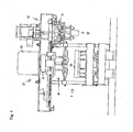
- the method for the injection of the mixture is not restricted to this, but, as in Fig. 4 , a method wherein the mixture is injected by compressed air may achieve the same effect.
- a cover 42 that air-tightly closes the opening of the upper end of the mixture storage means 10 and communicates with a source of compressed air may be installed at the lower end of the piston rod of a cylinder 43 in the push-out-mechanism 27.
- compressed air may be supplied to the upper surface of the mixture in the mixture storage means 10.
- the agitation mechanism and the injection mechanism of compressed air may be combined.
Landscapes
- Engineering & Computer Science (AREA)
- Mechanical Engineering (AREA)
- Mold Materials And Core Materials (AREA)
- Molds, Cores, And Manufacturing Methods Thereof (AREA)
Claims (8)
- Verfahren zur Steuerung eines expansionsfähigen Gemisches, um dieses in einen vorbestimmten Mischzustand zu bringen, wenn eine Gießform hergestellt wird, indem das expansionsfähige Gemisch in einen erwärmten Hohlraum einer Form eingespritzt wird, wobei das expansionsfähige Gemisch durch Mischen von teilchenförmigem Aggregat, einem in Wasser dispergierten Bindemittel sowie Wasser gebildet wird, wobei das Verfahren folgende Schritte aufweist:(a) Messen der Temperatur des expansionsfähigen Gemisches,(b) Bestimmen von Referenzwerten des Feuchtigkeitsgehalts und der Viskosität, die eine charakteristische Eigenschaft des expansionsfähigen Gemisches zeigen, auf der Basis der gemessenen Temperatur und des vorbestimmten Mischzustands, in dem das expansionsfähige Gemisch zum Herstellen einer Gießform in den Hohlraum eingespritzt werden kann, wobei der Zustand der Temperatur des Gemisches entspricht,(c) Messen des Feuchtigkeitsgehalts des expansionsfähigen Gemisches, der den Mischzustand von diesem zeigt,(d) Feststellen, ob der gemessene Feuchtigkeitsgehalt innerhalb von dessen Referenzwert liegt,(e) Messen der Viskosität des expansionsfähigen Gemisches, um festzustellen, ob der gemessene Feuchtigkeitsgehalt innerhalb von dessen Referenzwert liegt,(f) Feststellen, ob die gemessene Viskosität innerhalb von deren Referenzwert liegt, und(g) Feststellen, dass das expansionsfähige Gemisch in dem Mischzustand vorliegt, in dem das expansionsfähige Gemisch in den Hohlraum eingespritzt werden kann, wenn die gemessene Viskosität als innerhalb von deren Referenzwert liegend festgestellt wird.
- Verfahren zur Steuerung eines expansionsfähigen Gemisches nach Anspruch 1, wobei es ferner einen Schritt aufweist, in dem jegliches fehlende Wasser zugegeben und das expansionsfähige Gemisch erneut gemischt wird, wenn der gemessene Feuchtigkeitsgehalt nicht innerhalb des Referenzwerts von diesem liegt.
- Verfahren zur Steuerung eines expansionsfähigen Gemisches nach Anspruch 1 oder 2,
wobei es ferner einen Schritt aufweist, in dem das expansionsfähige Gemisch erneut gemischt wird, wenn die gemessene Viskosität nicht innerhalb von deren Referenzwert liegt. - Verfahren zur Steuerung eines expansionsfähigen Gemisches nach Anspruch 3, wobei die Temperatur des expansionsfähigen Gemisches entweder mittels einer Temperaturerfassungseinrichtung vom Berührungstyp oder mittels einer Temperaturerfassungseinrichtung vom berührungslosen Typ gemessen wird.
- Verfahren zur Steuerung eines expansionsfähigen Gemisches nach Anspruch 3, wobei der Feuchtigkeitsgehalt des expansionsfähigen Gemisches entweder mittels eines Verfahrens zum Messen eines elektrischen Widerstands von diesem oder mittels eines Mikrowellen verwendenden Verfahrens gemessen wird.
- Verfahren zur Steuerung eines expansionsfähigen Gemisches nach Anspruch 3, wobei die Viskosität des expansionsfähigen Gemisches mittels einer Viskositäts-Messeinrichtung, die ein Sondeneinführverfahren verwendet, einer Viskositäts-Messeinrichtung, die ein Sondenrotationsverfahren verwendet, oder einer Viskositäts-Messeinrichtung, die ein Sondeneinführ- und Sondenrotationsverfahren verwendet, gemessen wird.
- Verfahren zur Steuerung eines expansionsfähigen Gemisches nach Anspruch 3, wobei der Feuchtigkeitsgehalt und die Viskosität des expansionsfähigen Gemisches in einem chargenweisen Prozess gemessen werden, indem eine Probe des expansionsfähigen Gemisches von einer Gemisch-Lagereinrichtung für das expansionsfähige Gemisch entnommen wird.
- Verfahren zur Steuerung eines expansionsfähigen Gemisches nach Anspruch 3, wobei die Temperatur, der Feuchtigkeitsgehalt und die Viskosität des expansionsfähigen Gemisches in einem kontinuierlichen Prozess gemessen werden, indem die Messeinrichtung in einer Gemisch-Lagereinrichtung für das expansionsfähige Gemisch installiert wird.
Applications Claiming Priority (2)
| Application Number | Priority Date | Filing Date | Title |
|---|---|---|---|
| JP2005174520 | 2005-06-15 | ||
| PCT/JP2006/311620 WO2006134841A1 (ja) | 2005-06-15 | 2006-06-09 | 発泡性混合物の管理方法 |
Publications (3)
| Publication Number | Publication Date |
|---|---|
| EP1897633A1 EP1897633A1 (de) | 2008-03-12 |
| EP1897633A4 EP1897633A4 (de) | 2009-07-22 |
| EP1897633B1 true EP1897633B1 (de) | 2011-08-17 |
Family
ID=37532204
Family Applications (1)
| Application Number | Title | Priority Date | Filing Date |
|---|---|---|---|
| EP06766532A Expired - Lifetime EP1897633B1 (de) | 2005-06-15 | 2006-06-09 | Verfahren zur steuerung eines schäumenden gemisches |
Country Status (7)
| Country | Link |
|---|---|
| US (1) | US7766543B2 (de) |
| EP (1) | EP1897633B1 (de) |
| JP (1) | JP4238932B2 (de) |
| KR (1) | KR101051494B1 (de) |
| CN (1) | CN101242919B (de) |
| AU (1) | AU2006258744A1 (de) |
| WO (1) | WO2006134841A1 (de) |
Families Citing this family (8)
| Publication number | Priority date | Publication date | Assignee | Title |
|---|---|---|---|---|
| JP5840082B2 (ja) * | 2012-06-25 | 2016-01-06 | 新東工業株式会社 | 発泡混練物の造型装置及び発泡混練物の造型方法 |
| JP5958966B2 (ja) * | 2013-03-25 | 2016-08-02 | トヨタ自動車株式会社 | 造型装置および造型方法 |
| JP6558858B2 (ja) * | 2016-04-08 | 2019-08-14 | 新東工業株式会社 | 混練機構、造型装置及び発泡混合物の製造方法 |
| JP6470243B2 (ja) * | 2016-10-31 | 2019-02-13 | トヨタ自動車株式会社 | 中子造形装置及び中子造形方法 |
| JP6822315B2 (ja) * | 2017-05-19 | 2021-01-27 | 新東工業株式会社 | 鋳型造型装置及び鋳型造型方法 |
| CN107186947A (zh) * | 2017-05-26 | 2017-09-22 | 太仓巨洲塑料科技有限公司 | 一种高精准性智能化可调式板机及其工作方法 |
| CN107088985A (zh) * | 2017-05-26 | 2017-08-25 | 太仓巨洲塑料科技有限公司 | 一种高精度智能化可移动式发泡成型设备及其工作方法 |
| JP7230871B2 (ja) * | 2020-03-19 | 2023-03-01 | 新東工業株式会社 | 鋳型造型方法 |
Family Cites Families (12)
| Publication number | Priority date | Publication date | Assignee | Title |
|---|---|---|---|---|
| GB1200507A (en) | 1968-02-16 | 1970-07-29 | British Motor Corp Ltd | Production of foundry cores |
| GB1402536A (en) * | 1971-08-13 | 1975-08-13 | Nat Res Dev | Methods and apparatus for the measurement of viscosity |
| SU702603A1 (ru) * | 1978-08-31 | 1981-12-23 | Центральное Проектно-Конструкторское И Технологическое Бюро Главсантехпром Минстройматериалов Ссср | Установка дл изготовлени стержней |
| JPS564342A (en) | 1979-06-26 | 1981-01-17 | Daiwa Seisakusho:Kk | Mold molding method and its device |
| US5028367A (en) * | 1988-08-15 | 1991-07-02 | Rensselaer Polytechnic Institute | Two-stage fast debinding of injection molding powder compacts |
| JP3346715B2 (ja) * | 1997-01-17 | 2002-11-18 | 新東工業株式会社 | 生砂造型の充填不良の予測方法 |
| JP3223503B2 (ja) | 1997-02-14 | 2001-10-29 | 新東工業株式会社 | 混練砂のc/b値コントロールシステム |
| JP2000190049A (ja) * | 1998-12-24 | 2000-07-11 | Sintokogio Ltd | 鋳型の造型方法 |
| CN1175948C (zh) * | 2000-06-13 | 2004-11-17 | 秦升益 | 复合制型、芯工艺和装置 |
| US6635099B2 (en) * | 2001-01-24 | 2003-10-21 | Rutgers, The State University Of New Jersey | Aqueous nonferrous feedstock material for injection molding |
| EA008841B1 (ru) * | 2004-03-23 | 2007-08-31 | Синтокогио, Лтд. | Устройство для формирования пресс-формы и используемая в нем металлическая пресс-форма |
| US7721649B2 (en) * | 2007-09-17 | 2010-05-25 | Baker Hughes Incorporated | Injection molded shaped charge liner |
-
2006
- 2006-06-09 WO PCT/JP2006/311620 patent/WO2006134841A1/ja not_active Ceased
- 2006-06-09 US US11/921,956 patent/US7766543B2/en active Active
- 2006-06-09 JP JP2007521265A patent/JP4238932B2/ja not_active Expired - Lifetime
- 2006-06-09 EP EP06766532A patent/EP1897633B1/de not_active Expired - Lifetime
- 2006-06-09 KR KR1020087000953A patent/KR101051494B1/ko not_active Expired - Fee Related
- 2006-06-09 CN CN2006800295783A patent/CN101242919B/zh not_active Expired - Lifetime
- 2006-06-09 AU AU2006258744A patent/AU2006258744A1/en not_active Abandoned
Also Published As
| Publication number | Publication date |
|---|---|
| EP1897633A4 (de) | 2009-07-22 |
| AU2006258744A1 (en) | 2006-12-21 |
| US7766543B2 (en) | 2010-08-03 |
| JP4238932B2 (ja) | 2009-03-18 |
| CN101242919A (zh) | 2008-08-13 |
| WO2006134841A1 (ja) | 2006-12-21 |
| KR20080021781A (ko) | 2008-03-07 |
| US20090092171A1 (en) | 2009-04-09 |
| JPWO2006134841A1 (ja) | 2009-01-08 |
| EP1897633A1 (de) | 2008-03-12 |
| CN101242919B (zh) | 2010-12-22 |
| KR101051494B1 (ko) | 2011-07-22 |
Similar Documents
| Publication | Publication Date | Title |
|---|---|---|
| EP1749598B1 (de) | Vorrichtung zur herstellung einer gussform und metallformeinheit für den einsatz darin | |
| US7766543B2 (en) | Method for controlling an expandable mixture | |
| JPS59163537A (ja) | 諸特性の測定に用いる鋳型材混合物の試験片の製造方法及び装置 | |
| JP5958966B2 (ja) | 造型装置および造型方法 | |
| US4145143A (en) | Method of controlling the properties of a mixture | |
| CN100500327C (zh) | 铸模造型装置以及使用于其上的金属模具装置 | |
| CN107848019B (zh) | 混炼机构、造型装置以及发泡混合物的制造方法 | |
| KR100491151B1 (ko) | 최적의압분성을이용하여주물사를조절하기위한방법및장치 | |
| JP4337933B2 (ja) | 発泡骨材混合物の管理方法 | |
| MX2007015987A (es) | Metodo para controlar una mezcla espumosa. | |
| EP2716384A1 (de) | Verfahren zur herstellung von formsand und vorrichtung zur durchführung des verfahrens (ausführungen) | |
| CN115570724A (zh) | 溶液混合浇注方法以及溶液混合浇注装置 | |
| CN223362077U (zh) | 一种聚氨酯发泡实验装置 | |
| JP2023009523A (ja) | 温度制御方法および成型装置 | |
| MXPA06010878A (en) | Casting mold forming apparatus and metal mold unit for use therein | |
| JP2577988B2 (ja) | ダイカストマシンの射出装置 | |
| JP2025024483A (ja) | 鋳物砂の検査方法及び検査装置 | |
| Bedo | EXPERIMENTAL RESEARCH ON THE INFLUENCE OF PLASTER/SAND RATIO AND WATER CONTENT ON THE POROSITY OF THE PLASTER MOLDS |
Legal Events
| Date | Code | Title | Description |
|---|---|---|---|
| PUAI | Public reference made under article 153(3) epc to a published international application that has entered the european phase |
Free format text: ORIGINAL CODE: 0009012 |
|
| 17P | Request for examination filed |
Effective date: 20071210 |
|
| AK | Designated contracting states |
Kind code of ref document: A1 Designated state(s): AT BE BG CH CY CZ DE DK EE ES FI FR GB GR HU IE IS IT LI LT LU LV MC NL PL PT RO SE SI SK TR |
|
| DAX | Request for extension of the european patent (deleted) | ||
| DAX | Request for extension of the european patent (deleted) | ||
| A4 | Supplementary search report drawn up and despatched |
Effective date: 20090622 |
|
| 17Q | First examination report despatched |
Effective date: 20091030 |
|
| RIC1 | Information provided on ipc code assigned before grant |
Ipc: B22C 5/14 20060101ALI20101021BHEP Ipc: B22C 9/00 20060101AFI20101021BHEP |
|
| GRAP | Despatch of communication of intention to grant a patent |
Free format text: ORIGINAL CODE: EPIDOSNIGR1 |
|
| GRAS | Grant fee paid |
Free format text: ORIGINAL CODE: EPIDOSNIGR3 |
|
| GRAA | (expected) grant |
Free format text: ORIGINAL CODE: 0009210 |
|
| AK | Designated contracting states |
Kind code of ref document: B1 Designated state(s): AT BE BG CH CY CZ DE DK EE ES FI FR GB GR HU IE IS IT LI LT LU LV MC NL PL PT RO SE SI SK TR |
|
| REG | Reference to a national code |
Ref country code: GB Ref legal event code: FG4D |
|
| REG | Reference to a national code |
Ref country code: CH Ref legal event code: EP |
|
| REG | Reference to a national code |
Ref country code: IE Ref legal event code: FG4D |
|
| REG | Reference to a national code |
Ref country code: DE Ref legal event code: R096 Ref document number: 602006023861 Country of ref document: DE Effective date: 20111027 |
|
| REG | Reference to a national code |
Ref country code: NL Ref legal event code: VDEP Effective date: 20110817 |
|
| LTIE | Lt: invalidation of european patent or patent extension |
Effective date: 20110817 |
|
| PG25 | Lapsed in a contracting state [announced via postgrant information from national office to epo] |
Ref country code: PT Free format text: LAPSE BECAUSE OF FAILURE TO SUBMIT A TRANSLATION OF THE DESCRIPTION OR TO PAY THE FEE WITHIN THE PRESCRIBED TIME-LIMIT Effective date: 20111219 Ref country code: LT Free format text: LAPSE BECAUSE OF FAILURE TO SUBMIT A TRANSLATION OF THE DESCRIPTION OR TO PAY THE FEE WITHIN THE PRESCRIBED TIME-LIMIT Effective date: 20110817 Ref country code: SE Free format text: LAPSE BECAUSE OF FAILURE TO SUBMIT A TRANSLATION OF THE DESCRIPTION OR TO PAY THE FEE WITHIN THE PRESCRIBED TIME-LIMIT Effective date: 20110817 Ref country code: NL Free format text: LAPSE BECAUSE OF FAILURE TO SUBMIT A TRANSLATION OF THE DESCRIPTION OR TO PAY THE FEE WITHIN THE PRESCRIBED TIME-LIMIT Effective date: 20110817 Ref country code: IS Free format text: LAPSE BECAUSE OF FAILURE TO SUBMIT A TRANSLATION OF THE DESCRIPTION OR TO PAY THE FEE WITHIN THE PRESCRIBED TIME-LIMIT Effective date: 20111217 Ref country code: FI Free format text: LAPSE BECAUSE OF FAILURE TO SUBMIT A TRANSLATION OF THE DESCRIPTION OR TO PAY THE FEE WITHIN THE PRESCRIBED TIME-LIMIT Effective date: 20110817 |
|
| REG | Reference to a national code |
Ref country code: AT Ref legal event code: MK05 Ref document number: 520483 Country of ref document: AT Kind code of ref document: T Effective date: 20110817 |
|
| PG25 | Lapsed in a contracting state [announced via postgrant information from national office to epo] |
Ref country code: CY Free format text: LAPSE BECAUSE OF FAILURE TO SUBMIT A TRANSLATION OF THE DESCRIPTION OR TO PAY THE FEE WITHIN THE PRESCRIBED TIME-LIMIT Effective date: 20110817 Ref country code: SI Free format text: LAPSE BECAUSE OF FAILURE TO SUBMIT A TRANSLATION OF THE DESCRIPTION OR TO PAY THE FEE WITHIN THE PRESCRIBED TIME-LIMIT Effective date: 20110817 Ref country code: LV Free format text: LAPSE BECAUSE OF FAILURE TO SUBMIT A TRANSLATION OF THE DESCRIPTION OR TO PAY THE FEE WITHIN THE PRESCRIBED TIME-LIMIT Effective date: 20110817 Ref country code: AT Free format text: LAPSE BECAUSE OF FAILURE TO SUBMIT A TRANSLATION OF THE DESCRIPTION OR TO PAY THE FEE WITHIN THE PRESCRIBED TIME-LIMIT Effective date: 20110817 Ref country code: GR Free format text: LAPSE BECAUSE OF FAILURE TO SUBMIT A TRANSLATION OF THE DESCRIPTION OR TO PAY THE FEE WITHIN THE PRESCRIBED TIME-LIMIT Effective date: 20111118 Ref country code: PL Free format text: LAPSE BECAUSE OF FAILURE TO SUBMIT A TRANSLATION OF THE DESCRIPTION OR TO PAY THE FEE WITHIN THE PRESCRIBED TIME-LIMIT Effective date: 20110817 |
|
| PG25 | Lapsed in a contracting state [announced via postgrant information from national office to epo] |
Ref country code: BE Free format text: LAPSE BECAUSE OF FAILURE TO SUBMIT A TRANSLATION OF THE DESCRIPTION OR TO PAY THE FEE WITHIN THE PRESCRIBED TIME-LIMIT Effective date: 20110817 |
|
| PG25 | Lapsed in a contracting state [announced via postgrant information from national office to epo] |
Ref country code: SK Free format text: LAPSE BECAUSE OF FAILURE TO SUBMIT A TRANSLATION OF THE DESCRIPTION OR TO PAY THE FEE WITHIN THE PRESCRIBED TIME-LIMIT Effective date: 20110817 |
|
| PG25 | Lapsed in a contracting state [announced via postgrant information from national office to epo] |
Ref country code: RO Free format text: LAPSE BECAUSE OF FAILURE TO SUBMIT A TRANSLATION OF THE DESCRIPTION OR TO PAY THE FEE WITHIN THE PRESCRIBED TIME-LIMIT Effective date: 20110817 Ref country code: EE Free format text: LAPSE BECAUSE OF FAILURE TO SUBMIT A TRANSLATION OF THE DESCRIPTION OR TO PAY THE FEE WITHIN THE PRESCRIBED TIME-LIMIT Effective date: 20110817 |
|
| PLBE | No opposition filed within time limit |
Free format text: ORIGINAL CODE: 0009261 |
|
| STAA | Information on the status of an ep patent application or granted ep patent |
Free format text: STATUS: NO OPPOSITION FILED WITHIN TIME LIMIT |
|
| PG25 | Lapsed in a contracting state [announced via postgrant information from national office to epo] |
Ref country code: DK Free format text: LAPSE BECAUSE OF FAILURE TO SUBMIT A TRANSLATION OF THE DESCRIPTION OR TO PAY THE FEE WITHIN THE PRESCRIBED TIME-LIMIT Effective date: 20110817 |
|
| 26N | No opposition filed |
Effective date: 20120521 |
|
| REG | Reference to a national code |
Ref country code: DE Ref legal event code: R097 Ref document number: 602006023861 Country of ref document: DE Effective date: 20120521 |
|
| PG25 | Lapsed in a contracting state [announced via postgrant information from national office to epo] |
Ref country code: MC Free format text: LAPSE BECAUSE OF NON-PAYMENT OF DUE FEES Effective date: 20120630 |
|
| REG | Reference to a national code |
Ref country code: CH Ref legal event code: PL |
|
| REG | Reference to a national code |
Ref country code: CH Ref legal event code: PL |
|
| REG | Reference to a national code |
Ref country code: IE Ref legal event code: MM4A |
|
| PG25 | Lapsed in a contracting state [announced via postgrant information from national office to epo] |
Ref country code: CH Free format text: LAPSE BECAUSE OF NON-PAYMENT OF DUE FEES Effective date: 20120630 Ref country code: LI Free format text: LAPSE BECAUSE OF NON-PAYMENT OF DUE FEES Effective date: 20120630 Ref country code: ES Free format text: LAPSE BECAUSE OF FAILURE TO SUBMIT A TRANSLATION OF THE DESCRIPTION OR TO PAY THE FEE WITHIN THE PRESCRIBED TIME-LIMIT Effective date: 20111128 Ref country code: IE Free format text: LAPSE BECAUSE OF NON-PAYMENT OF DUE FEES Effective date: 20120609 |
|
| PG25 | Lapsed in a contracting state [announced via postgrant information from national office to epo] |
Ref country code: BG Free format text: LAPSE BECAUSE OF FAILURE TO SUBMIT A TRANSLATION OF THE DESCRIPTION OR TO PAY THE FEE WITHIN THE PRESCRIBED TIME-LIMIT Effective date: 20111117 |
|
| PG25 | Lapsed in a contracting state [announced via postgrant information from national office to epo] |
Ref country code: TR Free format text: LAPSE BECAUSE OF FAILURE TO SUBMIT A TRANSLATION OF THE DESCRIPTION OR TO PAY THE FEE WITHIN THE PRESCRIBED TIME-LIMIT Effective date: 20110817 |
|
| PG25 | Lapsed in a contracting state [announced via postgrant information from national office to epo] |
Ref country code: LU Free format text: LAPSE BECAUSE OF NON-PAYMENT OF DUE FEES Effective date: 20120609 |
|
| PG25 | Lapsed in a contracting state [announced via postgrant information from national office to epo] |
Ref country code: HU Free format text: LAPSE BECAUSE OF FAILURE TO SUBMIT A TRANSLATION OF THE DESCRIPTION OR TO PAY THE FEE WITHIN THE PRESCRIBED TIME-LIMIT Effective date: 20060609 |
|
| REG | Reference to a national code |
Ref country code: FR Ref legal event code: PLFP Year of fee payment: 11 |
|
| REG | Reference to a national code |
Ref country code: FR Ref legal event code: PLFP Year of fee payment: 12 |
|
| REG | Reference to a national code |
Ref country code: FR Ref legal event code: PLFP Year of fee payment: 13 |
|
| PGFP | Annual fee paid to national office [announced via postgrant information from national office to epo] |
Ref country code: FR Payment date: 20230627 Year of fee payment: 18 Ref country code: CZ Payment date: 20230606 Year of fee payment: 18 |
|
| PGFP | Annual fee paid to national office [announced via postgrant information from national office to epo] |
Ref country code: IT Payment date: 20230623 Year of fee payment: 18 Ref country code: GB Payment date: 20230620 Year of fee payment: 18 |
|
| PG25 | Lapsed in a contracting state [announced via postgrant information from national office to epo] |
Ref country code: CZ Free format text: LAPSE BECAUSE OF NON-PAYMENT OF DUE FEES Effective date: 20240609 |
|
| PG25 | Lapsed in a contracting state [announced via postgrant information from national office to epo] |
Ref country code: CZ Free format text: LAPSE BECAUSE OF NON-PAYMENT OF DUE FEES Effective date: 20240609 |
|
| GBPC | Gb: european patent ceased through non-payment of renewal fee |
Effective date: 20240609 |
|
| PG25 | Lapsed in a contracting state [announced via postgrant information from national office to epo] |
Ref country code: FR Free format text: LAPSE BECAUSE OF NON-PAYMENT OF DUE FEES Effective date: 20240630 |
|
| PG25 | Lapsed in a contracting state [announced via postgrant information from national office to epo] |
Ref country code: GB Free format text: LAPSE BECAUSE OF NON-PAYMENT OF DUE FEES Effective date: 20240609 Ref country code: IT Free format text: LAPSE BECAUSE OF NON-PAYMENT OF DUE FEES Effective date: 20240609 |
|
| PGFP | Annual fee paid to national office [announced via postgrant information from national office to epo] |
Ref country code: DE Payment date: 20250618 Year of fee payment: 20 |
|
| REG | Reference to a national code |
Ref country code: DE Ref legal event code: R071 Ref document number: 602006023861 Country of ref document: DE |