EP1897844A2 - Réception de charge pour un dispositif de levage - Google Patents
Réception de charge pour un dispositif de levage Download PDFInfo
- Publication number
- EP1897844A2 EP1897844A2 EP07016781A EP07016781A EP1897844A2 EP 1897844 A2 EP1897844 A2 EP 1897844A2 EP 07016781 A EP07016781 A EP 07016781A EP 07016781 A EP07016781 A EP 07016781A EP 1897844 A2 EP1897844 A2 EP 1897844A2
- Authority
- EP
- European Patent Office
- Prior art keywords
- load
- cross member
- bearing according
- receiving
- receiving element
- Prior art date
- Legal status (The legal status is an assumption and is not a legal conclusion. Google has not performed a legal analysis and makes no representation as to the accuracy of the status listed.)
- Granted
Links
Images
Classifications
-
- B—PERFORMING OPERATIONS; TRANSPORTING
- B66—HOISTING; LIFTING; HAULING
- B66F—HOISTING, LIFTING, HAULING OR PUSHING, NOT OTHERWISE PROVIDED FOR, e.g. DEVICES WHICH APPLY A LIFTING OR PUSHING FORCE DIRECTLY TO THE SURFACE OF A LOAD
- B66F3/00—Devices, e.g. jacks, adapted for uninterrupted lifting of loads
- B66F3/24—Devices, e.g. jacks, adapted for uninterrupted lifting of loads fluid-pressure operated
- B66F3/25—Constructional features
- B66F3/36—Load-engaging elements
-
- B—PERFORMING OPERATIONS; TRANSPORTING
- B66—HOISTING; LIFTING; HAULING
- B66F—HOISTING, LIFTING, HAULING OR PUSHING, NOT OTHERWISE PROVIDED FOR, e.g. DEVICES WHICH APPLY A LIFTING OR PUSHING FORCE DIRECTLY TO THE SURFACE OF A LOAD
- B66F7/00—Lifting frames, e.g. for lifting vehicles; Platform lifts
- B66F7/28—Constructional details, e.g. end stops, pivoting supporting members, sliding runners adjustable to load dimensions
Definitions
- the invention relates to a load receiving device for a lifting device according to the preamble of claim 1.
- a lifting device in particular mobile lifting device, known, which is intended for lifting loads, vehicles or the like.
- This lifting device comprises a base frame, which is preferably equipped with a steering gear.
- a lifting unit is provided, which comprises a lifting column, in which a drive unit is arranged.
- a load pickup is transferred from a rest position to a working position.
- a control unit is provided, which is connected by supply lines with a further lifting device or a central control unit.
- the load bearing on the lifting device comprises a cross member, on the two Load-receiving elements or wheel gripping elements are arranged. To secure the set position it is necessary to attach a screw connection with a tool. This arrangement requires a tool for adjusting the load-bearing elements.
- the load-bearing elements can alternatively be secured in their load-receiving position by plug-in pins.
- plug-in pins Such an embodiment has the disadvantage that the locking pins themselves require an additional safeguard against self-loosening and during the change of the position of the load fork such locking pins can be lost.
- the invention is therefore an object of the invention to provide a load bearing, which allows a simple and rapid change of the load receiving position of the load-bearing element is made possible to the cross member.
- the load-receiving element from and into a secure load-receiving position can be transferred.
- This allows rapid adjustment of a desired position of the load-bearing element on the cross member.
- the load-receiving element along the cross member can be changed in position.
- the load-receiving element is converted by a reversal of the pivoting movement in a secure load-receiving position.
- the aid of tools is not required.
- an additional assembly and disassembly of plug and / or fuse elements is not required, which does not allow proper handling of the load-receiving position in case of improper handling.
- the load-receiving means and the cross member each have at least one holding element, which engage in a secure load-receiving position in a form-fitting manner.
- the holding elements are fixedly arranged on the load-receiving element and the cross member and thus captive. Due to the positive engagement, a simple release and when merging an alignment in a provided load-receiving position is made possible, so that a defined position is taken from the load-receiving element to the cross member. By such a positive engagement at least a lateral displacement of the load-receiving element is secured.
- This has the advantage, in particular in the case of a load bearing with fork-shaped wheel gripping elements, that two wheel gripping elements acting on a wheel do not increase their distance from one another and engage securely on the wheel.
- the retaining element of the cross member is formed as an open-edged and U-shaped recess, in which engages formed as a cam holding member of the load-receiving element.
- An advantageous embodiment of the holding elements of the carrier provides that the U-shaped recesses are provided on a lower horizontally extending portion of the cross member and form a position securing area.
- the U-shaped recesses are preferably arranged at regular intervals from each other, so that a grid-shaped adjustment of the distance of two or more load-receiving elements to each other on the cross member is made possible.
- the retaining elements formed as cams on the load-receiving element preferably have side surfaces which are aligned parallel to the long legs of the U-shaped recesses and formed for abutment thereon. This makes it possible that lateral forces can be safely absorbed under load of the load-bearing elements and a displacement of the load-bearing elements is prevented during operation.
- the load-receiving element engages an upper support region of the cross member with a hooking region, which makes it possible for a support section assigned to the position-securing region to be provided opposite to the cross member. As a result, a pivot axis for the load-receiving element is formed on the support area.
- the holding element of the load-receiving element projects with respect to the support section in the direction of the position-securing area.
- a secure engagement is given to the cross member.
- the holding element protrudes by the thickness of the particular plate-shaped cross member, so that between the cam-shaped holding element and the U-shaped orientation is given a sheet-like contact with occurring transverse forces.
- the lift-off advantageously has an L-shaped shape and is a mirror image of the Einitatiwitz the load-bearing element aligned. This makes it possible that the cross member on the support area and position securing area is securely gripped against loosening of cross member and a displacement of the load-receiving element is maintained along the cross member.
- a further partial reduction for the design of a load bearing is preferably given by the fact that the holding element and the anti-lift device are integrally formed.
- the manufacturing process for the lift-off and the retaining element can be reduced from two to one part.
- a simple and fast attachment is possible.
- a distance between the anti-lifting device to the lower edge of the cross member is formed smaller than an engagement depth of the Einitati Foundationes, which engages the upper edge of the cross member.
- the lift-off secures a lifting of the support portion on the load-receiving element of a position securing portion of the cross member such that the holding element is released from the U-shaped recess and the load-receiving element along the cross member is displaceable and further lifting the Supporting section is prevented.
- a short leg of the L-shaped anti-lifting device engages behind the cross member, wherein the distance of the L-shaped engaging portion behind the anti-lifting device and a front side of the holding element are arranged on the load-receiving element at a distance from each other, which corresponds at least to the thickness of the preferably formed as a plate cross member and is only slightly larger, so that a simple shift without entanglement is made possible.
- the pivoting movement of the load-receiving element for transferring into an unsecured load-receiving position for displacing the load-receiving element along the transverse strut is preferably in a range between 0.5 ° and 20 °. As a result, even a slight lifting can be sufficient for the load-receiving element to be released from the secured position. Due to the L-shaped load-receiving element, a lever effect is generated which facilitates operation or lifting.
- the cross member has a releasable locking at the respective outer end of the support area.
- This can be, for example, a screw or clamp connection.
- the load-bearing element can be completely removed from the cross member.
- the load-receiving element is secured in the presence of the lock to the cross member.
- the lifting device is designed as a mobile lifting device together with other lifting devices for lifting multi-axle vehicles.
- the load-bearing forks are preferably designed as right and left load-bearing element and each directed toward each other Recording surfaces on. As a result, a centering of the wheel or other objects for load bearing can be made possible.
- the receiving surface of the load-carrying forks has bores. This allows an improved attack on the wheel. In addition, a reduction in the dead weight of the load-bearing elements can be achieved. Alternatively, the load-bearing surface may also have profilings.
- the load-receiving element has a left and right plate-shaped retaining profile, on each of which a Einitatiwitz is provided for engagement on the support region of the cross member. Due to the design of the plate-shaped retaining profiles of the hanging area can be produced inexpensively by a simple punching or laser machining. By spaced apart left and right retaining profiles a secure support and tilting arrangement of the load-bearing element is given. The Verkippungssteiftechnik is also made possible by the engaging at the lower end of the cross member retaining element for securing the load-receiving element.
- the left and right retaining profile at least by a transverse strut and a footprint and in particular by a spacer element are spaced from each other.
- a simple and rigid support structure can be formed, which is made of individual sheet metal parts.
- Such sheet metal parts can be produced as stamping or laser machining parts. As a result, a lightweight construction is achieved.
- the contact surface is formed as a stamped and bent part, which has a receiving surface and a distance portion unwound therefrom.
- a section of the left and right holding profile of the load-receiving element pointing in the vertical direction and in particular the distance section of the contact surface to the lifting device are inclined and are arranged at an angle greater than 90 ° to the support surface.
- the load-receiving element are arranged by the holding profiles, the cross member and the footprint in an open design with free spaces to each other.
- This open design allows for weight savings and ease of manufacture.
- a hot dip galvanizing can be provided by the open design, without additional openings or recesses are to be introduced into the load-receiving element.
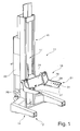
- a lifting device 11 is shown in perspective, which is suitable for mobile use.
- a steering gear 12 is provided on the base frame 14.
- a lifting unit 17 is provided, which comprises an electric, electro-hydraulic, hydraulic or mechanical drive. By this drive, a load bearing 18 is transferred from a lower rest position to a working position 21.
- a control unit 22 is further provided, which is connected via a supply line not shown with an energy source, another lifting device or another control unit.
- the load receiver 18 comprises a cross member 24 on which two load receiving elements 26 are provided according to the embodiment.
- the load-bearing elements 26 are designed as fork-shaped wheel gripping elements, which comprise load-bearing forks 27.
- On these load-carrying forks 27 receiving surfaces 29 are provided, which are oriented toward each other to attack the wheel surface.
- the receiving surfaces 29 have holes 31 and openings, which serve to increase the adhesion to a tire profile and at the same time allow a reduction in weight.
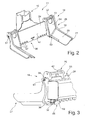
- the load bearing 18 is shown in perspective from the front and back.
- the cross member 24 forms by the upper edge region or the horizontally extending edges, a support portion 33 for the load-receiving element 26.
- This has a hooking 34, which is designed as Einticianhaken or Ein vonklammer, wherein a U-shaped recess formed is, so that the support portion 33 is engaged behind.
- a position securing region 36 for the load-bearing elements 26 is formed at the lower edge.
- This position securing area 36 is formed by a plurality of retaining elements 37, for example, provided as U-shaped recesses, which are preferably arranged at a regular distance from one another.
- the transitions from one to the adjacent holding element 37 are preferably rounded, so that an insertion region is formed in order to facilitate a facilitated engagement of a preferably designed as a cam holding element 38, which is arranged on the load-receiving element 26.
- the holding elements 37 and the holding element 38 form positive-locking holding elements, which enable a secure load-receiving position of the load-receiving element 26 to the cross member 24 according to Figures 2 and 3.
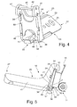
- FIG. 4 shows a perspective view of a load-bearing element 26.
- the suspension area 34 is formed by a right and left retaining profile 41, which are spaced apart by a web 42. Below the web 42, a hanging area 34 is U-shaped on each retaining profile 41. This suspension area 34 is larger than the thickness of the cross member 34 and has an additional free surface 44.
- a support portion 46 is provided in each case, which is formed by the end faces of the holding profiles 41 which abut in a position of use on a side surface 47 of the cross member 24 and are supported. Between the two support portions 46 designed as a cam holding element 38 is disposed on a lower support portion 40 of the load-receiving element 26.
- This section is preferably integrally connected to the retaining profile 41 and manufactured as a sheet metal stamping part or sheet metal cutting part of a material.
- This holding element 38 has side surfaces 49 which bear against the long legs of the holding device 37.
- a for attachment region 34 facing end face 51 of the support member 38 is preferably formed inclined so that in a subsequently described in more detail pivotal movement a faster and easy release of the support member 38 of U-shaped support members 37 is possible.
- the holding member 38 and the Assigned support portion 46 is provided a lift-off 56.
- This lift-off 56 is L-shaped. The function of the lift-off guard 56 will be described in more detail with reference to Figure 5, which shows an unsecured load receiving position of the load-receiving element 26.
- the holding element 38 and the anti-lift device 56 can be combined in one component.
- the geometry of the holding device 38 and the function of the anti-lift device 56 is retained.
- a lug 59 of the lift-off safety device 56 is preferably limited to the width of the holding element 38, preferably to the width of the end face 51 of the holding element 38. The function and safety are retained. This can be given a further simplification in the production, since the lift-off 56 and the holding member 38 are made as a sheet metal stamping or sheet metal cutting part of a material.
- the holding element 38 engages the load-receiving elements 26 in the holding member 37 of the cross member 24 a.
- the load-receiving element 26 is secured against tilting by transverse forces.
- a displacement of the load-receiving element 26 along the cross member 24 is prevented.
- the lift-off protection 56 acts in such a way that a distance between the lift-off safety device 56 and the lower edge of the cross member 24 is less than an engagement depth of the hanging region 34.
- a distance between an end face 57 pointing to the cross member and the substantially parallel aligned tab 59 of the anti-lifting device is spaced such that at least the wall thickness of the cross member 24 is encompassed.
- a latch 61 is provided at the respective outer upper end of the cross member 34.
- This lock 31 secures the load-bearing element or elements 26 to the cross member 24.
- the lock 61 is preferably detachable to replace the load-receiving elements 26.
- the load-bearing element 16 shown in FIGS. 1 to 5 has an open design through the individual sheet-metal parts, which are produced as stamped, bent-stamped or laser-processed parts. Such an open design leads to a lightweight construction, at the same time given the stability for load bearing. At the same time a cost reduction can be achieved by the material savings.
- the load-bearing element 26 is formed, for example, by a left and right retaining profile 41 and a transverse strut 42, a spacer element 50 and a footprint 53.
- the spacer element 50 is provided in particular when an increased load capacity is required.
- This contact surface 53 comprises a receiving surface 29 and an angled thereto arranged distance portion 54.
- each outer retaining profile 41 has a geometry that tapers from a lower edge to the upper edge and includes a curvature. This has the advantage of saving material on the one hand. On the other hand, the risk of injury, especially when lifting the load-bearing element 26, is reduced. In addition, be achieved by this fluidly round transition, which is also formed between other rectilinear sections of the retaining profiles 41, power flow lines, which avoid voltage spikes.
Landscapes
- Life Sciences & Earth Sciences (AREA)
- Engineering & Computer Science (AREA)
- Geology (AREA)
- Mechanical Engineering (AREA)
- Structural Engineering (AREA)
- Load-Engaging Elements For Cranes (AREA)
- Rolling Contact Bearings (AREA)
- Forklifts And Lifting Vehicles (AREA)
- Jib Cranes (AREA)
Applications Claiming Priority (1)
| Application Number | Priority Date | Filing Date | Title |
|---|---|---|---|
| DE202006013854U DE202006013854U1 (de) | 2006-09-07 | 2006-09-07 | Lastaufnahme für eine Hubvorrichtung |
Publications (3)
| Publication Number | Publication Date |
|---|---|
| EP1897844A2 true EP1897844A2 (fr) | 2008-03-12 |
| EP1897844A3 EP1897844A3 (fr) | 2009-08-12 |
| EP1897844B1 EP1897844B1 (fr) | 2012-07-18 |
Family
ID=38683480
Family Applications (1)
| Application Number | Title | Priority Date | Filing Date |
|---|---|---|---|
| EP07016781A Active EP1897844B1 (fr) | 2006-09-07 | 2007-08-28 | Réception de charge pour un dispositif de levage |
Country Status (3)
| Country | Link |
|---|---|
| US (1) | US8162107B2 (fr) |
| EP (1) | EP1897844B1 (fr) |
| DE (1) | DE202006013854U1 (fr) |
Families Citing this family (13)
| Publication number | Priority date | Publication date | Assignee | Title |
|---|---|---|---|---|
| US20080175700A1 (en) * | 2007-01-24 | 2008-07-24 | Moffett Research And Development Limited | Quick release fork attachment |
| US8313086B2 (en) * | 2010-09-30 | 2012-11-20 | Gray Manufacturing Company, Inc. | Multiple axle lift system and method |
| US8794386B2 (en) * | 2011-07-01 | 2014-08-05 | Cardinal Gibbons High School | Folding forklift |
| DE102012106073A1 (de) * | 2012-07-06 | 2014-01-09 | Gerhard Finkbeiner | Hebevorrichtung und Verfahren zur Montage und Demontage eines Rades mit einer solchen Hebevorrichtung |
| US20140084228A1 (en) * | 2012-09-21 | 2014-03-27 | Harbor Freight Tools Usa, Inc. | Hydraulic lifting apparatus |
| DE202014103785U1 (de) * | 2014-08-14 | 2014-08-29 | Gerhard Finkbeiner | Hebevorrichtung |
| US9902599B1 (en) * | 2016-08-26 | 2018-02-27 | Mohawk Resources Ltd. | Adapters for vehicle lifts and methods for using |
| USD925156S1 (en) | 2019-09-13 | 2021-07-13 | Harmar Mobility, Llc | Controller |
| US11524865B2 (en) * | 2019-09-13 | 2022-12-13 | Harmar Mobility, Llc | Vertical platform lift and control system |
| USD952982S1 (en) * | 2019-09-13 | 2022-05-24 | Harmar Mobility, Llc | Vertical platform lift |
| US12122638B2 (en) * | 2019-09-13 | 2024-10-22 | Harmar Mobility, Llc | Vertical platform lift and control system |
| IT202000006085A1 (it) | 2020-03-23 | 2021-09-23 | O Me R Spa | Braccio per una struttura di supporto di un carico |
| KR102261873B1 (ko) * | 2020-10-29 | 2021-06-08 | (주)제이앤제이글로벌 | 자동차 정비용 포터블 리프트 |
Citations (1)
| Publication number | Priority date | Publication date | Assignee | Title |
|---|---|---|---|---|
| US20060151250A1 (en) | 2004-07-13 | 2006-07-13 | Tyree Jerry C | Forklift guard |
Family Cites Families (26)
| Publication number | Priority date | Publication date | Assignee | Title |
|---|---|---|---|---|
| US2455432A (en) * | 1947-02-07 | 1948-12-07 | Melvin B Martin | Tractor tire lift |
| US2659506A (en) * | 1951-04-09 | 1953-11-17 | Victor L Watkins | Grab block for fork lift trucks |
| US3203568A (en) * | 1962-04-05 | 1965-08-31 | Yale & Towne Inc | Industrial truck with a horizontaly disposed lifting ram |
| US3232380A (en) * | 1963-11-22 | 1966-02-01 | Elmer K Hansen | Fork and carriage assembly for lift vehicles |
| US3356241A (en) * | 1965-08-02 | 1967-12-05 | Allis Chalmers Mfg Co | Fork lock |
| US3851779A (en) * | 1972-02-14 | 1974-12-03 | Towmotor Corp | Lift truck fork retaining pins |
| US3908844A (en) * | 1974-04-03 | 1975-09-30 | Greencastle Metal Works | Fort adapter for front end loader |
| US4113128A (en) * | 1977-03-10 | 1978-09-12 | Jos. Dyson & Sons, Inc. | Lift fork construction |
| US4488422A (en) * | 1978-03-23 | 1984-12-18 | Jos. Dyson And Sons, Inc. | Method of making forks for fork lift trucks |
| US4221535A (en) * | 1978-11-17 | 1980-09-09 | Jos. Dyson And Sons, Inc. | Latch for lift truck fork |
| DE3123692A1 (de) * | 1981-06-15 | 1982-12-30 | Kinshofer, Alfred, Ing.(grad.), 8160 Miesbach | Verriegelungs-einrichtung zum anbau von geraeten an umruestbare maschinen |
| US4568217A (en) * | 1984-03-21 | 1986-02-04 | Long Reach Manufacturing Co. | Quick disconnect coupling for a lift truck attachment |
| US4688981A (en) | 1985-09-03 | 1987-08-25 | Ravnsborg Jerry K | Low load lift adapter |
| US4764082A (en) * | 1985-10-03 | 1988-08-16 | Jos. Dyson & Sons, Inc. | Bottom hook construction for fork lift trucks |
| US5174414A (en) * | 1991-07-26 | 1992-12-29 | Burns Richard H | Service lift stand apparatus for small implements |
| JPH05162997A (ja) * | 1991-12-16 | 1993-06-29 | Toyota Autom Loom Works Ltd | フォークリフト車のフォーク |
| US5692872A (en) * | 1992-07-21 | 1997-12-02 | Raben; Thomas M. | Tire-stacking device and accessories for use in cooperative arrangement with a lift truck |
| SE509971C2 (sv) * | 1996-10-07 | 1999-03-29 | Volvo Wheel Loaders Ab | Gaffelhållare samt på denna anordnat gaffelpar |
| NL1004956C2 (nl) * | 1997-01-08 | 1998-07-13 | Stertil Bv | Hefinrichting met mobiele hefkolommen. |
| EP1098834B1 (fr) * | 1997-12-08 | 2006-10-04 | Stephen Henry Currie | Ameliorations apportees a des elevateurs a fourche |
| US5975495A (en) * | 1998-02-11 | 1999-11-02 | Stertil B.V. | Lift |
| DE10140238A1 (de) | 2001-08-22 | 2003-03-13 | Gerhard Finkbeiner | Hebebühne, insbesondere mobile Hebebühne |
| NL1021448C2 (nl) * | 2002-09-13 | 2004-03-16 | Stertil Bv | Systeem met hefkolommen. |
| JP2005225614A (ja) * | 2004-02-13 | 2005-08-25 | Atex Co Ltd | 移動リフターのリフトフォーク |
| NZ537191A (en) * | 2004-12-14 | 2008-02-29 | Craig Pollard | Improvements in and relating to lifting apparatus |
| USD589672S1 (en) * | 2006-09-07 | 2009-03-31 | Gerhard Finkbeiner | Wheel fork for a lift |
-
2006
- 2006-09-07 DE DE202006013854U patent/DE202006013854U1/de not_active Expired - Lifetime
-
2007
- 2007-08-28 EP EP07016781A patent/EP1897844B1/fr active Active
- 2007-08-28 US US11/897,011 patent/US8162107B2/en active Active
Patent Citations (1)
| Publication number | Priority date | Publication date | Assignee | Title |
|---|---|---|---|---|
| US20060151250A1 (en) | 2004-07-13 | 2006-07-13 | Tyree Jerry C | Forklift guard |
Also Published As
| Publication number | Publication date |
|---|---|
| EP1897844A3 (fr) | 2009-08-12 |
| EP1897844B1 (fr) | 2012-07-18 |
| DE202006013854U1 (de) | 2008-01-10 |
| US8162107B2 (en) | 2012-04-24 |
| US20080060880A1 (en) | 2008-03-13 |
Similar Documents
| Publication | Publication Date | Title |
|---|---|---|
| EP1897844B1 (fr) | Réception de charge pour un dispositif de levage | |
| EP2705983B1 (fr) | Dispositif de sécurisation de marchandises | |
| WO2014207218A1 (fr) | Système de levage pour faire monter et descendre des véhicules, des charges ou similaires | |
| WO2010112199A1 (fr) | Dispositif de levage, notamment dispositif de levage mobile | |
| EP3677537A1 (fr) | Dispositif de levage et de transport | |
| DE102017121103A1 (de) | Flurförderzeug mit mehrteiligem Fahrzeugrahmen | |
| EP3077133A1 (fr) | Presse à cintrer | |
| DE29803921U1 (de) | Stapelsäule zur Aufnahme einer Vielzahl von flächigen Werkstücken | |
| EP1932799B1 (fr) | Chariot de manutention | |
| EP2864548A2 (fr) | Appareil de compactage du sol | |
| DE102007037294B4 (de) | Vorrichtung zur Ladungssicherung bei Nutzfahrzeugen sowie Nutzfahrzeug mit einer derartigen Vorrichtung | |
| EP0736647A1 (fr) | Plate-forme d'echafaudage | |
| DE2312833A1 (de) | Bremskeil fuer ein fahrzeugrad | |
| EP3524382B1 (fr) | Système de transport | |
| DE102022125412A1 (de) | Schlosshalter | |
| EP3842373A1 (fr) | Système de rail d'ascenseur permettant un montage facile | |
| EP3095559B1 (fr) | Systeme dynamometrique | |
| DE69510304T2 (de) | Automatische Blockiervorrichtung von walzenförmigen Teilen und Wagen mit solch einer Vorrichtung | |
| EP4397566B1 (fr) | Dispositif de transport de charge | |
| EP2803509B1 (fr) | Agencement de support pour un attelage ou un support de charge doté d'un broche | |
| EP2993112B2 (fr) | Système de montants pour structure de toit de véhicule utilitaire ou de remorque | |
| EP4232395A1 (fr) | Bras de fourche et véhicule logistique | |
| DE102011050287A1 (de) | Klemmschraube sowie Schraubverbindung mit Klemmschraube | |
| EP3609831B1 (fr) | Pont élévateur | |
| EP3483047B1 (fr) | Dispositif de retenue pour un véhicule utilitaire, agencement d'un rancher doté d'un dispositif de retenue, véhicule utilitaire, procédé de fabrication d'un dispositif de retenue et procédé de montage d'un dispositif de retenue sur un rancher |
Legal Events
| Date | Code | Title | Description |
|---|---|---|---|
| PUAI | Public reference made under article 153(3) epc to a published international application that has entered the european phase |
Free format text: ORIGINAL CODE: 0009012 |
|
| AK | Designated contracting states |
Kind code of ref document: A2 Designated state(s): AT BE BG CH CY CZ DE DK EE ES FI FR GB GR HU IE IS IT LI LT LU LV MC MT NL PL PT RO SE SI SK TR |
|
| AX | Request for extension of the european patent |
Extension state: AL BA HR MK YU |
|
| PUAL | Search report despatched |
Free format text: ORIGINAL CODE: 0009013 |
|
| AK | Designated contracting states |
Kind code of ref document: A3 Designated state(s): AT BE BG CH CY CZ DE DK EE ES FI FR GB GR HU IE IS IT LI LT LU LV MC MT NL PL PT RO SE SI SK TR |
|
| AX | Request for extension of the european patent |
Extension state: AL BA HR MK RS |
|
| 17P | Request for examination filed |
Effective date: 20100212 |
|
| 17Q | First examination report despatched |
Effective date: 20100311 |
|
| AKX | Designation fees paid |
Designated state(s): DE IT NL |
|
| GRAP | Despatch of communication of intention to grant a patent |
Free format text: ORIGINAL CODE: EPIDOSNIGR1 |
|
| GRAS | Grant fee paid |
Free format text: ORIGINAL CODE: EPIDOSNIGR3 |
|
| GRAA | (expected) grant |
Free format text: ORIGINAL CODE: 0009210 |
|
| AK | Designated contracting states |
Kind code of ref document: B1 Designated state(s): DE IT NL |
|
| REG | Reference to a national code |
Ref country code: NL Ref legal event code: T3 |
|
| REG | Reference to a national code |
Ref country code: DE Ref legal event code: R096 Ref document number: 502007010231 Country of ref document: DE Effective date: 20120913 |
|
| PLBE | No opposition filed within time limit |
Free format text: ORIGINAL CODE: 0009261 |
|
| STAA | Information on the status of an ep patent application or granted ep patent |
Free format text: STATUS: NO OPPOSITION FILED WITHIN TIME LIMIT |
|
| 26N | No opposition filed |
Effective date: 20130419 |
|
| REG | Reference to a national code |
Ref country code: DE Ref legal event code: R097 Ref document number: 502007010231 Country of ref document: DE Effective date: 20130419 |
|
| P01 | Opt-out of the competence of the unified patent court (upc) registered |
Effective date: 20230522 |
|
| PGFP | Annual fee paid to national office [announced via postgrant information from national office to epo] |
Ref country code: NL Payment date: 20250716 Year of fee payment: 19 |
|
| PGFP | Annual fee paid to national office [announced via postgrant information from national office to epo] |
Ref country code: DE Payment date: 20250826 Year of fee payment: 19 |
|
| PGFP | Annual fee paid to national office [announced via postgrant information from national office to epo] |
Ref country code: IT Payment date: 20250722 Year of fee payment: 19 |