EP1898040A2 - Dispositif de commande de stores - Google Patents
Dispositif de commande de stores Download PDFInfo
- Publication number
- EP1898040A2 EP1898040A2 EP07010319A EP07010319A EP1898040A2 EP 1898040 A2 EP1898040 A2 EP 1898040A2 EP 07010319 A EP07010319 A EP 07010319A EP 07010319 A EP07010319 A EP 07010319A EP 1898040 A2 EP1898040 A2 EP 1898040A2
- Authority
- EP
- European Patent Office
- Prior art keywords
- operating
- arrangement
- venetian blinds
- operating device
- blinds according
- Prior art date
- Legal status (The legal status is an assumption and is not a legal conclusion. Google has not performed a legal analysis and makes no representation as to the accuracy of the status listed.)
- Granted
Links
Images


Classifications
-
- E—FIXED CONSTRUCTIONS
- E06—DOORS, WINDOWS, SHUTTERS, OR ROLLER BLINDS IN GENERAL; LADDERS
- E06B—FIXED OR MOVABLE CLOSURES FOR OPENINGS IN BUILDINGS, VEHICLES, FENCES OR LIKE ENCLOSURES IN GENERAL, e.g. DOORS, WINDOWS, BLINDS, GATES
- E06B9/00—Screening or protective devices for wall or similar openings, with or without operating or securing mechanisms; Closures of similar construction
- E06B9/24—Screens or other constructions affording protection against light, especially against sunshine; Similar screens for privacy or appearance; Slat blinds
- E06B9/26—Lamellar or like blinds, e.g. venetian blinds
- E06B9/28—Lamellar or like blinds, e.g. venetian blinds with horizontal lamellae, e.g. non-liftable
- E06B9/30—Lamellar or like blinds, e.g. venetian blinds with horizontal lamellae, e.g. non-liftable liftable
- E06B9/32—Operating, guiding, or securing devices therefor
Definitions
- the present invention is based on a designed according to the preamble of the main claim arrangement for the control of blinds.
- Venetian blinds generally have a plurality of slats, which are adjustable both in terms of their height or width position, as well as in terms of their angular position. By adjusting the height or width position and the angular position of the slats, the degree of darkening of rooms can be adjusted in a comfortable manner as required.
- the present invention seeks to provide an arrangement for To provide control of blinds, in which the blinds are flexible in terms of both their position and the personal needs are becoming versatile adjustable, as well as an intuitive and easy operation of the blinds by means of only one control element is possible.
- both preset slat positions, as well as individually set slat positions with one and the same control element are easily adjustable in an intuitive manner.
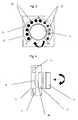
- such an arrangement for the control of blinds consists essentially of means for detecting the slat position and at least one manually operable control device 1.
- the control element 2 of the operating device 1 is assigned a switching device 3.
- the operating element 2 of the operating device 1 has a first operating option for a first operating level, and the operating element 2 of the operating device 1 has a second operating option.
- the second operating option is provided for activating the switching device 3, by the activation of which switching of the operating device 1 from the first operating level to a second operating level and from the second operating level back to the first operating level takes place.
- an electric motor N which also the Means are assigned to detect the slats positions for the slats 4 of the blind, they are adjusted by a motor in a comfortable manner.
- the operating device 1 has an operating element 2 which has two operating options.
- the first operation possibility of the operating member 2 is carried out by a parallel to the user interface of the operating device 1 to be executed rotational movement and the second operating option of the operating device 1 is carried out by a perpendicular to the user interface of the operating device 1 to be executed.
- the control element 2 is designed as a so-called rotary push knob.
- To control the slats 4 of the associated blind the control element 2 is associated with a rotary potentiometer 5, which is provided with end stops.
- the control element 2 is assigned a push-button 6 to control the switching device 3 can.
- the adjustment of the slats 4 in terms of their height or width position is made in the first operating level in the first operating level by simple rotation of the operating member 2 and the associated rotary potentiometer 5. Two end stops thereby limit the possible adjustment path of the operating member 2 and the rotary potentiometer 5.
- the desired target position of the slats 4 is preselected by the operating member 2 is rotated accordingly. This means, as can be seen in particular from FIG. B. if the slats 4 should reach 50% of their adjustment, that the control element 2 and thus the rotary potentiometer 5 is brought into its center position. In a, having a memory position setting device 7, the target position to be set is stored.
- the display of the slat positions is made directly through a mounted on the control panel 2 pointer 8 and a control panel 2 associated display panel 9 identified.
- the display panel 9 is, as is apparent in particular from Figure 1, designed as a control panel 2 surrounding display scale.
- the control element 2 may alternatively be associated with a display panel which has a plurality of LEDs or is designed as an LCD display.
- the target position for the height or Wide positions can also preselect the angular positions of the slats 4 via one and the same control element 2, and that without having to wait for the end of the travel of the slats 4 in terms of height or width adjustment.
- This is done by the user depresses the control element 2 once and thus actuates the switching device 3 via the push-button 6.
- the switching device 3 the operating device 1 is switched from its first operating level to its second operating level, ie that now by a rotation of the operating member 2, the slats 4 can be preset in terms of their angular position.
- the operating element 2 of the operating device 1 is assigned a spreading device 10 in the manner of an electronic reduction gear, so that with identical adjustment paths of the operating member 2 different adjustment speeds for the slats 4 of the blind in the first operating level and realized in the second operating level. Specifically, this means that in the first operating level, a higher and in the second operating level, a slower adjustment speed is realized. In the event of a non-actuation of more than 10 seconds, the operating device 1 is automatically returned from its second operating level to its first operating level.
- the operating device 1 has an operating element 2 which has two operating options.
- the first operation possibility of the operating member 2 is carried out by a parallel to the user interface of the operating device 1 to be executed rotational movement and the second operating option of the operating device 1 is carried out by a perpendicular to the user interface of the operating device 1 to be executed.
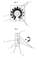
- the control element 2 is designed as a so-called rotary push knob. To control the slats 4 of the associated blind the control element 2 is assigned an incremental rotary potentiometer 11 without end stops. In addition, the control element 2 is assigned a push-button 6 to control the switching device 3 can.
- the adjustment of the slats 4 in terms of their height or width position is made in the first operating level in the first operating level by simple rotation of the operating member 2 and the associated incremental Drehpotentiometers 11. End stops are not provided, so that an endless adjustment of the operating member 2 is possible.
- the display of the slat positions is indicated directly via a control panel 2 associated with the display panel 9.
- the display panel 9 has to, as is apparent in particular from Figure 3, twelve the control element 2 surrounding LEDs 12.
- the desired target position of the slats 4 is pre-selected by the operating member 2 is rotated accordingly. This means, as can be seen in particular from FIG. B.
- the switching device 3 the operating device 1 is switched from its first operating level to its second operating level, ie that now by a rotation of the operating member 2, the slats 4 can be preset in terms of their angular position.
- the switching of the operating level can be achieved by changing the color of the LEDs 12 z. B. from red to green.
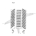
- For a rotation of the operating element 2 until the third last of the twelve LEDs 12 of the display panel 9 lights up stronger means z. B. that the lamellae 4 are tilted after reaching the target position for height or width automatically by 75% inward, as can be seen in particular from Figure 9.
- the operating element 2 of the operating device 1 is a spreading device 10 assigned in the manner of an electronic reduction gear, so that are realized at identical adjustment paths of the operating member 2 different adjustment speeds for the slats 4 of the blind in the first operating level and in the second operating level.
- the operating device 1 in the first operating level, a higher and in the second operating level, a slower adjustment speed is realized.
- the operating device 1 is automatically returned from its second operating level to its first operating level.
- the twelve LEDs 12 in the first operating level shine green and red in the second operating level.
- the twelve LEDs 12 light up depending on the set slat position in corresponding numbers in green or red. This ensures that the set slat position is clearly visible to the user.
- the operating device 1 has an operating element 2 which has two operating options.
- the first operation possibility of the operating member 2 is carried out by a parallel to the user interface of the operating device 1 to be executed rotational movement and the second operating option of the operating device 1 is carried out by a perpendicular to the user interface of the operating device 1 to be executed.
- the operating member 2 consists of a so-called finger guide groove and a centrally located recess.
- the control element 2 is a capacitive sensor arrangement 13, which also includes the push-button function associated with.
- the push-button function is assigned to the centrally arranged recess of the operating element 2 in order to be able to control the change-over device 3.
- the adjustment of the slats 4 in terms of their height or width position is made in the first operating level in the first operating level by simply circular sweeping the Finger Installationsrinne of the operating member 2 and the associated influence on the capacitive sensor assembly 13. End stops are not provided, so that an endless adjustment is possible.
- the display of the slat positions is directly on a the control element. 2 assigned display field 9 indicated.
- the display panel 9 has to, as is apparent in particular from Figure 5, twelve the operating element 2 surrounding LEDs 12.
- the desired target position of the slats 4 is preselected by the finger guide groove of the operating member 2 is swept in a circle with the finger accordingly. This means, as can be seen in particular from FIG. 8, that z. B. if the slats 4 should achieve 50% of their adjustment that the finger guide groove of the control element 2 and thus the capacitive sensor array 13 is swept over until the upper LED 12 of the display panel 9 lights up more.
- the target position to be set is stored.
- the switching device 3 By means of the switching device 3, the operating device 1 is switched from its first operating level to its second operating level, ie that the blades 4 can now be preset in terms of their angular position by sweeping the finger guide groove of the operating element 2 in a circular manner.
- the operating element 2 of the operating device 1 is assigned a spreading device 10 in the manner of an electronic reduction gear, so that with identical sweeping of the finger guide groove of the operating member 2 different adjustment speeds for the slats 4 of the blind in the first Operating level and realized in the second operating level. Specifically, this means that in the first operating level, a higher and in the second operating level, a slower adjustment speed is realized.
- the operating device 1 In the event of a non-actuation of more than 10 seconds, the operating device 1 is automatically returned from its second operating level to its first operating level. In order that the user can clearly distinguish in which operating level the operating device 1 is located, the twelve LEDs 12 in the first operating level shine green and red in the second operating level. Starting from a weak background lighting (for the first operating level in green and for the second operating level in red), the twelve LEDs 12 light up depending on the set slat position in corresponding numbers in green or red. This ensures that the set slat position is clearly visible to the user.
- such an embodiment of the operating member can also be simulated by means of a touch LCD, in which case the corresponding functions are triggered by the touch of the touch LCD, and wherein the display is realized by segments touch LCD.
Landscapes
- Engineering & Computer Science (AREA)
- Structural Engineering (AREA)
- Architecture (AREA)
- Civil Engineering (AREA)
- Blinds (AREA)
Applications Claiming Priority (1)
| Application Number | Priority Date | Filing Date | Title |
|---|---|---|---|
| DE200610041711 DE102006041711B3 (de) | 2006-09-06 | 2006-09-06 | Anordnung zur Steuerung von Jalousien |
Publications (3)
| Publication Number | Publication Date |
|---|---|
| EP1898040A2 true EP1898040A2 (fr) | 2008-03-12 |
| EP1898040A3 EP1898040A3 (fr) | 2012-11-28 |
| EP1898040B1 EP1898040B1 (fr) | 2013-10-30 |
Family
ID=38622530
Family Applications (1)
| Application Number | Title | Priority Date | Filing Date |
|---|---|---|---|
| EP20070010319 Not-in-force EP1898040B1 (fr) | 2006-09-06 | 2007-05-24 | Dispositif de commande de stores |
Country Status (2)
| Country | Link |
|---|---|
| EP (1) | EP1898040B1 (fr) |
| DE (1) | DE102006041711B3 (fr) |
Cited By (2)
| Publication number | Priority date | Publication date | Assignee | Title |
|---|---|---|---|---|
| EP2369121A2 (fr) | 2010-03-25 | 2011-09-28 | ABATEC Electronic AG | Dispositif d'input pour la commande d'un équipement domotique |
| EP3205810B1 (fr) | 2016-02-12 | 2019-11-27 | Bubendorff Sa | Appareil de commande à distance de dispositifs d'obturation de baie de type volet roulant ou battant |
Family Cites Families (4)
| Publication number | Priority date | Publication date | Assignee | Title |
|---|---|---|---|---|
| DE4404682A1 (de) * | 1994-02-15 | 1995-08-17 | Bosch Gmbh Robert | Vorrichtung zur elektronischen Steuerung der Bewegungen einer Verdunkelungsvorrichtung |
| DE29623711U1 (de) * | 1996-04-19 | 1999-05-12 | Abb Patent Gmbh, 68309 Mannheim | Einrichtung zur Steuerung einer Verdunkelungsanlage |
| DE19919200A1 (de) * | 1999-04-28 | 2000-11-02 | Becker Antriebe Gmbh | Verfahren zur Endlagenbestimmung von Toren sowie Torantrieb zur Durchführung des Verfahrens |
| DE29923046U1 (de) * | 1999-12-31 | 2000-03-23 | Rademacher, Wilhelm, 46414 Rhede | Sensor für eine Verdunkelungsvorrichtung und Verdunkelungsanlage |
-
2006
- 2006-09-06 DE DE200610041711 patent/DE102006041711B3/de not_active Expired - Fee Related
-
2007
- 2007-05-24 EP EP20070010319 patent/EP1898040B1/fr not_active Not-in-force
Cited By (3)
| Publication number | Priority date | Publication date | Assignee | Title |
|---|---|---|---|---|
| EP2369121A2 (fr) | 2010-03-25 | 2011-09-28 | ABATEC Electronic AG | Dispositif d'input pour la commande d'un équipement domotique |
| EP3205810B1 (fr) | 2016-02-12 | 2019-11-27 | Bubendorff Sa | Appareil de commande à distance de dispositifs d'obturation de baie de type volet roulant ou battant |
| EP3205810B2 (fr) † | 2016-02-12 | 2023-11-08 | Bhg | Appareil de commande à distance de dispositifs d'obturation de baie de type volet roulant ou battant |
Also Published As
| Publication number | Publication date |
|---|---|
| EP1898040A3 (fr) | 2012-11-28 |
| DE102006041711B3 (de) | 2007-11-29 |
| EP1898040B1 (fr) | 2013-10-30 |
Similar Documents
| Publication | Publication Date | Title |
|---|---|---|
| DE102010024776B4 (de) | Vorrichtung zur Bedienung mehrerer Funktionen in einem Kraftfahrzeug | |
| DE10201196A1 (de) | Stufenlos einstellbarer Regler mit Schalterfunktion für elektrotechnische Einrichtungen | |
| EP2398951A1 (fr) | Dispositif de commande pour un appareil électroménager et procédé de commande | |
| EP1075979B1 (fr) | Procédé pour la mise en oeuvre d'un dispositif de commande multifonctions d'automobile et dispositif de commande multifonctions | |
| EP1930923B1 (fr) | Dispositif de commutation pour appareils médicaux ou chirurgicaux | |
| EP2302799A2 (fr) | Procédé et dispositif destinés à la commande d'un appareil électrique | |
| EP2476859B1 (fr) | Dispositif de couverture | |
| EP1898040B1 (fr) | Dispositif de commande de stores | |
| EP3848693B1 (fr) | Microtome et procédé de commande d'un microtome à une main | |
| EP0667440A1 (fr) | Dispositif pour la commande électronique d'un dispositif d'assombrissement | |
| DE10255839B4 (de) | Bedienelement mit integrierter Anzeige | |
| WO2012146603A1 (fr) | Élément de commande pour installation d'éclairage | |
| AT14718U1 (de) | Elektrisch verstellbares Möbelstück | |
| DE102010048601B4 (de) | Eingabevorrichtung mit variablem Betätigungsgefühl | |
| DE10112973A1 (de) | Fahrzeugrechner-Bedienvorrichtung und Fahrzeugrechner-System | |
| DE19750210C2 (de) | Endschaltervorrichtung | |
| DE19752054A1 (de) | Multifunktionales Bedienteil | |
| DE19926521A1 (de) | Bedienanordnung zur elektrischen Betätigung eines motorisch betätigbaren Schiebedaches bei Kraftfahrzeugen | |
| EP3910247B1 (fr) | Hotte aspirante pourvu de module de commande | |
| DE102014009403A1 (de) | Fahrzeugsitz mit einer Rückenlehne mit einer integrierten Massageeinrichtung | |
| DE10359561A1 (de) | Bedienelement für ein Haushaltsgerät | |
| EP2637284A2 (fr) | Module de commande électrique | |
| DE102010004639A1 (de) | Steuervorrichtung zur Positionierung einer Jalousie bzw. eines Rollladens | |
| DE202007006774U1 (de) | Elektromotorischer Möbelantrieb zum Verstellen von Teilen eines Möbels relativ zueinander | |
| DE20318668U1 (de) | Mobile Trennwand, insbesondere zur Verwendung als Sichtschutzwand |
Legal Events
| Date | Code | Title | Description |
|---|---|---|---|
| PUAI | Public reference made under article 153(3) epc to a published international application that has entered the european phase |
Free format text: ORIGINAL CODE: 0009012 |
|
| AK | Designated contracting states |
Kind code of ref document: A2 Designated state(s): AT BE BG CH CY CZ DE DK EE ES FI FR GB GR HU IE IS IT LI LT LU LV MC MT NL PL PT RO SE SI SK TR |
|
| AX | Request for extension of the european patent |
Extension state: AL BA HR MK YU |
|
| RAP1 | Party data changed (applicant data changed or rights of an application transferred) |
Owner name: INSTA ELEKTRO GMBH |
|
| RAP1 | Party data changed (applicant data changed or rights of an application transferred) |
Owner name: INSTA ELEKTRO GMBH |
|
| PUAL | Search report despatched |
Free format text: ORIGINAL CODE: 0009013 |
|
| AK | Designated contracting states |
Kind code of ref document: A3 Designated state(s): AT BE BG CH CY CZ DE DK EE ES FI FR GB GR HU IE IS IT LI LT LU LV MC MT NL PL PT RO SE SI SK TR |
|
| AX | Request for extension of the european patent |
Extension state: AL BA HR MK RS |
|
| RIC1 | Information provided on ipc code assigned before grant |
Ipc: E06B 9/32 20060101AFI20121022BHEP Ipc: G05D 3/10 20060101ALI20121022BHEP |
|
| 17P | Request for examination filed |
Effective date: 20121210 |
|
| AKX | Designation fees paid |
Designated state(s): AT BE BG CH CY CZ DE DK EE ES FI FR GB GR HU IE IS IT LI LT LU LV MC MT NL PL PT RO SE SI SK TR |
|
| GRAP | Despatch of communication of intention to grant a patent |
Free format text: ORIGINAL CODE: EPIDOSNIGR1 |
|
| GRAS | Grant fee paid |
Free format text: ORIGINAL CODE: EPIDOSNIGR3 |
|
| RIC1 | Information provided on ipc code assigned before grant |
Ipc: E06B 9/32 20060101AFI20130807BHEP Ipc: G05D 3/10 20060101ALI20130807BHEP |
|
| INTG | Intention to grant announced |
Effective date: 20130828 |
|
| GRAA | (expected) grant |
Free format text: ORIGINAL CODE: 0009210 |
|
| AK | Designated contracting states |
Kind code of ref document: B1 Designated state(s): AT BE BG CH CY CZ DE DK EE ES FI FR GB GR HU IE IS IT LI LT LU LV MC MT NL PL PT RO SE SI SK TR |
|
| REG | Reference to a national code |
Ref country code: GB Ref legal event code: FG4D Free format text: NOT ENGLISH |
|
| REG | Reference to a national code |
Ref country code: CH Ref legal event code: EP |
|
| REG | Reference to a national code |
Ref country code: AT Ref legal event code: REF Ref document number: 638547 Country of ref document: AT Kind code of ref document: T Effective date: 20131115 |
|
| REG | Reference to a national code |
Ref country code: IE Ref legal event code: FG4D Free format text: LANGUAGE OF EP DOCUMENT: GERMAN |
|
| REG | Reference to a national code |
Ref country code: NL Ref legal event code: T3 |
|
| REG | Reference to a national code |
Ref country code: DE Ref legal event code: R096 Ref document number: 502007012431 Country of ref document: DE Effective date: 20131224 |
|
| REG | Reference to a national code |
Ref country code: SE Ref legal event code: TRGR |
|
| REG | Reference to a national code |
Ref country code: LT Ref legal event code: MG4D |
|
| PG25 | Lapsed in a contracting state [announced via postgrant information from national office to epo] |
Ref country code: FI Free format text: LAPSE BECAUSE OF FAILURE TO SUBMIT A TRANSLATION OF THE DESCRIPTION OR TO PAY THE FEE WITHIN THE PRESCRIBED TIME-LIMIT Effective date: 20131030 Ref country code: IS Free format text: LAPSE BECAUSE OF FAILURE TO SUBMIT A TRANSLATION OF THE DESCRIPTION OR TO PAY THE FEE WITHIN THE PRESCRIBED TIME-LIMIT Effective date: 20140228 Ref country code: LT Free format text: LAPSE BECAUSE OF FAILURE TO SUBMIT A TRANSLATION OF THE DESCRIPTION OR TO PAY THE FEE WITHIN THE PRESCRIBED TIME-LIMIT Effective date: 20131030 |
|
| PG25 | Lapsed in a contracting state [announced via postgrant information from national office to epo] |
Ref country code: ES Free format text: LAPSE BECAUSE OF FAILURE TO SUBMIT A TRANSLATION OF THE DESCRIPTION OR TO PAY THE FEE WITHIN THE PRESCRIBED TIME-LIMIT Effective date: 20131030 Ref country code: LV Free format text: LAPSE BECAUSE OF FAILURE TO SUBMIT A TRANSLATION OF THE DESCRIPTION OR TO PAY THE FEE WITHIN THE PRESCRIBED TIME-LIMIT Effective date: 20131030 Ref country code: CY Free format text: LAPSE BECAUSE OF FAILURE TO SUBMIT A TRANSLATION OF THE DESCRIPTION OR TO PAY THE FEE WITHIN THE PRESCRIBED TIME-LIMIT Effective date: 20131030 |
|
| PG25 | Lapsed in a contracting state [announced via postgrant information from national office to epo] |
Ref country code: PT Free format text: LAPSE BECAUSE OF FAILURE TO SUBMIT A TRANSLATION OF THE DESCRIPTION OR TO PAY THE FEE WITHIN THE PRESCRIBED TIME-LIMIT Effective date: 20140228 |
|
| PG25 | Lapsed in a contracting state [announced via postgrant information from national office to epo] |
Ref country code: EE Free format text: LAPSE BECAUSE OF FAILURE TO SUBMIT A TRANSLATION OF THE DESCRIPTION OR TO PAY THE FEE WITHIN THE PRESCRIBED TIME-LIMIT Effective date: 20131030 |
|
| REG | Reference to a national code |
Ref country code: DE Ref legal event code: R097 Ref document number: 502007012431 Country of ref document: DE |
|
| PG25 | Lapsed in a contracting state [announced via postgrant information from national office to epo] |
Ref country code: RO Free format text: LAPSE BECAUSE OF FAILURE TO SUBMIT A TRANSLATION OF THE DESCRIPTION OR TO PAY THE FEE WITHIN THE PRESCRIBED TIME-LIMIT Effective date: 20131030 Ref country code: CZ Free format text: LAPSE BECAUSE OF FAILURE TO SUBMIT A TRANSLATION OF THE DESCRIPTION OR TO PAY THE FEE WITHIN THE PRESCRIBED TIME-LIMIT Effective date: 20131030 Ref country code: SK Free format text: LAPSE BECAUSE OF FAILURE TO SUBMIT A TRANSLATION OF THE DESCRIPTION OR TO PAY THE FEE WITHIN THE PRESCRIBED TIME-LIMIT Effective date: 20131030 Ref country code: PL Free format text: LAPSE BECAUSE OF FAILURE TO SUBMIT A TRANSLATION OF THE DESCRIPTION OR TO PAY THE FEE WITHIN THE PRESCRIBED TIME-LIMIT Effective date: 20131030 Ref country code: IT Free format text: LAPSE BECAUSE OF FAILURE TO SUBMIT A TRANSLATION OF THE DESCRIPTION OR TO PAY THE FEE WITHIN THE PRESCRIBED TIME-LIMIT Effective date: 20131030 |
|
| PLBE | No opposition filed within time limit |
Free format text: ORIGINAL CODE: 0009261 |
|
| STAA | Information on the status of an ep patent application or granted ep patent |
Free format text: STATUS: NO OPPOSITION FILED WITHIN TIME LIMIT |
|
| PG25 | Lapsed in a contracting state [announced via postgrant information from national office to epo] |
Ref country code: DK Free format text: LAPSE BECAUSE OF FAILURE TO SUBMIT A TRANSLATION OF THE DESCRIPTION OR TO PAY THE FEE WITHIN THE PRESCRIBED TIME-LIMIT Effective date: 20131030 |
|
| 26N | No opposition filed |
Effective date: 20140731 |
|
| REG | Reference to a national code |
Ref country code: DE Ref legal event code: R097 Ref document number: 502007012431 Country of ref document: DE Effective date: 20140731 |
|
| PG25 | Lapsed in a contracting state [announced via postgrant information from national office to epo] |
Ref country code: LU Free format text: LAPSE BECAUSE OF FAILURE TO SUBMIT A TRANSLATION OF THE DESCRIPTION OR TO PAY THE FEE WITHIN THE PRESCRIBED TIME-LIMIT Effective date: 20140524 |
|
| REG | Reference to a national code |
Ref country code: CH Ref legal event code: PL |
|
| GBPC | Gb: european patent ceased through non-payment of renewal fee |
Effective date: 20140524 |
|
| PG25 | Lapsed in a contracting state [announced via postgrant information from national office to epo] |
Ref country code: CH Free format text: LAPSE BECAUSE OF NON-PAYMENT OF DUE FEES Effective date: 20140531 Ref country code: LI Free format text: LAPSE BECAUSE OF NON-PAYMENT OF DUE FEES Effective date: 20140531 Ref country code: MC Free format text: LAPSE BECAUSE OF FAILURE TO SUBMIT A TRANSLATION OF THE DESCRIPTION OR TO PAY THE FEE WITHIN THE PRESCRIBED TIME-LIMIT Effective date: 20131030 |
|
| REG | Reference to a national code |
Ref country code: IE Ref legal event code: MM4A |
|
| PG25 | Lapsed in a contracting state [announced via postgrant information from national office to epo] |
Ref country code: SI Free format text: LAPSE BECAUSE OF FAILURE TO SUBMIT A TRANSLATION OF THE DESCRIPTION OR TO PAY THE FEE WITHIN THE PRESCRIBED TIME-LIMIT Effective date: 20131030 |
|
| REG | Reference to a national code |
Ref country code: FR Ref legal event code: ST Effective date: 20150130 |
|
| PG25 | Lapsed in a contracting state [announced via postgrant information from national office to epo] |
Ref country code: IE Free format text: LAPSE BECAUSE OF NON-PAYMENT OF DUE FEES Effective date: 20140524 |
|
| PG25 | Lapsed in a contracting state [announced via postgrant information from national office to epo] |
Ref country code: GB Free format text: LAPSE BECAUSE OF NON-PAYMENT OF DUE FEES Effective date: 20140524 Ref country code: FR Free format text: LAPSE BECAUSE OF NON-PAYMENT OF DUE FEES Effective date: 20140602 |
|
| REG | Reference to a national code |
Ref country code: AT Ref legal event code: MM01 Ref document number: 638547 Country of ref document: AT Kind code of ref document: T Effective date: 20140524 |
|
| PG25 | Lapsed in a contracting state [announced via postgrant information from national office to epo] |
Ref country code: AT Free format text: LAPSE BECAUSE OF NON-PAYMENT OF DUE FEES Effective date: 20140524 |
|
| PG25 | Lapsed in a contracting state [announced via postgrant information from national office to epo] |
Ref country code: MT Free format text: LAPSE BECAUSE OF FAILURE TO SUBMIT A TRANSLATION OF THE DESCRIPTION OR TO PAY THE FEE WITHIN THE PRESCRIBED TIME-LIMIT Effective date: 20131030 |
|
| PG25 | Lapsed in a contracting state [announced via postgrant information from national office to epo] |
Ref country code: BG Free format text: LAPSE BECAUSE OF FAILURE TO SUBMIT A TRANSLATION OF THE DESCRIPTION OR TO PAY THE FEE WITHIN THE PRESCRIBED TIME-LIMIT Effective date: 20131030 |
|
| PG25 | Lapsed in a contracting state [announced via postgrant information from national office to epo] |
Ref country code: GR Free format text: LAPSE BECAUSE OF FAILURE TO SUBMIT A TRANSLATION OF THE DESCRIPTION OR TO PAY THE FEE WITHIN THE PRESCRIBED TIME-LIMIT Effective date: 20140131 |
|
| PG25 | Lapsed in a contracting state [announced via postgrant information from national office to epo] |
Ref country code: TR Free format text: LAPSE BECAUSE OF FAILURE TO SUBMIT A TRANSLATION OF THE DESCRIPTION OR TO PAY THE FEE WITHIN THE PRESCRIBED TIME-LIMIT Effective date: 20131030 Ref country code: BE Free format text: LAPSE BECAUSE OF FAILURE TO SUBMIT A TRANSLATION OF THE DESCRIPTION OR TO PAY THE FEE WITHIN THE PRESCRIBED TIME-LIMIT Effective date: 20140531 Ref country code: HU Free format text: LAPSE BECAUSE OF FAILURE TO SUBMIT A TRANSLATION OF THE DESCRIPTION OR TO PAY THE FEE WITHIN THE PRESCRIBED TIME-LIMIT; INVALID AB INITIO Effective date: 20070524 |
|
| PGFP | Annual fee paid to national office [announced via postgrant information from national office to epo] |
Ref country code: SE Payment date: 20160510 Year of fee payment: 10 Ref country code: NL Payment date: 20160530 Year of fee payment: 10 |
|
| REG | Reference to a national code |
Ref country code: DE Ref legal event code: R081 Ref document number: 502007012431 Country of ref document: DE Owner name: INSTA GMBH, DE Free format text: FORMER OWNER: INSTA ELEKTRO GMBH, 58509 LUEDENSCHEID, DE |
|
| REG | Reference to a national code |
Ref country code: SE Ref legal event code: EUG |
|
| REG | Reference to a national code |
Ref country code: NL Ref legal event code: MM Effective date: 20170601 |
|
| REG | Reference to a national code |
Ref country code: DE Ref legal event code: R084 Ref document number: 502007012431 Country of ref document: DE |
|
| PG25 | Lapsed in a contracting state [announced via postgrant information from national office to epo] |
Ref country code: SE Free format text: LAPSE BECAUSE OF NON-PAYMENT OF DUE FEES Effective date: 20170525 |
|
| PG25 | Lapsed in a contracting state [announced via postgrant information from national office to epo] |
Ref country code: NL Free format text: LAPSE BECAUSE OF NON-PAYMENT OF DUE FEES Effective date: 20170601 |
|
| PGFP | Annual fee paid to national office [announced via postgrant information from national office to epo] |
Ref country code: DE Payment date: 20210212 Year of fee payment: 15 |
|
| REG | Reference to a national code |
Ref country code: DE Ref legal event code: R119 Ref document number: 502007012431 Country of ref document: DE |
|
| PG25 | Lapsed in a contracting state [announced via postgrant information from national office to epo] |
Ref country code: DE Free format text: LAPSE BECAUSE OF NON-PAYMENT OF DUE FEES Effective date: 20221201 |