EP1898054B1 - Turbine a gaz - Google Patents
Turbine a gaz Download PDFInfo
- Publication number
- EP1898054B1 EP1898054B1 EP07114082.6A EP07114082A EP1898054B1 EP 1898054 B1 EP1898054 B1 EP 1898054B1 EP 07114082 A EP07114082 A EP 07114082A EP 1898054 B1 EP1898054 B1 EP 1898054B1
- Authority
- EP
- European Patent Office
- Prior art keywords
- sealing
- stator
- fin
- rotor
- fins
- Prior art date
- Legal status (The legal status is an assumption and is not a legal conclusion. Google has not performed a legal analysis and makes no representation as to the accuracy of the status listed.)
- Active
Links
Images

Classifications
-
- F—MECHANICAL ENGINEERING; LIGHTING; HEATING; WEAPONS; BLASTING
- F01—MACHINES OR ENGINES IN GENERAL; ENGINE PLANTS IN GENERAL; STEAM ENGINES
- F01D—NON-POSITIVE DISPLACEMENT MACHINES OR ENGINES, e.g. STEAM TURBINES
- F01D11/00—Preventing or minimising internal leakage of working-fluid, e.g. between stages
- F01D11/02—Preventing or minimising internal leakage of working-fluid, e.g. between stages by non-contact sealings, e.g. of labyrinth type
-
- F—MECHANICAL ENGINEERING; LIGHTING; HEATING; WEAPONS; BLASTING
- F01—MACHINES OR ENGINES IN GENERAL; ENGINE PLANTS IN GENERAL; STEAM ENGINES
- F01D—NON-POSITIVE DISPLACEMENT MACHINES OR ENGINES, e.g. STEAM TURBINES
- F01D11/00—Preventing or minimising internal leakage of working-fluid, e.g. between stages
- F01D11/001—Preventing or minimising internal leakage of working-fluid, e.g. between stages for sealing space between stator blade and rotor
-
- F—MECHANICAL ENGINEERING; LIGHTING; HEATING; WEAPONS; BLASTING
- F05—INDEXING SCHEMES RELATING TO ENGINES OR PUMPS IN VARIOUS SUBCLASSES OF CLASSES F01-F04
- F05D—INDEXING SCHEME FOR ASPECTS RELATING TO NON-POSITIVE-DISPLACEMENT MACHINES OR ENGINES, GAS-TURBINES OR JET-PROPULSION PLANTS
- F05D2250/00—Geometry
- F05D2250/10—Two-dimensional
- F05D2250/18—Two-dimensional patterned
- F05D2250/182—Two-dimensional patterned crenellated, notched
-
- F—MECHANICAL ENGINEERING; LIGHTING; HEATING; WEAPONS; BLASTING
- F05—INDEXING SCHEMES RELATING TO ENGINES OR PUMPS IN VARIOUS SUBCLASSES OF CLASSES F01-F04
- F05D—INDEXING SCHEME FOR ASPECTS RELATING TO NON-POSITIVE-DISPLACEMENT MACHINES OR ENGINES, GAS-TURBINES OR JET-PROPULSION PLANTS
- F05D2250/00—Geometry
- F05D2250/20—Three-dimensional
- F05D2250/28—Three-dimensional patterned
- F05D2250/283—Three-dimensional patterned honeycomb
-
- F—MECHANICAL ENGINEERING; LIGHTING; HEATING; WEAPONS; BLASTING
- F05—INDEXING SCHEMES RELATING TO ENGINES OR PUMPS IN VARIOUS SUBCLASSES OF CLASSES F01-F04
- F05D—INDEXING SCHEME FOR ASPECTS RELATING TO NON-POSITIVE-DISPLACEMENT MACHINES OR ENGINES, GAS-TURBINES OR JET-PROPULSION PLANTS
- F05D2250/00—Geometry
- F05D2250/30—Arrangement of components
- F05D2250/31—Arrangement of components according to the direction of their main axis or their axis of rotation
- F05D2250/314—Arrangement of components according to the direction of their main axis or their axis of rotation the axes being inclined in relation to each other
Definitions
- the invention relates to a turbomachine, in particular a gas turbine, having a rotor and a stator and an axial sealing device arranged between the rotor and the stator, according to the preamble of claim 1.
- turbomachines In order to be able to produce the highest possible efficiency in modern turbomachines, in particular in gas turbines or compressors, it is desirable to effectively seal the turbomachine and thereby avoid a loss of the turbomachine driving hot gases as well as a collapse of cooling gases, the temperature within the Reduce flow machine and thereby adversely affect the efficiency.
- a particular problem with the sealing of such turbomachines occurs in particular when the sealing device is arranged between relatively moving component components. This is for example the case with a sealing device which is arranged between a rotating rotor and a stator fixed relative thereto. Additional relative movements of the opposing sealing device components occur at the transition from the thermally cold resting state to the warm operating state due to the thermal expansion and the mechanical load at different material properties of the supporting parts.
- a stator-side radially stepped sealing contour is provided in the case of such sealing devices, which has regions that project back and forth in the direction of the rotor.
- a plurality of sealing fins projecting in the direction of the stator are arranged, which respectively engage in adjacent, recessed regions of the stator-side sealing contour.
- a poor sealing property of the sealing device also results in a hot gas breakdown in the sealing region, which accelerates an oxidation process and thus also corrosion.
- the invention deals with the problem of providing an improved or at least another embodiment for a turbomachine of the generic type, which is characterized in particular by an improved sealing effect of an associated sealing device.
- the invention is based on the general idea, in a turbomachine with at least one arranged between a rotor and a stator axial sealing device in addition to the already commonly existing sealing fins so-called. Additional fins provide, which increase a labyrinth effect of the sealing device and thereby improve the sealing effect of the sealing device.
- the sealing device on the stator side has a radially stepped sealing contour with regions projecting back and forth in the direction of the rotor. In each adjacent, recessed areas of the stator-side sealing contour engage on the rotor side and projecting in the direction of the stator sealing fins, which already a certain labyrinth seal is provided in conventional sealing devices.
- At least one additional fin protruding in the direction of the stator is provided on the rotor side, which lies opposite a projecting region of the stator-side sealing contour and is positioned between two adjacent fins arranged on the rotor side.
- the additional fins can in the same way as the sealing fins be formed and, for example, consist of erosive material, while the opposite sealing contour consists oftechnologytragendem material, so that optionally the additional fins may possibly dig into a surface of the sealing contour.
- both the additional fins and the sealing fins abut against the opposite regions of the sealing contour.
- Both the additional fins and the sealing fins are formed as continuous contours in the circumferential direction of the rotor, whereby they receive the shape of a projecting collar of the rotor.
- the stator-side sealing contour is also constructed substantially uniformly in the circumferential direction so that the regions of the sealing contour projecting radially back and forth in the axial longitudinal section are annular.
- the arrangement of at least one additional fin substantially improves the labyrinth effect and thus the sealing effect of the sealing device.
- At least one additional fin and / or one sealing fin are arranged radially and axially inclined on the rotor or on a rotor-side heat shield.
- An inclination in the direction opposite to the main flow direction of the sealing fin or the additional fin amplifies a flow upstream and downstream of the respective fin located Stauströmung, or a so-called. Totwasser Scheme, which counteracts the flow and thereby improves the sealing effect of the sealing device.
- the inclined fins deform radially outward due to the centrifugal forces and thereby create the opposite sealing contour.
- a burying of the fins can take place in the honeycomb-shaped sealing structure, wherein a removal of material should take place exclusively in the region of the sealing contour.
- the sealing fins and / or the additional fin in the circumferential direction each one wedge-shaped cross-sectional profile.
- a wedge-shaped cross-sectional profile provides a wide connection base to the rotor and thereby a reliable connection of the fin with the rotor and at the same time a weight-optimized fin, as it tapers radially outward.
- This is particularly favorable for attacking centrifugal forces, since a cross-sectionally uniform fin would produce significantly greater centrifugal forces at its free end, which causes a significantly greater load on the connection region of the fin to the rotor or on a heat shield of the rotor.
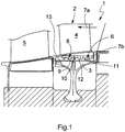
- FIG. 1 has a turbomachine 1, in particular a gas turbine or a compressor, a stator 2 and a rotor 3.
- the stator 2 may be formed, for example, as a guide blade 4.
- a blade 5 can be arranged in the usual manner.
- at least one sealing device 6 is arranged between the stator 2 and the rotor 3. The sealing device 6 extends in the axial direction of the turbomachine 1.
- the sealing device 6 has a honeycomb-shaped and radially stepped sealing contour 8 with in the direction of the rotor 3 back and forth areas 9 and 10 (see also Fig. 2 ).
- a plurality of sealing fins 11 projecting in the direction of the stator 2 are arranged, which respectively engage in adjacent, recessed regions 10 of the stator-side sealing contour 8.
- at least one additional fin 12 projecting in the direction of the stator 2 is additionally provided on the rotor side, which is positioned between two adjacent sealing fins 11 arranged on the rotor side and faces a projecting region 9 of the stator-side sealing contour 8.
- so-called additional fins 12 are additionally arranged which abut against the projecting regions 9 of the sealing contour 8 or even dig into them.
- Both the sealing fins 11 and the additional fins 12 are made of a wear-resistant compared to the sealing contour 8 material, so at a Contact between the fins 11, 12 and the sealing contour 8, a removal of the sealing contour 8 takes place and the fins 11, 12 dig into the sealing contour 8, whereby the sealing effect of the sealing device 6 is additionally improved.
- At least one additional fin 12 and / or a sealing fin 11 are arranged radially and axially inclined on the rotor 3 and on a heat shield 13 of the rotor 3.
- a degree of inclination of the at least one additional fin 12 or the at least one sealing fin 11 is approximately 25 ° -35 ° with respect to a radial perpendicular to the axis of the turbomachine 1.
- the inclination of the sealing fins 11 and the additional fins 12 takes place in opposite to the main flow 7a Direction, whereby upstream and / or downstream of the respective fin 11, 12 can form a so-called.
- the reference character 7b designates the leakage flow between the stator 2 and the rotor 3.
- the sealing means 6 according to the Fig. 2a to d have over their entire axial extent a constant radial height, while a radial height of the sealing device 6 according to the Fig. 2e changed in the axial direction of the turbomachine 1.
- These sealing devices 6 are particularly suitable for cases in which the axial relative movement is greater than the radial. For this reason, all sealing devices 6 according to the Fig.
- sealing devices 6 according to the Fig. 1 and 2 is common that at least the sealing fins 11 each have a wedge-shaped cross-sectional profile in the circumferential direction and thereby taper, starting from their rotor-side connection up to a free end.
- This offers the advantage that a connection area on the rotor side is made stronger and therefore more loadable, while the free end of the sealing fin 11 is significantly lighter and thus causes lower centrifugal forces or centrifugal forces.
- stator-side, recessed portion 10 preferably has an axial longitudinal extent of about two to three times the height h of the sealing fin 11 shown in longitudinal section, while a stator Weger, projecting portion 9 an axial longitudinal extent of about 1 to 2.5 times the Height h, that is, has a width b shown in longitudinal section of 1 to 2.5 times h.
- a radial height of the sealing fin 11 is approximately 2 to 4 times greater than a radial height of the additional fin 12.
- the radial height of both the additional fin is oriented 12 and the sealing fin 11 to constructive requirements.
- Fig. 2a to c and 2e is a last projecting portion 9 'much narrower, that is formed with a much smaller axial longitudinal extent, while according to the Fig. 2b completely missing.
- combinations of sealing fins 11 and additional fins 12 optimized with respect to the sealing effect can be used, wherein the sealing fins 1 and / or the additional fins can preferably be inclined opposite to the main flow direction 7a.
Landscapes
- Engineering & Computer Science (AREA)
- Mechanical Engineering (AREA)
- General Engineering & Computer Science (AREA)
- Turbine Rotor Nozzle Sealing (AREA)
- Structures Of Non-Positive Displacement Pumps (AREA)
Claims (5)
- Turbomachine (1), plus particulièrement turbine à gaz,- avec un stator (2) et un rotor (3) ainsi qu'un dispositif d'étanchéité axial (6) disposé entre le stator (2) et le rotor (3),- le dispositif d'étanchéité (6) comprenant, du côté du stator, un contour d'étanchéité étagé radialement (8) avec des zones en saillie et en retrait (9, 10) en direction du rotor (3),- moyennant quoi, du côté du rotor, plusieurs ailettes d'étanchéité (11) s'étendant en direction du stator (2) sont disposées, qui s'emboîtent chacune dans des zones en retrait (10) adjacentes du contour d'étanchéité côté stator (8),- moyennant quoi, du côté du rotor, est prévue au moins une ailette supplémentaire (12) s'étendant en direction du stator (2), qui est située entre deux ailettes d'étanchéité (11) adjacentes disposées du côté du rotor et qui est disposée en face d'une zone en saillie (9) du contour d'étanchéité côté stator (8),- moyennant quoi une zone en retrait côté stator (10) est plus large qu'une zone en saillie côté stator (9),- moyennant quoi la hauteur radiale (h) de l'ailette d'étanchéité (11) est environ 2 à 4 fois plus grande qu'une hauteur radiale de l'ailette supplémentaire (12), caractérisée en ce queau moins une ailette supplémentaire (12) et/ou une ailette d'étanchéité (11) est/sont disposée(s) de manière radiale et axiale par rapport au rotor (3) et
un angle d'inclinaison de l'au moins une ailette supplémentaire (12) et/ou de l'au moins une ailette d'étanchéité (11) est d'environ 25° à 35°. - Turbomachine selon la revendication 1,
caractérisée en ce que
l'au moins une ailette supplémentaire (12) et/ou l'au moins une ailette d'étanchéité (11) est/sont inclinée(s) dans une direction opposée à l'écoulement principal (7a). - Turbomachine selon l'une des revendications 1 ou 2,
caractérisée en ce que
une distance axiale entre deux zones en saillie ou en retrait côté stator (9, 10) est approximativement deux fois plus grande qu'une hauteur radiale de l'ailette d'étanchéité (11). - Turbomachine selon l'une des revendications 1 à 3,
caractérisée en ce que
une zone en retrait côté stator (10) présente une extension longitudinale axiale d'environ deux à trois fois une hauteur radiale (h) de l'ailette d'étanchéité (11), tandis qu'une zone en saillie côté stator (9) présente une extension longitudinale axiale d'environ 1 à 2,5 fois la hauteur radiale (h). - Turbomachine selon l'une des revendications 1 à 4,
caractérisée en ce que
les ailettes d'étanchéité (11) présentent chacune, dans la direction circonférentielle, un profil de section transversale cunéiforme.
Applications Claiming Priority (1)
| Application Number | Priority Date | Filing Date | Title |
|---|---|---|---|
| CH13592006 | 2006-08-25 |
Publications (2)
| Publication Number | Publication Date |
|---|---|
| EP1898054A1 EP1898054A1 (fr) | 2008-03-12 |
| EP1898054B1 true EP1898054B1 (fr) | 2018-05-30 |
Family
ID=37441281
Family Applications (1)
| Application Number | Title | Priority Date | Filing Date |
|---|---|---|---|
| EP07114082.6A Active EP1898054B1 (fr) | 2006-08-25 | 2007-08-09 | Turbine a gaz |
Country Status (2)
| Country | Link |
|---|---|
| US (1) | US8182211B2 (fr) |
| EP (1) | EP1898054B1 (fr) |
Families Citing this family (14)
| Publication number | Priority date | Publication date | Assignee | Title |
|---|---|---|---|---|
| US8376697B2 (en) * | 2008-09-25 | 2013-02-19 | Siemens Energy, Inc. | Gas turbine sealing apparatus |
| US8221062B2 (en) * | 2009-01-14 | 2012-07-17 | General Electric Company | Device and system for reducing secondary air flow in a gas turbine |
| US8561997B2 (en) * | 2010-01-05 | 2013-10-22 | General Electric Company | Adverse pressure gradient seal mechanism |
| US8845284B2 (en) | 2010-07-02 | 2014-09-30 | General Electric Company | Apparatus and system for sealing a turbine rotor |
| US8434766B2 (en) * | 2010-08-18 | 2013-05-07 | General Electric Company | Turbine engine seals |
| GB2492546A (en) * | 2011-07-04 | 2013-01-09 | Alstom Technology Ltd | A labyrinth seal for an axial fluid flow turbomachine |
| US8864453B2 (en) | 2012-01-20 | 2014-10-21 | General Electric Company | Near flow path seal for a turbomachine |
| US20130186103A1 (en) * | 2012-01-20 | 2013-07-25 | General Electric Company | Near flow path seal for a turbomachine |
| US9080456B2 (en) | 2012-01-20 | 2015-07-14 | General Electric Company | Near flow path seal with axially flexible arms |
| JP2014020509A (ja) * | 2012-07-20 | 2014-02-03 | Toshiba Corp | シール装置、軸流タービン、および発電プラント |
| US10036278B2 (en) * | 2014-04-11 | 2018-07-31 | United Technologies Corporation | High pressure compressor thermal shield apparatus and system |
| JP6601677B2 (ja) * | 2016-02-16 | 2019-11-06 | 三菱日立パワーシステムズ株式会社 | シール装置及び回転機械 |
| EP3318724A1 (fr) * | 2016-11-04 | 2018-05-09 | Siemens Aktiengesellschaft | Segment d'étanchéité d'un rotor et rotor |
| CN112671124B (zh) * | 2020-12-26 | 2023-01-13 | 山东双华易驱智能制造研究院有限公司 | 一种电机内定子和电机 |
Citations (1)
| Publication number | Priority date | Publication date | Assignee | Title |
|---|---|---|---|---|
| EP0894947A2 (fr) * | 1997-07-30 | 1999-02-03 | Mitsubishi Heavy Industries, Ltd. | Joint inter-étages pour turbines à gaz |
Family Cites Families (9)
| Publication number | Priority date | Publication date | Assignee | Title |
|---|---|---|---|---|
| DE668667C (de) * | 1938-12-08 | Oerlikon Maschf | Vorrichtung zur Verminderung der Dampfverluste bei Labyrinthdichtungen fuer umlaufende Wellen | |
| US1708044A (en) * | 1923-09-12 | 1929-04-09 | Westinghouse Electric & Mfg Co | Labyrinth-gland packing |
| US3251601A (en) * | 1963-03-20 | 1966-05-17 | Gen Motors Corp | Labyrinth seal |
| US4103899A (en) * | 1975-10-01 | 1978-08-01 | United Technologies Corporation | Rotary seal with pressurized air directed at fluid approaching the seal |
| US5029876A (en) * | 1988-12-14 | 1991-07-09 | General Electric Company | Labyrinth seal system |
| DE59609405D1 (de) | 1996-04-01 | 2002-08-08 | Alstom | Wandkontur für eine axiale Strömungsmaschine |
| US5961279A (en) * | 1996-05-31 | 1999-10-05 | Atlantic Richfield Company | Turbine power plant having minimal-contact brush seal augmented labyrinth seal |
| DE19940525A1 (de) * | 1999-08-26 | 2001-03-01 | Asea Brown Boveri | Wärmestaueinheit für eine Rotoranordnung |
| US20040239040A1 (en) | 2003-05-29 | 2004-12-02 | Burdgick Steven Sebastian | Nozzle interstage seal for steam turbines |
-
2007
- 2007-08-09 EP EP07114082.6A patent/EP1898054B1/fr active Active
- 2007-08-20 US US11/841,333 patent/US8182211B2/en not_active Expired - Fee Related
Patent Citations (1)
| Publication number | Priority date | Publication date | Assignee | Title |
|---|---|---|---|---|
| EP0894947A2 (fr) * | 1997-07-30 | 1999-02-03 | Mitsubishi Heavy Industries, Ltd. | Joint inter-étages pour turbines à gaz |
Also Published As
| Publication number | Publication date |
|---|---|
| EP1898054A1 (fr) | 2008-03-12 |
| US8182211B2 (en) | 2012-05-22 |
| US20080050233A1 (en) | 2008-02-28 |
Similar Documents
| Publication | Publication Date | Title |
|---|---|---|
| EP1898054B1 (fr) | Turbine a gaz | |
| EP1320662B1 (fr) | Systeme de garniture d'etancheite | |
| DE102011055150B4 (de) | Turbinenschaufelanordnung | |
| DE10210866C5 (de) | Leitschaufelbefestigung in einem Strömungskanal einer Fluggasturbine | |
| DE69105837T2 (de) | Gekühlte Turbinenschaufel. | |
| EP1293644A1 (fr) | Support pour aubes statoriques et segment d'accumulation de chaleur | |
| EP3051068A1 (fr) | Bague d'aube directrice pour une turbomachine et procédé de fabrication additive | |
| DE112016003244T5 (de) | Abdeckung für Axialgebläseanordnung | |
| EP2478186B1 (fr) | Rotor de turbomachine | |
| CH707459A2 (de) | Innenkühlungsaufbau einer Turbinenlaufschaufel. | |
| CH697747B1 (de) | Gasturbine. | |
| EP2092164B1 (fr) | Turbo machine, en particulier turbine à gaz | |
| DE102007050916A1 (de) | Verfahren und Vorrichtung zum Zusammenbau von Gasturbinen-Triebwerken | |
| EP3324002A1 (fr) | Système d'étanchéité pour une turbomachine axiale et turbomachine axiale | |
| EP3412875A2 (fr) | Structure de rodage pour une turbomachine et procédé de fabrication d'une structure de rodage | |
| EP2647796A1 (fr) | Système d'étanchéité pour turbomachine | |
| EP3379037B1 (fr) | Étanchéité sur une bague intérieure d'une couronne d'aubes directrices | |
| EP3287608B1 (fr) | Bague intérieure d'une couronne d'aubes directrices d'une turbomachine | |
| DE602004006035T2 (de) | Kühleinrichtung für Turbinenscheiben | |
| EP3263838A1 (fr) | Pale de turbine avec canal de refroidissement interne | |
| EP2410131A2 (fr) | Rotor d'une turbomachine | |
| EP3109520B1 (fr) | Support d'étanchéité, stator et turbomachine | |
| EP3521562B1 (fr) | Aube d'une turbomachine | |
| DE102009007664A1 (de) | Abdichtvorrichtung an dem Schaufelschaft einer Rotorstufe einer axialen Strömungsmaschine | |
| EP1653049B1 (fr) | Couronne d'aubes directrices pour turbines à gaz et procédé pour sa modification |
Legal Events
| Date | Code | Title | Description |
|---|---|---|---|
| PUAI | Public reference made under article 153(3) epc to a published international application that has entered the european phase |
Free format text: ORIGINAL CODE: 0009012 |
|
| AK | Designated contracting states |
Kind code of ref document: A1 Designated state(s): AT BE BG CH CY CZ DE DK EE ES FI FR GB GR HU IE IS IT LI LT LU LV MC MT NL PL PT RO SE SI SK TR |
|
| AX | Request for extension of the european patent |
Extension state: AL BA HR MK YU |
|
| 17P | Request for examination filed |
Effective date: 20080904 |
|
| AKX | Designation fees paid |
Designated state(s): AT BE BG CH CY CZ DE DK EE ES FI FR GB GR HU IE IS IT LI LT LU LV MC MT NL PL PT RO SE SI SK TR |
|
| 17Q | First examination report despatched |
Effective date: 20150120 |
|
| RAP1 | Party data changed (applicant data changed or rights of an application transferred) |
Owner name: GENERAL ELECTRIC TECHNOLOGY GMBH |
|
| RAP1 | Party data changed (applicant data changed or rights of an application transferred) |
Owner name: ANSALDO ENERGIA IP UK LIMITED |
|
| GRAP | Despatch of communication of intention to grant a patent |
Free format text: ORIGINAL CODE: EPIDOSNIGR1 |
|
| INTG | Intention to grant announced |
Effective date: 20171214 |
|
| GRAS | Grant fee paid |
Free format text: ORIGINAL CODE: EPIDOSNIGR3 |
|
| GRAA | (expected) grant |
Free format text: ORIGINAL CODE: 0009210 |
|
| AK | Designated contracting states |
Kind code of ref document: B1 Designated state(s): AT BE BG CH CY CZ DE DK EE ES FI FR GB GR HU IE IS IT LI LT LU LV MC MT NL PL PT RO SE SI SK TR |
|
| REG | Reference to a national code |
Ref country code: GB Ref legal event code: FG4D Free format text: NOT ENGLISH |
|
| REG | Reference to a national code |
Ref country code: CH Ref legal event code: EP |
|
| REG | Reference to a national code |
Ref country code: AT Ref legal event code: REF Ref document number: 1003800 Country of ref document: AT Kind code of ref document: T Effective date: 20180615 |
|
| REG | Reference to a national code |
Ref country code: DE Ref legal event code: R096 Ref document number: 502007016203 Country of ref document: DE |
|
| REG | Reference to a national code |
Ref country code: IE Ref legal event code: FG4D Free format text: LANGUAGE OF EP DOCUMENT: GERMAN |
|
| REG | Reference to a national code |
Ref country code: NL Ref legal event code: MP Effective date: 20180530 |
|
| REG | Reference to a national code |
Ref country code: LT Ref legal event code: MG4D |
|
| PG25 | Lapsed in a contracting state [announced via postgrant information from national office to epo] |
Ref country code: SE Free format text: LAPSE BECAUSE OF FAILURE TO SUBMIT A TRANSLATION OF THE DESCRIPTION OR TO PAY THE FEE WITHIN THE PRESCRIBED TIME-LIMIT Effective date: 20180530 Ref country code: CY Free format text: LAPSE BECAUSE OF FAILURE TO SUBMIT A TRANSLATION OF THE DESCRIPTION OR TO PAY THE FEE WITHIN THE PRESCRIBED TIME-LIMIT Effective date: 20180530 Ref country code: FI Free format text: LAPSE BECAUSE OF FAILURE TO SUBMIT A TRANSLATION OF THE DESCRIPTION OR TO PAY THE FEE WITHIN THE PRESCRIBED TIME-LIMIT Effective date: 20180530 Ref country code: BG Free format text: LAPSE BECAUSE OF FAILURE TO SUBMIT A TRANSLATION OF THE DESCRIPTION OR TO PAY THE FEE WITHIN THE PRESCRIBED TIME-LIMIT Effective date: 20180830 Ref country code: ES Free format text: LAPSE BECAUSE OF FAILURE TO SUBMIT A TRANSLATION OF THE DESCRIPTION OR TO PAY THE FEE WITHIN THE PRESCRIBED TIME-LIMIT Effective date: 20180530 Ref country code: LT Free format text: LAPSE BECAUSE OF FAILURE TO SUBMIT A TRANSLATION OF THE DESCRIPTION OR TO PAY THE FEE WITHIN THE PRESCRIBED TIME-LIMIT Effective date: 20180530 |
|
| PG25 | Lapsed in a contracting state [announced via postgrant information from national office to epo] |
Ref country code: LV Free format text: LAPSE BECAUSE OF FAILURE TO SUBMIT A TRANSLATION OF THE DESCRIPTION OR TO PAY THE FEE WITHIN THE PRESCRIBED TIME-LIMIT Effective date: 20180530 Ref country code: GR Free format text: LAPSE BECAUSE OF FAILURE TO SUBMIT A TRANSLATION OF THE DESCRIPTION OR TO PAY THE FEE WITHIN THE PRESCRIBED TIME-LIMIT Effective date: 20180831 |
|
| PG25 | Lapsed in a contracting state [announced via postgrant information from national office to epo] |
Ref country code: NL Free format text: LAPSE BECAUSE OF FAILURE TO SUBMIT A TRANSLATION OF THE DESCRIPTION OR TO PAY THE FEE WITHIN THE PRESCRIBED TIME-LIMIT Effective date: 20180530 |
|
| PG25 | Lapsed in a contracting state [announced via postgrant information from national office to epo] |
Ref country code: DK Free format text: LAPSE BECAUSE OF FAILURE TO SUBMIT A TRANSLATION OF THE DESCRIPTION OR TO PAY THE FEE WITHIN THE PRESCRIBED TIME-LIMIT Effective date: 20180530 Ref country code: CZ Free format text: LAPSE BECAUSE OF FAILURE TO SUBMIT A TRANSLATION OF THE DESCRIPTION OR TO PAY THE FEE WITHIN THE PRESCRIBED TIME-LIMIT Effective date: 20180530 Ref country code: RO Free format text: LAPSE BECAUSE OF FAILURE TO SUBMIT A TRANSLATION OF THE DESCRIPTION OR TO PAY THE FEE WITHIN THE PRESCRIBED TIME-LIMIT Effective date: 20180530 Ref country code: EE Free format text: LAPSE BECAUSE OF FAILURE TO SUBMIT A TRANSLATION OF THE DESCRIPTION OR TO PAY THE FEE WITHIN THE PRESCRIBED TIME-LIMIT Effective date: 20180530 Ref country code: PL Free format text: LAPSE BECAUSE OF FAILURE TO SUBMIT A TRANSLATION OF THE DESCRIPTION OR TO PAY THE FEE WITHIN THE PRESCRIBED TIME-LIMIT Effective date: 20180530 Ref country code: SK Free format text: LAPSE BECAUSE OF FAILURE TO SUBMIT A TRANSLATION OF THE DESCRIPTION OR TO PAY THE FEE WITHIN THE PRESCRIBED TIME-LIMIT Effective date: 20180530 |
|
| PG25 | Lapsed in a contracting state [announced via postgrant information from national office to epo] |
Ref country code: IT Free format text: LAPSE BECAUSE OF FAILURE TO SUBMIT A TRANSLATION OF THE DESCRIPTION OR TO PAY THE FEE WITHIN THE PRESCRIBED TIME-LIMIT Effective date: 20180530 |
|
| REG | Reference to a national code |
Ref country code: DE Ref legal event code: R097 Ref document number: 502007016203 Country of ref document: DE |
|
| PG25 | Lapsed in a contracting state [announced via postgrant information from national office to epo] |
Ref country code: MC Free format text: LAPSE BECAUSE OF FAILURE TO SUBMIT A TRANSLATION OF THE DESCRIPTION OR TO PAY THE FEE WITHIN THE PRESCRIBED TIME-LIMIT Effective date: 20180530 |
|
| REG | Reference to a national code |
Ref country code: CH Ref legal event code: PL |
|
| PLBE | No opposition filed within time limit |
Free format text: ORIGINAL CODE: 0009261 |
|
| STAA | Information on the status of an ep patent application or granted ep patent |
Free format text: STATUS: NO OPPOSITION FILED WITHIN TIME LIMIT |
|
| PG25 | Lapsed in a contracting state [announced via postgrant information from national office to epo] |
Ref country code: CH Free format text: LAPSE BECAUSE OF NON-PAYMENT OF DUE FEES Effective date: 20180831 Ref country code: LU Free format text: LAPSE BECAUSE OF NON-PAYMENT OF DUE FEES Effective date: 20180809 Ref country code: LI Free format text: LAPSE BECAUSE OF NON-PAYMENT OF DUE FEES Effective date: 20180831 |
|
| 26N | No opposition filed |
Effective date: 20190301 |
|
| REG | Reference to a national code |
Ref country code: BE Ref legal event code: MM Effective date: 20180831 |
|
| REG | Reference to a national code |
Ref country code: IE Ref legal event code: MM4A |
|
| PG25 | Lapsed in a contracting state [announced via postgrant information from national office to epo] |
Ref country code: SI Free format text: LAPSE BECAUSE OF FAILURE TO SUBMIT A TRANSLATION OF THE DESCRIPTION OR TO PAY THE FEE WITHIN THE PRESCRIBED TIME-LIMIT Effective date: 20180530 |
|
| PG25 | Lapsed in a contracting state [announced via postgrant information from national office to epo] |
Ref country code: IE Free format text: LAPSE BECAUSE OF NON-PAYMENT OF DUE FEES Effective date: 20180809 |
|
| PG25 | Lapsed in a contracting state [announced via postgrant information from national office to epo] |
Ref country code: BE Free format text: LAPSE BECAUSE OF NON-PAYMENT OF DUE FEES Effective date: 20180831 Ref country code: FR Free format text: LAPSE BECAUSE OF NON-PAYMENT OF DUE FEES Effective date: 20180831 |
|
| REG | Reference to a national code |
Ref country code: AT Ref legal event code: MM01 Ref document number: 1003800 Country of ref document: AT Kind code of ref document: T Effective date: 20180809 |
|
| PG25 | Lapsed in a contracting state [announced via postgrant information from national office to epo] |
Ref country code: AT Free format text: LAPSE BECAUSE OF NON-PAYMENT OF DUE FEES Effective date: 20180809 |
|
| PG25 | Lapsed in a contracting state [announced via postgrant information from national office to epo] |
Ref country code: MT Free format text: LAPSE BECAUSE OF FAILURE TO SUBMIT A TRANSLATION OF THE DESCRIPTION OR TO PAY THE FEE WITHIN THE PRESCRIBED TIME-LIMIT Effective date: 20180530 |
|
| PG25 | Lapsed in a contracting state [announced via postgrant information from national office to epo] |
Ref country code: TR Free format text: LAPSE BECAUSE OF FAILURE TO SUBMIT A TRANSLATION OF THE DESCRIPTION OR TO PAY THE FEE WITHIN THE PRESCRIBED TIME-LIMIT Effective date: 20180530 |
|
| PG25 | Lapsed in a contracting state [announced via postgrant information from national office to epo] |
Ref country code: HU Free format text: LAPSE BECAUSE OF FAILURE TO SUBMIT A TRANSLATION OF THE DESCRIPTION OR TO PAY THE FEE WITHIN THE PRESCRIBED TIME-LIMIT; INVALID AB INITIO Effective date: 20070809 Ref country code: PT Free format text: LAPSE BECAUSE OF FAILURE TO SUBMIT A TRANSLATION OF THE DESCRIPTION OR TO PAY THE FEE WITHIN THE PRESCRIBED TIME-LIMIT Effective date: 20180530 |
|
| PG25 | Lapsed in a contracting state [announced via postgrant information from national office to epo] |
Ref country code: IS Free format text: LAPSE BECAUSE OF FAILURE TO SUBMIT A TRANSLATION OF THE DESCRIPTION OR TO PAY THE FEE WITHIN THE PRESCRIBED TIME-LIMIT Effective date: 20180930 |
|
| P01 | Opt-out of the competence of the unified patent court (upc) registered |
Effective date: 20240430 |
|
| PGFP | Annual fee paid to national office [announced via postgrant information from national office to epo] |
Ref country code: DE Payment date: 20240819 Year of fee payment: 18 |
|
| PGFP | Annual fee paid to national office [announced via postgrant information from national office to epo] |
Ref country code: GB Payment date: 20240822 Year of fee payment: 18 |
|
| REG | Reference to a national code |
Ref country code: DE Ref legal event code: R119 Ref document number: 502007016203 Country of ref document: DE |