EP2410131A2 - Rotor d'une turbomachine - Google Patents
Rotor d'une turbomachine Download PDFInfo
- Publication number
- EP2410131A2 EP2410131A2 EP11161987A EP11161987A EP2410131A2 EP 2410131 A2 EP2410131 A2 EP 2410131A2 EP 11161987 A EP11161987 A EP 11161987A EP 11161987 A EP11161987 A EP 11161987A EP 2410131 A2 EP2410131 A2 EP 2410131A2
- Authority
- EP
- European Patent Office
- Prior art keywords
- blade
- rotor
- coupling element
- radially
- blades
- Prior art date
- Legal status (The legal status is an assumption and is not a legal conclusion. Google has not performed a legal analysis and makes no representation as to the accuracy of the status listed.)
- Granted
Links
Images


Classifications
-
- F—MECHANICAL ENGINEERING; LIGHTING; HEATING; WEAPONS; BLASTING
- F01—MACHINES OR ENGINES IN GENERAL; ENGINE PLANTS IN GENERAL; STEAM ENGINES
- F01D—NON-POSITIVE DISPLACEMENT MACHINES OR ENGINES, e.g. STEAM TURBINES
- F01D5/00—Blades; Blade-carrying members; Heating, heat-insulating, cooling or antivibration means on the blades or the members
- F01D5/12—Blades
- F01D5/22—Blade-to-blade connections, e.g. for damping vibrations
- F01D5/225—Blade-to-blade connections, e.g. for damping vibrations by shrouding
-
- F—MECHANICAL ENGINEERING; LIGHTING; HEATING; WEAPONS; BLASTING
- F05—INDEXING SCHEMES RELATING TO ENGINES OR PUMPS IN VARIOUS SUBCLASSES OF CLASSES F01-F04
- F05D—INDEXING SCHEME FOR ASPECTS RELATING TO NON-POSITIVE-DISPLACEMENT MACHINES OR ENGINES, GAS-TURBINES OR JET-PROPULSION PLANTS
- F05D2250/00—Geometry
- F05D2250/70—Shape
- F05D2250/73—Shape asymmetric
Definitions
- the invention relates to a rotor of a turbomachine according to the preamble of claim 1.
- a rotor of a turbomachine in particular a gas turbine or steam turbine, has a rotor base body and a plurality of rotor blades which are fastened to the rotor base body.
- the blades of such a turbomachinery rotor have a blade root and an airfoil, each blade being secured via its blade root to the rotor body in a groove of the rotor body in a mounting direction defined by the blade roots, and each blade having at least one coupler segment in the region of its airfoil when it is positioned radially outward on the airfoil, is formed as an outer shroud segment.
- the coupling element segments, in particular outer shroud segments, of all the moving blades of such a turbomachine rotor together form at least one coupling element closed in the circumferential direction, in particular an outer shroud, of the rotor.
- a width of a coupling element segment, in particular an outer shroud segment, of each blade is defined by edges extending substantially in the axial direction.
- a depth in the axial direction of the coupling element segment, in particular the outer shroud segment, of each blade is defined by substantially circumferentially extending edges.
- a coupling element segment, in particular an outer shroud segment, each blade is also characterized by a thickness in the radial direction.
- Turbomachine rotors whose rotor blades have such coupling element segments for forming at least one coupling element can be installed both in the region of a compressor and in the region of a turbine of the turbomachine.
- Turbomachinery rotors on the rotor base body of which rotor blades are fastened, which have a coupling element segment formed radially on the outside of the airfoil as an outer cover band segment, are for example made DE 1 159 965 C , out DE 40 15 206 C1 as well as out US 4,400,915 A and from GB 2 072 760 A known. From the EP 1 134 359 A1 and the DE 1 122 551 C the attachment of the blades on the blade roots on the rotor base body in a groove of the rotor base body in a mounting direction defined by the blade feet is known. The blade feet may be fir-tree-like, hammerhead-like or otherwise contoured. For each blade root, a separate groove may be present on the rotor body. Furthermore, it is possible that all blade roots are mounted in a common groove and threaded into this common groove via a threading and thus mounted on the rotor body.
- the coupling elements of such turbomachinery rotors designed as outer shrouds are exposed to high loads during operation, since they rotate with respect to a rotational axis of the turbomachine rotor to a maximum radius and are therefore exposed to high centrifugal forces.
- corners or edges of the coupling element segments of the blades can bend outwards, which on the one hand in the coupling element voltage peaks are caused and on the other hand, a desired contact between adjacent coupling element segments adjacent blades is reduced to a punctiform contact or disappears completely.
- a desired coupling between adjacent coupling element segments is reduced or eliminated, which ultimately worsens the vibration behavior of the turbomachine rotor.
- the present invention is based on the problem to provide a rotor of a turbomachine, in which a good coupling of the coupling element segments of the blades is ensured with good mountability of the rotor during operation.
- a coupling element segment of each blade on a first side, in the circumferential direction, a coupling element segment of a first immediately adjacent blade connects, and at one on one of the first side opposite the second side, seen in the circumferential direction, a coupling element segment a second immediately adjacent blade adjoins, contoured such that on the first side and on the second side of a substantially axially extending radially outer edge and a substantially axially extending radially inner edge of the respective coupling element segment each two separated by a dividing line Limiting surfaces, wherein at at least one circumferential position of the rotor between two directly adjacent blades formed on immediately adjacent sides of the coupling element segments dividing lines of these immediately adjacent In some other circumferential position between two immediately adjacent blades formed on immediately adjacent sides of the coupling element segments dividing lines of this immediately adjacent blade to the mounting direction of the blades on the rotor blades at approximately approximately parallel or rectified to the mounting direction defined
- the contouring of the coupling element segments of the rotor blades ensures optimum support and thus coupling of the coupling element segments forming the or each coupling element with good mountability of the rotor.
- the present invention relates to a rotor of a turbomachine, in particular a rotor of a compressor or a turbine of a turbomachine designed as a gas turbine or steam turbine.
- a rotor of a turbomachine in particular a rotor of a compressor or a turbine of a turbomachine designed as a gas turbine or steam turbine.
- the invention is not limited to these applications, but the invention can be used in all turbomachinery rotors.
- a rotor of a turbomachine basically has a rotor main body and a plurality of rotor blades, which are fastened to the rotor base body via blade feet.
- the rotor body and the blade roots of blades are not shown in detail since these details are familiar to those skilled in the art.
- each blade is fastened via its blade root on the rotor base body in a groove of the rotor base body in a mounting direction defined by the blade feet.
- a separate groove on the rotor base body may be present for each blade or the blade root of each blade.
- it is possible that all blades are fastened via their blade roots in a common groove and are threaded into this common groove via a threading opening and thus mounted on the rotor base body.
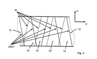
- the mounting direction M of the blades on the rotor base body defined by the blade feet is shown schematically in dashed lines.
- the mounting direction M rectilinear
- the mounting direction M is curved.
- the mounting direction M of the blades is inclined with respect to the axial direction A in a first orientation in the circumferential direction U, wherein the mounting direction M and the axial direction A include a so-called rhomboid angle, which in a curved mounting direction M in the axial direction A changed.
- a radial direction R of the same is furthermore shown.
- FIG. 1 to 4 show different detail views of a rotor according to the invention of a turbomachine according to a first embodiment of the invention, wherein in Fig. 1 3 shows a section of a coupling element designed as an outer cover strip, which is composed of coupling element segments 10, 10 ', 10 "of a plurality of moving blades formed as outer cover tape segments 3 and 4 can be removed, is associated with a radially outer end of a blade 11 of the respective blade.
- the airfoil 11 has a flow inlet edge 12, a flow outlet edge 13 and a suction side 14 and pressure side 15 extending between the flow inlet edge 12 and the flow outlet edge 13.
- the outer shroud segment 10, 10 ', 10 "radially outwardly assigned to the blade 11 of each blade has a width in the circumferential direction U, which is defined by edges extending substantially in the axial direction A.
- radially outer edge 18 and 19 on two opposite sides 16 and 17 of FIG Outer shroud segment 10, 10 ', 10 "in each case one extending substantially in the axial direction A, radially outer edge 18 and 19 and in each case also extending substantially in the axial direction A, radially inner edge 20 and 21.
- the distance between this radially outer edge 18 and 19 and this radially inner edge 20 and 21 determined on the sides 16 and 17 in the radial direction R, the thickness of the outer shroud segment 10, 10 ', 10 ".
- a depth in the axial direction A of the outer shroud segment 10, 10 ', 10 "of each blade is defined by edges extending substantially in the circumferential direction U, again by radially outer edges 22 and 23 and radially inner edges 24 and 25, respectively.
- the edges 22 and 24 are flow-entry-side edges and edges are flow-exit-edges at the edges 23 and 25. The distance between these edges also determines the thickness of the outer shroud segment 10, 10 ', 10 "in the radial direction R, namely on the flow inlet side and on the flow exit side.
- the radially inner edge 20 of the outer shroud segment 10, 10 ', 10 "extending substantially in the axial direction A is opposite the radially outer edge 18, which also extends substantially in the axial direction A. Circumferential direction U before.
- second side 17 of the outer shroud segment 10, 10 ', 10 " at which an immediately adjacent, second blade with its outer shroud segment, namely with a first side thereof, followed, the same is contoured such that the flow outlet side adjacent to the flow outlet edge 13 of the airfoil 11 which extends substantially in the axial direction A extending, radially outer edge 19 of the outer shroud segment 10, 10 ', 10 "relative to the also extending substantially in the axial direction A, radially inner edge 21 in the circumferential direction U protrudes.
- the surface 28, which is concealed from the outside is positioned on the flow inlet side and the surface 30, which is visible from the radial outside, is positioned on the outlet side in the region of the opposite, second side 17 of the outer shroud segment 10, 10', 10 on the other hand, the surface 29, which is concealed radially from the outside, is positioned on the flow exit side and the surface 31, which is visible from the radial outside, is positioned on the flow inlet side.
- the parting lines 26, 27 of these immediately adjacent moving blades extend approximately directly parallel or rectified to the mounting direction M defined over the blade roots of the rotor blades at the rotor base body, whereas at each other circumferential position between two directly adjacent rotor blades the separating lines 26, 27 of these immediately adjacent blades are inclined to the mounting direction M on immediately adjacent sides of the respective coupling element segments 10, 10 'and 10 ".
- the mounting direction M of the rotor blades on the rotor base body is inclined relative to the axial direction A in a first orientation in the circumferential direction U by the so-called rhomboid angle.
- the parting lines 26, 27 in FIG same first orientation as the mounting direction relative to the axial direction A in the circumferential direction U inclined.
- the dividing line 26, 27 inclined in a direction opposite to the first orientation second orientation as the mounting direction M relative to the axial direction in the circumferential direction.
- the above contouring of the coupling element segments 10, 10 'and 10 "of the rotor blades ensures optimal support and thus coupling of the coupling element segments forming the or each coupling element with good mountability of the rotor Coupling element segments 10, 10 'and 10 "are inclined to the mounting direction M, an optimal support and thus coupling of the coupling element segments.
- the radially outer edges 18, 19, which extend essentially in the axial direction A, and the radially inner edges 20, 21, which also extend essentially in the axial direction A, preferably run together with the dividing lines 26, 27, the surfaces 28, 29, 30 and 31 limit.
- the dividing lines 26 and 27 which separate the surfaces 28 and 30 and the surfaces 29 and 31 from each other on the first side 16 and on the second side 17 are executed according to a preferred embodiment of the invention without turning points, wherein the same in the embodiment of Fig. 1 to 4 straight and in Fig. 5 curved. This allows a particularly simple production. Likewise, the substantially extending in the axial direction A edges 18, 19, 20 and 21 are executed without turning points.
- dividing line 26 of the first side 16 is visible from radially outside, whereas the dividing line 27 of the second side 17 is hidden from the outside when viewed radially.
- the dividing lines 26 and 27 of the two sides 16, 17, starting from the flow inlet-side edges to flow-outlet-side edges, run in each case from radially outside to radially inside.
- first side 16 of the outer shroud segment 10 and the opposite, second side 17 of the outer shroud segment 10 are seen in the direction along the respective parting line 26 and 27 viewed from radially outside surfaces 28 and 29 and the visible from radially outside surfaces 30th or 31 each with respect to the radial direction R inclined at an angle.
- the surfaces 28 and 29, which are concealed radially from the outside are inclined by a first angle relative to the radial direction R and the surfaces 30 and 31, which are visible from the radially outside, are inclined by a second angle relative to the radial direction R.
- the first angle and the second angle are equal in magnitude, but have different signs. This is particularly advantageous in terms of manufacturing technology. In contrast to this, however, it is also possible for the first angle and the second angle to be different in magnitude on the first side 16 and on the second side 17, but in turn have different signs.
- FIG. 1 How best Fig. 1 can be removed, as viewed from radially outside both on the first side 16 and on the second side 17 of the outer shroud segment 10 extending substantially in the axial direction A, radially outer edge 18 and 19 and which are substantially in the axial direction A extending, radially inner edge 20 and 21 congruent only at an axial position.
- Fig. 1 to 4 are formed on the sides 16 and 17 of the outer shroud segment 10 surfaces 28 and 29 and the surfaces 30 and 31 respectively formed as a three-dimensional contoured, spatially radially curved. Essentially radially extending edges 32 bounding the outer shroud segment 10 together with the edges 18, 19, 20, 21, 22, 23, 24, and 25 are then curved.
- these surfaces 28, 29, 30 and 31 are designed as two-dimensionally contoured, flat surfaces. Essentially radially extending edges 32 bounding the outer shroud segment 10 together with the edges 18, 19, 20, 21, 22, 23, 24 and 25 are then straight.
- the embodiment differs from the Fig. 5 from the embodiment of Fig. 1 to 4 only in that the mounting direction M of the blades is not rectilinear but curved.
- the embodiment of the Fig. 5 with the embodiment of Fig. 1 to 4 match, so that reference is made to the above statements.
- a rotor according to the invention has no outer shroud segment but exclusively at least one coupling element segment embodied as an inner coupling element segment. Furthermore, it is possible for the parting line 26 of the first side 16 to be concealed from radially outside, whereas the parting line 27 of the second side 17 is visible from radially outside.
Landscapes
- Engineering & Computer Science (AREA)
- Mechanical Engineering (AREA)
- General Engineering & Computer Science (AREA)
- Structures Of Non-Positive Displacement Pumps (AREA)
- Turbine Rotor Nozzle Sealing (AREA)
Applications Claiming Priority (1)
| Application Number | Priority Date | Filing Date | Title |
|---|---|---|---|
| DE102010031213A DE102010031213A1 (de) | 2010-07-12 | 2010-07-12 | Rotor einer Turbomaschine |
Publications (3)
| Publication Number | Publication Date |
|---|---|
| EP2410131A2 true EP2410131A2 (fr) | 2012-01-25 |
| EP2410131A3 EP2410131A3 (fr) | 2017-08-02 |
| EP2410131B1 EP2410131B1 (fr) | 2018-08-15 |
Family
ID=43901478
Family Applications (1)
| Application Number | Title | Priority Date | Filing Date |
|---|---|---|---|
| EP11161987.0A Not-in-force EP2410131B1 (fr) | 2010-07-12 | 2011-04-12 | Rotor d'une turbomachine |
Country Status (5)
| Country | Link |
|---|---|
| US (1) | US8974186B2 (fr) |
| EP (1) | EP2410131B1 (fr) |
| JP (1) | JP5274625B2 (fr) |
| CN (1) | CN102330572B (fr) |
| DE (1) | DE102010031213A1 (fr) |
Cited By (1)
| Publication number | Priority date | Publication date | Assignee | Title |
|---|---|---|---|---|
| EP2578801B1 (fr) * | 2011-10-07 | 2021-04-07 | MTU Aero Engines GmbH | Talons d'aube pour une turbomachine |
Families Citing this family (5)
| Publication number | Priority date | Publication date | Assignee | Title |
|---|---|---|---|---|
| US9347326B2 (en) * | 2012-11-02 | 2016-05-24 | General Electric Company | Integral cover bucket assembly |
| WO2016181911A1 (fr) * | 2015-05-08 | 2016-11-17 | 株式会社リコー | Élément de conversion photoélectrique |
| WO2016184685A1 (fr) | 2015-05-20 | 2016-11-24 | Man Diesel & Turbo Se | Procédé de fabrication d'un rotor de turbomachine |
| IT201900017171A1 (it) * | 2019-09-25 | 2021-03-25 | Ge Avio Srl | Protezioni delle punte delle pale di turbina desintonizzate |
| CN114382555A (zh) * | 2020-10-16 | 2022-04-22 | 中国航发商用航空发动机有限责任公司 | 导叶缘板、导叶、涡轮导向器及导叶缘板的设计方法 |
Citations (6)
| Publication number | Priority date | Publication date | Assignee | Title |
|---|---|---|---|---|
| DE1122551B (de) | 1960-05-09 | 1962-01-25 | Sulzer Ag | Befestigung austenitischer Schaufeln in einer Umfangsnut eines ferritischen Schaufeltraegers |
| DE1159965B (de) | 1961-08-10 | 1963-12-27 | Bbc Brown Boveri & Cie | Einrichtung zur Schwingungsdaempfung an einem Turbinen- oder Verdichter-Schaufelkranz |
| GB2072760A (en) | 1980-03-29 | 1981-10-07 | Rolls Royce | Shrouded turbine rotor blade |
| US4400915A (en) | 1980-06-02 | 1983-08-30 | United Technologies Corporation | Fixture for restoring a face on the shroud of a rotor blade |
| DE4015206C1 (fr) | 1990-05-11 | 1991-10-17 | Mtu Muenchen Gmbh | |
| EP1134359A2 (fr) | 2000-03-14 | 2001-09-19 | MAN Turbomaschinen AG GHH BORSIG | Verrou pour aube de turbomachine et sa methode de fabrication |
Family Cites Families (11)
| Publication number | Priority date | Publication date | Assignee | Title |
|---|---|---|---|---|
| AT242717B (de) | 1961-08-10 | 1965-10-11 | Bbc Brown Boveri & Cie | Deckbandbeschauflung für Turbinen oder Verdichter |
| US3923420A (en) * | 1973-04-30 | 1975-12-02 | Gen Electric | Blade platform with friction damping interlock |
| US5001830A (en) * | 1989-10-23 | 1991-03-26 | Westinghouse Electric Corp. | Method for assembling side entry control stage blades in a steam turbine |
| JPH0791206A (ja) * | 1993-09-24 | 1995-04-04 | Mitsubishi Heavy Ind Ltd | 回転機械動翼のダンパ構造 |
| JPH09209703A (ja) * | 1996-01-31 | 1997-08-12 | Mitsubishi Heavy Ind Ltd | インテグラルシュラウド翼 |
| US6910854B2 (en) * | 2002-10-08 | 2005-06-28 | United Technologies Corporation | Leak resistant vane cluster |
| JP4335771B2 (ja) * | 2004-09-16 | 2009-09-30 | 株式会社日立製作所 | タービン動翼及びタービン設備 |
| JP4869616B2 (ja) * | 2005-04-01 | 2012-02-08 | 株式会社日立製作所 | 蒸気タービン動翼と蒸気タービンロータ及びそれを用いた蒸気タービン並びにその発電プラント |
| JP2007064074A (ja) * | 2005-08-30 | 2007-03-15 | Toshiba Corp | 軸流タービン |
| EP1961918A1 (fr) | 2007-02-21 | 2008-08-27 | ABB Turbo Systems AG | Roue de turbine |
| DE102009029587A1 (de) * | 2009-09-18 | 2011-03-24 | Man Diesel & Turbo Se | Rotor einer Turbomaschine |
-
2010
- 2010-07-12 DE DE102010031213A patent/DE102010031213A1/de not_active Withdrawn
-
2011
- 2011-04-12 EP EP11161987.0A patent/EP2410131B1/fr not_active Not-in-force
- 2011-07-11 JP JP2011152956A patent/JP5274625B2/ja not_active Expired - Fee Related
- 2011-07-11 US US13/180,363 patent/US8974186B2/en not_active Expired - Fee Related
- 2011-07-12 CN CN201110193939.0A patent/CN102330572B/zh not_active Expired - Fee Related
Patent Citations (6)
| Publication number | Priority date | Publication date | Assignee | Title |
|---|---|---|---|---|
| DE1122551B (de) | 1960-05-09 | 1962-01-25 | Sulzer Ag | Befestigung austenitischer Schaufeln in einer Umfangsnut eines ferritischen Schaufeltraegers |
| DE1159965B (de) | 1961-08-10 | 1963-12-27 | Bbc Brown Boveri & Cie | Einrichtung zur Schwingungsdaempfung an einem Turbinen- oder Verdichter-Schaufelkranz |
| GB2072760A (en) | 1980-03-29 | 1981-10-07 | Rolls Royce | Shrouded turbine rotor blade |
| US4400915A (en) | 1980-06-02 | 1983-08-30 | United Technologies Corporation | Fixture for restoring a face on the shroud of a rotor blade |
| DE4015206C1 (fr) | 1990-05-11 | 1991-10-17 | Mtu Muenchen Gmbh | |
| EP1134359A2 (fr) | 2000-03-14 | 2001-09-19 | MAN Turbomaschinen AG GHH BORSIG | Verrou pour aube de turbomachine et sa methode de fabrication |
Cited By (1)
| Publication number | Priority date | Publication date | Assignee | Title |
|---|---|---|---|---|
| EP2578801B1 (fr) * | 2011-10-07 | 2021-04-07 | MTU Aero Engines GmbH | Talons d'aube pour une turbomachine |
Also Published As
| Publication number | Publication date |
|---|---|
| JP2012021529A (ja) | 2012-02-02 |
| DE102010031213A1 (de) | 2012-01-12 |
| JP5274625B2 (ja) | 2013-08-28 |
| EP2410131B1 (fr) | 2018-08-15 |
| CN102330572B (zh) | 2014-07-09 |
| US20120009067A1 (en) | 2012-01-12 |
| US8974186B2 (en) | 2015-03-10 |
| CN102330572A (zh) | 2012-01-25 |
| EP2410131A3 (fr) | 2017-08-02 |
Similar Documents
| Publication | Publication Date | Title |
|---|---|---|
| EP2478186B1 (fr) | Rotor de turbomachine | |
| EP2473743B1 (fr) | Aube mobile de compresseur pour un compresseur axial | |
| EP2647795B1 (fr) | Système d'étanchéité pour turbomachine | |
| EP2927503B1 (fr) | Compresseur de turbine à gaz, moteur d'avion et méthode de dimensionnement | |
| DE102007037924A1 (de) | Strömungsarbeitsmaschine mit Ringkanalwandausnehmung | |
| DE102008011644A1 (de) | Gehäusestrukturierung für Axialverdichter im Nabenbereich | |
| EP2921716B1 (fr) | Groupe de série d'aubes | |
| EP3536974B1 (fr) | Compresseur de turbine à gaz | |
| EP3999717B1 (fr) | Élément intermédiaire pour une connexion aube-disque de rotor pour le rotor d'une turbomachine, rotor pour une turbomachine et turbomachine | |
| EP2410131B1 (fr) | Rotor d'une turbomachine | |
| EP3409899B1 (fr) | Dispositif de joint d'étanchéité pourvu de tôle d'étanchéité assemblée par soudage, turbomachine et procédé de fabrication | |
| EP2647796A1 (fr) | Système d'étanchéité pour turbomachine | |
| EP2607625A1 (fr) | Turbomachine et étage de turbomachine | |
| EP3401504B1 (fr) | Grille d'aube | |
| EP2787178B1 (fr) | Ensemble d'aube directrice | |
| EP3358135B1 (fr) | Contournage d'une plate-forme de grille d'aube | |
| EP3388626B1 (fr) | Contournage d'une plate-forme de grille d'aube | |
| EP2696042A1 (fr) | Turbomachine avec au moins un stator | |
| EP3428391B1 (fr) | Grille d'aube d'une turbomachine | |
| EP2650475B1 (fr) | Pale pour une turbomachine, agencement d'aubes ainsi que la turbomachine | |
| EP2294285A2 (fr) | Grille d'aubes pour une turbomachine et turbomachine comportant une telle grille | |
| EP3954875B1 (fr) | Aube directrice, étage de compresseur pour une turbine à gaz, turbomachine et procédé pour exploiter une turbomachine | |
| EP3719258B1 (fr) | Aube mobile d'une turbomachine | |
| EP4089264A1 (fr) | Agencement d'aubes pour turbines à gaz | |
| DE102019220028B4 (de) | Axialturbine |
Legal Events
| Date | Code | Title | Description |
|---|---|---|---|
| AK | Designated contracting states |
Kind code of ref document: A2 Designated state(s): AL AT BE BG CH CY CZ DE DK EE ES FI FR GB GR HR HU IE IS IT LI LT LU LV MC MK MT NL NO PL PT RO RS SE SI SK SM TR |
|
| AX | Request for extension of the european patent |
Extension state: BA ME |
|
| PUAI | Public reference made under article 153(3) epc to a published international application that has entered the european phase |
Free format text: ORIGINAL CODE: 0009012 |
|
| PUAL | Search report despatched |
Free format text: ORIGINAL CODE: 0009013 |
|
| AK | Designated contracting states |
Kind code of ref document: A3 Designated state(s): AL AT BE BG CH CY CZ DE DK EE ES FI FR GB GR HR HU IE IS IT LI LT LU LV MC MK MT NL NO PL PT RO RS SE SI SK SM TR |
|
| AX | Request for extension of the european patent |
Extension state: BA ME |
|
| RIC1 | Information provided on ipc code assigned before grant |
Ipc: F01D 5/22 20060101AFI20170626BHEP |
|
| STAA | Information on the status of an ep patent application or granted ep patent |
Free format text: STATUS: REQUEST FOR EXAMINATION WAS MADE |
|
| 17P | Request for examination filed |
Effective date: 20170828 |
|
| RBV | Designated contracting states (corrected) |
Designated state(s): AL AT BE BG CH CY CZ DE DK EE ES FI FR GB GR HR HU IE IS IT LI LT LU LV MC MK MT NL NO PL PT RO RS SE SI SK SM TR |
|
| GRAP | Despatch of communication of intention to grant a patent |
Free format text: ORIGINAL CODE: EPIDOSNIGR1 |
|
| STAA | Information on the status of an ep patent application or granted ep patent |
Free format text: STATUS: GRANT OF PATENT IS INTENDED |
|
| INTG | Intention to grant announced |
Effective date: 20180323 |
|
| GRAS | Grant fee paid |
Free format text: ORIGINAL CODE: EPIDOSNIGR3 |
|
| GRAA | (expected) grant |
Free format text: ORIGINAL CODE: 0009210 |
|
| STAA | Information on the status of an ep patent application or granted ep patent |
Free format text: STATUS: THE PATENT HAS BEEN GRANTED |
|
| AK | Designated contracting states |
Kind code of ref document: B1 Designated state(s): AL AT BE BG CH CY CZ DE DK EE ES FI FR GB GR HR HU IE IS IT LI LT LU LV MC MK MT NL NO PL PT RO RS SE SI SK SM TR |
|
| REG | Reference to a national code |
Ref country code: CH Ref legal event code: EP Ref country code: GB Ref legal event code: FG4D Free format text: NOT ENGLISH Ref country code: AT Ref legal event code: REF Ref document number: 1030001 Country of ref document: AT Kind code of ref document: T Effective date: 20180815 |
|
| REG | Reference to a national code |
Ref country code: IE Ref legal event code: FG4D Free format text: LANGUAGE OF EP DOCUMENT: GERMAN |
|
| REG | Reference to a national code |
Ref country code: DE Ref legal event code: R096 Ref document number: 502011014589 Country of ref document: DE |
|
| REG | Reference to a national code |
Ref country code: CH Ref legal event code: NV Representative=s name: E. BLUM AND CO. AG PATENT- UND MARKENANWAELTE , CH Ref country code: CH Ref legal event code: PFA Owner name: MAN ENERGY SOLUTIONS SE, DE Free format text: FORMER OWNER: MAN DIESEL AND TURBO SE, DE |
|
| REG | Reference to a national code |
Ref country code: SE Ref legal event code: TRGR |
|
| REG | Reference to a national code |
Ref country code: NL Ref legal event code: MP Effective date: 20180815 |
|
| RAP2 | Party data changed (patent owner data changed or rights of a patent transferred) |
Owner name: MAN ENERGY SOLUTIONS SE |
|
| REG | Reference to a national code |
Ref country code: LT Ref legal event code: MG4D |
|
| PG25 | Lapsed in a contracting state [announced via postgrant information from national office to epo] |
Ref country code: GR Free format text: LAPSE BECAUSE OF FAILURE TO SUBMIT A TRANSLATION OF THE DESCRIPTION OR TO PAY THE FEE WITHIN THE PRESCRIBED TIME-LIMIT Effective date: 20181116 Ref country code: NO Free format text: LAPSE BECAUSE OF FAILURE TO SUBMIT A TRANSLATION OF THE DESCRIPTION OR TO PAY THE FEE WITHIN THE PRESCRIBED TIME-LIMIT Effective date: 20181115 Ref country code: NL Free format text: LAPSE BECAUSE OF FAILURE TO SUBMIT A TRANSLATION OF THE DESCRIPTION OR TO PAY THE FEE WITHIN THE PRESCRIBED TIME-LIMIT Effective date: 20180815 Ref country code: LT Free format text: LAPSE BECAUSE OF FAILURE TO SUBMIT A TRANSLATION OF THE DESCRIPTION OR TO PAY THE FEE WITHIN THE PRESCRIBED TIME-LIMIT Effective date: 20180815 Ref country code: BG Free format text: LAPSE BECAUSE OF FAILURE TO SUBMIT A TRANSLATION OF THE DESCRIPTION OR TO PAY THE FEE WITHIN THE PRESCRIBED TIME-LIMIT Effective date: 20181115 Ref country code: FI Free format text: LAPSE BECAUSE OF FAILURE TO SUBMIT A TRANSLATION OF THE DESCRIPTION OR TO PAY THE FEE WITHIN THE PRESCRIBED TIME-LIMIT Effective date: 20180815 Ref country code: IS Free format text: LAPSE BECAUSE OF FAILURE TO SUBMIT A TRANSLATION OF THE DESCRIPTION OR TO PAY THE FEE WITHIN THE PRESCRIBED TIME-LIMIT Effective date: 20181215 Ref country code: RS Free format text: LAPSE BECAUSE OF FAILURE TO SUBMIT A TRANSLATION OF THE DESCRIPTION OR TO PAY THE FEE WITHIN THE PRESCRIBED TIME-LIMIT Effective date: 20180815 |
|
| PG25 | Lapsed in a contracting state [announced via postgrant information from national office to epo] |
Ref country code: AL Free format text: LAPSE BECAUSE OF FAILURE TO SUBMIT A TRANSLATION OF THE DESCRIPTION OR TO PAY THE FEE WITHIN THE PRESCRIBED TIME-LIMIT Effective date: 20180815 Ref country code: ES Free format text: LAPSE BECAUSE OF FAILURE TO SUBMIT A TRANSLATION OF THE DESCRIPTION OR TO PAY THE FEE WITHIN THE PRESCRIBED TIME-LIMIT Effective date: 20180815 Ref country code: LV Free format text: LAPSE BECAUSE OF FAILURE TO SUBMIT A TRANSLATION OF THE DESCRIPTION OR TO PAY THE FEE WITHIN THE PRESCRIBED TIME-LIMIT Effective date: 20180815 Ref country code: HR Free format text: LAPSE BECAUSE OF FAILURE TO SUBMIT A TRANSLATION OF THE DESCRIPTION OR TO PAY THE FEE WITHIN THE PRESCRIBED TIME-LIMIT Effective date: 20180815 |
|
| REG | Reference to a national code |
Ref country code: DE Ref legal event code: R081 Ref document number: 502011014589 Country of ref document: DE Owner name: MAN ENERGY SOLUTIONS SE, DE Free format text: FORMER OWNER: MAN DIESEL & TURBO SE, 86153 AUGSBURG, DE |
|
| PG25 | Lapsed in a contracting state [announced via postgrant information from national office to epo] |
Ref country code: PL Free format text: LAPSE BECAUSE OF FAILURE TO SUBMIT A TRANSLATION OF THE DESCRIPTION OR TO PAY THE FEE WITHIN THE PRESCRIBED TIME-LIMIT Effective date: 20180815 Ref country code: EE Free format text: LAPSE BECAUSE OF FAILURE TO SUBMIT A TRANSLATION OF THE DESCRIPTION OR TO PAY THE FEE WITHIN THE PRESCRIBED TIME-LIMIT Effective date: 20180815 Ref country code: RO Free format text: LAPSE BECAUSE OF FAILURE TO SUBMIT A TRANSLATION OF THE DESCRIPTION OR TO PAY THE FEE WITHIN THE PRESCRIBED TIME-LIMIT Effective date: 20180815 Ref country code: CZ Free format text: LAPSE BECAUSE OF FAILURE TO SUBMIT A TRANSLATION OF THE DESCRIPTION OR TO PAY THE FEE WITHIN THE PRESCRIBED TIME-LIMIT Effective date: 20180815 |
|
| REG | Reference to a national code |
Ref country code: DE Ref legal event code: R097 Ref document number: 502011014589 Country of ref document: DE |
|
| PG25 | Lapsed in a contracting state [announced via postgrant information from national office to epo] |
Ref country code: SK Free format text: LAPSE BECAUSE OF FAILURE TO SUBMIT A TRANSLATION OF THE DESCRIPTION OR TO PAY THE FEE WITHIN THE PRESCRIBED TIME-LIMIT Effective date: 20180815 Ref country code: SM Free format text: LAPSE BECAUSE OF FAILURE TO SUBMIT A TRANSLATION OF THE DESCRIPTION OR TO PAY THE FEE WITHIN THE PRESCRIBED TIME-LIMIT Effective date: 20180815 Ref country code: DK Free format text: LAPSE BECAUSE OF FAILURE TO SUBMIT A TRANSLATION OF THE DESCRIPTION OR TO PAY THE FEE WITHIN THE PRESCRIBED TIME-LIMIT Effective date: 20180815 |
|
| PLBE | No opposition filed within time limit |
Free format text: ORIGINAL CODE: 0009261 |
|
| STAA | Information on the status of an ep patent application or granted ep patent |
Free format text: STATUS: NO OPPOSITION FILED WITHIN TIME LIMIT |
|
| 26N | No opposition filed |
Effective date: 20190516 |
|
| PG25 | Lapsed in a contracting state [announced via postgrant information from national office to epo] |
Ref country code: SI Free format text: LAPSE BECAUSE OF FAILURE TO SUBMIT A TRANSLATION OF THE DESCRIPTION OR TO PAY THE FEE WITHIN THE PRESCRIBED TIME-LIMIT Effective date: 20180815 |
|
| REG | Reference to a national code |
Ref country code: BE Ref legal event code: MM Effective date: 20190430 |
|
| PG25 | Lapsed in a contracting state [announced via postgrant information from national office to epo] |
Ref country code: MC Free format text: LAPSE BECAUSE OF FAILURE TO SUBMIT A TRANSLATION OF THE DESCRIPTION OR TO PAY THE FEE WITHIN THE PRESCRIBED TIME-LIMIT Effective date: 20180815 Ref country code: LU Free format text: LAPSE BECAUSE OF NON-PAYMENT OF DUE FEES Effective date: 20190412 |
|
| PG25 | Lapsed in a contracting state [announced via postgrant information from national office to epo] |
Ref country code: BE Free format text: LAPSE BECAUSE OF NON-PAYMENT OF DUE FEES Effective date: 20190430 |
|
| PG25 | Lapsed in a contracting state [announced via postgrant information from national office to epo] |
Ref country code: TR Free format text: LAPSE BECAUSE OF FAILURE TO SUBMIT A TRANSLATION OF THE DESCRIPTION OR TO PAY THE FEE WITHIN THE PRESCRIBED TIME-LIMIT Effective date: 20180815 |
|
| PG25 | Lapsed in a contracting state [announced via postgrant information from national office to epo] |
Ref country code: IE Free format text: LAPSE BECAUSE OF NON-PAYMENT OF DUE FEES Effective date: 20190412 |
|
| PG25 | Lapsed in a contracting state [announced via postgrant information from national office to epo] |
Ref country code: PT Free format text: LAPSE BECAUSE OF FAILURE TO SUBMIT A TRANSLATION OF THE DESCRIPTION OR TO PAY THE FEE WITHIN THE PRESCRIBED TIME-LIMIT Effective date: 20181215 |
|
| PGFP | Annual fee paid to national office [announced via postgrant information from national office to epo] |
Ref country code: FR Payment date: 20200420 Year of fee payment: 10 Ref country code: CH Payment date: 20200420 Year of fee payment: 10 Ref country code: DE Payment date: 20200420 Year of fee payment: 10 |
|
| REG | Reference to a national code |
Ref country code: AT Ref legal event code: MM01 Ref document number: 1030001 Country of ref document: AT Kind code of ref document: T Effective date: 20190412 |
|
| PGFP | Annual fee paid to national office [announced via postgrant information from national office to epo] |
Ref country code: IT Payment date: 20200428 Year of fee payment: 10 Ref country code: GB Payment date: 20200427 Year of fee payment: 10 Ref country code: SE Payment date: 20200427 Year of fee payment: 10 |
|
| PG25 | Lapsed in a contracting state [announced via postgrant information from national office to epo] |
Ref country code: AT Free format text: LAPSE BECAUSE OF NON-PAYMENT OF DUE FEES Effective date: 20190412 |
|
| PG25 | Lapsed in a contracting state [announced via postgrant information from national office to epo] |
Ref country code: CY Free format text: LAPSE BECAUSE OF FAILURE TO SUBMIT A TRANSLATION OF THE DESCRIPTION OR TO PAY THE FEE WITHIN THE PRESCRIBED TIME-LIMIT Effective date: 20180815 |
|
| PG25 | Lapsed in a contracting state [announced via postgrant information from national office to epo] |
Ref country code: MT Free format text: LAPSE BECAUSE OF FAILURE TO SUBMIT A TRANSLATION OF THE DESCRIPTION OR TO PAY THE FEE WITHIN THE PRESCRIBED TIME-LIMIT Effective date: 20180815 Ref country code: HU Free format text: LAPSE BECAUSE OF FAILURE TO SUBMIT A TRANSLATION OF THE DESCRIPTION OR TO PAY THE FEE WITHIN THE PRESCRIBED TIME-LIMIT; INVALID AB INITIO Effective date: 20110412 |
|
| REG | Reference to a national code |
Ref country code: DE Ref legal event code: R119 Ref document number: 502011014589 Country of ref document: DE |
|
| REG | Reference to a national code |
Ref country code: SE Ref legal event code: EUG |
|
| GBPC | Gb: european patent ceased through non-payment of renewal fee |
Effective date: 20210412 |
|
| PG25 | Lapsed in a contracting state [announced via postgrant information from national office to epo] |
Ref country code: CH Free format text: LAPSE BECAUSE OF NON-PAYMENT OF DUE FEES Effective date: 20210430 Ref country code: LI Free format text: LAPSE BECAUSE OF NON-PAYMENT OF DUE FEES Effective date: 20210430 Ref country code: GB Free format text: LAPSE BECAUSE OF NON-PAYMENT OF DUE FEES Effective date: 20210412 Ref country code: FR Free format text: LAPSE BECAUSE OF NON-PAYMENT OF DUE FEES Effective date: 20210430 Ref country code: SE Free format text: LAPSE BECAUSE OF NON-PAYMENT OF DUE FEES Effective date: 20210413 Ref country code: DE Free format text: LAPSE BECAUSE OF NON-PAYMENT OF DUE FEES Effective date: 20211103 |
|
| PG25 | Lapsed in a contracting state [announced via postgrant information from national office to epo] |
Ref country code: MK Free format text: LAPSE BECAUSE OF FAILURE TO SUBMIT A TRANSLATION OF THE DESCRIPTION OR TO PAY THE FEE WITHIN THE PRESCRIBED TIME-LIMIT Effective date: 20180815 |
|
| PG25 | Lapsed in a contracting state [announced via postgrant information from national office to epo] |
Ref country code: IT Free format text: LAPSE BECAUSE OF NON-PAYMENT OF DUE FEES Effective date: 20200412 |
|
| PG25 | Lapsed in a contracting state [announced via postgrant information from national office to epo] |
Ref country code: IT Free format text: LAPSE BECAUSE OF NON-PAYMENT OF DUE FEES Effective date: 20210412 |