EP1898064B1 - Verbrennungsmotor mit fremdzündung und direkteinspritzung - Google Patents
Verbrennungsmotor mit fremdzündung und direkteinspritzung Download PDFInfo
- Publication number
- EP1898064B1 EP1898064B1 EP06747318A EP06747318A EP1898064B1 EP 1898064 B1 EP1898064 B1 EP 1898064B1 EP 06747318 A EP06747318 A EP 06747318A EP 06747318 A EP06747318 A EP 06747318A EP 1898064 B1 EP1898064 B1 EP 1898064B1
- Authority
- EP
- European Patent Office
- Prior art keywords
- fuel
- cavity
- tumble flow
- internal combustion
- combustion engine
- Prior art date
- Legal status (The legal status is an assumption and is not a legal conclusion. Google has not performed a legal analysis and makes no representation as to the accuracy of the status listed.)
- Not-in-force
Links
- 238000002485 combustion reaction Methods 0.000 title claims description 73
- 238000002347 injection Methods 0.000 title claims description 38
- 239000007924 injection Substances 0.000 title claims description 38
- 239000000446 fuel Substances 0.000 claims description 230
- 239000000203 mixture Substances 0.000 claims description 32
- 230000006835 compression Effects 0.000 claims description 13
- 238000007906 compression Methods 0.000 claims description 13
- 239000007921 spray Substances 0.000 description 9
- 230000000630 rising effect Effects 0.000 description 3
- 238000011144 upstream manufacturing Methods 0.000 description 3
- 230000015572 biosynthetic process Effects 0.000 description 2
- 230000000149 penetrating effect Effects 0.000 description 2
- 230000000644 propagated effect Effects 0.000 description 2
- 238000009841 combustion method Methods 0.000 description 1
- 230000003116 impacting effect Effects 0.000 description 1
Images

Classifications
-
- F—MECHANICAL ENGINEERING; LIGHTING; HEATING; WEAPONS; BLASTING
- F02—COMBUSTION ENGINES; HOT-GAS OR COMBUSTION-PRODUCT ENGINE PLANTS
- F02B—INTERNAL-COMBUSTION PISTON ENGINES; COMBUSTION ENGINES IN GENERAL
- F02B23/00—Other engines characterised by special shape or construction of combustion chambers to improve operation
- F02B23/08—Other engines characterised by special shape or construction of combustion chambers to improve operation with positive ignition
- F02B23/10—Other engines characterised by special shape or construction of combustion chambers to improve operation with positive ignition with separate admission of air and fuel into cylinder
- F02B23/101—Other engines characterised by special shape or construction of combustion chambers to improve operation with positive ignition with separate admission of air and fuel into cylinder the injector being placed on or close to the cylinder centre axis, e.g. with mixture formation using spray guided concepts
-
- F—MECHANICAL ENGINEERING; LIGHTING; HEATING; WEAPONS; BLASTING
- F02—COMBUSTION ENGINES; HOT-GAS OR COMBUSTION-PRODUCT ENGINE PLANTS
- F02B—INTERNAL-COMBUSTION PISTON ENGINES; COMBUSTION ENGINES IN GENERAL
- F02B23/00—Other engines characterised by special shape or construction of combustion chambers to improve operation
- F02B23/08—Other engines characterised by special shape or construction of combustion chambers to improve operation with positive ignition
- F02B23/10—Other engines characterised by special shape or construction of combustion chambers to improve operation with positive ignition with separate admission of air and fuel into cylinder
-
- F—MECHANICAL ENGINEERING; LIGHTING; HEATING; WEAPONS; BLASTING
- F02—COMBUSTION ENGINES; HOT-GAS OR COMBUSTION-PRODUCT ENGINE PLANTS
- F02B—INTERNAL-COMBUSTION PISTON ENGINES; COMBUSTION ENGINES IN GENERAL
- F02B17/00—Engines characterised by means for effecting stratification of charge in cylinders
- F02B17/005—Engines characterised by means for effecting stratification of charge in cylinders having direct injection in the combustion chamber
-
- F—MECHANICAL ENGINEERING; LIGHTING; HEATING; WEAPONS; BLASTING
- F02—COMBUSTION ENGINES; HOT-GAS OR COMBUSTION-PRODUCT ENGINE PLANTS
- F02B—INTERNAL-COMBUSTION PISTON ENGINES; COMBUSTION ENGINES IN GENERAL
- F02B25/00—Engines characterised by using fresh charge for scavenging cylinders
- F02B25/14—Engines characterised by using fresh charge for scavenging cylinders using reverse-flow scavenging, e.g. with both outlet and inlet ports arranged near bottom of piston stroke
- F02B25/18—Engines characterised by using fresh charge for scavenging cylinders using reverse-flow scavenging, e.g. with both outlet and inlet ports arranged near bottom of piston stroke the charge flowing upward essentially along cylinder wall adjacent the inlet ports, e.g. by means of deflection rib on piston
-
- F—MECHANICAL ENGINEERING; LIGHTING; HEATING; WEAPONS; BLASTING
- F02—COMBUSTION ENGINES; HOT-GAS OR COMBUSTION-PRODUCT ENGINE PLANTS
- F02F—CYLINDERS, PISTONS OR CASINGS, FOR COMBUSTION ENGINES; ARRANGEMENTS OF SEALINGS IN COMBUSTION ENGINES
- F02F3/00—Pistons
- F02F3/26—Pistons having combustion chamber in piston head
-
- F—MECHANICAL ENGINEERING; LIGHTING; HEATING; WEAPONS; BLASTING
- F02—COMBUSTION ENGINES; HOT-GAS OR COMBUSTION-PRODUCT ENGINE PLANTS
- F02M—SUPPLYING COMBUSTION ENGINES IN GENERAL WITH COMBUSTIBLE MIXTURES OR CONSTITUENTS THEREOF
- F02M61/00—Fuel-injectors not provided for in groups F02M39/00 - F02M57/00 or F02M67/00
- F02M61/16—Details not provided for in, or of interest apart from, the apparatus of groups F02M61/02 - F02M61/14
- F02M61/18—Injection nozzles, e.g. having valve seats; Details of valve member seated ends, not otherwise provided for
-
- F—MECHANICAL ENGINEERING; LIGHTING; HEATING; WEAPONS; BLASTING
- F02—COMBUSTION ENGINES; HOT-GAS OR COMBUSTION-PRODUCT ENGINE PLANTS
- F02P—IGNITION, OTHER THAN COMPRESSION IGNITION, FOR INTERNAL-COMBUSTION ENGINES; TESTING OF IGNITION TIMING IN COMPRESSION-IGNITION ENGINES
- F02P13/00—Sparking plugs structurally combined with other parts of internal-combustion engines
-
- F—MECHANICAL ENGINEERING; LIGHTING; HEATING; WEAPONS; BLASTING
- F02—COMBUSTION ENGINES; HOT-GAS OR COMBUSTION-PRODUCT ENGINE PLANTS
- F02B—INTERNAL-COMBUSTION PISTON ENGINES; COMBUSTION ENGINES IN GENERAL
- F02B23/00—Other engines characterised by special shape or construction of combustion chambers to improve operation
- F02B23/08—Other engines characterised by special shape or construction of combustion chambers to improve operation with positive ignition
- F02B23/10—Other engines characterised by special shape or construction of combustion chambers to improve operation with positive ignition with separate admission of air and fuel into cylinder
- F02B2023/106—Tumble flow, i.e. the axis of rotation of the main charge flow motion is horizontal
-
- F—MECHANICAL ENGINEERING; LIGHTING; HEATING; WEAPONS; BLASTING
- F02—COMBUSTION ENGINES; HOT-GAS OR COMBUSTION-PRODUCT ENGINE PLANTS
- F02B—INTERNAL-COMBUSTION PISTON ENGINES; COMBUSTION ENGINES IN GENERAL
- F02B23/00—Other engines characterised by special shape or construction of combustion chambers to improve operation
- F02B23/08—Other engines characterised by special shape or construction of combustion chambers to improve operation with positive ignition
- F02B23/10—Other engines characterised by special shape or construction of combustion chambers to improve operation with positive ignition with separate admission of air and fuel into cylinder
- F02B2023/106—Tumble flow, i.e. the axis of rotation of the main charge flow motion is horizontal
- F02B2023/107—Reverse tumble flow, e.g. having substantially vertical intake ports
-
- F—MECHANICAL ENGINEERING; LIGHTING; HEATING; WEAPONS; BLASTING
- F02—COMBUSTION ENGINES; HOT-GAS OR COMBUSTION-PRODUCT ENGINE PLANTS
- F02B—INTERNAL-COMBUSTION PISTON ENGINES; COMBUSTION ENGINES IN GENERAL
- F02B75/00—Other engines
- F02B75/12—Other methods of operation
- F02B2075/125—Direct injection in the combustion chamber for spark ignition engines, i.e. not in pre-combustion chamber
-
- F—MECHANICAL ENGINEERING; LIGHTING; HEATING; WEAPONS; BLASTING
- F02—COMBUSTION ENGINES; HOT-GAS OR COMBUSTION-PRODUCT ENGINE PLANTS
- F02D—CONTROLLING COMBUSTION ENGINES
- F02D41/00—Electrical control of supply of combustible mixture or its constituents
- F02D41/30—Controlling fuel injection
- F02D41/38—Controlling fuel injection of the high pressure type
- F02D2041/389—Controlling fuel injection of the high pressure type for injecting directly into the cylinder
-
- Y—GENERAL TAGGING OF NEW TECHNOLOGICAL DEVELOPMENTS; GENERAL TAGGING OF CROSS-SECTIONAL TECHNOLOGIES SPANNING OVER SEVERAL SECTIONS OF THE IPC; TECHNICAL SUBJECTS COVERED BY FORMER USPC CROSS-REFERENCE ART COLLECTIONS [XRACs] AND DIGESTS
- Y02—TECHNOLOGIES OR APPLICATIONS FOR MITIGATION OR ADAPTATION AGAINST CLIMATE CHANGE
- Y02T—CLIMATE CHANGE MITIGATION TECHNOLOGIES RELATED TO TRANSPORTATION
- Y02T10/00—Road transport of goods or passengers
- Y02T10/10—Internal combustion engine [ICE] based vehicles
- Y02T10/12—Improving ICE efficiencies
Definitions
- the present invention relates to a direct fuel injection-type spark-ignition internal combustion engine.
- the fuel injector injects fuel in a hollow conical shape, but even if just injecting fuel in this way, the injected fuel will not form a good combustible air-fuel mixture sufficiently mixed with intake air during its flight before reaching the piston top face or cylinder bore and good stratified combustion can not be realized as designed.
- an object of the present invention is to provide a direct fuel injection-type spark-ignition internal combustion engine reliably making the fuel injected from the fuel injector a good combustible air-fuel mixture during flight and igniting and burning this combustible air-fuel mixture by a spark plug to enable realization of good stratified combustion.
- the direct fuel injection-type spark-ignition internal combustion engine described in claim 1 of the present invention is provided with a fuel injector for directly injecting fuel into a cylinder, a spark plug positioning a spark gap in a flight path of fuel injected from the fuel injector, and a cavity formed in a piston top face, wherein at the time of stratified combustion, the fuel injector injects substantially all of the fuel in a direction merging with a tumble flow, swirling in a longitudinal direction along the cavity at the compression stroke, along the swirl direction of the tumble flow and uses the spark plug to ignite the fuel while the fuel at the end period of injection is passing through the spark gap.
- the direct fuel injection-type spark-ignition internal combustion engine described in claim 2 of the present invention provides the direct fuel injection-type spark-ignition internal combustion engine as set forth in claim 1 characterized in that the cavity has a chamfer or a fillet at the inflow side of the tumble flow.
- the direct fuel injection-type spark-ignition internal combustion engine described in claim 3 of the present invention provides the direct fuel injection-type spark-ignition internal combustion engine as set forth in claim 1 characterized in that the cavity is biased to the exhaust valve side in the piston top face and in that the tumble flow swirls from the exhaust valve side of the cavity to the intake valve side along the inside wall of the cavity.
- the direct fuel injection-type spark-ignition internal combustion engine described in claim 4 of the present invention provides the direct fuel injection-type spark-ignition internal combustion engine as set forth in claim 1 characterized in that the spark plug is provided with a ground electrode of an L-shaped cross-section having a parallel part substantially parallel to an axial line of the spark plug body and a vertical part substantially vertical to the axial line of the spark plug body and is arranged so that the parallel part of the ground electrode is not positioned facing the tumble flow at the downstream side of the tumble flow.
- the direct fuel injection-type spark-ignition internal combustion engine described in claim 5 of the present invention provides the direct fuel injection-type spark-ignition internal combustion engine as set forth in claim 1 characterized in that the fuel injector injects substantially all of the fuel toward the inside of the cavity.
- the direct fuel injection-type spark-ignition internal combustion engine described in claim 6 of the present invention provides the direct fuel injection-type spark-ignition internal combustion engine as set forth in claim 5 characterized in that the fuel injector injects substantially all of the fuel toward an inside wall of an inflow side of the tumble flow in the cavity.
- the direct fuel injection-type spark-ignition internal combustion engine described in claim 7 of the present invention provides the direct fuel injection-type spark-ignition internal combustion engine as set forth in claim 1 characterized in that the fuel injected from the fuel injector has a cross-sectional shape vertical to the center line in the injection direction of an upwardly bulging broken line or curved line shape.
- the direct fuel injection-type spark-ignition internal combustion engine described in claim 8 of the present invention provides the direct fuel injection-type spark-ignition internal combustion engine as set forth in claim 1 characterized in that the volume of the cavity is selected so that the air-fuel ratio of the air-fuel mixture formed in the cavity will not become richer than a set air-fuel ratio.
- the fuel injector injects substantially all of the fuel in a direction merging with the tumble flow, swirling in a longitudinal direction along the cavity at the compression stroke, along the swirl direction of the tumble flow, so in particular the fuel injected before the end period of injection is sufficiently mixed with the tumble flow and forms a good combustible air-fuel mixture in the cavity.
- the direct fuel injection-type spark-ignition internal combustion engine as set forth in claim 2 of the present invention there is provided the direct fuel injection-type spark-ignition internal combustion engine as set forth in claim 1 wherein the cavity has a chamfer or a fillet at the inflow side of the tumble flow, so it is possible to suppress attenuation of the tumble flow formed at the time of the suction stroke and maintain a relatively strong tumble flow even at the timing of fuel injection at the time of stratified combustion, that is, the compression stroke.
- the mixture of the injected fuel and tumble flow is promoted, so this is advantageous for forming a good combustible air-fuel mixture inside the cavity.
- the direct fuel injection-type spark-ignition internal combustion engine as set forth in claim 3 of the present invention there is provided the direct fuel injection-type spark-ignition internal combustion engine as set forth in claim 1 wherein the cavity is biased to the exhaust valve side at the piston top face and the tumble flow is made a forward tumble flow swirling from the exhaust valve side of the cavity along the intake valve side, so compared with a reverse tumble flow with a reverse swirl direction, a strong tumble flow can be formed more easily.
- the direct fuel injection-type spark-ignition internal combustion engine as set forth in claim 4 of the present invention there is provided the direct fuel injection-type spark-ignition internal combustion engine as set forth in claim 1 wherein the spark plug is provided with a ground electrode of an L-shaped cross-section having a parallel part substantially parallel to an axial line of the spark plug body and a vertical part substantially vertical to the axial line of the spark plug body and is arranged so that the parallel part of the ground electrode is not positioned facing the tumble flow at the downstream side of the tumble flow, so the arc generated at the spark gap is not obstructed by the parallel part of the ground electrode and can extend to the downstream side together with the tumble flow, the fuel can be ignited right after passing through the spark gap, and the ignitability can be improved.
- the direct fuel injection-type spark-ignition internal combustion engine as set forth in claim 5 of the present invention there is provided the direct fuel injection-type spark-ignition internal combustion engine as set forth in claim 1 wherein the fuel injector is designed to inject substantially all of the fuel toward the inside of the cavity. Due to this, it is possible to suppress part of the injected fuel becoming positioned outside the cavity of the piston top face and being exhausted as unburned fuel without contributing to the combustion.
- the direct fuel injection-type spark-ignition internal combustion engine as set forth in claim 6 of the present invention there is provided the direct fuel injection-type spark-ignition internal combustion engine as set forth in claim 5 wherein the fuel injector is designed to inject substantially all of the fuel toward the side wall of the inflow side of the tumble flow of the cavity.
- the direct fuel injection-type spark-ignition internal combustion engine as set forth in claim 7 of the present invention there is provided the direct fuel injection-type spark-ignition internal combustion engine as set forth in claim 1 wherein the fuel injected from the fuel injector has a cross-sectional shape vertical to the center line in the injection direction of an upwardly bulging broken line or curved line shape, so the contact area of the injected fuel and the tumble flow becomes greater and the mixture of the injected fuel and tumble flow becomes good, so even if the spark plug is not that long in length, the air-fuel mixture near the spark plug will not become lean and reliable ignition will be realized.
- the direct fuel injection-type spark-ignition internal combustion engine as set forth in claim 8 of the present invention there is provided the direct fuel injection-type spark-ignition internal combustion engine as set forth in claim 1 wherein the volume of the cavity is selected so that the air-fuel ratio of the air-fuel mixture formed in the cavity will not become richer than a set air-fuel ratio, so it is possible to prevent the generation of unburned fuel due to the over rich state.
- FIG. 1 is a schematic longitudinal cross-sectional view showing an embodiment of a direct fuel injection-type spark-ignition internal combustion engine according to the present invention.
- 1 is a fuel injector arranged at the approximate center of the top of a cylinder for injecting fuel directly into the cylinder
- 2 is a spark plug arranged at the exhaust valve side in the vicinity of the fuel injector 5.
- This direct fuel injection-type spark-ignition internal combustion engine has two intake valves and two exhaust valves.
- FIG. 1 is a cross-sectional view passing between the two intake valves and between the two exhaust valves, so the intake valves and exhaust valves are not shown.
- the left side is the intake valve side.
- the right side is the exhaust valve side.
- the cavity 3 is a piston on whose top face a cavity 3a is formed biased to the exhaust valve side.
- the cavity 3a has a smooth inside wall suited to guiding the tumble flow. It is for guiding the tumble flow formed inside the cylinder in the suction stroke along the inside wall so as to prevent any major attenuation until the end period of the compression stroke.
- the intake air sucked in from an intake port generally forms a tumble flow which swirls in the cylinder in a manner falling at the exhaust valve side and rising at the intake valve side, so by biasing the cavity 3a to the exhaust valve side of the piston top face, the tumble flow easily swirls along the inside wall of the cavity 3a. This is advantageous for suppressing attenuation of the tumble flow.
- the cavity 3a is provided with a fillet 3b or a chamfer at the inflow side of the tumble flow, that is, the exhaust valve side.
- This direct fuel injection-type spark-ignition internal combustion engine when the engine load is a set value or more, uses the fuel injector 1 to inject fuel in the suction stroke and forms a homogeneous air-fuel mixture inside the cylinder as a whole for homogeneous combustion or injects the fuel during the compression stroke divided into several parts for stratified combustion.
- the fuel injector 1 when the engine load is less than the set value, it uses the fuel injector 1 to inject fuel at the latter half of the compression stroke for stratified combustion.
- "Stratified combustion” forms a combustible air-fuel mixture at just part of the inside of the cylinder and ignites and burns this combustible air-fuel mixture.
- the fuel injector of this direct fuel injection-type spark-ignition internal combustion engine is designed to inject substantially all of the fuel F in a direction merging into the tumble flow, swirling in the longitudinal direction along the cavity 3a in the latter half of the compression stroke, along the swirl direction of the tumble flow T. Further, the spark plug 2 is arranged so as to position the spark gap 2a in the flight path of the fuel F injected from the fuel injector in this way.
- the fuel at the end period of injection will be passing through the spark gap 2a of the spark plug 2 positioned inside the flight path of the injected fuel F, so the fuel at the end period of injection can be reliably ignited.
- the fuel injected before the end period of injection connected with the fuel of the end period of injection has been present for a short amount of time after merging with the tumble flow along the swirl direction of the tumble flow, so is sufficiently mixed with the tumble flow resulting in a good combustible air-fuel mixture present inside the cavity 3a.
- the flame of the fuel at the end period of injection is propagated and the fuel is burned well.
- the fuel injected before the end period of injection is merged together with the tumble flow in the cavity 3a of the piston top face as the combustible air-fuel mixture, so will not broadly disperse inside the cylinder and form a lean air-fuel mixture hard to burn.
- This is advantageous for realization of good stratified combustion.
- the cavity 3a is too small in volume, the air-fuel mixture formed inside the cavity 3a becomes richer than the set air-fuel ratio. Due to this over richness, good stratified combustion cannot be realized and a relatively large amount of unburned fuel ends up being produced.
- the volume of the cavity 3a is set, with respect to the maximum amount of fuel injection at the time of stratified combustion, so that the air-fuel ratio of the air-fuel mixture formed inside the cavity 3a by the fuel injected before the end period of injection will not become richer than a set air-fuel ratio.
- the ground electrode of the spark plug 2 generally has a L-shaped cross-section having a parallel part 2b substantially parallel to the axial line of the spark plug body and a vertical part 2c substantially vertical to the axial line of the spark plug body.
- the spark plug 2 is preferably arranged so that the parallel part 2b of the ground electrode is not positioned facing the tumble flow at the downstream side of the tumble flow.
- FIG. 2 is an enlarged view of the vicinity of a spark plug 2.
- the spark plug 2 is arranged so that the parallel part 2b of the ground electrode is positioned at the upstream side of the tumble flow. Due to this, the arc A generated at the spark gap 2a can extend to the downstream side together with the tumble flow since the downstream side of the tumble flow at the spark gap 2a is not closed by the parallel part 2b of the ground electrode, the fuel F can be ignited right after passing through the spark gap 2a, and the ignitability can be improved.
- the spark plug 2 is arranged so that the parallel part 2b of the ground electrode becomes parallel with the tumble flow and, further, the vertical part 2c of the ground electrode becomes vertical to the tumble flow. Even with such an arrangement, the downstream side of the tumble flow at the spark gap 2a will not be closed by the parallel part 2b of the ground electrode, so the arc A generated at the spark gap 2a can extend to the downstream side together with the tumble flow and the fuel F right after passing through the spark gap 2a can also be ignited. Further, the injected fuel F passes through the spark gap 2a of the spark plug 2 from the upstream side of the tumble flow T, so if arranging the ground electrode of the spark plug 2 as shown in FIG.
- the parallel part 2b of the ground electrode positioned at the upstream side of the tumble flow would end up reducing the amount of fuel passing through the spark gap 2a of the spark plug 2. Due to this, the arrangement of the ground electrode of the spark plug 2 in FIG. 1 and the arrangement of the ground electrode rotated 180 degrees about the axial line of the spark plug body are preferable both for extension of the arc A to the downstream side of the tumble flow and the passage through the spark gap 2a of the injected fuel.
- the direction of the fuel injection of the fuel injector 1 is made a direction merging with the tumble flow, swirling in the longitudinal direction along the cavity 3a in the latter half of the compression stroke, along the swirl direction of the tumble flow T, but the extension direction of the fuel injection direction is preferably made within the cavity 3a. Due to this, when, like at the time of low speed operation, the tumble flow formed in the suction stroke is relatively weak and along with this only a weak tumble flow is maintained in the compression stroke and the injected fuel cannot be sufficiently directed inside the cavity 3a, since substantially all of the fuel is injected toward the inside of the cavity 3a, it is possible to suppress part of the injected fuel being positioned outside the cavity 3a of the piston top face and being exhausted as unburned fuel without contributing to the combustion.
- the direction of extension of the fuel injection direction of the fuel injector 1 is more preferably made the side wall at the inflow side of the tumble flow inside the cavity 3a, in the case of the present embodiment, the side wall 3c at the exhaust valve side of the cavity 3a.
- this striking fuel is vaporized utilizing the heat of the cavity 3a and is sufficiently mixed even with a weak tumble flow to enable the formation of a combustible air-fuel mixture inside the cavity 3a.
- the fuel at the end period of injection can be ignited to realize good stratified combustion.
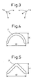
- the fuel injector 1 has a plurality of (six) round injector holes 1a arranged in an upwardly bulging arc as shown in FIG. 3 and is designed so that fuel is injected in a columnar shape from each injector hole 1a.
- the columnar shaped fuel sprays are relatively strong in penetrating force and generate strong frictional force with the intake air (tumble flow) during flight, so are atomized by the frictional force and become combined as a whole.
- the thus combined fuel spray as shown in FIG. 4 , has a cross-sectional shape vertical to the center axis in the injection direction which is an upwardly bulging curved arc shape.
- the fuel spray F having this curved shape or a cross-section of the broken line shape such as shown in FIG. 5 has a large contact area with the tumble flow, so is easily mixed with the tumble flow. Further, if making the top part of the upwardly bulging curved shape or broken line shape fuel spray pass through the spark gap 2a of the spark plug 2, since the other parts of the fuel spray are positioned below the top part, they will not strike the bottom of the cylinder head. When positioning the spark gap 2a in the flight path of the injected fuel F, it is therefore possible to make the length of the spark plug 2 projected from the bottom of the cylinder head relatively small.
- the present embodiment is designed to inject all of the injected fuel F toward the inside of the cavity 3a, preferably toward the exhaust valve side wall 3c of the cavity 3a, but serious problems such as misfires do not occur in the case of the stratified combustion method directing the fuel injected into the cavity to the spark plug direction as a combustible air-fuel mixture, so this is not that absolute. Further, as explained above, the case where it is necessary to inject all of the fuel spray F inside of the cavity 3a or toward the side wall 3c of the exhaust valve side of the cavity 3a is at the time of engine low speed operation where only a weak tumble flow is formed inside the cylinder, so it is also possible to control the fuel injection timing in accordance with the range of piston position just at this time.
- the tumble flow formed in the cylinder was made a forward tumble flow falling at the exhaust valve side and rising at the intake valve side, but it is also possible to provide a mask wall at the exhaust valve side of the part of the intake port opening into the cylinder etc. so as to form inside the cylinder a reverse tumble flow falling at the intake valve side and rising at the exhaust valve side.
- the cavity of the piston top face is biased toward the intake valve side and the inflow side of the tumble flow of the cavity becomes the intake valve side.
- the spark plug is arranged at the intake valve side near the fuel injector.
Landscapes
- Engineering & Computer Science (AREA)
- Chemical & Material Sciences (AREA)
- Combustion & Propulsion (AREA)
- Mechanical Engineering (AREA)
- General Engineering & Computer Science (AREA)
- Combustion Methods Of Internal-Combustion Engines (AREA)
- Ignition Installations For Internal Combustion Engines (AREA)
- Fuel-Injection Apparatus (AREA)
Claims (8)
- Verbrennungsmotor mit Fremdzündung und Direkteinspritzung, mit:einer Kraftstoffeinspritzeinrichtung (1) zum direkten Einspritzen von Kraftstoff in einen Zylinder,eine Zündkerze (2), welche eine Funkenstrecke in einen Flugpfad eines von der Kraftstoffeinspritzeinrichtung (1) eingespritzten Kraftstoffs platziert, undeine Ausnehmung (3a), die in einem Kolbenboden ausgebildet ist,dadurch gekennzeichnet, dassdie Kraftstoffeinspritzeinrichtung (1) bei einer geschichteten Verbrennung im Wesentlichen den gesamten Kraftstoff in eine Richtung einspritzt, so dass sich dieser mit einer Tumble-Strömung (T) entlang der Verwirbelungsrichtung der Tumble-Strömung (T) vermischt, die bei einem Verdichtungshub in eine Längsrichtung der Ausnehmung (3a) herumwirbelt, und die Zündkerze (2) den Kraftstoff (F) entzündet, der am Ende der Einspritzperiode eingespritzt wird, während dieser die Zündstrecke (2a) passiert.
- Verbrennungsmotor mit Fremdzündung und Direkteinspritzung nach Anspruch 1, dadurch gekennzeichnet, dass die Ausnehmung (3a) eine Fase oder Ausrundung (3b) auf der Einströmseite der Tumble-Strömung (T) aufweist.
- Verbrennungsmotor mit Fremdzündung und Direkteinspritzung nach Anspruch 1, dadurch gekennzeichnet, dass die Ausnehmung (3a) in dem Kolbenboden zur Auslassventilseite hin tendiert und dass die Tumble-Strömung (T) von der Auslassventilseite der Ausnehmung (3a) entlang der Innenwandung der Ausnehmung zu der Einlassventilseite herumwirbelt.
- Verbrennungsmotor mit Fremdzündung und Direkteinspritzung nach Anspruch 1, dadurch gekennzeichnet, dass die Zündkerze (2a) mit einer Masseelektrode mit einem L-förmigen Querschnitt versehen ist, der einen parallelen Abschnitt (2b), der im Wesentlichen parallel zu einer Achse des Zündkerzenkörpers ist, und einen vertikalen Abschnitt (2c), der im Wesentlichen senkrecht zu der Achse des Zündkerzenkörpers ist, aufweist und so angeordnet ist, dass der parallele Abschnitt der Masseelektrode an der stromabwärtigen Seite der Tumble-Strömung (T) nicht der Tumble-Strömung (T) zugewandt ist.
- Verbrennungsmotor mit Fremdzündung und Direkteinspritzung nach Anspruch 1, dadurch gekennzeichnet, dass die Kraftstoffeinspritzeinrichtung (1) im Wesentlichen den gesamten Kraftstoff zur Innenseite der Ausnehmung (3a) einspritzt.
- Verbrennungsmotor mit Fremdzündung und Direkteinspritzung nach Anspruch 1, dadurch gekennzeichnet, dass die Kraftstoffeinspritzeinrichtung (1) im Wesentlichen den gesamten Kraftstoff zu einer auf der Einströmseite der Tumble-Strömung (T) befindlichen Innenwand (3c) in die Ausnehmung (3a) einspritzt.
- Verbrennungsmotor mit Fremdzündung und Direkteinspritzung nach Anspruch 1, dadurch gekennzeichnet, dass der von der Kraftstoffeinspritzeinrichtung (1) eingespritzte Kraftstoff senkrecht zur Mittellinie in Einspritzrichtung eine Querschnittsform eine Form einer nach oben ausbauchenden unterbrochenen oder gekrümmten Linienform hat.
- Verbrennungsmotor mit Fremdzündung und Direkteinspritzung nach Anspruch 1, dadurch gekennzeichnet, dass das Volumen der Ausnehmung bezüglich der maximalen Kraftstoffeinspritzmenge bei einer geschichteten Verbrennung so gewählt wird, dass das Luft-Kraftstoff-Verhältnis des Luft-Kraftstoff-Gemisches, welches in der Ausnehmung ausgebildet wird, nicht fetter als ein voreingestelltes Luft-Kraftstoff-Verhältnis wird.
Applications Claiming Priority (2)
| Application Number | Priority Date | Filing Date | Title |
|---|---|---|---|
| JP2005188182A JP4342481B2 (ja) | 2005-06-28 | 2005-06-28 | 筒内噴射式火花点火内燃機関 |
| PCT/JP2006/312190 WO2007000907A1 (ja) | 2005-06-28 | 2006-06-12 | 筒内噴射式火花点火内燃機関 |
Publications (4)
| Publication Number | Publication Date |
|---|---|
| EP1898064A1 EP1898064A1 (de) | 2008-03-12 |
| EP1898064A4 EP1898064A4 (de) | 2009-06-24 |
| EP1898064B1 true EP1898064B1 (de) | 2012-10-24 |
| EP1898064B8 EP1898064B8 (de) | 2012-12-05 |
Family
ID=37595161
Family Applications (1)
| Application Number | Title | Priority Date | Filing Date |
|---|---|---|---|
| EP06747318A Not-in-force EP1898064B8 (de) | 2005-06-28 | 2006-06-12 | Verbrennungsmotor mit fremdzündung und direkteinspritzung |
Country Status (7)
| Country | Link |
|---|---|
| US (1) | US7926463B2 (de) |
| EP (1) | EP1898064B8 (de) |
| JP (1) | JP4342481B2 (de) |
| KR (1) | KR100926660B1 (de) |
| CN (1) | CN100513754C (de) |
| ES (1) | ES2398094T3 (de) |
| WO (1) | WO2007000907A1 (de) |
Families Citing this family (19)
| Publication number | Priority date | Publication date | Assignee | Title |
|---|---|---|---|---|
| US7048155B2 (en) * | 2001-11-30 | 2006-05-23 | Yoshino Kogyosho Co., Ltd. | Depression head for pump mechanism |
| JP2007297989A (ja) * | 2006-05-01 | 2007-11-15 | Toyota Motor Corp | 筒内噴射式火花点火内燃機関 |
| JP4306711B2 (ja) * | 2006-09-29 | 2009-08-05 | トヨタ自動車株式会社 | 筒内噴射式火花点火内燃機関 |
| JP4984976B2 (ja) * | 2007-03-06 | 2012-07-25 | トヨタ自動車株式会社 | 筒内噴射式火花点火内燃機関の制御装置 |
| JP4840242B2 (ja) * | 2007-04-23 | 2011-12-21 | トヨタ自動車株式会社 | 筒内噴射式火花点火内燃機関 |
| JP4985077B2 (ja) * | 2007-04-23 | 2012-07-25 | トヨタ自動車株式会社 | 筒内噴射式火花点火内燃機関 |
| JP5104195B2 (ja) * | 2007-10-19 | 2012-12-19 | トヨタ自動車株式会社 | 火花点火内燃機関 |
| US20110231316A1 (en) * | 2010-03-09 | 2011-09-22 | Cummins Intellectual Properties, Inc. | Method, system and computer readable media containing a program for identifying whether a product is genuine |
| CN105719149B (zh) | 2010-03-09 | 2019-12-10 | 康明斯过滤Ip公司 | 用于检测原装可维护产品部件的存在性的装置、系统和方法 |
| US8833327B2 (en) | 2011-12-28 | 2014-09-16 | Cummins Intellectual Property, Inc. | Piston and combustion chamber |
| FR2986564B1 (fr) * | 2012-02-06 | 2014-02-28 | Vianney Rabhi | Dispositif d'allumage par etincelle et stratification haute-pression pour moteur a combustion interne |
| WO2014188598A1 (ja) * | 2013-05-24 | 2014-11-27 | トヨタ自動車株式会社 | 内燃機関の燃料噴射弁 |
| JP6206158B2 (ja) | 2013-12-17 | 2017-10-04 | トヨタ自動車株式会社 | 火花点火式内燃機関の制御システム |
| JP6088016B1 (ja) * | 2015-09-18 | 2017-03-01 | 富士重工業株式会社 | ピストン |
| JP6337877B2 (ja) * | 2015-12-10 | 2018-06-06 | マツダ株式会社 | 内燃機関の燃焼室構造 |
| JP6825553B2 (ja) * | 2017-12-28 | 2021-02-03 | トヨタ自動車株式会社 | 内燃機関の制御装置 |
| EP3779154A4 (de) * | 2018-04-10 | 2021-04-14 | Nissan Motor Co., Ltd. | Brennkraftmaschinensteuerungsverfahren und brennkraftmaschine |
| JP2020007977A (ja) * | 2018-07-09 | 2020-01-16 | トヨタ自動車株式会社 | 圧縮自着火式内燃機関 |
| JP7589595B2 (ja) * | 2021-03-08 | 2024-11-26 | マツダ株式会社 | エンジンの燃焼室構造 |
Family Cites Families (23)
| Publication number | Priority date | Publication date | Assignee | Title |
|---|---|---|---|---|
| US3318292A (en) * | 1964-12-10 | 1967-05-09 | Ford Motor Co | Internal combustion engine |
| JP3681080B2 (ja) | 1996-02-09 | 2005-08-10 | 富士重工業株式会社 | 筒内直噴式火花点火エンジンの燃焼室構造 |
| US5960767A (en) * | 1996-02-09 | 1999-10-05 | Fuji Jukogyo Kabushiki Kaisha | Combustion chamber of in-cylinder direct fuel injection engine |
| JP3233039B2 (ja) * | 1996-08-28 | 2001-11-26 | 三菱自動車工業株式会社 | 筒内噴射型火花点火式内燃エンジンの制御装置 |
| JP3741494B2 (ja) * | 1996-10-31 | 2006-02-01 | 富士重工業株式会社 | 筒内噴射式エンジン |
| JPH10299537A (ja) * | 1997-04-28 | 1998-11-10 | Mazda Motor Corp | 筒内噴射型火花点火式エンジン |
| JP3781536B2 (ja) | 1997-12-17 | 2006-05-31 | 富士重工業株式会社 | 筒内噴射式エンジンの燃焼室構造 |
| JP3733721B2 (ja) * | 1997-12-18 | 2006-01-11 | 日産自動車株式会社 | 直噴火花点火式内燃機関 |
| JP3644228B2 (ja) * | 1998-01-07 | 2005-04-27 | 日産自動車株式会社 | 筒内噴射式火花点火機関 |
| KR20010074482A (ko) * | 1998-04-10 | 2001-08-04 | 추후제출 | 점화 제어 방식의 직접 분사형 내연 기관 |
| JP3644249B2 (ja) * | 1998-04-22 | 2005-04-27 | 日産自動車株式会社 | 筒内噴射式内燃機関 |
| JP3903657B2 (ja) * | 1998-12-02 | 2007-04-11 | トヨタ自動車株式会社 | 筒内噴射式火花点火内燃機関 |
| JP3671785B2 (ja) * | 1999-12-15 | 2005-07-13 | 株式会社日立製作所 | 筒内噴射型内燃機関の燃料噴射装置 |
| JP2001241329A (ja) * | 2000-02-28 | 2001-09-07 | Hitachi Ltd | 筒内噴射型内燃機関 |
| JP4415497B2 (ja) * | 2000-03-29 | 2010-02-17 | マツダ株式会社 | 火花点火式直噴エンジン |
| JP3926989B2 (ja) * | 2001-02-01 | 2007-06-06 | 株式会社日立製作所 | 筒内噴射式火花点火エンジンの制御装置 |
| JP2004245204A (ja) * | 2003-02-17 | 2004-09-02 | Mitsubishi Motors Corp | 内燃機関の燃料噴射装置 |
| JP2004316568A (ja) * | 2003-04-17 | 2004-11-11 | Nissan Motor Co Ltd | 筒内直接噴射式内燃機関 |
| JP2004353594A (ja) * | 2003-05-30 | 2004-12-16 | Nissan Motor Co Ltd | 筒内直接噴射式内燃機関 |
| JP4161796B2 (ja) | 2003-05-16 | 2008-10-08 | 株式会社日立製作所 | 筒内噴射式火花点火機関の暖機制御方法 |
| JP4143843B2 (ja) * | 2003-09-29 | 2008-09-03 | 三菱自動車工業株式会社 | 筒内噴射型火花点火式内燃機関 |
| DE10354827A1 (de) * | 2003-11-24 | 2005-06-23 | Robert Bosch Gmbh | Brennstoffeinspritzsystem |
| JP2005264768A (ja) * | 2004-03-17 | 2005-09-29 | Nissan Motor Co Ltd | 内燃機関 |
-
2005
- 2005-06-28 JP JP2005188182A patent/JP4342481B2/ja not_active Expired - Fee Related
-
2006
- 2006-06-12 CN CNB2006800115865A patent/CN100513754C/zh not_active Expired - Fee Related
- 2006-06-12 WO PCT/JP2006/312190 patent/WO2007000907A1/ja not_active Ceased
- 2006-06-12 US US11/915,640 patent/US7926463B2/en not_active Expired - Fee Related
- 2006-06-12 KR KR1020077017356A patent/KR100926660B1/ko not_active Expired - Fee Related
- 2006-06-12 ES ES06747318T patent/ES2398094T3/es active Active
- 2006-06-12 EP EP06747318A patent/EP1898064B8/de not_active Not-in-force
Also Published As
| Publication number | Publication date |
|---|---|
| CN100513754C (zh) | 2009-07-15 |
| US20090194066A1 (en) | 2009-08-06 |
| EP1898064B8 (de) | 2012-12-05 |
| ES2398094T3 (es) | 2013-03-13 |
| KR100926660B1 (ko) | 2009-11-17 |
| EP1898064A1 (de) | 2008-03-12 |
| US7926463B2 (en) | 2011-04-19 |
| WO2007000907A1 (ja) | 2007-01-04 |
| KR20070095370A (ko) | 2007-09-28 |
| JP4342481B2 (ja) | 2009-10-14 |
| JP2007009722A (ja) | 2007-01-18 |
| EP1898064A4 (de) | 2009-06-24 |
| CN101155982A (zh) | 2008-04-02 |
Similar Documents
| Publication | Publication Date | Title |
|---|---|---|
| EP1898064B1 (de) | Verbrennungsmotor mit fremdzündung und direkteinspritzung | |
| JP4501950B2 (ja) | 内燃機関の燃焼制御装置 | |
| EP1179662A2 (de) | Ottomotor mit Direkteinspritzung | |
| US7597085B2 (en) | Direct fuel injection-type spark ignition internal combustion engine | |
| US6935302B2 (en) | In-cylinder injection type internal combustion engine | |
| KR100941193B1 (ko) | 통내 분사형 불꽃 점화식 내연기관 | |
| CN109973202A (zh) | 内燃机的控制装置 | |
| JP2009019502A (ja) | 筒内噴射型火花点火式内燃機関 | |
| JP3627546B2 (ja) | 直接筒内噴射式火花点火機関 | |
| JP2009121251A (ja) | 筒内噴射式火花点火内燃機関 | |
| CN100543287C (zh) | 缸内喷射式火花点火内燃机 | |
| JP2007138780A (ja) | 副室式内燃機関 | |
| JP4582049B2 (ja) | 筒内噴射式火花点火内燃機関 | |
| JP4428273B2 (ja) | 筒内直接噴射式内燃機関 | |
| JP7740516B2 (ja) | エンジン | |
| JP2007285205A (ja) | 筒内噴射式火花点火内燃機関 | |
| JP2005155395A (ja) | 筒内直接噴射式内燃機関 | |
| WO2024201932A1 (ja) | 副燃焼室付内燃機関 | |
| JPH0248673Y2 (de) | ||
| JP2000303844A (ja) | 筒内噴射式火花点火内燃機関 | |
| JP2009074498A (ja) | 燃料噴射弁 | |
| JP2006200494A (ja) | 筒内噴射式火花点火内燃機関 | |
| JP2007285198A (ja) | 火花点火内燃機関 | |
| KR20040028368A (ko) | 가솔린 직접분사용 다공 스월 인젝터 |
Legal Events
| Date | Code | Title | Description |
|---|---|---|---|
| PUAI | Public reference made under article 153(3) epc to a published international application that has entered the european phase |
Free format text: ORIGINAL CODE: 0009012 |
|
| 17P | Request for examination filed |
Effective date: 20071127 |
|
| AK | Designated contracting states |
Kind code of ref document: A1 Designated state(s): DE ES FR GB IT |
|
| DAX | Request for extension of the european patent (deleted) | ||
| RBV | Designated contracting states (corrected) |
Designated state(s): DE ES FR GB IT |
|
| DAX | Request for extension of the european patent (deleted) | ||
| A4 | Supplementary search report drawn up and despatched |
Effective date: 20090526 |
|
| GRAP | Despatch of communication of intention to grant a patent |
Free format text: ORIGINAL CODE: EPIDOSNIGR1 |
|
| GRAS | Grant fee paid |
Free format text: ORIGINAL CODE: EPIDOSNIGR3 |
|
| GRAA | (expected) grant |
Free format text: ORIGINAL CODE: 0009210 |
|
| RIN1 | Information on inventor provided before grant (corrected) |
Inventor name: MATSUMOTO, KEISUKE Inventor name: ASHIZAWA, TAKESHI Inventor name: TOMINO, OSAMU Inventor name: NOMURA, HIROSHI Inventor name: MAEDA, KAORU Inventor name: KUSHIDA, TAKEO |
|
| AK | Designated contracting states |
Kind code of ref document: B1 Designated state(s): DE ES FR GB IT |
|
| REG | Reference to a national code |
Ref country code: GB Ref legal event code: FG4D |
|
| RIN2 | Information on inventor provided after grant (corrected) |
Inventor name: ASHIZAWA, TAKESHI Inventor name: TOMINO, OSAMU Inventor name: KUSHIDA, TAKEO Inventor name: MAEDA, KAORU Inventor name: NOMURA, HIROSHI Inventor name: MATSUMOTO, KEISUKE |
|
| REG | Reference to a national code |
Ref country code: DE Ref legal event code: R096 Ref document number: 602006032655 Country of ref document: DE Effective date: 20121227 |
|
| RAP2 | Party data changed (patent owner data changed or rights of a patent transferred) |
Owner name: BOSCH CORPORATION Owner name: TOYOTA JIDOSHA KABUSHIKI KAISHA |
|
| REG | Reference to a national code |
Ref country code: ES Ref legal event code: FG2A Ref document number: 2398094 Country of ref document: ES Kind code of ref document: T3 Effective date: 20130313 |
|
| PLBE | No opposition filed within time limit |
Free format text: ORIGINAL CODE: 0009261 |
|
| STAA | Information on the status of an ep patent application or granted ep patent |
Free format text: STATUS: NO OPPOSITION FILED WITHIN TIME LIMIT |
|
| 26N | No opposition filed |
Effective date: 20130725 |
|
| REG | Reference to a national code |
Ref country code: DE Ref legal event code: R097 Ref document number: 602006032655 Country of ref document: DE Effective date: 20130725 |
|
| REG | Reference to a national code |
Ref country code: DE Ref legal event code: R084 Ref document number: 602006032655 Country of ref document: DE |
|
| REG | Reference to a national code |
Ref country code: GB Ref legal event code: 746 Effective date: 20160316 |
|
| REG | Reference to a national code |
Ref country code: FR Ref legal event code: PLFP Year of fee payment: 11 |
|
| REG | Reference to a national code |
Ref country code: FR Ref legal event code: PLFP Year of fee payment: 12 |
|
| REG | Reference to a national code |
Ref country code: FR Ref legal event code: PLFP Year of fee payment: 13 |
|
| PGFP | Annual fee paid to national office [announced via postgrant information from national office to epo] |
Ref country code: FR Payment date: 20210513 Year of fee payment: 16 Ref country code: DE Payment date: 20210518 Year of fee payment: 16 Ref country code: IT Payment date: 20210511 Year of fee payment: 16 |
|
| PGFP | Annual fee paid to national office [announced via postgrant information from national office to epo] |
Ref country code: GB Payment date: 20210519 Year of fee payment: 16 |
|
| PGFP | Annual fee paid to national office [announced via postgrant information from national office to epo] |
Ref country code: ES Payment date: 20210705 Year of fee payment: 16 |
|
| REG | Reference to a national code |
Ref country code: DE Ref legal event code: R119 Ref document number: 602006032655 Country of ref document: DE |
|
| GBPC | Gb: european patent ceased through non-payment of renewal fee |
Effective date: 20220612 |
|
| PG25 | Lapsed in a contracting state [announced via postgrant information from national office to epo] |
Ref country code: FR Free format text: LAPSE BECAUSE OF NON-PAYMENT OF DUE FEES Effective date: 20220630 |
|
| PG25 | Lapsed in a contracting state [announced via postgrant information from national office to epo] |
Ref country code: GB Free format text: LAPSE BECAUSE OF NON-PAYMENT OF DUE FEES Effective date: 20220612 Ref country code: DE Free format text: LAPSE BECAUSE OF NON-PAYMENT OF DUE FEES Effective date: 20230103 |
|
| REG | Reference to a national code |
Ref country code: ES Ref legal event code: FD2A Effective date: 20230728 |
|
| PG25 | Lapsed in a contracting state [announced via postgrant information from national office to epo] |
Ref country code: IT Free format text: LAPSE BECAUSE OF NON-PAYMENT OF DUE FEES Effective date: 20220612 |
|
| PG25 | Lapsed in a contracting state [announced via postgrant information from national office to epo] |
Ref country code: ES Free format text: LAPSE BECAUSE OF NON-PAYMENT OF DUE FEES Effective date: 20220613 |