EP1898265A2 - Appareil pour la fabrication d'un précurseur de toner, son procédé, précurseur de toner fibreux, appareil pour la fabrication de toner et procédé pour la fabrication de toner électrophotographique et fines particules de résine - Google Patents
Appareil pour la fabrication d'un précurseur de toner, son procédé, précurseur de toner fibreux, appareil pour la fabrication de toner et procédé pour la fabrication de toner électrophotographique et fines particules de résine Download PDFInfo
- Publication number
- EP1898265A2 EP1898265A2 EP07116036A EP07116036A EP1898265A2 EP 1898265 A2 EP1898265 A2 EP 1898265A2 EP 07116036 A EP07116036 A EP 07116036A EP 07116036 A EP07116036 A EP 07116036A EP 1898265 A2 EP1898265 A2 EP 1898265A2
- Authority
- EP
- European Patent Office
- Prior art keywords
- nozzle
- toner
- producing
- fibrous
- precursor
- Prior art date
- Legal status (The legal status is an assumption and is not a legal conclusion. Google has not performed a legal analysis and makes no representation as to the accuracy of the status listed.)
- Granted
Links
- 229920005989 resin Polymers 0.000 title claims abstract description 139
- 239000011347 resin Substances 0.000 title claims abstract description 139
- 239000002243 precursor Substances 0.000 title claims abstract description 100
- 238000000034 method Methods 0.000 title claims abstract description 51
- 239000002245 particle Substances 0.000 title claims description 110
- 238000004519 manufacturing process Methods 0.000 title claims description 41
- 239000002994 raw material Substances 0.000 claims abstract description 91
- 238000010298 pulverizing process Methods 0.000 claims abstract description 44
- 239000000463 material Substances 0.000 claims abstract description 30
- 239000012530 fluid Substances 0.000 claims abstract description 19
- 239000000049 pigment Substances 0.000 claims abstract description 13
- 238000002844 melting Methods 0.000 claims abstract description 11
- 230000008018 melting Effects 0.000 claims abstract description 11
- 239000000470 constituent Substances 0.000 claims abstract description 8
- 239000003960 organic solvent Substances 0.000 claims abstract description 5
- 239000002415 cerumenolytic agent Substances 0.000 claims abstract description 4
- 239000000835 fiber Substances 0.000 claims description 147
- 238000009826 distribution Methods 0.000 claims description 57
- 238000002156 mixing Methods 0.000 claims description 37
- 239000010419 fine particle Substances 0.000 claims description 35
- 239000000203 mixture Substances 0.000 claims description 16
- 230000008569 process Effects 0.000 claims description 12
- 238000004898 kneading Methods 0.000 claims description 11
- 239000000126 substance Substances 0.000 claims description 11
- 238000005520 cutting process Methods 0.000 abstract description 8
- 238000012545 processing Methods 0.000 abstract description 6
- 239000007789 gas Substances 0.000 description 131
- 230000000052 comparative effect Effects 0.000 description 47
- 229920001577 copolymer Polymers 0.000 description 26
- 238000009987 spinning Methods 0.000 description 23
- 230000006872 improvement Effects 0.000 description 22
- 230000010349 pulsation Effects 0.000 description 19
- CURLTUGMZLYLDI-UHFFFAOYSA-N Carbon dioxide Chemical compound O=C=O CURLTUGMZLYLDI-UHFFFAOYSA-N 0.000 description 18
- 230000001276 controlling effect Effects 0.000 description 18
- 230000003068 static effect Effects 0.000 description 18
- 230000003247 decreasing effect Effects 0.000 description 16
- 238000001125 extrusion Methods 0.000 description 15
- 230000000694 effects Effects 0.000 description 14
- 238000011156 evaluation Methods 0.000 description 13
- 230000002829 reductive effect Effects 0.000 description 13
- 239000001993 wax Substances 0.000 description 13
- IJGRMHOSHXDMSA-UHFFFAOYSA-N Atomic nitrogen Chemical compound N#N IJGRMHOSHXDMSA-UHFFFAOYSA-N 0.000 description 12
- 230000007246 mechanism Effects 0.000 description 12
- 229910002092 carbon dioxide Inorganic materials 0.000 description 11
- 238000010438 heat treatment Methods 0.000 description 10
- 229920001225 polyester resin Polymers 0.000 description 10
- 239000004645 polyester resin Substances 0.000 description 10
- 239000003795 chemical substances by application Substances 0.000 description 9
- 239000000843 powder Substances 0.000 description 9
- PPBRXRYQALVLMV-UHFFFAOYSA-N Styrene Chemical compound C=CC1=CC=CC=C1 PPBRXRYQALVLMV-UHFFFAOYSA-N 0.000 description 8
- 239000001569 carbon dioxide Substances 0.000 description 7
- -1 bordeaux 10B Chemical compound 0.000 description 6
- 239000000428 dust Substances 0.000 description 6
- 229910052757 nitrogen Inorganic materials 0.000 description 5
- 230000000704 physical effect Effects 0.000 description 5
- RTZKZFJDLAIYFH-UHFFFAOYSA-N Diethyl ether Chemical compound CCOCC RTZKZFJDLAIYFH-UHFFFAOYSA-N 0.000 description 4
- 241000209094 Oryza Species 0.000 description 4
- 235000007164 Oryza sativa Nutrition 0.000 description 4
- 239000004203 carnauba wax Substances 0.000 description 4
- 235000013869 carnauba wax Nutrition 0.000 description 4
- 239000004359 castor oil Substances 0.000 description 4
- 235000019438 castor oil Nutrition 0.000 description 4
- 230000015556 catabolic process Effects 0.000 description 4
- 230000008859 change Effects 0.000 description 4
- 230000007423 decrease Effects 0.000 description 4
- 238000006731 degradation reaction Methods 0.000 description 4
- ZEMPKEQAKRGZGQ-XOQCFJPHSA-N glycerol triricinoleate Natural products CCCCCC[C@@H](O)CC=CCCCCCCCC(=O)OC[C@@H](COC(=O)CCCCCCCC=CC[C@@H](O)CCCCCC)OC(=O)CCCCCCCC=CC[C@H](O)CCCCCC ZEMPKEQAKRGZGQ-XOQCFJPHSA-N 0.000 description 4
- 238000005259 measurement Methods 0.000 description 4
- 238000002074 melt spinning Methods 0.000 description 4
- 235000019271 petrolatum Nutrition 0.000 description 4
- 239000005011 phenolic resin Substances 0.000 description 4
- 229920000642 polymer Polymers 0.000 description 4
- 238000007639 printing Methods 0.000 description 4
- 235000009566 rice Nutrition 0.000 description 4
- 238000011144 upstream manufacturing Methods 0.000 description 4
- ZWEHNKRNPOVVGH-UHFFFAOYSA-N 2-Butanone Chemical compound CCC(C)=O ZWEHNKRNPOVVGH-UHFFFAOYSA-N 0.000 description 3
- QTBSBXVTEAMEQO-UHFFFAOYSA-N Acetic acid Chemical compound CC(O)=O QTBSBXVTEAMEQO-UHFFFAOYSA-N 0.000 description 3
- CSCPPACGZOOCGX-UHFFFAOYSA-N Acetone Chemical compound CC(C)=O CSCPPACGZOOCGX-UHFFFAOYSA-N 0.000 description 3
- UHOVQNZJYSORNB-UHFFFAOYSA-N Benzene Chemical compound C1=CC=CC=C1 UHOVQNZJYSORNB-UHFFFAOYSA-N 0.000 description 3
- ZMXDDKWLCZADIW-UHFFFAOYSA-N N,N-Dimethylformamide Chemical compound CN(C)C=O ZMXDDKWLCZADIW-UHFFFAOYSA-N 0.000 description 3
- CTQNGGLPUBDAKN-UHFFFAOYSA-N O-Xylene Chemical compound CC1=CC=CC=C1C CTQNGGLPUBDAKN-UHFFFAOYSA-N 0.000 description 3
- YXFVVABEGXRONW-UHFFFAOYSA-N Toluene Chemical compound CC1=CC=CC=C1 YXFVVABEGXRONW-UHFFFAOYSA-N 0.000 description 3
- 238000009825 accumulation Methods 0.000 description 3
- 229910052782 aluminium Inorganic materials 0.000 description 3
- XAGFODPZIPBFFR-UHFFFAOYSA-N aluminium Chemical compound [Al] XAGFODPZIPBFFR-UHFFFAOYSA-N 0.000 description 3
- 230000008901 benefit Effects 0.000 description 3
- 239000001273 butane Substances 0.000 description 3
- 230000000875 corresponding effect Effects 0.000 description 3
- 239000003822 epoxy resin Substances 0.000 description 3
- 150000002148 esters Chemical class 0.000 description 3
- 230000005484 gravity Effects 0.000 description 3
- 229930195733 hydrocarbon Natural products 0.000 description 3
- 150000002430 hydrocarbons Chemical class 0.000 description 3
- 150000002576 ketones Chemical class 0.000 description 3
- VLKZOEOYAKHREP-UHFFFAOYSA-N n-Hexane Chemical compound CCCCCC VLKZOEOYAKHREP-UHFFFAOYSA-N 0.000 description 3
- IJDNQMDRQITEOD-UHFFFAOYSA-N n-butane Chemical compound CCCC IJDNQMDRQITEOD-UHFFFAOYSA-N 0.000 description 3
- OFBQJSOFQDEBGM-UHFFFAOYSA-N n-pentane Natural products CCCCC OFBQJSOFQDEBGM-UHFFFAOYSA-N 0.000 description 3
- 230000003287 optical effect Effects 0.000 description 3
- 239000003208 petroleum Substances 0.000 description 3
- 229920000647 polyepoxide Polymers 0.000 description 3
- 230000009467 reduction Effects 0.000 description 3
- 238000000926 separation method Methods 0.000 description 3
- 230000000007 visual effect Effects 0.000 description 3
- 239000008096 xylene Substances 0.000 description 3
- KPAPHODVWOVUJL-UHFFFAOYSA-N 1-benzofuran;1h-indene Chemical compound C1=CC=C2CC=CC2=C1.C1=CC=C2OC=CC2=C1 KPAPHODVWOVUJL-UHFFFAOYSA-N 0.000 description 2
- 239000004925 Acrylic resin Substances 0.000 description 2
- 229920000178 Acrylic resin Polymers 0.000 description 2
- XKRFYHLGVUSROY-UHFFFAOYSA-N Argon Chemical compound [Ar] XKRFYHLGVUSROY-UHFFFAOYSA-N 0.000 description 2
- VTYYLEPIZMXCLO-UHFFFAOYSA-L Calcium carbonate Chemical compound [Ca+2].[O-]C([O-])=O VTYYLEPIZMXCLO-UHFFFAOYSA-L 0.000 description 2
- XDTMQSROBMDMFD-UHFFFAOYSA-N Cyclohexane Chemical compound C1CCCCC1 XDTMQSROBMDMFD-UHFFFAOYSA-N 0.000 description 2
- ROSDSFDQCJNGOL-UHFFFAOYSA-N Dimethylamine Chemical compound CNC ROSDSFDQCJNGOL-UHFFFAOYSA-N 0.000 description 2
- IAZDPXIOMUYVGZ-UHFFFAOYSA-N Dimethylsulphoxide Chemical compound CS(C)=O IAZDPXIOMUYVGZ-UHFFFAOYSA-N 0.000 description 2
- LFQSCWFLJHTTHZ-UHFFFAOYSA-N Ethanol Chemical compound CCO LFQSCWFLJHTTHZ-UHFFFAOYSA-N 0.000 description 2
- UQSXHKLRYXJYBZ-UHFFFAOYSA-N Iron oxide Chemical compound [Fe]=O UQSXHKLRYXJYBZ-UHFFFAOYSA-N 0.000 description 2
- 239000004264 Petrolatum Substances 0.000 description 2
- 239000004698 Polyethylene Substances 0.000 description 2
- 239000004743 Polypropylene Substances 0.000 description 2
- 239000004793 Polystyrene Substances 0.000 description 2
- OFOBLEOULBTSOW-UHFFFAOYSA-N Propanedioic acid Natural products OC(=O)CC(O)=O OFOBLEOULBTSOW-UHFFFAOYSA-N 0.000 description 2
- JUJWROOIHBZHMG-UHFFFAOYSA-N Pyridine Chemical compound C1=CC=NC=C1 JUJWROOIHBZHMG-UHFFFAOYSA-N 0.000 description 2
- NRCMAYZCPIVABH-UHFFFAOYSA-N Quinacridone Chemical compound N1C2=CC=CC=C2C(=O)C2=C1C=C1C(=O)C3=CC=CC=C3NC1=C2 NRCMAYZCPIVABH-UHFFFAOYSA-N 0.000 description 2
- WYURNTSHIVDZCO-UHFFFAOYSA-N Tetrahydrofuran Chemical compound C1CCOC1 WYURNTSHIVDZCO-UHFFFAOYSA-N 0.000 description 2
- 150000001241 acetals Chemical class 0.000 description 2
- 230000002776 aggregation Effects 0.000 description 2
- 238000004220 aggregation Methods 0.000 description 2
- RGCKGOZRHPZPFP-UHFFFAOYSA-N alizarin Chemical compound C1=CC=C2C(=O)C3=C(O)C(O)=CC=C3C(=O)C2=C1 RGCKGOZRHPZPFP-UHFFFAOYSA-N 0.000 description 2
- 150000001408 amides Chemical class 0.000 description 2
- TZCXTZWJZNENPQ-UHFFFAOYSA-L barium sulfate Chemical compound [Ba+2].[O-]S([O-])(=O)=O TZCXTZWJZNENPQ-UHFFFAOYSA-L 0.000 description 2
- 239000011230 binding agent Substances 0.000 description 2
- 230000015572 biosynthetic process Effects 0.000 description 2
- 238000007664 blowing Methods 0.000 description 2
- NMJJFJNHVMGPGM-UHFFFAOYSA-N butyl formate Chemical compound CCCCOC=O NMJJFJNHVMGPGM-UHFFFAOYSA-N 0.000 description 2
- 239000004204 candelilla wax Substances 0.000 description 2
- 235000013868 candelilla wax Nutrition 0.000 description 2
- 229940073532 candelilla wax Drugs 0.000 description 2
- 239000012185 ceresin wax Substances 0.000 description 2
- 239000011248 coating agent Substances 0.000 description 2
- 238000000576 coating method Methods 0.000 description 2
- 238000007796 conventional method Methods 0.000 description 2
- 230000008021 deposition Effects 0.000 description 2
- 235000014113 dietary fatty acids Nutrition 0.000 description 2
- XBDQKXXYIPTUBI-UHFFFAOYSA-N dimethylselenoniopropionate Natural products CCC(O)=O XBDQKXXYIPTUBI-UHFFFAOYSA-N 0.000 description 2
- 239000006185 dispersion Substances 0.000 description 2
- 238000005265 energy consumption Methods 0.000 description 2
- 238000005516 engineering process Methods 0.000 description 2
- FKRCODPIKNYEAC-UHFFFAOYSA-N ethyl propionate Chemical compound CCOC(=O)CC FKRCODPIKNYEAC-UHFFFAOYSA-N 0.000 description 2
- 239000000194 fatty acid Substances 0.000 description 2
- 229930195729 fatty acid Natural products 0.000 description 2
- 239000000542 fatty acid esters of ascorbic acid Substances 0.000 description 2
- 150000004665 fatty acids Chemical class 0.000 description 2
- 238000009472 formulation Methods 0.000 description 2
- 239000007849 furan resin Substances 0.000 description 2
- IUJAMGNYPWYUPM-UHFFFAOYSA-N hentriacontane Chemical compound CCCCCCCCCCCCCCCCCCCCCCCCCCCCCCC IUJAMGNYPWYUPM-UHFFFAOYSA-N 0.000 description 2
- 150000003949 imides Chemical class 0.000 description 2
- 239000000696 magnetic material Substances 0.000 description 2
- 230000014759 maintenance of location Effects 0.000 description 2
- VZCYOOQTPOCHFL-UPHRSURJSA-N maleic acid Chemical compound OC(=O)\C=C/C(O)=O VZCYOOQTPOCHFL-UPHRSURJSA-N 0.000 description 2
- 239000011976 maleic acid Substances 0.000 description 2
- 229910052751 metal Inorganic materials 0.000 description 2
- 239000002184 metal Substances 0.000 description 2
- BDAGIHXWWSANSR-UHFFFAOYSA-N methanoic acid Natural products OC=O BDAGIHXWWSANSR-UHFFFAOYSA-N 0.000 description 2
- 239000012184 mineral wax Substances 0.000 description 2
- 230000004048 modification Effects 0.000 description 2
- 238000012986 modification Methods 0.000 description 2
- 239000012170 montan wax Substances 0.000 description 2
- LQNUZADURLCDLV-UHFFFAOYSA-N nitrobenzene Chemical compound [O-][N+](=O)C1=CC=CC=C1 LQNUZADURLCDLV-UHFFFAOYSA-N 0.000 description 2
- 239000004745 nonwoven fabric Substances 0.000 description 2
- 210000000056 organ Anatomy 0.000 description 2
- 239000012188 paraffin wax Substances 0.000 description 2
- 235000019809 paraffin wax Nutrition 0.000 description 2
- 229940066842 petrolatum Drugs 0.000 description 2
- 239000012169 petroleum derived wax Substances 0.000 description 2
- 235000019381 petroleum wax Nutrition 0.000 description 2
- 239000012165 plant wax Substances 0.000 description 2
- 229920002285 poly(styrene-co-acrylonitrile) Polymers 0.000 description 2
- 229920002037 poly(vinyl butyral) polymer Polymers 0.000 description 2
- 229920006122 polyamide resin Polymers 0.000 description 2
- 229920000573 polyethylene Polymers 0.000 description 2
- 229920001155 polypropylene Polymers 0.000 description 2
- 229920002223 polystyrene Polymers 0.000 description 2
- 229920002635 polyurethane Polymers 0.000 description 2
- 239000004814 polyurethane Substances 0.000 description 2
- 229920002689 polyvinyl acetate Polymers 0.000 description 2
- 229920000915 polyvinyl chloride Polymers 0.000 description 2
- 239000004800 polyvinyl chloride Substances 0.000 description 2
- 229920002102 polyvinyl toluene Polymers 0.000 description 2
- 239000000047 product Substances 0.000 description 2
- 230000000241 respiratory effect Effects 0.000 description 2
- 238000005070 sampling Methods 0.000 description 2
- 238000005204 segregation Methods 0.000 description 2
- 229920002050 silicone resin Polymers 0.000 description 2
- 239000000344 soap Substances 0.000 description 2
- 239000002904 solvent Substances 0.000 description 2
- UBXAKNTVXQMEAG-UHFFFAOYSA-L strontium sulfate Chemical compound [Sr+2].[O-]S([O-])(=O)=O UBXAKNTVXQMEAG-UHFFFAOYSA-L 0.000 description 2
- 229920003048 styrene butadiene rubber Polymers 0.000 description 2
- 150000003440 styrenes Chemical class 0.000 description 2
- 150000003505 terpenes Chemical class 0.000 description 2
- 235000007586 terpenes Nutrition 0.000 description 2
- VZCYOOQTPOCHFL-UHFFFAOYSA-N trans-butenedioic acid Natural products OC(=O)C=CC(O)=O VZCYOOQTPOCHFL-UHFFFAOYSA-N 0.000 description 2
- QBZIEGUIYWGBMY-FUZXWUMZSA-N (5Z)-5-hydroxyimino-6-oxonaphthalene-2-sulfonic acid iron Chemical compound [Fe].O\N=C1/C(=O)C=Cc2cc(ccc12)S(O)(=O)=O.O\N=C1/C(=O)C=Cc2cc(ccc12)S(O)(=O)=O.O\N=C1/C(=O)C=Cc2cc(ccc12)S(O)(=O)=O QBZIEGUIYWGBMY-FUZXWUMZSA-N 0.000 description 1
- BGJSXRVXTHVRSN-UHFFFAOYSA-N 1,3,5-trioxane Chemical compound C1OCOCO1 BGJSXRVXTHVRSN-UHFFFAOYSA-N 0.000 description 1
- RIHXMHKNTLBIPJ-UHFFFAOYSA-N 1-nitroprop-1-ene Chemical compound CC=C[N+]([O-])=O RIHXMHKNTLBIPJ-UHFFFAOYSA-N 0.000 description 1
- HZAXFHJVJLSVMW-UHFFFAOYSA-N 2-Aminoethan-1-ol Chemical compound NCCO HZAXFHJVJLSVMW-UHFFFAOYSA-N 0.000 description 1
- FWLHAQYOFMQTHQ-UHFFFAOYSA-N 2-N-[8-[[8-(4-aminoanilino)-10-phenylphenazin-10-ium-2-yl]amino]-10-phenylphenazin-10-ium-2-yl]-8-N,10-diphenylphenazin-10-ium-2,8-diamine hydroxy-oxido-dioxochromium Chemical compound O[Cr]([O-])(=O)=O.O[Cr]([O-])(=O)=O.O[Cr]([O-])(=O)=O.Nc1ccc(Nc2ccc3nc4ccc(Nc5ccc6nc7ccc(Nc8ccc9nc%10ccc(Nc%11ccccc%11)cc%10[n+](-c%10ccccc%10)c9c8)cc7[n+](-c7ccccc7)c6c5)cc4[n+](-c4ccccc4)c3c2)cc1 FWLHAQYOFMQTHQ-UHFFFAOYSA-N 0.000 description 1
- MFYSUUPKMDJYPF-UHFFFAOYSA-N 2-[(4-methyl-2-nitrophenyl)diazenyl]-3-oxo-n-phenylbutanamide Chemical compound C=1C=CC=CC=1NC(=O)C(C(=O)C)N=NC1=CC=C(C)C=C1[N+]([O-])=O MFYSUUPKMDJYPF-UHFFFAOYSA-N 0.000 description 1
- SVONRAPFKPVNKG-UHFFFAOYSA-N 2-ethoxyethyl acetate Chemical compound CCOCCOC(C)=O SVONRAPFKPVNKG-UHFFFAOYSA-N 0.000 description 1
- WZSFTHVIIGGDOI-UHFFFAOYSA-N 4,5,6,7-tetrachloro-3-[2-methyl-3-[(4,5,6,7-tetrachloro-3-oxoisoindol-1-yl)amino]anilino]isoindol-1-one Chemical compound ClC1=C(Cl)C(Cl)=C(Cl)C2=C1C(NC1=CC=CC(NC=3C4=C(C(=C(Cl)C(Cl)=C4Cl)Cl)C(=O)N=3)=C1C)=NC2=O WZSFTHVIIGGDOI-UHFFFAOYSA-N 0.000 description 1
- OSWFIVFLDKOXQC-UHFFFAOYSA-N 4-(3-methoxyphenyl)aniline Chemical compound COC1=CC=CC(C=2C=CC(N)=CC=2)=C1 OSWFIVFLDKOXQC-UHFFFAOYSA-N 0.000 description 1
- IYHIFXGFKVJNBB-UHFFFAOYSA-N 5-chloro-2-[(2-hydroxynaphthalen-1-yl)diazenyl]-4-methylbenzenesulfonic acid Chemical compound C1=C(Cl)C(C)=CC(N=NC=2C3=CC=CC=C3C=CC=2O)=C1S(O)(=O)=O IYHIFXGFKVJNBB-UHFFFAOYSA-N 0.000 description 1
- CGLVZFOCZLHKOH-UHFFFAOYSA-N 8,18-dichloro-5,15-diethyl-5,15-dihydrodiindolo(3,2-b:3',2'-m)triphenodioxazine Chemical compound CCN1C2=CC=CC=C2C2=C1C=C1OC3=C(Cl)C4=NC(C=C5C6=CC=CC=C6N(C5=C5)CC)=C5OC4=C(Cl)C3=NC1=C2 CGLVZFOCZLHKOH-UHFFFAOYSA-N 0.000 description 1
- VVAVKBBTPWYADW-UHFFFAOYSA-L Biebrich scarlet Chemical compound [Na+].[Na+].OC1=CC=C2C=CC=CC2=C1N=NC(C(=C1)S([O-])(=O)=O)=CC=C1N=NC1=CC=C(S([O-])(=O)=O)C=C1 VVAVKBBTPWYADW-UHFFFAOYSA-L 0.000 description 1
- DKPFZGUDAPQIHT-UHFFFAOYSA-N Butyl acetate Natural products CCCCOC(C)=O DKPFZGUDAPQIHT-UHFFFAOYSA-N 0.000 description 1
- OKTJSMMVPCPJKN-UHFFFAOYSA-N Carbon Chemical compound [C] OKTJSMMVPCPJKN-UHFFFAOYSA-N 0.000 description 1
- RYGMFSIKBFXOCR-UHFFFAOYSA-N Copper Chemical compound [Cu] RYGMFSIKBFXOCR-UHFFFAOYSA-N 0.000 description 1
- XTHFKEDIFFGKHM-UHFFFAOYSA-N Dimethoxyethane Chemical compound COCCOC XTHFKEDIFFGKHM-UHFFFAOYSA-N 0.000 description 1
- 240000007829 Haematoxylum campechianum Species 0.000 description 1
- UFHFLCQGNIYNRP-UHFFFAOYSA-N Hydrogen Chemical compound [H][H] UFHFLCQGNIYNRP-UHFFFAOYSA-N 0.000 description 1
- NTIZESTWPVYFNL-UHFFFAOYSA-N Methyl isobutyl ketone Chemical compound CC(C)CC(C)=O NTIZESTWPVYFNL-UHFFFAOYSA-N 0.000 description 1
- UIHCLUNTQKBZGK-UHFFFAOYSA-N Methyl isobutyl ketone Natural products CCC(C)C(C)=O UIHCLUNTQKBZGK-UHFFFAOYSA-N 0.000 description 1
- UAEPNZWRGJTJPN-UHFFFAOYSA-N Methylcyclohexane Natural products CC1CCCCC1 UAEPNZWRGJTJPN-UHFFFAOYSA-N 0.000 description 1
- 241000123069 Ocyurus chrysurus Species 0.000 description 1
- GWEVSGVZZGPLCZ-UHFFFAOYSA-N Titan oxide Chemical compound O=[Ti]=O GWEVSGVZZGPLCZ-UHFFFAOYSA-N 0.000 description 1
- WGLPBDUCMAPZCE-UHFFFAOYSA-N Trioxochromium Chemical compound O=[Cr](=O)=O WGLPBDUCMAPZCE-UHFFFAOYSA-N 0.000 description 1
- 239000004234 Yellow 2G Substances 0.000 description 1
- XLOMVQKBTHCTTD-UHFFFAOYSA-N Zinc monoxide Chemical compound [Zn]=O XLOMVQKBTHCTTD-UHFFFAOYSA-N 0.000 description 1
- 239000005083 Zinc sulfide Substances 0.000 description 1
- 230000001133 acceleration Effects 0.000 description 1
- DHKHKXVYLBGOIT-UHFFFAOYSA-N acetaldehyde Diethyl Acetal Natural products CCOC(C)OCC DHKHKXVYLBGOIT-UHFFFAOYSA-N 0.000 description 1
- 235000011054 acetic acid Nutrition 0.000 description 1
- 239000002253 acid Substances 0.000 description 1
- 150000007513 acids Chemical class 0.000 description 1
- 239000000654 additive Substances 0.000 description 1
- 230000002411 adverse Effects 0.000 description 1
- WNROFYMDJYEPJX-UHFFFAOYSA-K aluminium hydroxide Chemical compound [OH-].[OH-].[OH-].[Al+3] WNROFYMDJYEPJX-UHFFFAOYSA-K 0.000 description 1
- PNEYBMLMFCGWSK-UHFFFAOYSA-N aluminium oxide Inorganic materials [O-2].[O-2].[O-2].[Al+3].[Al+3] PNEYBMLMFCGWSK-UHFFFAOYSA-N 0.000 description 1
- GHPGOEFPKIHBNM-UHFFFAOYSA-N antimony(3+);oxygen(2-) Chemical compound [O-2].[O-2].[O-2].[Sb+3].[Sb+3] GHPGOEFPKIHBNM-UHFFFAOYSA-N 0.000 description 1
- 229910052786 argon Inorganic materials 0.000 description 1
- IRERQBUNZFJFGC-UHFFFAOYSA-L azure blue Chemical compound [Na+].[Na+].[Na+].[Na+].[Na+].[Na+].[Na+].[Na+].[Al+3].[Al+3].[Al+3].[Al+3].[Al+3].[Al+3].[S-]S[S-].[O-][Si]([O-])([O-])[O-].[O-][Si]([O-])([O-])[O-].[O-][Si]([O-])([O-])[O-].[O-][Si]([O-])([O-])[O-].[O-][Si]([O-])([O-])[O-].[O-][Si]([O-])([O-])[O-] IRERQBUNZFJFGC-UHFFFAOYSA-L 0.000 description 1
- 229910052788 barium Inorganic materials 0.000 description 1
- DSAJWYNOEDNPEQ-UHFFFAOYSA-N barium atom Chemical compound [Ba] DSAJWYNOEDNPEQ-UHFFFAOYSA-N 0.000 description 1
- HEQCHSSPWMWXBH-UHFFFAOYSA-L barium(2+) 1-[(2-carboxyphenyl)diazenyl]naphthalen-2-olate Chemical compound [Ba++].Oc1ccc2ccccc2c1N=Nc1ccccc1C([O-])=O.Oc1ccc2ccccc2c1N=Nc1ccccc1C([O-])=O HEQCHSSPWMWXBH-UHFFFAOYSA-L 0.000 description 1
- 230000005540 biological transmission Effects 0.000 description 1
- 229910052793 cadmium Inorganic materials 0.000 description 1
- BDOSMKKIYDKNTQ-UHFFFAOYSA-N cadmium atom Chemical compound [Cd] BDOSMKKIYDKNTQ-UHFFFAOYSA-N 0.000 description 1
- CJOBVZJTOIVNNF-UHFFFAOYSA-N cadmium sulfide Chemical compound [Cd]=S CJOBVZJTOIVNNF-UHFFFAOYSA-N 0.000 description 1
- 229910000019 calcium carbonate Inorganic materials 0.000 description 1
- 239000000378 calcium silicate Substances 0.000 description 1
- 229910052918 calcium silicate Inorganic materials 0.000 description 1
- OYACROKNLOSFPA-UHFFFAOYSA-N calcium;dioxido(oxo)silane Chemical compound [Ca+2].[O-][Si]([O-])=O OYACROKNLOSFPA-UHFFFAOYSA-N 0.000 description 1
- 239000006229 carbon black Substances 0.000 description 1
- 235000012730 carminic acid Nutrition 0.000 description 1
- 239000004106 carminic acid Substances 0.000 description 1
- PZTQVMXMKVTIRC-UHFFFAOYSA-L chembl2028348 Chemical compound [Ca+2].[O-]S(=O)(=O)C1=CC(C)=CC=C1N=NC1=C(O)C(C([O-])=O)=CC2=CC=CC=C12 PZTQVMXMKVTIRC-UHFFFAOYSA-L 0.000 description 1
- ZLFVRXUOSPRRKQ-UHFFFAOYSA-N chembl2138372 Chemical compound [O-][N+](=O)C1=CC(C)=CC=C1N=NC1=C(O)C=CC2=CC=CC=C12 ZLFVRXUOSPRRKQ-UHFFFAOYSA-N 0.000 description 1
- 238000006243 chemical reaction Methods 0.000 description 1
- 229910000423 chromium oxide Inorganic materials 0.000 description 1
- 239000011362 coarse particle Substances 0.000 description 1
- 229940080423 cochineal Drugs 0.000 description 1
- 239000003086 colorant Substances 0.000 description 1
- 239000002131 composite material Substances 0.000 description 1
- 238000001816 cooling Methods 0.000 description 1
- XCJYREBRNVKWGJ-UHFFFAOYSA-N copper(II) phthalocyanine Chemical compound [Cu+2].C12=CC=CC=C2C(N=C2[N-]C(C3=CC=CC=C32)=N2)=NC1=NC([C]1C=CC=CC1=1)=NC=1N=C1[C]3C=CC=CC3=C2[N-]1 XCJYREBRNVKWGJ-UHFFFAOYSA-N 0.000 description 1
- 230000002596 correlated effect Effects 0.000 description 1
- 230000007547 defect Effects 0.000 description 1
- 230000001627 detrimental effect Effects 0.000 description 1
- 238000010586 diagram Methods 0.000 description 1
- 238000001938 differential scanning calorimetry curve Methods 0.000 description 1
- 238000007865 diluting Methods 0.000 description 1
- NKDDWNXOKDWJAK-UHFFFAOYSA-N dimethoxymethane Chemical compound COCOC NKDDWNXOKDWJAK-UHFFFAOYSA-N 0.000 description 1
- 229910001873 dinitrogen Inorganic materials 0.000 description 1
- 238000007599 discharging Methods 0.000 description 1
- SUXCALIDMIIJCK-UHFFFAOYSA-L disodium;4-amino-3-[[4-[4-[(1-amino-4-sulfonatonaphthalen-2-yl)diazenyl]-3-methylphenyl]-2-methylphenyl]diazenyl]naphthalene-1-sulfonate Chemical compound [Na+].[Na+].C1=CC=CC2=C(N)C(N=NC3=CC=C(C=C3C)C=3C=C(C(=CC=3)N=NC=3C(=C4C=CC=CC4=C(C=3)S([O-])(=O)=O)N)C)=CC(S([O-])(=O)=O)=C21 SUXCALIDMIIJCK-UHFFFAOYSA-L 0.000 description 1
- 238000009510 drug design Methods 0.000 description 1
- 238000000578 dry spinning Methods 0.000 description 1
- YQGOJNYOYNNSMM-UHFFFAOYSA-N eosin Chemical compound [Na+].OC(=O)C1=CC=CC=C1C1=C2C=C(Br)C(=O)C(Br)=C2OC2=C(Br)C(O)=C(Br)C=C21 YQGOJNYOYNNSMM-UHFFFAOYSA-N 0.000 description 1
- 150000002170 ethers Chemical class 0.000 description 1
- 238000002474 experimental method Methods 0.000 description 1
- FPVGTPBMTFTMRT-NSKUCRDLSA-L fast yellow Chemical compound [Na+].[Na+].C1=C(S([O-])(=O)=O)C(N)=CC=C1\N=N\C1=CC=C(S([O-])(=O)=O)C=C1 FPVGTPBMTFTMRT-NSKUCRDLSA-L 0.000 description 1
- 235000019233 fast yellow AB Nutrition 0.000 description 1
- 239000000945 filler Substances 0.000 description 1
- 239000012467 final product Substances 0.000 description 1
- 238000001595 flow curve Methods 0.000 description 1
- 235000019253 formic acid Nutrition 0.000 description 1
- 230000009477 glass transition Effects 0.000 description 1
- 239000010439 graphite Substances 0.000 description 1
- 229910002804 graphite Inorganic materials 0.000 description 1
- LNEPOXFFQSENCJ-UHFFFAOYSA-N haloperidol Chemical compound C1CC(O)(C=2C=CC(Cl)=CC=2)CCN1CCCC(=O)C1=CC=C(F)C=C1 LNEPOXFFQSENCJ-UHFFFAOYSA-N 0.000 description 1
- 230000036541 health Effects 0.000 description 1
- 239000001307 helium Substances 0.000 description 1
- 229910052734 helium Inorganic materials 0.000 description 1
- SWQJXJOGLNCZEY-UHFFFAOYSA-N helium atom Chemical compound [He] SWQJXJOGLNCZEY-UHFFFAOYSA-N 0.000 description 1
- FUZZWVXGSFPDMH-UHFFFAOYSA-M hexanoate Chemical compound CCCCCC([O-])=O FUZZWVXGSFPDMH-UHFFFAOYSA-M 0.000 description 1
- 239000001257 hydrogen Substances 0.000 description 1
- 229910052739 hydrogen Inorganic materials 0.000 description 1
- UCNNJGDEJXIUCC-UHFFFAOYSA-L hydroxy(oxo)iron;iron Chemical compound [Fe].O[Fe]=O.O[Fe]=O UCNNJGDEJXIUCC-UHFFFAOYSA-L 0.000 description 1
- UHOKSCJSTAHBSO-UHFFFAOYSA-N indanthrone blue Chemical compound C1=CC=C2C(=O)C3=CC=C4NC5=C6C(=O)C7=CC=CC=C7C(=O)C6=CC=C5NC4=C3C(=O)C2=C1 UHOKSCJSTAHBSO-UHFFFAOYSA-N 0.000 description 1
- 239000011261 inert gas Substances 0.000 description 1
- 230000004941 influx Effects 0.000 description 1
- 239000004615 ingredient Substances 0.000 description 1
- 239000001023 inorganic pigment Substances 0.000 description 1
- 238000009434 installation Methods 0.000 description 1
- SZVJSHCCFOBDDC-UHFFFAOYSA-N iron(II,III) oxide Inorganic materials O=[Fe]O[Fe]O[Fe]=O SZVJSHCCFOBDDC-UHFFFAOYSA-N 0.000 description 1
- JEIPFZHSYJVQDO-UHFFFAOYSA-N iron(III) oxide Inorganic materials O=[Fe]O[Fe]=O JEIPFZHSYJVQDO-UHFFFAOYSA-N 0.000 description 1
- MOUPNEIJQCETIW-UHFFFAOYSA-N lead chromate Chemical compound [Pb+2].[O-][Cr]([O-])(=O)=O MOUPNEIJQCETIW-UHFFFAOYSA-N 0.000 description 1
- PIJPYDMVFNTHIP-UHFFFAOYSA-L lead sulfate Chemical compound [PbH4+2].[O-]S([O-])(=O)=O PIJPYDMVFNTHIP-UHFFFAOYSA-L 0.000 description 1
- 230000000670 limiting effect Effects 0.000 description 1
- 239000004973 liquid crystal related substance Substances 0.000 description 1
- 235000010187 litholrubine BK Nutrition 0.000 description 1
- 230000007774 longterm Effects 0.000 description 1
- ZLNQQNXFFQJAID-UHFFFAOYSA-L magnesium carbonate Chemical compound [Mg+2].[O-]C([O-])=O ZLNQQNXFFQJAID-UHFFFAOYSA-L 0.000 description 1
- 239000001095 magnesium carbonate Substances 0.000 description 1
- 229910000021 magnesium carbonate Inorganic materials 0.000 description 1
- 238000012423 maintenance Methods 0.000 description 1
- 229940107698 malachite green Drugs 0.000 description 1
- FDZZZRQASAIRJF-UHFFFAOYSA-M malachite green Chemical compound [Cl-].C1=CC(N(C)C)=CC=C1C(C=1C=CC=CC=1)=C1C=CC(=[N+](C)C)C=C1 FDZZZRQASAIRJF-UHFFFAOYSA-M 0.000 description 1
- 239000000289 melt material Substances 0.000 description 1
- 125000005395 methacrylic acid group Chemical group 0.000 description 1
- 239000000113 methacrylic resin Substances 0.000 description 1
- GYNNXHKOJHMOHS-UHFFFAOYSA-N methyl-cycloheptane Natural products CC1CCCCCC1 GYNNXHKOJHMOHS-UHFFFAOYSA-N 0.000 description 1
- ZHHKVLCBIBQGKO-UHFFFAOYSA-H naphthol green B Chemical compound [Na+].[Na+].[Na+].[Fe+3].[O-]S(=O)(=O)C1=CC=C2C(=N[O-])C(=O)C=CC2=C1.[O-]S(=O)(=O)C1=CC=C2C(=N[O-])C(=O)C=CC2=C1.[O-]S(=O)(=O)C1=CC=C2C(=N[O-])C(=O)C=CC2=C1 ZHHKVLCBIBQGKO-UHFFFAOYSA-H 0.000 description 1
- CTIQLGJVGNGFEW-UHFFFAOYSA-L naphthol yellow S Chemical compound [Na+].[Na+].C1=C(S([O-])(=O)=O)C=C2C([O-])=C([N+]([O-])=O)C=C([N+]([O-])=O)C2=C1 CTIQLGJVGNGFEW-UHFFFAOYSA-L 0.000 description 1
- JCXJVPUVTGWSNB-UHFFFAOYSA-N nitrogen dioxide Inorganic materials O=[N]=O JCXJVPUVTGWSNB-UHFFFAOYSA-N 0.000 description 1
- TVMXDCGIABBOFY-UHFFFAOYSA-N octane Chemical compound CCCCCCCC TVMXDCGIABBOFY-UHFFFAOYSA-N 0.000 description 1
- 239000012860 organic pigment Substances 0.000 description 1
- 238000007254 oxidation reaction Methods 0.000 description 1
- 230000036961 partial effect Effects 0.000 description 1
- 235000012736 patent blue V Nutrition 0.000 description 1
- ZZSIDSMUTXFKNS-UHFFFAOYSA-N perylene red Chemical compound CC(C)C1=CC=CC(C(C)C)=C1N(C(=O)C=1C2=C3C4=C(OC=5C=CC=CC=5)C=1)C(=O)C2=CC(OC=1C=CC=CC=1)=C3C(C(OC=1C=CC=CC=1)=CC1=C2C(C(N(C=3C(=CC=CC=3C(C)C)C(C)C)C1=O)=O)=C1)=C2C4=C1OC1=CC=CC=C1 ZZSIDSMUTXFKNS-UHFFFAOYSA-N 0.000 description 1
- 125000002080 perylenyl group Chemical group C1(=CC=C2C=CC=C3C4=CC=CC5=CC=CC(C1=C23)=C45)* 0.000 description 1
- CSHWQDPOILHKBI-UHFFFAOYSA-N peryrene Natural products C1=CC(C2=CC=CC=3C2=C2C=CC=3)=C3C2=CC=CC3=C1 CSHWQDPOILHKBI-UHFFFAOYSA-N 0.000 description 1
- IEQIEDJGQAUEQZ-UHFFFAOYSA-N phthalocyanine Chemical compound N1C(N=C2C3=CC=CC=C3C(N=C3C4=CC=CC=C4C(=N4)N3)=N2)=C(C=CC=C2)C2=C1N=C1C2=CC=CC=C2C4=N1 IEQIEDJGQAUEQZ-UHFFFAOYSA-N 0.000 description 1
- 229920000767 polyaniline Polymers 0.000 description 1
- 229920002959 polymer blend Polymers 0.000 description 1
- 239000011118 polyvinyl acetate Substances 0.000 description 1
- 235000019260 propionic acid Nutrition 0.000 description 1
- UMJSCPRVCHMLSP-UHFFFAOYSA-N pyridine Natural products COC1=CC=CN=C1 UMJSCPRVCHMLSP-UHFFFAOYSA-N 0.000 description 1
- IUVKMZGDUIUOCP-BTNSXGMBSA-N quinbolone Chemical compound O([C@H]1CC[C@H]2[C@H]3[C@@H]([C@]4(C=CC(=O)C=C4CC3)C)CC[C@@]21C)C1=CCCC1 IUVKMZGDUIUOCP-BTNSXGMBSA-N 0.000 description 1
- 235000012752 quinoline yellow Nutrition 0.000 description 1
- 239000004172 quinoline yellow Substances 0.000 description 1
- 229940051201 quinoline yellow Drugs 0.000 description 1
- IZMJMCDDWKSTTK-UHFFFAOYSA-N quinoline yellow Chemical compound C1=CC=CC2=NC(C3C(C4=CC=CC=C4C3=O)=O)=CC=C21 IZMJMCDDWKSTTK-UHFFFAOYSA-N 0.000 description 1
- PYWVYCXTNDRMGF-UHFFFAOYSA-N rhodamine B Chemical compound [Cl-].C=12C=CC(=[N+](CC)CC)C=C2OC2=CC(N(CC)CC)=CC=C2C=1C1=CC=CC=C1C(O)=O PYWVYCXTNDRMGF-UHFFFAOYSA-N 0.000 description 1
- 229910001927 ruthenium tetroxide Inorganic materials 0.000 description 1
- 238000013341 scale-up Methods 0.000 description 1
- 238000010008 shearing Methods 0.000 description 1
- 239000002002 slurry Substances 0.000 description 1
- VVNRQZDDMYBBJY-UHFFFAOYSA-M sodium 1-[(1-sulfonaphthalen-2-yl)diazenyl]naphthalen-2-olate Chemical compound [Na+].C1=CC=CC2=C(S([O-])(=O)=O)C(N=NC3=C4C=CC=CC4=CC=C3O)=CC=C21 VVNRQZDDMYBBJY-UHFFFAOYSA-M 0.000 description 1
- 238000007711 solidification Methods 0.000 description 1
- 230000008023 solidification Effects 0.000 description 1
- 230000002123 temporal effect Effects 0.000 description 1
- YLQBMQCUIZJEEH-UHFFFAOYSA-N tetrahydrofuran Natural products C=1C=COC=1 YLQBMQCUIZJEEH-UHFFFAOYSA-N 0.000 description 1
- JOUDBUYBGJYFFP-FOCLMDBBSA-N thioindigo Chemical compound S\1C2=CC=CC=C2C(=O)C/1=C1/C(=O)C2=CC=CC=C2S1 JOUDBUYBGJYFFP-FOCLMDBBSA-N 0.000 description 1
- 235000010215 titanium dioxide Nutrition 0.000 description 1
- 235000013799 ultramarine blue Nutrition 0.000 description 1
- 239000002699 waste material Substances 0.000 description 1
- 238000002166 wet spinning Methods 0.000 description 1
- 238000004804 winding Methods 0.000 description 1
- 235000014692 zinc oxide Nutrition 0.000 description 1
- 239000011787 zinc oxide Substances 0.000 description 1
- 229910052984 zinc sulfide Inorganic materials 0.000 description 1
- NDKWCCLKSWNDBG-UHFFFAOYSA-N zinc;dioxido(dioxo)chromium Chemical compound [Zn+2].[O-][Cr]([O-])(=O)=O NDKWCCLKSWNDBG-UHFFFAOYSA-N 0.000 description 1
- DRDVZXDWVBGGMH-UHFFFAOYSA-N zinc;sulfide Chemical compound [S-2].[Zn+2] DRDVZXDWVBGGMH-UHFFFAOYSA-N 0.000 description 1
- 229910000859 α-Fe Inorganic materials 0.000 description 1
Images


Classifications
-
- D—TEXTILES; PAPER
- D01—NATURAL OR MAN-MADE THREADS OR FIBRES; SPINNING
- D01D—MECHANICAL METHODS OR APPARATUS IN THE MANUFACTURE OF ARTIFICIAL FILAMENTS, THREADS, FIBRES, BRISTLES OR RIBBONS
- D01D4/00—Spinnerette packs; Cleaning thereof
- D01D4/02—Spinnerettes
- D01D4/025—Melt-blowing or solution-blowing dies
-
- D—TEXTILES; PAPER
- D01—NATURAL OR MAN-MADE THREADS OR FIBRES; SPINNING
- D01D—MECHANICAL METHODS OR APPARATUS IN THE MANUFACTURE OF ARTIFICIAL FILAMENTS, THREADS, FIBRES, BRISTLES OR RIBBONS
- D01D5/00—Formation of filaments, threads, or the like
- D01D5/08—Melt spinning methods
- D01D5/098—Melt spinning methods with simultaneous stretching
- D01D5/0985—Melt spinning methods with simultaneous stretching by means of a flowing gas (e.g. melt-blowing)
-
- G—PHYSICS
- G03—PHOTOGRAPHY; CINEMATOGRAPHY; ANALOGOUS TECHNIQUES USING WAVES OTHER THAN OPTICAL WAVES; ELECTROGRAPHY; HOLOGRAPHY
- G03G—ELECTROGRAPHY; ELECTROPHOTOGRAPHY; MAGNETOGRAPHY
- G03G9/00—Developers
- G03G9/08—Developers with toner particles
- G03G9/0802—Preparation methods
-
- G—PHYSICS
- G03—PHOTOGRAPHY; CINEMATOGRAPHY; ANALOGOUS TECHNIQUES USING WAVES OTHER THAN OPTICAL WAVES; ELECTROGRAPHY; HOLOGRAPHY
- G03G—ELECTROGRAPHY; ELECTROPHOTOGRAPHY; MAGNETOGRAPHY
- G03G9/00—Developers
- G03G9/08—Developers with toner particles
- G03G9/0802—Preparation methods
- G03G9/081—Preparation methods by mixing the toner components in a liquefied state; melt kneading; reactive mixing
-
- G—PHYSICS
- G03—PHOTOGRAPHY; CINEMATOGRAPHY; ANALOGOUS TECHNIQUES USING WAVES OTHER THAN OPTICAL WAVES; ELECTROGRAPHY; HOLOGRAPHY
- G03G—ELECTROGRAPHY; ELECTROPHOTOGRAPHY; MAGNETOGRAPHY
- G03G9/00—Developers
- G03G9/08—Developers with toner particles
- G03G9/087—Binders for toner particles
- G03G9/08775—Natural macromolecular compounds or derivatives thereof
- G03G9/08782—Waxes
-
- G—PHYSICS
- G03—PHOTOGRAPHY; CINEMATOGRAPHY; ANALOGOUS TECHNIQUES USING WAVES OTHER THAN OPTICAL WAVES; ELECTROGRAPHY; HOLOGRAPHY
- G03G—ELECTROGRAPHY; ELECTROPHOTOGRAPHY; MAGNETOGRAPHY
- G03G9/00—Developers
- G03G9/08—Developers with toner particles
- G03G9/087—Binders for toner particles
- G03G9/08784—Macromolecular material not specially provided for in a single one of groups G03G9/08702 - G03G9/08775
- G03G9/08797—Macromolecular material not specially provided for in a single one of groups G03G9/08702 - G03G9/08775 characterised by their physical properties, e.g. viscosity, solubility, melting temperature, softening temperature, glass transition temperature
Definitions
- the present invention relates to an apparatus and method for pulverizing a dry toner for developing a latent electrostatic image in an electrophotography, electrostatic recording and electrostatic printing, and particularly relates to a process for making a toner raw material into a fibrous shape with a method in which the toner raw material is made into the fibrous shape and pulverized to obtain particles.
- the present invention relates to a method for producing fine resin particles to produce fine particles having a uniform particle size distribution, and fine resin particles obtained by the method, and particularly, relates to a method for pulverizing a dry toner for developing a latent electrostatic image in electrophotography, electrostatic recording and electrostatic printing.
- a technique in which a resin used for the toner is made into uniform fine particles is essential to obtain the fine resin particles
- an apparatus for producing fine resin particles used for toners mainly includes: (1) an adding and kneading unit configured to add a colorant, pigment, charge controlling agent, releasing agent, hardening agent and other additives to a resin and knead them; (2) a pulverizing unit configured to pulverize the kneaded resin; and (3) a classifying unit configured to classify the pulverized resin.
- the apparatus disclosed in JP-A 06-138704 intends to obtain a resin powder with a narrow particle size distribution by kneading and heating a resin as a toner raw material in a kneader, extruding the melted resin through a die into a string shape, drawing the string-shaped resin into a fibrous shape by a roller followed by solidification, and cutting the produced fibrous resin.
- the resin extruded from the kneader is drawn into the fibrous shape by the roller.
- the fibrous resin cannot be fed to a next step of' cutting step, and then production of' the fine resin particles have to be interrupted or variation in diameters of the fibrous resin is caused.
- the spinning die disclosed in JP-A 2002-371427 is so configured as to extrude a melted resin along with hot air from a nozzle, and then introduce the extruded resin along with cold air to an outlet of' spinning machine so as to cool and make the resin into a fibrous shape
- JP-A 2002-371427 has been originally developed for producing a nonwoven fabric and not been intended for other applications.
- JP-A 2004-332130 discloses an operational condition and installation condition under which the apparatus of JP-A 2002-371427 is applied to a toner. That is, JP-A 2004-332130 discloses a cooling mechanism and its arrangement, and optimum conditions such as optimum temperature and amount of air used for drawing as operational conditions on the basis of the apparatus of JP-A 2002-371427 ,
- JP-A 2000-106235 discloses a production method and apparatus contains a requirement ([0020] and Fig. 2) similar to a requirement disclosed in JP-A 2004-332130 , and a static mixer disposed after kneading step and before pulverizing part is provided, and an operational condition is mentioned as well.
- JP-A 2004-332130 leaves room for improvement, for example, devising the spinning die suitable for the toner raw material, shape of a nozzle hole, and structures of the apparatus for feeding the toner raw material to the spinning die, and flow path.
- JP-A 2006-106235 leaves room for improvement in the apparatus and structure, as well.
- JP-A 2006-106236 resulted from an improvement of various processes does not disclose improvement of particle size distribution, and the particle size distribution of the toner is needed to be improved by improving a pre-process of a method for processing a toner into a fibrous shape
- JP-A Nos. 06-138704 , 2002-371427 , 2004-332130 , 2006-106235 , and 2006-106236 are such that a raw material is efficiently distributed to be a uniform size in advance, and then cut or pulverized so as to have toner particles having a sharp particle size distribution as an final product, and have been broadly studied for the purpose of improvement of yield and reduction of energy.
- JP-A Nos. 06-138704 , 2002-371427 , 2004-332130 , 2006-106235 , and 2006-106236 are such that a raw material is efficiently distributed to be a uniform size in advance, and then cut or pulverized so as to have toner particles having a sharp particle size distribution as an final product, and have been broadly studied for the purpose of improvement of yield and reduction of energy.
- a toner is processed into a fibrous shape, and recovered once as it is, and then the fibrous-shaped toner is pulverized or cut to obtain fine particles by means of a secondary apparatus.
- a secondary apparatus thus, it leaves much room to improve efficiency of pulverization.
- JP-A 2005-004182 discloses a technique in which efficiency of pulverization is improved and generation of fine powder is suppressed by pulverizing a toner material containing a gaseous substance finely dispersed in a resin. This is an excellent idea for reduction of pulverization energy, but variations of particle size distribution occurs as in the case of conventional pulverization and classification.
- the present invention has been accomplished in view of the prior art, and an object of the present invention is to provide an apparatus and method for producing a toner precursor, which has excellent energy efficiency, by processing constituent materials for an electrophotographic toner to a fibrous fine precursor and subsequently pulverizing and cutting to obtain a uniform fibrous toner and a fibrous toner precursor produced by the method for producing a toner precursor, and an apparatus for producing a toner and an electrophotographic toner.
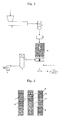
- Fig. 1 shows an example of an apparatus for producing a fibrous toner precursor (hereinafter referred to as fibrous toner) of the present invention.
- the apparatus contains an extruder 2, a static mixer 3, a gear pump 4, a gas heating unit 6, a gas supplying unit 5, and a distribution flow path unit 100.
- the present invention is characterized in that, by using the apparatus, a kneaded material containing any of a resin, wax, pigment and charge controlling agent is melted or diluted with a solvent, and extruded from an extrusion nozzle and the melted/dissolved material from the extrusion nozzle is drawn by high-temperature high-pressure gas flow supplied from a slit-shaped laval nozzle having acceleration mechanism so as to process the extruded material into a fine fibrous shape.
- the shape of the nozzles and the condition of' gas flow are so optimized that a toner precursor having superior quality to the conventional ones can be produced
- an apparatus for producing an electrophotographic toner in which a toner constituent material is extruded from a nozzle hole and then drawn by high-pressure gas flow so as to be processed into a fibrous shape, has a unit configured to feed a raw material fluid to the nozzle hole by tapering at an appropriate angle.
- discharge pulsation can be decreased and more uniform fibrous toner having less variation in the fiber diameters can be obtained.
- the apparatus for producing an electrophotographic toner having the unit configured to feed the raw material fluid to the nozzle hole by tapering at an appropriate angle, enables to avoid generation of accumulated materials in a flow path and enables to make a thermal history of the raw material fluid uniform, and thus homogenous raw material fluid can be fed to each nozzle.
- short-term and long-term variations in physical properties of the fibrous toner are decreased and a fibrous toner having less variation in the fiber diameters and better quality can be produced.
- the angle at which the structure of nozzle unit tapering toward the nozzle hole is 2° to 20°, preferably 3° to 17°, and more preferably 3.5° to 15°.
- the nozzle having an angle of 15° or less can prevent formation of, so-called, polymer die, or accumulation part, and suppress formation of a deteriorated substance in rheological, physical properties of the raw material suitable for a toner. Moreover, an apparatus capable of producing a fibrous toner which can produce a toner having superior physical properties can be provided.
- the nozzle having an angle of 2° or less needs longer distance for taper and makes the apparatus size larger; thus, it is not rational as an apparatus or component.
- the nozzle having an angle of 2° or less does not form a polymer die, and a functional problem does not occur.
- the lower limit is set, for example, 2° or more, more preferably 3° or more, and still more preferably 3.5° or more so as not to be an irrational size as the apparatus or component.
- the lower limit is not limited thereto, when the configuration is based on a rational design concept such as dimensional coordination.
- tapering units include a conically- tapering configuration, and a slit flow path configured to be thinner.
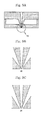
- Linearly aligned nozzle holes are, for example, the nozzle holes viewed from a side of a nozzle hole outlet as shown in Fig. 2.
- circular nozzle holes are aligned at equal intervals Slits that are disposed in parallel across the nozzle holes are nozzles where high-temperature gas flows are discharged.
- the gas flow supplied at an angle to a direction of' the nozzle is, for example, shown in Figs.. 3A and 4..
- Fig.. 3A shows a cross-sectional view vertical to an alignment direction of' nozzle holes in a nozzle unit having aligned nozzle holes.
- slits where high-temperature gas flows are discharged are disposed across the nozzle holes.
- Fig. 4 is an enlarged view of a tip of the nozzle hole.. As shown in Fig. 4, the high-temperature gas flow is supplied along a wall of a nozzle tip.
- a mechanism tapering toward the nozzle hole in the nozzle unit is, for example, a configuration as shown in Fig.. 3A.
- the flow path is gradually narrowed from upstream to downstream.
- the flow path may have a tapered configuration having a step in order to change an angle at a certain position and to adjust position or distance, in view of configuration or fabrication.
- the nozzle preferably tapers at an angle of 2° to 20°.
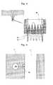
- a nozzle unit having aligned nozzle holes is as shown in Fig. 8.
- Fig. 8 shows a cross sectional view parallel to a direction of' aligned nozzle holes through the center of each nozzle hole.
- the tip of the nozzle hole preferably has a straight body part which will be explained hereinafter and upstream of the straight body part is preferably configured to conically taper
- the straight body part conically tapers preferably at 2 °C to 45 °C, and more preferably at 10° to 30°.
- a high-temperature gas is collided into the tip of the nozzle hole at a certain angle to a direction toward the nozzle, so that energy is efficiently transferred to the raw material flow.
- the high-temperature gas is preferably supplied at 15° to 33° and preferably 18° to 27° in view of the balance with drawing properties of the toner raw material.
- the means for increasing discharge speed include a means for increasing supply pressure of the high-temperature gas flow, and a means for using low-molecular mass gas such as hydrogen and helium as the high-temperature gas.
- inert gas such as nitrogen gas or argon gas may be used.
- the pressure of' the high-pressure gas is preferably approximately 0 kPa to 500 kPa, more preferably 0 kPa to 200 kPa, and still more preferably 0 kPa to 100 kPa..
- the temperature of the high-pressure gas is 150°C to 350°C, preferably 170°C to 280°C, and more preferably 180°C to 250°C.
- gas heating units examples include known electric heaters, steam heaters and gas heaters.
- Known toner has an average particle diameter of 12 ⁇ m or less, and when fibrous toner is processed by a pulverization/cut apparatus capable of pulverization or cutting of fibrous toner, the cut length is approximately 1.2 to 1.5 times as large as fiber diameter on average. For this reason, in general, toner particles having good quality cannot be obtained unless the fiber diameter is made to be 8 ⁇ m or less.
- the coefficient of variation in the fiber diameters is preferably at least less than 17, and more preferably less than 16.
- an apparatus which uses a mixture fluid in which a raw material A containing at least a resin and a pigment is diluted with a raw material B containing at least one of' a low melting point resin, wax and organic solvent, and in which the mixture fluid is extruded from an extrusion nozzle unit having a plurality of aligned extrusion nozzle holes controlled at 150°C to 320°C while controlling its flow rate.
- 3% by mass or more, more preferably 5% by mass or more, of the raw material B is further contained, whereby the apparent viscosity of the total raw material fluid (melted raw material, dissolved raw material, or slurry raw material) decreases, resulting in increased processibility of the fibrous toner.
- Examples of the resins for the raw material A include styrene mono-polymers such as polystyrenes, poly-p-chlorostyrenes, polyvinyltoluenes, and substituted styrenes ; styrene copolymers such as styrene-p-chlorostyrene copolymers, styrene-vinyltoluene copolymers, styrene-vinylnaphthalene copolymers, styrene-acryl ester copolymers, styrene-methacrylate copolymers, styrene- ⁇ -chloromethylmethacrylate copolymers, styrene-acrylonitrile copolymers, styrene-vinylmethylether copolymers, styrene-vinylethylether copolymers, styrene-vinylmethylketone
- pigments for the raw material A include inorganic pigments such as chrome yellow, zinc yellow, barium yellow, cadmium yellow, zinc sulfide, antimony white, cadmium red, barium sulfate, lead sulfate, strontium sulfate, zinc white, titanium white, colcothar, iron black, chromium oxide, aluminum hydroxide, calcium silicate, ultramarine blue, calcium carbonate, magnesium carbonate, carbon black, graphite, aluminum pigment powder, bronze powder, and organic pigments such as Madder lake, Logwood lake, cochineal lake, naphthol green B, naphthol green Y, naphthol yellow S, lithol fast yellow 2G, permanent red 4R, brilliant fast scarlet, hansa yellow, lithol red, lake red C, lake red D, brilliant carmine 6B, permanent red F5R, pigment scarlet 3B, bordeaux 10B, phthalocyanine blue, phthalocyanine green, sky blue, rhodamine lake,
- the raw material A may contain a charge controlling agent and a magnetic material.
- the charge controlling agent include plant wax such as candelilla wax, carnauba wax, rice wax; mineral wax such as montan wax, ceresin wax; petroleum wax such as paraffin wax, petrolatum; synthetic hydrocarbons such as polypropylene, polyethylene; hydrogenated wax such as hardened castor oil, hardened castor oil derivative; fatty acid derivative such as alcohol, ester, amide, imide, ketone, and metal soap.
- the magnetic materials include magnetite, ferrite and iron oxide.
- Examples of the low melting point resins of' the raw material B include styrene mono-polymers such as polystyrenes, poly-p-chlorostyrenes, polyvinyltoluenes, and substituted styrenes; styrene copolymers such as styrene-p-chlorostyrene copolymers, styrene-vinyltoluene copolymers, styrene-vinylnaphthalene copolymers, styrene-acryl ester copolymers, styrene-methacrylate copolymers, styrene- ⁇ -chloromethylmethacrylate copolymers, styrene-acrylonitrile copolymers, styrene-vinylmethylether copolymers, styrene-vinylethylether copolymers, styrene-vinyl
- wax for the raw material B examples include plant wax such as candelilla wax, carnauba wax, rice wax; mineral wax such as montan wax, ceresin wax; petroleum wax such as paraffin wax, petrolatum; synthetic hydrocarbons such as polypropylene, polyethylene; hydrogenated wax such as hardened castor oil, hardened castor oil derivative; fatty acid derivative such as alcohol, ester, amide, imide, ketone, and metal soap. These may be used alone or in combination.
- organic solvents for the raw material B include hydrocarbons such as hexane, octane, petroleum ether, cyclohexane, benzene, toluene, and xylene; ethers such as ethyl ether, dimethyl glycol, trioxane and tetrahydrofuran; acetals such as methylal and diethylene acetal; ketones such as acetone, methyl ethyl ketone, methyl isobutyl ketone, and cyclohexane; esters such as butyl formate, butyl acetate, ethyl propionate, and cellosolve acetate; acids such as formic acid, acetic acid and propionic acid; sulfur- or nitrogen-containing organic compounds such as nitropropene, nitrobenzene, dimethylamine, monoethanolamine, pyridine, dimethylsulfoxide, and dimethylformamide.
- hydrocarbons such as hexane
- a kneader such as a known extruder
- methods for controlling the flow rate include a method for controlling volume flow by a known gear pump, a method for controlling the flow rate by means of a rotation number of an extruder, and a method for controlling the flow rate by means of feed rate of a feeder configured to feed the raw material.
- known feeders for powder or fluid may be used
- mass variation specifically, a decreased amount of mass per unit time may be used.
- a collision state between the nozzle hole outlet and gas flow is so controlled that the variation in the thickness of' the fibrous toner becomes less, or uniformity of the variation is improved, and yield is increased.
- the shortest distance of the center of the outlet opening of the nozzle, or an opening surface of' the nozzle hole, and the nozzle hole surface of the gas nozzle is preferably 0.5D to 3D, more preferably 0.7D to 2D in view of improvement of yield
- fiber diameter is correlated to feed rate per nozzle (i.e., feed rate increases/decreases with increasing/decreasing fiber diameter, though not proportionally), and the feed rate is a control factor of the fiber diameter in the apparatus
- Nozzles of smaller diameter are suitable to obtain finer fibrous toner
- the nozzle diameter is preferably 2D or less in view of necessity of controlling the fiber diameter to a smaller diameter for manufacturing reasons.
- a suitable draw ratio is such that a ratio of "D/fiber diameter DB" is 10 fold to 200 fold, and more preferably 20 fold to 50 fold.
- the shortest distance between the center of the opening surface of the nozzle hole and the nozzle hole surface of the gas nozzle means a shortest distance between the center of the nozzle hole and the gas nozzle part.
- 31 denotes a tip of the nozzle hole
- 32 denotes a slit where high-temperature gas flow is discharged.
- the raw material of the above-described toner material generally shows Barus effect in the nozzle outlet.
- the Barus effect is, for example, as shown in Fig. 4, a phenomenon in which the diameter of an extruded material becomes larger immediately after discharge from the nozzle hole. After the resin is extruded from the nozzle hole, it once increases its diameter by Barus effect, and then drawn by the gas flow.
- the fibrous toner When the shortest distance is 3D or more, similarly, the fibrous toner is nonstationarily cut, and fused with an adjacent fibrous toner by vibration for aggregation.
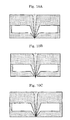
- the discharging surface of the nozzle hole and gas nozzle can be preferably controlled up and down as shown in Figs, 10A to 10C as a production apparatus.
- Fig. 10A shows a state in which a nozzle hole surface and a slit nozzle surface of the high-pressure gas flow are arranged on the same surface.
- Fig. 10B shows a positional relation in which the nozzle hole surface is projected beyond the slit nozzle surface of' the high-pressure gas flow.
- Fig. 10C shows the nozzle hole surface arranged inside the slit nozzle surface of the high-pressure gas flow..
- An adjustment margin between the nozzle hole surface and the slit nozzle surface is substantially approximately 5D to 10D relative to the opening diameter D of' the nozzle..
- the positional relation among the nozzle hole, nozzle unit and slit nozzle of the high-pressure gas flow is optimized by the shapes of components according to resin's physical properties. The positional relation can be further optimized by providing the adjustment margin, when the same components are used.
- collision state of' the extruded material to the high-temperature gas flow is finely adjusted so as to improve the stability of making into the fibrous shape (for example, improvement of continuity of the fibrous toner, less variation in the fiber diameters and the like).
- the amount of discharge and flow condition of the extruded material from the nozzle hole are stabilized by controlling the shape of the nozzle hole, and thus more uniform fibrous toner can be obtained.
- the nozzle hole preferably has a circularity of 09 or more, and more preferably 0.95 or more.
- the straight body part having a length of 5D or more stabilizes discharge amount and the flow direction of the extruded material.
- the straight body part preferably has a length of 5D to 12D.
- the nozzle preferably has an outlet opening of circle-converted diameter D of' 100 ⁇ m to 400 ⁇ m.
- the straight body part for the nozzle hole is, for example, as shown in Fig. 7.
- the nozzle hole tapers toward the nozzle hole outlet, and has the straight body part which has the same shape as the outlet hole,
- the pitch is 1.5 mm or more
- the flow direction of the fibrous toner is not stable, and the fibrous toner unevenly contacts the high-temperature gas flow, and variation in the fiber diameter in each nozzle becomes larger, thereby decreasing yield.
- the nozzle having a circularity of 0.9 or more leads to less variation in the fiber diameters, and improvement of yield.
- a circularity of 0.9 or more enables to stabilize the flow direction, and the possibility that extruded materials contact each other between adjacent nozzles is decreased.
- the nozzle pitch may be 3.3D at minimum, and thereby production capacity and energy efficiency are dramatically improved per an apparatus scale.
- the nozzle hole is a prefect circle, and the value becomes smaller as the nozzle hole deviates in shape from the prefect circle.
- the production capacity of this apparatus is inversely proportional to nozzle pitch and energy consumption is proportional to nozzle pitch.
- the pitch When the pitch is less than 3.3D and the straight body part has a length of 15D, it caused cracks and damages to the nozzles of' the nozzle unit when the taper angle immediately anterior to the nozzle and angle of supplying gas flow fall in the above-described ranges. Thus, the pitch of less than 3.3D is judged that nozzles fail to have a sufficiently-safe hardness as a production apparatus.
- the straight body part is required to have a length of a certain ratio and above for the following reasons:
- a measured result is analyzed using a data analysis software TA-60 version 1. 52 by Shimadzu Corporation.
- TA-60 version 1. 52 by Shimadzu Corporation.
- the maximum peak point ⁇ 5 °C is designated as the range to obtain the peak temperature of the sample using the peak analyzing function of the analysis software.
- the maximum endothermic temperature in the DSC curve of' the sample in the range +5 °C to -5 °C is obtained using the peak analyzing function of' the analysis software.
- the temperature indicated by the analysis software corresponds to the melting point (Tg) of the toner.
- the temperature from posterior to extruder to immediately anterior to the nozzle unit is based on the temperature of the extruder. However, it may be generally higher than the temperature of the extruder.
- the nozzle and the nozzle unit preferably have a temperature of T1/2 to T1/2 ⁇ 2 When the toner raw material is used, it is preferably approximately 100°C to 250°C, more preferably 140°C to 250°C, and still more preferably 150° to 240°C.
- a differential pressure ⁇ P of anterior and posterior to the gear pump is preferably small in view of constant feed amount.
- the pressure posterior to the gear pump is preferably 15MPa or less, more preferably 10MPa or less, and still more preferably 9MPa or less in view of durability.
- toner particles having a sharp particle size distribution are obtained by pulverizing a fibrous toner precursor having less variation in the fiber diameters.
- the fibrous toner precursor is produced by the method of the present invention which satisfies the above requirements, whereby production efficiency of' the fibrous toner precursor can be improved, and yield and particle size distribution obtained by a method for producing toner particles, in which the fibrous toner precursor is cut and pulverized by means of' a known method can also be improved.
- the fibrous toner precursor is pulverized by a mechanical pulverizer, a high pressure airflow pulverizer and the like.
- the mechanical pulverizers include KRIPTRON by Kawasaki Heavy Industries, Ltd., a turbo mill by TURBO KOGYO CO., LTD. and an inomizer by Hosokawa Micron Corporation.
- the high pressure airflow pulverizers include a counter jet mill by Hosokawa Micron Corporation, and an IDS pulverizer by Nippon Pneumatic Mfg. Co., Ltd.
- a mechanical pulverizer equipped with a built-in classifier is more preferred.
- pulverizers such as cutter, knife, pin-type pulverizers and other common pulverizer may be used. Additionally, the above pulverizers combined with a screen and/or a wind force classifier and the like can be used.
- coarse pulverization and medium pulverization it is only required that the fibrous toner precursor be cut to a level that can ensure smooth feeding of cut fibrous toner precursor into a fine pulverizer; it is only required that the fibrous toner precursor be cut to pieces of approximately several centimeters to several millimeters
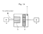
- Fig. 12 shows a schematic view of an example of an entire apparatus for producing a fibrous fine resin particle precursor.
- a supplying unit for a gaseous substance is provided in a known apparatus for producing fine resin particle precursor (a spinning apparatus).
- the fibrous precursor has air gaps inside and thus hardness in each part of the fibrous precursor varies at a micro level; therefore the fiber tend to undergo breakage (the same effect brought about by air bubbles and pulverizing aids disclosed in JP-A 2005-004182 ).
- fine particulation of fibrous fine resin particle precursor for example, by means of pulverization and cut (hereinafter collectively referred to as "pulverization") becomes easy, and production capacity is improved and process energy is decreased.
- pulverization pulverization
- any known method may be used for the method for producing the fibrous precursor.
- a resin is extruded from a pipe sleeve and may be drawn by pulling and winding using a roller, or may be drawn by high-temperature air for spunbonding and melt blowing.
- a dry spinning using a solvent, and a wet spinning using a reaction solution may be used depending on the resin system.
- the method for making into a fiber shape is not particularly limited.
- a temperature of a heating machine and kneading machine during heating and melting is preferably set at Tg or more of the resin to Tg ⁇ 4 or less of the resin, more preferably at Tg ⁇ 1.5 or more to Tg ⁇ 3 or less of the resin.
- the heating machines and kneading machines include those commonly used, so-called an extruder, kneader, heating pot, but not limited thereto.
- the size (thickness) of the air gaps inside the fibrous fine resin particle precursor is preferably not over one-third as thick as fiber diameter, and more preferably not over one-fourth as thick as fiber diameter.
- Many of the air gaps have shapes extended along the long axis direction of the fiber by necessity due to the drawing effect.
- the thickness of the air gap is obtained from the diameter of' the cross section of' an air gap cut along a plane vertical to the long axis direction of the fiber.
- the porosity which substantially corresponds to an area ratio of air gaps over a cross section of a fiber, is 10% to 55%, preferably 13% to 50% and more preferably 15% to 40%. Too large porosity results in easy breakage of fiber structures in its thickness direction when the fiber is made into fine particles, generating a large amount of' fine powder.
- the fiber diameter is defined as the diameter measured at the narrowest point across a fiber piece section
- the thickness of an air gap is defined as the diameter of a section of' an air gap located at the same place as the fiber piece section.
- Fig. 13A shows a cross sectional view of an internal structure in a long axis direction of the fibrous fine resin particle precursor
- Fig.. 13B shows a cross sectional view of an internal structure in a short axis direction of the fibrous fine resin particle precursor.
- the fibrous fine resin particle precursor having therein air gaps 61 can be obtained by mixing gas with a resin before the fibrous fine resin particle precursor made into a fiber shape.
- gas when the gas is dissolved in the resin, more uniform air gaps can be formed. And then, each part of the fibrous fine resin particle precursor becomes macro-uniform so as to suppress broad particle size distribution and generation of' the fibrous fine resin particle precursor having a part which is difficultly pulverized
- gas include nitrogen, carbon dioxide and butane gases which are generally highly soluble to resins and easily form uniform air bubbles.
- nitrogen and carbon dioxide gases are more preferable
- the apparent viscosity of a mixture containing the gas and resin decreases by mixing of' gas in the resin, and thus extrusion energy from a pipe sleeve is decreased when the fibrous fine resin particle precursor is made into a fiber shape.
- the mixture of the gas can decrease the heating temperature when extruding, and may effect to prevent degradation of the resin
- the gas dissolved in the resin is more preferred because the viscosity of' the resin is further decreased, and heating temperature can be decreased.
- any method known in the art can be used.
- An extruder, static mixer or the like may be used for mixing. Any known appropriate apparatus can be used.
- the mixing ratio of the gas may be set according to a desired porosity.
- the porosity is preferably 10% to 50%, more preferably 13% to 45%, and still more preferably 15% to 40%
- a gas having a volume corresponding to the porosity may be supplied in order to achieve that porosity Specifically, a larger amount of gas is fed to obtain larger porosity, and a small amount of gas is fed to obtain a small porosity.
- the volume of the gas changes depending on temperature and pressure, but a value obtained in the standard state can be used on production technology Specifically, when air is used, the volume of air gaps and porosity are found from the air volume when it is assumed that air has an average molar mass of 29g/mol, a volume of 22..4L in the standard state, i.e., density of 1.29kg/m 3 . In the same way, for example, the volume of air gaps and porosity are found using the average molar mass of carbon dioxide (40g/mol), or average molar mass of nitrogen (28g/mol)
- the specific gravity of basic components of' the toner specifically, a resin, pigment, charge controlling agent and wax may vary in a range from 1,000 kg/m 3 to 1,300 kg/m 3 depending on their formulations. Technically, a specific gravity of 1,150 kg/m 3 is sufficient.
- the size (thickness) of the air gap can be controlled mainly by changing a mixing condition. For example, when finer air bubbles are formed, larger mixing force (kneading) is given after the gas is supplied, and the number of the elements of mixer may be increased to obtain finer air bubbles by using the static mixer
- the air bubbles may be united in a mixing process, even after the air bubbles are finely dispersed.
- a gas highly soluble to the resin is selected to suppress reunion of the air bubbles in the mixing process; for example, butane and carbon dioxide gases can be suitably used.
- a gas in the supercritical state may be used in terms of' high solubility. Examples thereof include carbon dioxide and nitrogen gases in the supercritical state.
- a porosity of more than 60% causes fine cracks when the fibrous fine resin particle precursor is made into fine particles, and particle size distribution after fine particulation becomes broad. When the porosity is too small, easiness of' fine particulation cannot be improved.
- the gas becomes easily dissolved in the resin by mixing it in a supercritical state, and air gaps are more uniformly formed. Moreover, the resin and the gas are uniformly mixed when the gas is mixed in a supercritical state and then made into a fiber shape, and the fiber diameters easily becomes uniform when made into a fiber shape, as compared to a case where the gas is not in the supercritical state.. As a result of the above two effects, more uniform fine resin particles can be easily obtained.
- a method for mixing the gas in the supercritical state those known methods can be used An extruder, static mixer or the like may be used for mixing.
- the methods for mixing are not limited but a known static mixer is preferably used by means of a melt spinning..
- the size (thickness) of the air gap can be controlled mainly by changing a mixing condition. For example, when finer air bubbles are formed, larger mixing force (kneading) is given after the gas is supplied, and the number of' the elements of mixer may be increased to obtain finer air bubbles by using the static mixer.
- a gas highly soluble to the resin is selected to suppress reunion of the air bubbles in the mixing process; for example, butane and carbon dioxide gases can be suitably used.
- a gas in the supercritical state may be used in terms of high solubility. Examples thereof include carbon dioxide and nitrogen gases in the supercritical state. It is useful to use a gas having high solubility and a gas in the supercritical state, even when the porosity is small, for the purpose of more uniformly dispersing air bubbles.
- the thus produced fibrous fine resin particle precursor is extremely excellent to obtain uniform fine particles and able to apply to an electrophotographic toner
- the toner is needed to have a uniform particle size distribution
- the amount of resin per particle can be decreased when the particle diameter by appearance is such that the volume average particle diameter (D50) is 4 ⁇ m to 8 ⁇ m within which high handling ability is obtained.
- D50 volume average particle diameter
- the thickness of a toner layer in each dot can be thin compared to toner particles having the same particle diameter. Therefore, particularly a color toner taking advantage of' the fibrous fine resin particle precursor can form an image excellent in quality.
- a minimum amount of toner attached per color of a color toner needs at least one layer based on toner particle.
- an image consists of about two layers of' toner particles, and a four-color image consists of about 8 layers.
- a toner having a particle size of 8 ⁇ m is used, an fixed image having a thickness of' about 60 ⁇ m.
- thickness variations over a fixed color image can be reduced, and discomfort to the image can be removed.
- the toner consumption can be decreased by increasing the porosity of the toner, when particle size is reduced or is constant.
- the toner particles lend themselves well to health issues. Recent years, the likelihood of fine particles deposition in the respiratory organ has become controversial, and it is said that the limit particle size (lower limit of particle size) of dry toner particles, above which human can handle with safety, is 3 ⁇ m to 4 ⁇ m. However, the porosity of' the particles is made larger so that the lower limit can be substantially decreased because the deposition in the respiratory organ depends on aerodynamic diameter. Specifically, the toner will possibly have a smaller diameter and accordingly improve image quality in future.
- nozzle holes having circle-converted diameter of 190 ⁇ m were aligned on the center line of a surface having a width of 0.4mm.
- a mixture was melted and kneaded by an extruder, and further extruded and fed in a melted state (150°C) to the next step.
- the melt material was passed through a static mixer kept at 1.90°C, and was extruded from nozzle holes formed on an extrusion nozzle unit, while the volume flow rate was adjusted at 0.14cc/min in each nozzle hole by a gear pump..
- a small unit was used, and therefore the raw material was distributed to each nozzle with a single step by means of' a fan-shaped distribution flow path.
- a structure as shown in Fig. 6 was adopted as the fan-shaped distribution flow path 24.
- the extruded material was drawn from the gas nozzle by a hot air at 220°C as a high-temperature gas flow for drawing, to obtain a fibrous fine particle precursor.
- Each unit posterior to the static mixer was kept at 220°C
- a high-temperature gas (air) was supplied at 1.3m3/s (at 25°C under 1 atmospheric pressure) per 1 mm of' the nozzle unit.
- the gas nozzle was a nozzle having 0.5 mm slit-like two lines running in parallel across tandemly-arranged nozzle holes as shown in Figs.. 2 and 3A to 3B.
- 250 fibers were sampled about 1 hour after start of operation, and each thickness thereof was measured using an optical microscope.
- the fibers extruded from the 50 nozzle holes were sampled from each nozzle 5 times: 50 min., 55 min., 60 min., 65 min. and 70 min. after running was started.
- the thickness of' the sampled fiber was measured at any part to obtain a fiber size distribution including variation in each nozzle and variation in each nozzle at each time of sampling.
- An average fiber diameter and standard deviation were obtained from the fiber size distribution, and a coefficient of variation was further obtained. The finer average fiber diameter a fiber had, the more efficiently it was drawn, and the smaller coefficient of variation a fiber had, the more uniformly it was formed.
- discontinuous Reference Condition 2 slightly discontinuous 7.91 1.52 19.22 Large amount of adhesion around the nozzle.
- slightly discontinuous Comparative Condition 5 slightly discontinuous 6.98 1.21 17.34 Pulsation of fiber diameter. Large amount of adhesion around the nozzle.
- slightly discontinuous Comparative Condition 6 slightly discontinuous 7.43 1.69 22.75 Pulsation of fiber diameter. Large amount of adhesion around the nozzle.
- discontinuous Comparative Condition 3 slightly discontinuous 7.33 1.75 23.87 Significant pulsation of fiber diameter. Large amount of adhesion around the nozzle.
- discontinuous Comparative Condition 4 slightly discontinuous 7.83 2.1 26.82 Considerable pulsation of fiber diameter. Large amount of adhesion around the nozzle.
- discontinuous Comparative Condition 7 slightly discontinuous 7.36 1.65 22.42 Slight pulsation of fiber diameter. Large amount of adhesion around the nozzle. slightly discontinuous Comparative Condition 8 slightly discontinuous 6.98 1.21 17.34 Pulsation of fiber diameter. Large amount of adhesion around the nozzle. slightly discontinuous Comparative Condition 9 slightly discontinuous 7.36 1.65 22.42 Slight pulsation of fiber diameter. Large amount of adhesion around the nozzle. slightly discontinuous
- slightly discontinuous Implementation Condition 4 continuous 6.74 0.82 12.17 Slightly large amount of adhesion around the nozzle.
- slightly discontinuous Implementation Condition 5 continuous 6.02 0.52 8.64 Small amount of adhesion around the nozzle.
- continuous Implementation Condition 7 continuous 4.87 0.44 9.03 Small amount of adhesion around the nozzle.
- continuous Implementation Condition 9 continuous 6.61 1.04 15-73 Slight pulsation of fiber diameter. Large amount of adhesion around the nozzle.
- slightly discontinuous Implementation Condition 10 continuous 6.78 1.08 15.93 Slight pulsation of fiber diameter. Large amount of adhesion around the nozzle.
- slightly discontinuous Implementation Condition 11 continuous 6.78 1.02 15.04 Slight pulsation of fiber diameter. Large amount of adhesion around the nozzle.
- slightly discontinuous Implementation Condition 12 continuous 6.74 0.84 12.46 Slightly large amount of adhesion around the nozzle.
- slightly discontinuous Implementation Condition 13 continuous 6.74 0.8 11.87 Slightly large amount of adhesion around the nozzle.
- slightly discontinuous Implementation Condition 14 continuous 6.02 0.54 8.97 Small amount of adhesion around the nozzle.
- Implementation Conditions 3, 9 and 10 are improvements on Comparative Conditions 5, 6, 8 and 9.
- the condition of the fiber was slightly discontinuous, but improved compared to Comparative Conditions.
- the pulsation of the fiber diameter was at a level that was barely visually observed with a microscope..
- the improvement of the condition of the fiber was clear from a decreased coefficient of variation in spite of' a reduced fiber diameter.
- the fiber diameter was reduced although the same amount of the high-temperature gas flow was used. This indicated improvement of' energy efficiency.
- the characteristic structure of' the nozzle outlet part of the present invention (an area of vertical surface) was satisfied, so that the fibrous toner precursor having narrow fiber size distribution could be obtained more efficiently than conventional methods.
- Implementation Conditions 4 and 12 are improvements on Implementation Condition 3. The reduction of the fiber diameter and coefficient of variation were also observed. Additionally, the pulsation of the fiber diameter was reduced. Implementation Conditions 4 and 12 satisfied the condition of the length of the straight body part of the nozzle which was one of' the characteristic structures of the present invention, and showed improvement over Implementation Condition 3, for example, the coefficient of variation of the fiber diameter became small. In comparison of Implementation Condition12 with Implementation Condition 11, the variation in the fiber diameters, specifically, the coefficient of' variation was remarkably improved, because the length of the straight body part was approximately more than 5D.
- Implementation Condition 5 and 14 satisfied the condition of the nozzle circularity in the apparatus of the present invention, and are improvement on Implementation Condition 4..
- the condition of circularity of the present invention was satisfied, so that the adhesion around the nozzle was reduced and uniform fiber could be produced more efficiently.
- Implementation Condition 14 the variation in the fiber diameters, specifically, the coefficient of variation was remarkably improved, because the circularity was approximately more than 0.9.
- the fiber diameter was reduced and energy efficiency was improved.
- the fiber was drawn by subjecting the entire fiber from the nozzle outlet to downstream to pulling by air current. The amount of the fiber which enjoyed the benefits of pulling by air current due to improvement on continuity of the fiber, and energy efficiency might be improved.
- Implementation Condition 7 was an improvement by adopting a laval structure relative to Implementation Condition 5.
- the fiber diameter was significantly reduced. Considering that the fiber diameter was significantly reduced, it was evaluated that increase in the coefficient of variation was within the acceptable error range, and the energy efficiency was significantly improved.
- Circular nozzles having a diameter of 190 ⁇ m were aligned on the center line of a surface having a width of 0.4 mm.
- Comparative Example A-2 a unit, in which 501 nozzle holes were aligned at a center distance (pitch) of 0.9 mm intervals was used. The state of the alignment is shown in Fig.. 2.
- 2,500 fibers were sampled about 1 hour after running was started, and each thickness thereof was measured by an optical microscope. Specifically, the fiber were extruded from 500 nozzle holes were sampled from each nozzle 5 times, 50 min., 55 min., 60 min.., 65 min. and 70 min. after running was started. A thickness of the sampled fiber was measured at any part to obtain a fiber size distribution including variation in each nozzle and variation in each nozzle at each time of sampling. An average fiber diameter and standard deviation were obtained from the fiber size distribution, and a coefficient of variation was further obtained.. The finer average fiber diameter a fiber had, the more efficiently it was drawn, and the smaller coefficient of variation a fiber had, the more uniformly it was formed.
- “Standard Condition B” is 10 times the condition of Implementation Condition 7 in terms of scale, under which uniform fibers were most efficiently produced in Example A-1.
- the evaluation result of the obtained fibrous toner is shown in Table 6.
- non-uniform discharge amount was observed in nozzles. Specifically, the wax component in the raw material was separated and sprayed from certain nozzles continuously, or in some cases intermittently This non-uniformity was observed in each fan-shaped unit, or in each distribution flow path of the tournament form.
- the apparatus condition and the like other than "Standard Condition B" are shown in Table 7.
- the evaluation results of the obtained fibrous toner are shown in Table 8.
- Table 7 Twisted mixing structure of distribution flow path Implementation Condition 8
- Adopted Table 8 Condition of fiber (After 1 hour) Average fiber diameter (After 1 hour) Standard deviation (After 1 hour) Coefficient of variation (After 1 hour) Remarks (After 1hour) Implementation Condition 8 continuous 4.85 0.45 9.28 Small amount of adhesion around the nozzle.
- a twisted mixing structure of' distribution flow path was denoted by 26 in Fig 6, and a mixing mechanism is disposed anterior to each branch in Example A-2.
- the toner particles had a sharper particle size distribution than that described in JP-A 2006-106236 , and thus effect of' improvement was sufficiently confirmed.
- the first embodiment of the present invention can be applied to resin filler materials such as a powder coating and liquid crystal, and a toner for an electronic paper, and other resin particles.
- melt blowing which is a kind of' a melt spinning method, was used as a spinning method.
- a spinning apparatus contains as main components an extruder 52, a gear pump 54, a static mixer 53, a gas supplying unit 55 containing a gas supplying source 55' such as tank or cylinder and a pump 55", a nozzle unit containing a spinning die and air nozzle for drawing 57, a pressure gage 58 and a raw material screw feeder 51, which are all known components.
- a gas was supplied from a static mixer part for mixing.
- a pressure resistance 59 was provided in case of' supercritical state
- a nozzle unit having an overall length of approximately 500 m, a nozzle hole diameter of 180 ⁇ m, the number of nozzle holes of 501, and a center distance between the nozzle holes (pitch) of' approximately 0.9 mm was used.
- the temperature from the extruder to the gear pump was set at 150°C and the temperature of' a spinning pack and spinning nozzle unit was set at 200°C or 220°C and kept constant.
- the gas nozzle had a slit width of 0.5 mm and used air was maintained at 3.6m 3 /h at 50 °C under 1 atmospheric pressure.
- the high-temperature gas was maintained at 200°C.
- the amount of extrusion was set such that the fiber diameter D50 is 6.0 ⁇ 0.1 ⁇ m as measured with an evaluation method of a fiber diameter to be described hereinafter.
- One fiber was sampled from each nozzle and the thickness thereof was measured with an optical microscope Specifically, the fibers were extruded from 501 nozzle holes, and sampled from each nozzle 3 times at 5-minute intervals. The thickness of the sampled fiber was measured at any position to obtain an entire fiber size distribution. The average fiber diameter and standard deviation were obtained from the fiber size distribution, and a coefficient of' variation was further obtained. The smaller the average fiber diameter a fiber had, the more efficiently it was drawn, and the smaller the coefficient of variation a fiber had, the more uniformly it was formed.
- a known mechanical pulverizer was used for pulverization.
- the fiber was precut to have a length of several millimeters by a known cutter mill before fed to the pulverizer.
- pulverizers such as KRIPTRON by Kawasaki Heavy Industries, Ltd., a turbo mill by TURBO KOGYO CO., LTD. and an inomizer by Hosokawa Micron Corporation can be used.
- a mechanical pulverizer equipped with a built-in classifier was used, such as a pulverizer having therein a rotary wind-driven classifying mechanism and equipped with a spinning rotor type pulverizing rotor, like the foregoing inomizer, for convenience of arranging laboratory equipment.
- Fig. 14 shows a structure of the pulverizer equipped with a built-in classifier.
- the pulverizer includes a pulverizing rotor 72 having a diameter of approximately 30 cm and a classifying rotor 73 having a diameter of approximately 18 cm, which are integrated in a cylinder container.
- the feeding amount of the raw material 71 was adjusted to a condition that the pulverizing rotor 72 had a consumption power of 8kW.
- the fine particulation was evaluated by comparing a CV value obtained from particle size distribution, and a power per unit processed amount obtained from a total power required for pulverization with the pulverizing power of 8 kW and classification..
- the total power was obtained in such a way that an idle value of each of pulverizing and classifying motors 74 were obtained beforehand, and then the idle value was subtracted from a power of running..
- Table B-1 Supply amount of gas based on 100 parts by mass of resin Type of gas Porosity % Nozzle temperature °C Comparative Example B-1 0 - 0 200 Comparative Example B-2 0 - 0 220 Comparative Example B-3 0.200 air 64 200 Example B-1 0.065 air 37 200 Example B-2 0.100 CO 2 39 200 Example B-3 0.100 CO 2 /supercritical 39 200
- Comparative Examples B-1and B-2 a conventional technology was used.
- Example B-1 air was mixed in a resin to form air gaps.
- Example B-2 CO 2 , which has a high solubility to the resin, was mixed in the resin.
- Example B-3 pressure resistance was provided in upstream of the spinning die so as to mix CO 2 in the resin in a supercritical state.
- Table B-1 The supply amounts and types of gas, porosity and nozzle temperatures are shown in Table B-1.
- Table B-2 Fiber diameter ⁇ m Fiber diameter CV Processed amount kg/h Extrusion pressure Mpa Comparative Example B-1 6.1 10.2 2.8 2.1 Comparative Example B-2 6.0 10.5 3.1 1.9 Comparative Example B-3 6.1 15.6 3.7 1.9 Example B-1 6.0 11.3 3.9 1.5
- Example B-2 5.9 10.1 4.6 1.4
- Example B-3 5.9 9.4 4.6 8.0
- Table B-2 shows CV values indicative of' evaluation criteria of a fine particle precursor, processed amounts and extrusion pressures as determined on the assumption that the fiber diameters are the same.
- the CV values of the fiber diameter were good in Comparative Examples B-1 and B-2, and Examples B-2 and B-3.
- the CV value was rather bad in Example B-1. This might be attributed to the fact that the CV values in Comparative Examples were good because the fine particle precursors originally contain no air gaps inside and thus are uniform inside, whereas the CV value was bad in Example B-1 because the fine particle precursor was not uniform inside due to the presence of internal air bubbles.
- Examples B-2 and B-3 some or all of the gas was dissolved in the resin and air gaps were uniformly generated, thus the CV values might be improved to a level comparable to the CV value obtained before the gas was mixed in the resin.
- the extrusion pressures of' Examples B-1 and B-2 were lower than that of Comparative Example B-2 in which the nozzle temperature was higher, and extrusion efficiency was improved.
- Example B-3 the extrusion pressure was high because a pressure resistance was provided to obtain a supercritical state.
- Table B-3 shows results of fine particulation. Consequently, the total power of experiment was approximately equal in each condition, because the power load of' the pulverizing rotor and power load of the classifying rotor, which controlled the power load of the pulverizing rotor at constant, might depend on accumulation in the apparatus However, with regard to the consumption power per unit processed amount, Examples were approximately equally better than Comparative Examples.
- Examples B-1 to B-3 it was considered that the fine particle precursor was promptly pulverized into an appropriate size in the pulverizer and quickly passed through the classifying rotor. In the fibrous precursor having air gaps inside of Examples B-1 to B-3, the processed amount was increased, compared to Examples B-1 and B-2. With regard to the condition of the classifying rotor which maintained the particle diameter D50 of the product, Examples B-1 and B-3 were good, and Example B3 which might have more uniform air gaps was best, and followed by Example B-2.
- Example B-1 the CV value of the fiber diameter was slightly worse than that in Comparative Examples in case of the fibrous precursor The CV value in Example B-1 was better than that in Comparative Examples in case of fine particulation.
- Example B-1 the fiber diameter variation caused upon fine particulation largely affected variation in size of' the fine particles as final-products, compared to the fiber diameter variation caused when making the precursor to a fibrous shape.
- Comparative Example B-3 the consumption power per unit processed amount was decreased but the CV value was increased.
- the increase of the CV value was caused by a high CV value of the fibrous precursor and particularly an increased amount of fine powder.
- generation of coarse particles are suppressed in the classifier contained in the pulverizer.
- excess pulverization caused by collision with a crushing hammer or the classifying rotor cannot be suppressed.
- the precursor had an excessively-high porosity and was structurally weak, so that fine cracks might be easily generated and a larger amount of fine powder might be generated by breaking a structure of' the precursor.
Landscapes
- Physics & Mathematics (AREA)
- Engineering & Computer Science (AREA)
- General Physics & Mathematics (AREA)
- Mechanical Engineering (AREA)
- Textile Engineering (AREA)
- Spectroscopy & Molecular Physics (AREA)
- Developing Agents For Electrophotography (AREA)
Applications Claiming Priority (4)
| Application Number | Priority Date | Filing Date | Title |
|---|---|---|---|
| JP2006246014 | 2006-09-11 | ||
| JP2006301448 | 2006-11-07 | ||
| JP2007214066A JP2008096974A (ja) | 2006-09-11 | 2007-08-20 | トナーの前駆体製造装置及び製造方法、トナー前駆体繊維、トナー製造装置並びに電子写真用トナー |
| JP2007216505A JP5163010B2 (ja) | 2006-11-07 | 2007-08-22 | 樹脂微粒子の製造方法 |
Publications (3)
| Publication Number | Publication Date |
|---|---|
| EP1898265A2 true EP1898265A2 (fr) | 2008-03-12 |
| EP1898265A3 EP1898265A3 (fr) | 2008-05-21 |
| EP1898265B1 EP1898265B1 (fr) | 2014-07-23 |
Family
ID=38962773
Family Applications (1)
| Application Number | Title | Priority Date | Filing Date |
|---|---|---|---|
| EP07116036.0A Ceased EP1898265B1 (fr) | 2006-09-11 | 2007-09-10 | Appareil pour la fabrication d'un précurseur de toner, le procédé pour preparer ce précurseur de toner fibreux et l'appareil pour la fabrication de toner |
Country Status (2)
| Country | Link |
|---|---|
| US (1) | US7662534B2 (fr) |
| EP (1) | EP1898265B1 (fr) |
Cited By (5)
| Publication number | Priority date | Publication date | Assignee | Title |
|---|---|---|---|---|
| CN101967687A (zh) * | 2010-09-20 | 2011-02-09 | 北京化工大学 | 一种多排型静电纺丝喷头 |
| WO2011091251A3 (fr) * | 2010-01-22 | 2011-09-15 | Fiber Web, Inc. | Filière de filage de fibre fabriquée par extrusion-soufflage |
| EP2184767A3 (fr) * | 2008-11-07 | 2012-01-25 | SolarWorld Innovations GmbH | Système de micro-extrusion avec déflection de perles associées d'un jet d'air |
| US8704086B2 (en) | 2008-11-07 | 2014-04-22 | Solarworld Innovations Gmbh | Solar cell with structured gridline endpoints vertices |
| CN116219558A (zh) * | 2023-02-10 | 2023-06-06 | 新创碳谷集团有限公司 | 一种纺丝喷头控制方法、装置及纺丝加工方法 |
Families Citing this family (8)
| Publication number | Priority date | Publication date | Assignee | Title |
|---|---|---|---|---|
| US7790344B2 (en) * | 2007-05-10 | 2010-09-07 | Ricoh Company Limited | Method of preparing powder and toner for electrophotography, and toner therefor |
| JP5333892B2 (ja) * | 2007-06-11 | 2013-11-06 | 株式会社リコー | 造粒・コーティング方法および装置、並びにその方法を用いた電子写真用キャリアのコーティング方法および電子写真用キャリア |
| JP4465371B2 (ja) * | 2007-07-13 | 2010-05-19 | シャープ株式会社 | トナーおよび二成分現像剤 |
| CN102839431B (zh) * | 2012-09-28 | 2014-12-10 | 北京化工大学 | 熔体静电纺丝法批量生产纳米纤维装置及工艺 |
| EP3181738A1 (fr) * | 2015-12-18 | 2017-06-21 | Universidad Politécnica De Madrid | Procédé de production de structures allongées telles que des fibres à partir de solutions polymères par filage d'écoulement d'égouttage |
| US10416583B2 (en) | 2016-03-04 | 2019-09-17 | Hp Indigo B.V. | Electrostatic ink compositions |
| CN108265340A (zh) * | 2018-03-06 | 2018-07-10 | 杨晓波 | 纳米纤维制造装置 |
| CN112639556A (zh) * | 2018-08-31 | 2021-04-09 | 悉尼大学 | 纤维成形工艺 |
Family Cites Families (19)
| Publication number | Priority date | Publication date | Assignee | Title |
|---|---|---|---|---|
| DE1435461C3 (de) * | 1964-02-22 | 1978-04-06 | Fa. Carl Freudenberg, 6940 Weinheim | Spinndüse zum Schmelzspinnen von Fadenscharen |
| US3825380A (en) * | 1972-07-07 | 1974-07-23 | Exxon Research Engineering Co | Melt-blowing die for producing nonwoven mats |
| US3954361A (en) * | 1974-05-23 | 1976-05-04 | Beloit Corporation | Melt blowing apparatus with parallel air stream fiber attenuation |
| KR0125769B1 (ko) * | 1987-11-20 | 1997-12-29 | . | 부직 웨브의 제조방법 |
| JPH0319907A (ja) * | 1989-03-15 | 1991-01-29 | Toray Ind Inc | メルトブロー用ダイ |
| JPH0491267A (ja) * | 1990-08-02 | 1992-03-24 | Toyobo Co Ltd | 極細繊維不織布 |
| US5080569A (en) * | 1990-08-29 | 1992-01-14 | Chicopee | Primary air system for a melt blown die apparatus |
| JPH06138704A (ja) | 1992-09-09 | 1994-05-20 | Fujitsu Ltd | トナー製造方法及びその装置 |
| JP3358015B2 (ja) | 1995-10-19 | 2002-12-16 | 株式会社リコー | 電子写真用トナーの製造方法 |
| JPH09244296A (ja) | 1996-03-07 | 1997-09-19 | Ricoh Co Ltd | 電子写真用トナーの製造方法 |
| US6395443B2 (en) * | 1999-11-29 | 2002-05-28 | Ricoh Company, Ltd. | Toner for developing electrostatic image and process of preparing same |
| JP3550109B2 (ja) | 2001-06-14 | 2004-08-04 | 有限会社末富エンジニアリング | メルトブロー式不織布の紡糸ダイ |
| JP3992224B2 (ja) | 2002-03-20 | 2007-10-17 | 株式会社リコー | 電子写真トナー製造用流動槽式粉砕分級機およびそれを用いたトナーの製造方法 |
| JP4282363B2 (ja) | 2003-04-30 | 2009-06-17 | 株式会社ホソカワ粉体技術研究所 | 樹脂微粒子の前駆体製造装置および製造方法ならびに樹脂微粒子製造装置 |
| JP4192115B2 (ja) | 2003-05-19 | 2008-12-03 | 株式会社リコー | 混練・粉砕方式による電子写真用トナーの製造方法及びそれに用いる混練物 |
| US7438245B2 (en) | 2004-07-13 | 2008-10-21 | Ricoh Company, Ltd. | Milling and classifying apparatus, collision mill, air classifier, toner, and method for producing toner |
| JP4363298B2 (ja) | 2004-10-04 | 2009-11-11 | ホソカワミクロン株式会社 | トナーの製造方法 |
| JP4363297B2 (ja) | 2004-10-04 | 2009-11-11 | ホソカワミクロン株式会社 | トナーの製造方法及び製造装置 |
| US7316552B2 (en) * | 2004-12-23 | 2008-01-08 | Kimberly-Clark Worldwide, Inc. | Low turbulence die assembly for meltblowing apparatus |
-
2007
- 2007-09-10 US US11/852,611 patent/US7662534B2/en not_active Expired - Fee Related
- 2007-09-10 EP EP07116036.0A patent/EP1898265B1/fr not_active Ceased
Non-Patent Citations (1)
| Title |
|---|
| None |
Cited By (7)
| Publication number | Priority date | Publication date | Assignee | Title |
|---|---|---|---|---|
| EP2184767A3 (fr) * | 2008-11-07 | 2012-01-25 | SolarWorld Innovations GmbH | Système de micro-extrusion avec déflection de perles associées d'un jet d'air |
| US8704086B2 (en) | 2008-11-07 | 2014-04-22 | Solarworld Innovations Gmbh | Solar cell with structured gridline endpoints vertices |
| WO2011091251A3 (fr) * | 2010-01-22 | 2011-09-15 | Fiber Web, Inc. | Filière de filage de fibre fabriquée par extrusion-soufflage |
| CN101967687A (zh) * | 2010-09-20 | 2011-02-09 | 北京化工大学 | 一种多排型静电纺丝喷头 |
| CN101967687B (zh) * | 2010-09-20 | 2012-08-29 | 北京化工大学 | 一种多排型静电纺丝喷头 |
| CN116219558A (zh) * | 2023-02-10 | 2023-06-06 | 新创碳谷集团有限公司 | 一种纺丝喷头控制方法、装置及纺丝加工方法 |
| CN116219558B (zh) * | 2023-02-10 | 2023-09-12 | 新创碳谷集团有限公司 | 一种纺丝喷头控制方法、装置及纺丝加工方法 |
Also Published As
| Publication number | Publication date |
|---|---|
| EP1898265A3 (fr) | 2008-05-21 |
| US7662534B2 (en) | 2010-02-16 |
| EP1898265B1 (fr) | 2014-07-23 |
| US20080063968A1 (en) | 2008-03-13 |
Similar Documents
| Publication | Publication Date | Title |
|---|---|---|
| EP1898265B1 (fr) | Appareil pour la fabrication d'un précurseur de toner, le procédé pour preparer ce précurseur de toner fibreux et l'appareil pour la fabrication de toner | |
| JP5181611B2 (ja) | 樹脂粒子製造装置及び樹脂粒子の製造方法 | |
| JP4120357B2 (ja) | トナーの製造方法、トナー、定着装置および画像形成装置 | |
| EP1920825B1 (fr) | Appareil et procédé de fabrication de résine à particules | |
| KR101523868B1 (ko) | 열처리 장치 및 토너 제조 방법 | |
| JP2008096974A (ja) | トナーの前駆体製造装置及び製造方法、トナー前駆体繊維、トナー製造装置並びに電子写真用トナー | |
| JP4175122B2 (ja) | トナーの製造方法およびトナー | |
| JP2008152306A (ja) | トナーの製造方法およびトナー | |
| JP5163010B2 (ja) | 樹脂微粒子の製造方法 | |
| JP4228803B2 (ja) | トナーの製造装置およびトナー | |
| JP4522244B2 (ja) | 粒子製造装置 | |
| JP4955453B2 (ja) | トナーの製造方法 | |
| JP4483669B2 (ja) | 電子写真用トナー | |
| JP4363297B2 (ja) | トナーの製造方法及び製造装置 | |
| JP2006285198A (ja) | トナー粒子、トナー粒子の製造装置及び製造方法 | |
| JP4259209B2 (ja) | トナーの製造方法およびトナーの製造装置 | |
| JP2004287313A (ja) | トナーの製造方法およびトナー | |
| JP7494048B2 (ja) | トナー製造用機械式粉砕機及びトナーを製造する粉砕工程システム | |
| JP7551411B2 (ja) | 熱球形化装置及びトナー製造方法 | |
| JP5109760B2 (ja) | 電子写真用トナーの製造方法及び製造装置 | |
| JP4183018B2 (ja) | 画像形成方法 | |
| JP2008070583A (ja) | 噴霧造粒装置 | |
| JP7618396B2 (ja) | トナーの製造方法 | |
| JP7414534B2 (ja) | トナー製造用機械式粉砕機、トナーの製造方法及びトナー製造システム | |
| JP2005024862A (ja) | トナーの製造方法およびトナー |
Legal Events
| Date | Code | Title | Description |
|---|---|---|---|
| PUAI | Public reference made under article 153(3) epc to a published international application that has entered the european phase |
Free format text: ORIGINAL CODE: 0009012 |
|
| AK | Designated contracting states |
Kind code of ref document: A2 Designated state(s): AT BE BG CH CY CZ DE DK EE ES FI FR GB GR HU IE IS IT LI LT LU LV MC MT NL PL PT RO SE SI SK TR |
|
| AX | Request for extension of the european patent |
Extension state: AL BA HR MK YU |
|
| PUAL | Search report despatched |
Free format text: ORIGINAL CODE: 0009013 |
|
| AK | Designated contracting states |
Kind code of ref document: A3 Designated state(s): AT BE BG CH CY CZ DE DK EE ES FI FR GB GR HU IE IS IT LI LT LU LV MC MT NL PL PT RO SE SI SK TR |
|
| AX | Request for extension of the european patent |
Extension state: AL BA HR MK RS |
|
| 17P | Request for examination filed |
Effective date: 20081120 |
|
| 17Q | First examination report despatched |
Effective date: 20081229 |
|
| AKX | Designation fees paid |
Designated state(s): DE FR GB |
|
| GRAP | Despatch of communication of intention to grant a patent |
Free format text: ORIGINAL CODE: EPIDOSNIGR1 |
|
| RIC1 | Information provided on ipc code assigned before grant |
Ipc: G03G 9/087 20060101AFI20130618BHEP Ipc: G03G 9/08 20060101ALI20130618BHEP |
|
| INTG | Intention to grant announced |
Effective date: 20130712 |
|
| GRAS | Grant fee paid |
Free format text: ORIGINAL CODE: EPIDOSNIGR3 |
|
| REG | Reference to a national code |
Ref country code: DE Ref legal event code: R079 Ref document number: 602007037740 Country of ref document: DE Free format text: PREVIOUS MAIN CLASS: G03G0009080000 Ipc: D01D0004020000 |
|
| GRAP | Despatch of communication of intention to grant a patent |
Free format text: ORIGINAL CODE: EPIDOSNIGR1 |
|
| INTG | Intention to grant announced |
Effective date: 20140331 |
|
| RIC1 | Information provided on ipc code assigned before grant |
Ipc: G03G 9/08 20060101ALI20140321BHEP Ipc: D01D 4/02 20060101AFI20140321BHEP Ipc: G03G 9/087 20060101ALI20140321BHEP Ipc: D01D 5/098 20060101ALI20140321BHEP |
|
| GRAA | (expected) grant |
Free format text: ORIGINAL CODE: 0009210 |
|
| AK | Designated contracting states |
Kind code of ref document: B1 Designated state(s): DE FR GB |
|
| REG | Reference to a national code |
Ref country code: GB Ref legal event code: FG4D |
|
| REG | Reference to a national code |
Ref country code: DE Ref legal event code: R096 Ref document number: 602007037740 Country of ref document: DE Effective date: 20140904 |
|
| REG | Reference to a national code |
Ref country code: DE Ref legal event code: R097 Ref document number: 602007037740 Country of ref document: DE |
|
| PLBE | No opposition filed within time limit |
Free format text: ORIGINAL CODE: 0009261 |
|
| STAA | Information on the status of an ep patent application or granted ep patent |
Free format text: STATUS: NO OPPOSITION FILED WITHIN TIME LIMIT |
|
| 26N | No opposition filed |
Effective date: 20150424 |
|
| REG | Reference to a national code |
Ref country code: FR Ref legal event code: PLFP Year of fee payment: 10 |
|
| REG | Reference to a national code |
Ref country code: FR Ref legal event code: PLFP Year of fee payment: 11 |
|
| REG | Reference to a national code |
Ref country code: FR Ref legal event code: PLFP Year of fee payment: 12 |
|
| PGFP | Annual fee paid to national office [announced via postgrant information from national office to epo] |
Ref country code: DE Payment date: 20180920 Year of fee payment: 12 Ref country code: FR Payment date: 20180925 Year of fee payment: 12 |
|
| PGFP | Annual fee paid to national office [announced via postgrant information from national office to epo] |
Ref country code: GB Payment date: 20180919 Year of fee payment: 12 |
|
| REG | Reference to a national code |
Ref country code: DE Ref legal event code: R119 Ref document number: 602007037740 Country of ref document: DE |
|
| PG25 | Lapsed in a contracting state [announced via postgrant information from national office to epo] |
Ref country code: DE Free format text: LAPSE BECAUSE OF NON-PAYMENT OF DUE FEES Effective date: 20200401 |
|
| GBPC | Gb: european patent ceased through non-payment of renewal fee |
Effective date: 20190910 |
|
| PG25 | Lapsed in a contracting state [announced via postgrant information from national office to epo] |
Ref country code: FR Free format text: LAPSE BECAUSE OF NON-PAYMENT OF DUE FEES Effective date: 20190930 Ref country code: GB Free format text: LAPSE BECAUSE OF NON-PAYMENT OF DUE FEES Effective date: 20190910 |