EP1898405A2 - Support d'enregistrement d'informations - Google Patents
Support d'enregistrement d'informations Download PDFInfo
- Publication number
- EP1898405A2 EP1898405A2 EP07075821A EP07075821A EP1898405A2 EP 1898405 A2 EP1898405 A2 EP 1898405A2 EP 07075821 A EP07075821 A EP 07075821A EP 07075821 A EP07075821 A EP 07075821A EP 1898405 A2 EP1898405 A2 EP 1898405A2
- Authority
- EP
- European Patent Office
- Prior art keywords
- information recording
- recording medium
- layer
- vibration prevention
- prevention layer
- Prior art date
- Legal status (The legal status is an assumption and is not a legal conclusion. Google has not performed a legal analysis and makes no representation as to the accuracy of the status listed.)
- Withdrawn
Links
- 239000000758 substrate Substances 0.000 claims abstract description 62
- 230000001133 acceleration Effects 0.000 claims abstract description 8
- 239000000463 material Substances 0.000 claims description 90
- 230000002265 prevention Effects 0.000 claims description 48
- 230000008021 deposition Effects 0.000 claims description 30
- 239000004372 Polyvinyl alcohol Substances 0.000 claims description 19
- 229920002451 polyvinyl alcohol Polymers 0.000 claims description 19
- 229920000036 polyvinylpyrrolidone Polymers 0.000 claims description 18
- 239000001267 polyvinylpyrrolidone Substances 0.000 claims description 18
- 235000013855 polyvinylpyrrolidone Nutrition 0.000 claims description 18
- 239000011248 coating agent Substances 0.000 claims description 15
- 238000000576 coating method Methods 0.000 claims description 15
- 238000003848 UV Light-Curing Methods 0.000 claims description 14
- 238000001723 curing Methods 0.000 claims description 12
- 238000001746 injection moulding Methods 0.000 claims description 7
- 238000001816 cooling Methods 0.000 claims description 5
- 229920002554 vinyl polymer Polymers 0.000 claims description 3
- 238000000465 moulding Methods 0.000 claims description 2
- 239000010410 layer Substances 0.000 description 193
- 239000002609 medium Substances 0.000 description 125
- 230000003287 optical effect Effects 0.000 description 94
- 239000000975 dye Substances 0.000 description 27
- 239000011347 resin Substances 0.000 description 26
- 229920005989 resin Polymers 0.000 description 26
- 238000000151 deposition Methods 0.000 description 25
- 239000011241 protective layer Substances 0.000 description 18
- 238000004132 cross linking Methods 0.000 description 17
- 238000000034 method Methods 0.000 description 17
- 238000004528 spin coating Methods 0.000 description 16
- 230000036961 partial effect Effects 0.000 description 13
- 239000011521 glass Substances 0.000 description 8
- 229910052751 metal Inorganic materials 0.000 description 8
- 239000000956 alloy Substances 0.000 description 7
- 239000003431 cross linking reagent Substances 0.000 description 7
- 239000002184 metal Substances 0.000 description 7
- -1 N-oxide compound Chemical class 0.000 description 6
- 238000002425 crystallisation Methods 0.000 description 6
- 230000008025 crystallization Effects 0.000 description 6
- 239000002904 solvent Substances 0.000 description 6
- VZSRBBMJRBPUNF-UHFFFAOYSA-N 2-(2,3-dihydro-1H-inden-2-ylamino)-N-[3-oxo-3-(2,4,6,7-tetrahydrotriazolo[4,5-c]pyridin-5-yl)propyl]pyrimidine-5-carboxamide Chemical compound C1C(CC2=CC=CC=C12)NC1=NC=C(C=N1)C(=O)NCCC(N1CC2=C(CC1)NN=N2)=O VZSRBBMJRBPUNF-UHFFFAOYSA-N 0.000 description 5
- 229910052782 aluminium Inorganic materials 0.000 description 5
- 239000007864 aqueous solution Substances 0.000 description 5
- 230000015572 biosynthetic process Effects 0.000 description 5
- 238000006243 chemical reaction Methods 0.000 description 5
- 230000002093 peripheral effect Effects 0.000 description 5
- 230000002829 reductive effect Effects 0.000 description 5
- 239000000243 solution Substances 0.000 description 5
- 229910045601 alloy Inorganic materials 0.000 description 4
- 239000000987 azo dye Substances 0.000 description 4
- 230000000694 effects Effects 0.000 description 4
- 230000007261 regionalization Effects 0.000 description 4
- ANRHNWWPFJCPAZ-UHFFFAOYSA-M thionine Chemical compound [Cl-].C1=CC(N)=CC2=[S+]C3=CC(N)=CC=C3N=C21 ANRHNWWPFJCPAZ-UHFFFAOYSA-M 0.000 description 4
- XLYOFNOQVPJJNP-UHFFFAOYSA-N water Substances O XLYOFNOQVPJJNP-UHFFFAOYSA-N 0.000 description 4
- XAGFODPZIPBFFR-UHFFFAOYSA-N aluminium Chemical compound [Al] XAGFODPZIPBFFR-UHFFFAOYSA-N 0.000 description 3
- 229910052804 chromium Inorganic materials 0.000 description 3
- 239000011651 chromium Substances 0.000 description 3
- 230000006866 deterioration Effects 0.000 description 3
- 238000011049 filling Methods 0.000 description 3
- 238000010438 heat treatment Methods 0.000 description 3
- 230000001678 irradiating effect Effects 0.000 description 3
- 239000007769 metal material Substances 0.000 description 3
- 238000004544 sputter deposition Methods 0.000 description 3
- 239000000126 substance Substances 0.000 description 3
- 238000005406 washing Methods 0.000 description 3
- ZNQVEEAIQZEUHB-UHFFFAOYSA-N 2-ethoxyethanol Chemical compound CCOCCO ZNQVEEAIQZEUHB-UHFFFAOYSA-N 0.000 description 2
- VYZAMTAEIAYCRO-UHFFFAOYSA-N Chromium Chemical compound [Cr] VYZAMTAEIAYCRO-UHFFFAOYSA-N 0.000 description 2
- LFQSCWFLJHTTHZ-UHFFFAOYSA-N Ethanol Chemical compound CCO LFQSCWFLJHTTHZ-UHFFFAOYSA-N 0.000 description 2
- LYCAIKOWRPUZTN-UHFFFAOYSA-N Ethylene glycol Chemical compound OCCO LYCAIKOWRPUZTN-UHFFFAOYSA-N 0.000 description 2
- OFOBLEOULBTSOW-UHFFFAOYSA-N Malonic acid Chemical compound OC(=O)CC(O)=O OFOBLEOULBTSOW-UHFFFAOYSA-N 0.000 description 2
- BAPJBEWLBFYGME-UHFFFAOYSA-N Methyl acrylate Chemical compound COC(=O)C=C BAPJBEWLBFYGME-UHFFFAOYSA-N 0.000 description 2
- 229920002125 Sokalan® Polymers 0.000 description 2
- QAOWNCQODCNURD-UHFFFAOYSA-N Sulfuric acid Chemical compound OS(O)(=O)=O QAOWNCQODCNURD-UHFFFAOYSA-N 0.000 description 2
- 230000002411 adverse Effects 0.000 description 2
- 238000000137 annealing Methods 0.000 description 2
- CUFNKYGDVFVPHO-UHFFFAOYSA-N azulene Chemical compound C1=CC=CC2=CC=CC2=C1 CUFNKYGDVFVPHO-UHFFFAOYSA-N 0.000 description 2
- 239000013522 chelant Substances 0.000 description 2
- 230000000052 comparative effect Effects 0.000 description 2
- 150000001875 compounds Chemical class 0.000 description 2
- 229910052802 copper Inorganic materials 0.000 description 2
- 239000010949 copper Substances 0.000 description 2
- 229910052737 gold Inorganic materials 0.000 description 2
- 230000000977 initiatory effect Effects 0.000 description 2
- 229910052742 iron Inorganic materials 0.000 description 2
- 150000002739 metals Chemical class 0.000 description 2
- 239000011368 organic material Substances 0.000 description 2
- IEQIEDJGQAUEQZ-UHFFFAOYSA-N phthalocyanine Chemical class N1C(N=C2C3=CC=CC=C3C(N=C3C4=CC=CC=C4C(=N4)N3)=N2)=C(C=CC=C2)C2=C1N=C1C2=CC=CC=C2C4=N1 IEQIEDJGQAUEQZ-UHFFFAOYSA-N 0.000 description 2
- 239000001007 phthalocyanine dye Substances 0.000 description 2
- 239000004584 polyacrylic acid Substances 0.000 description 2
- 239000004417 polycarbonate Substances 0.000 description 2
- 229920000515 polycarbonate Polymers 0.000 description 2
- 230000035945 sensitivity Effects 0.000 description 2
- 229910052709 silver Inorganic materials 0.000 description 2
- KDYFGRWQOYBRFD-UHFFFAOYSA-N succinic acid Chemical compound OC(=O)CCC(O)=O KDYFGRWQOYBRFD-UHFFFAOYSA-N 0.000 description 2
- 229910052718 tin Inorganic materials 0.000 description 2
- 229910052719 titanium Inorganic materials 0.000 description 2
- 239000010936 titanium Substances 0.000 description 2
- 238000001771 vacuum deposition Methods 0.000 description 2
- 229910052720 vanadium Inorganic materials 0.000 description 2
- 229910052726 zirconium Inorganic materials 0.000 description 2
- KXGFMDJXCMQABM-UHFFFAOYSA-N 2-methoxy-6-methylphenol Chemical compound [CH]OC1=CC=CC([CH])=C1O KXGFMDJXCMQABM-UHFFFAOYSA-N 0.000 description 1
- 229920000178 Acrylic resin Polymers 0.000 description 1
- 239000004925 Acrylic resin Substances 0.000 description 1
- XNCOSPRUTUOJCJ-UHFFFAOYSA-N Biguanide Chemical compound NC(N)=NC(N)=N XNCOSPRUTUOJCJ-UHFFFAOYSA-N 0.000 description 1
- 229940123208 Biguanide Drugs 0.000 description 1
- ZOXJGFHDIHLPTG-UHFFFAOYSA-N Boron Chemical compound [B] ZOXJGFHDIHLPTG-UHFFFAOYSA-N 0.000 description 1
- KXDHJXZQYSOELW-UHFFFAOYSA-N Carbamic acid Chemical compound NC(O)=O KXDHJXZQYSOELW-UHFFFAOYSA-N 0.000 description 1
- RYGMFSIKBFXOCR-UHFFFAOYSA-N Copper Chemical compound [Cu] RYGMFSIKBFXOCR-UHFFFAOYSA-N 0.000 description 1
- 241000790917 Dioxys <bee> Species 0.000 description 1
- 239000004593 Epoxy Substances 0.000 description 1
- 239000004606 Fillers/Extenders Substances 0.000 description 1
- 239000000020 Nitrocellulose Substances 0.000 description 1
- 229920003171 Poly (ethylene oxide) Polymers 0.000 description 1
- 229920002845 Poly(methacrylic acid) Polymers 0.000 description 1
- BLRPTPMANUNPDV-UHFFFAOYSA-N Silane Chemical compound [SiH4] BLRPTPMANUNPDV-UHFFFAOYSA-N 0.000 description 1
- 229910052771 Terbium Inorganic materials 0.000 description 1
- ATJFFYVFTNAWJD-UHFFFAOYSA-N Tin Chemical compound [Sn] ATJFFYVFTNAWJD-UHFFFAOYSA-N 0.000 description 1
- RTAQQCXQSZGOHL-UHFFFAOYSA-N Titanium Chemical compound [Ti] RTAQQCXQSZGOHL-UHFFFAOYSA-N 0.000 description 1
- QCWXUUIWCKQGHC-UHFFFAOYSA-N Zirconium Chemical compound [Zr] QCWXUUIWCKQGHC-UHFFFAOYSA-N 0.000 description 1
- FJWGYAHXMCUOOM-QHOUIDNNSA-N [(2s,3r,4s,5r,6r)-2-[(2r,3r,4s,5r,6s)-4,5-dinitrooxy-2-(nitrooxymethyl)-6-[(2r,3r,4s,5r,6s)-4,5,6-trinitrooxy-2-(nitrooxymethyl)oxan-3-yl]oxyoxan-3-yl]oxy-3,5-dinitrooxy-6-(nitrooxymethyl)oxan-4-yl] nitrate Chemical compound O([C@@H]1O[C@@H]([C@H]([C@H](O[N+]([O-])=O)[C@H]1O[N+]([O-])=O)O[C@H]1[C@@H]([C@@H](O[N+]([O-])=O)[C@H](O[N+]([O-])=O)[C@@H](CO[N+]([O-])=O)O1)O[N+]([O-])=O)CO[N+](=O)[O-])[C@@H]1[C@@H](CO[N+]([O-])=O)O[C@@H](O[N+]([O-])=O)[C@H](O[N+]([O-])=O)[C@H]1O[N+]([O-])=O FJWGYAHXMCUOOM-QHOUIDNNSA-N 0.000 description 1
- DHKHKXVYLBGOIT-UHFFFAOYSA-N acetaldehyde Diethyl Acetal Natural products CCOC(C)OCC DHKHKXVYLBGOIT-UHFFFAOYSA-N 0.000 description 1
- 150000001241 acetals Chemical class 0.000 description 1
- 239000002253 acid Substances 0.000 description 1
- 239000003377 acid catalyst Substances 0.000 description 1
- 229910052768 actinide Inorganic materials 0.000 description 1
- 150000001255 actinides Chemical class 0.000 description 1
- 239000012790 adhesive layer Substances 0.000 description 1
- 239000005456 alcohol based solvent Substances 0.000 description 1
- 125000003172 aldehyde group Chemical group 0.000 description 1
- 150000004705 aldimines Chemical class 0.000 description 1
- 229910052784 alkaline earth metal Inorganic materials 0.000 description 1
- 150000001408 amides Chemical class 0.000 description 1
- JOSWYUNQBRPBDN-UHFFFAOYSA-P ammonium dichromate Chemical compound [NH4+].[NH4+].[O-][Cr](=O)(=O)O[Cr]([O-])(=O)=O JOSWYUNQBRPBDN-UHFFFAOYSA-P 0.000 description 1
- 239000001000 anthraquinone dye Substances 0.000 description 1
- 229910052787 antimony Inorganic materials 0.000 description 1
- 229910052785 arsenic Inorganic materials 0.000 description 1
- 230000002238 attenuated effect Effects 0.000 description 1
- 229910052797 bismuth Inorganic materials 0.000 description 1
- 229910052796 boron Inorganic materials 0.000 description 1
- 229910052793 cadmium Inorganic materials 0.000 description 1
- 229910052799 carbon Inorganic materials 0.000 description 1
- 239000012461 cellulose resin Substances 0.000 description 1
- 239000000919 ceramic Substances 0.000 description 1
- 229920001577 copolymer Polymers 0.000 description 1
- 238000005520 cutting process Methods 0.000 description 1
- 238000011161 development Methods 0.000 description 1
- 230000018109 developmental process Effects 0.000 description 1
- 238000010586 diagram Methods 0.000 description 1
- 150000004985 diamines Chemical class 0.000 description 1
- 125000005594 diketone group Chemical group 0.000 description 1
- 210000005069 ears Anatomy 0.000 description 1
- 239000003822 epoxy resin Substances 0.000 description 1
- 238000006266 etherification reaction Methods 0.000 description 1
- 238000011156 evaluation Methods 0.000 description 1
- 229920002313 fluoropolymer Polymers 0.000 description 1
- 125000002485 formyl group Chemical class [H]C(*)=O 0.000 description 1
- 229910052733 gallium Inorganic materials 0.000 description 1
- 229910052735 hafnium Inorganic materials 0.000 description 1
- 229910052736 halogen Inorganic materials 0.000 description 1
- 150000002367 halogens Chemical class 0.000 description 1
- 150000002429 hydrazines Chemical class 0.000 description 1
- 125000002887 hydroxy group Chemical group [H]O* 0.000 description 1
- WGCNASOHLSPBMP-UHFFFAOYSA-N hydroxyacetaldehyde Natural products OCC=O WGCNASOHLSPBMP-UHFFFAOYSA-N 0.000 description 1
- 150000002443 hydroxylamines Chemical class 0.000 description 1
- 150000003949 imides Chemical class 0.000 description 1
- 125000001841 imino group Chemical group [H]N=* 0.000 description 1
- 229910052738 indium Inorganic materials 0.000 description 1
- 239000011261 inert gas Substances 0.000 description 1
- 229910010272 inorganic material Inorganic materials 0.000 description 1
- 239000011147 inorganic material Substances 0.000 description 1
- 238000007689 inspection Methods 0.000 description 1
- 229910052741 iridium Inorganic materials 0.000 description 1
- 229910052747 lanthanoid Inorganic materials 0.000 description 1
- 150000002602 lanthanoids Chemical class 0.000 description 1
- 229910052745 lead Inorganic materials 0.000 description 1
- 239000003446 ligand Substances 0.000 description 1
- 230000000670 limiting effect Effects 0.000 description 1
- 229910052748 manganese Inorganic materials 0.000 description 1
- 238000005259 measurement Methods 0.000 description 1
- 229920000609 methyl cellulose Polymers 0.000 description 1
- 239000001923 methylcellulose Substances 0.000 description 1
- 235000010981 methylcellulose Nutrition 0.000 description 1
- 150000007522 mineralic acids Chemical class 0.000 description 1
- 238000002156 mixing Methods 0.000 description 1
- 229910052750 molybdenum Inorganic materials 0.000 description 1
- LKKPNUDVOYAOBB-UHFFFAOYSA-N naphthalocyanine Chemical compound N1C(N=C2C3=CC4=CC=CC=C4C=C3C(N=C3C4=CC5=CC=CC=C5C=C4C(=N4)N3)=N2)=C(C=C2C(C=CC=C2)=C2)C2=C1N=C1C2=CC3=CC=CC=C3C=C2C4=N1 LKKPNUDVOYAOBB-UHFFFAOYSA-N 0.000 description 1
- 229910052759 nickel Inorganic materials 0.000 description 1
- 229910052758 niobium Inorganic materials 0.000 description 1
- 229920001220 nitrocellulos Polymers 0.000 description 1
- 229940079938 nitrocellulose Drugs 0.000 description 1
- 229910052757 nitrogen Inorganic materials 0.000 description 1
- 150000004880 oxines Chemical class 0.000 description 1
- 229910052760 oxygen Inorganic materials 0.000 description 1
- 229910052763 palladium Inorganic materials 0.000 description 1
- 230000035515 penetration Effects 0.000 description 1
- 239000012782 phase change material Substances 0.000 description 1
- 239000005011 phenolic resin Substances 0.000 description 1
- 229920001568 phenolic resin Polymers 0.000 description 1
- 229910052698 phosphorus Inorganic materials 0.000 description 1
- 229920002120 photoresistant polymer Polymers 0.000 description 1
- 239000000049 pigment Substances 0.000 description 1
- 229910052697 platinum Inorganic materials 0.000 description 1
- 238000005498 polishing Methods 0.000 description 1
- 229920003229 poly(methyl methacrylate) Polymers 0.000 description 1
- 229920001467 poly(styrenesulfonates) Polymers 0.000 description 1
- 229920006122 polyamide resin Polymers 0.000 description 1
- 229920000647 polyepoxide Polymers 0.000 description 1
- 239000004926 polymethyl methacrylate Substances 0.000 description 1
- 229920000306 polymethylpentene Polymers 0.000 description 1
- 239000011116 polymethylpentene Substances 0.000 description 1
- 229920001004 polyvinyl nitrate Polymers 0.000 description 1
- 239000013630 prepared media Substances 0.000 description 1
- WVIICGIFSIBFOG-UHFFFAOYSA-N pyrylium Chemical compound C1=CC=[O+]C=C1 WVIICGIFSIBFOG-UHFFFAOYSA-N 0.000 description 1
- 238000006479 redox reaction Methods 0.000 description 1
- 238000002310 reflectometry Methods 0.000 description 1
- 229910052703 rhodium Inorganic materials 0.000 description 1
- 238000007788 roughening Methods 0.000 description 1
- 229910052707 ruthenium Inorganic materials 0.000 description 1
- 229910052711 selenium Inorganic materials 0.000 description 1
- 230000001953 sensory effect Effects 0.000 description 1
- 229910000077 silane Inorganic materials 0.000 description 1
- 229910052710 silicon Inorganic materials 0.000 description 1
- 229920002050 silicone resin Polymers 0.000 description 1
- 239000011734 sodium Substances 0.000 description 1
- 229940006186 sodium polystyrene sulfonate Drugs 0.000 description 1
- 239000001384 succinic acid Substances 0.000 description 1
- 229910052717 sulfur Inorganic materials 0.000 description 1
- 229910052715 tantalum Inorganic materials 0.000 description 1
- 238000012360 testing method Methods 0.000 description 1
- 150000003568 thioethers Chemical class 0.000 description 1
- 150000004654 triazenes Chemical class 0.000 description 1
- ZIBGPFATKBEMQZ-UHFFFAOYSA-N triethylene glycol Chemical compound OCCOCCOCCO ZIBGPFATKBEMQZ-UHFFFAOYSA-N 0.000 description 1
- AAAQKTZKLRYKHR-UHFFFAOYSA-N triphenylmethane Chemical compound C1=CC=CC=C1C(C=1C=CC=CC=1)C1=CC=CC=C1 AAAQKTZKLRYKHR-UHFFFAOYSA-N 0.000 description 1
- 229910052721 tungsten Inorganic materials 0.000 description 1
- GPPXJZIENCGNKB-UHFFFAOYSA-N vanadium Chemical compound [V]#[V] GPPXJZIENCGNKB-UHFFFAOYSA-N 0.000 description 1
- 125000000391 vinyl group Chemical group [H]C([*])=C([H])[H] 0.000 description 1
- 229910052727 yttrium Inorganic materials 0.000 description 1
- 229910052725 zinc Inorganic materials 0.000 description 1
Images




Classifications
-
- G—PHYSICS
- G11—INFORMATION STORAGE
- G11B—INFORMATION STORAGE BASED ON RELATIVE MOVEMENT BETWEEN RECORD CARRIER AND TRANSDUCER
- G11B7/00—Recording or reproducing by optical means, e.g. recording using a thermal beam of optical radiation by modifying optical properties or the physical structure, reproducing using an optical beam at lower power by sensing optical properties; Record carriers therefor
- G11B7/24—Record carriers characterised by shape, structure or physical properties, or by the selection of the material
- G11B7/26—Apparatus or processes specially adapted for the manufacture of record carriers
-
- G—PHYSICS
- G11—INFORMATION STORAGE
- G11B—INFORMATION STORAGE BASED ON RELATIVE MOVEMENT BETWEEN RECORD CARRIER AND TRANSDUCER
- G11B7/00—Recording or reproducing by optical means, e.g. recording using a thermal beam of optical radiation by modifying optical properties or the physical structure, reproducing using an optical beam at lower power by sensing optical properties; Record carriers therefor
- G11B7/24—Record carriers characterised by shape, structure or physical properties, or by the selection of the material
-
- G—PHYSICS
- G11—INFORMATION STORAGE
- G11B—INFORMATION STORAGE BASED ON RELATIVE MOVEMENT BETWEEN RECORD CARRIER AND TRANSDUCER
- G11B7/00—Recording or reproducing by optical means, e.g. recording using a thermal beam of optical radiation by modifying optical properties or the physical structure, reproducing using an optical beam at lower power by sensing optical properties; Record carriers therefor
- G11B7/24—Record carriers characterised by shape, structure or physical properties, or by the selection of the material
- G11B7/241—Record carriers characterised by shape, structure or physical properties, or by the selection of the material characterised by the selection of the material
- G11B7/252—Record carriers characterised by shape, structure or physical properties, or by the selection of the material characterised by the selection of the material of layers other than recording layers
-
- G—PHYSICS
- G11—INFORMATION STORAGE
- G11B—INFORMATION STORAGE BASED ON RELATIVE MOVEMENT BETWEEN RECORD CARRIER AND TRANSDUCER
- G11B7/00—Recording or reproducing by optical means, e.g. recording using a thermal beam of optical radiation by modifying optical properties or the physical structure, reproducing using an optical beam at lower power by sensing optical properties; Record carriers therefor
- G11B7/24—Record carriers characterised by shape, structure or physical properties, or by the selection of the material
- G11B7/241—Record carriers characterised by shape, structure or physical properties, or by the selection of the material characterised by the selection of the material
- G11B7/252—Record carriers characterised by shape, structure or physical properties, or by the selection of the material characterised by the selection of the material of layers other than recording layers
- G11B7/254—Record carriers characterised by shape, structure or physical properties, or by the selection of the material characterised by the selection of the material of layers other than recording layers of protective topcoat layers
- G11B7/2542—Record carriers characterised by shape, structure or physical properties, or by the selection of the material characterised by the selection of the material of layers other than recording layers of protective topcoat layers consisting essentially of organic resins
-
- G—PHYSICS
- G11—INFORMATION STORAGE
- G11B—INFORMATION STORAGE BASED ON RELATIVE MOVEMENT BETWEEN RECORD CARRIER AND TRANSDUCER
- G11B7/00—Recording or reproducing by optical means, e.g. recording using a thermal beam of optical radiation by modifying optical properties or the physical structure, reproducing using an optical beam at lower power by sensing optical properties; Record carriers therefor
- G11B7/24—Record carriers characterised by shape, structure or physical properties, or by the selection of the material
- G11B7/241—Record carriers characterised by shape, structure or physical properties, or by the selection of the material characterised by the selection of the material
- G11B7/242—Record carriers characterised by shape, structure or physical properties, or by the selection of the material characterised by the selection of the material of recording layers
- G11B7/244—Record carriers characterised by shape, structure or physical properties, or by the selection of the material characterised by the selection of the material of recording layers comprising organic materials only
- G11B7/246—Record carriers characterised by shape, structure or physical properties, or by the selection of the material characterised by the selection of the material of recording layers comprising organic materials only containing dyes
- G11B2007/24612—Record carriers characterised by shape, structure or physical properties, or by the selection of the material characterised by the selection of the material of recording layers comprising organic materials only containing dyes two or more dyes in one layer
-
- G—PHYSICS
- G11—INFORMATION STORAGE
- G11B—INFORMATION STORAGE BASED ON RELATIVE MOVEMENT BETWEEN RECORD CARRIER AND TRANSDUCER
- G11B7/00—Recording or reproducing by optical means, e.g. recording using a thermal beam of optical radiation by modifying optical properties or the physical structure, reproducing using an optical beam at lower power by sensing optical properties; Record carriers therefor
- G11B7/24—Record carriers characterised by shape, structure or physical properties, or by the selection of the material
- G11B7/241—Record carriers characterised by shape, structure or physical properties, or by the selection of the material characterised by the selection of the material
- G11B7/242—Record carriers characterised by shape, structure or physical properties, or by the selection of the material characterised by the selection of the material of recording layers
- G11B7/244—Record carriers characterised by shape, structure or physical properties, or by the selection of the material characterised by the selection of the material of recording layers comprising organic materials only
- G11B7/245—Record carriers characterised by shape, structure or physical properties, or by the selection of the material characterised by the selection of the material of recording layers comprising organic materials only containing a polymeric component
-
- G—PHYSICS
- G11—INFORMATION STORAGE
- G11B—INFORMATION STORAGE BASED ON RELATIVE MOVEMENT BETWEEN RECORD CARRIER AND TRANSDUCER
- G11B7/00—Recording or reproducing by optical means, e.g. recording using a thermal beam of optical radiation by modifying optical properties or the physical structure, reproducing using an optical beam at lower power by sensing optical properties; Record carriers therefor
- G11B7/24—Record carriers characterised by shape, structure or physical properties, or by the selection of the material
- G11B7/241—Record carriers characterised by shape, structure or physical properties, or by the selection of the material characterised by the selection of the material
- G11B7/242—Record carriers characterised by shape, structure or physical properties, or by the selection of the material characterised by the selection of the material of recording layers
- G11B7/244—Record carriers characterised by shape, structure or physical properties, or by the selection of the material characterised by the selection of the material of recording layers comprising organic materials only
- G11B7/246—Record carriers characterised by shape, structure or physical properties, or by the selection of the material characterised by the selection of the material of recording layers comprising organic materials only containing dyes
-
- G—PHYSICS
- G11—INFORMATION STORAGE
- G11B—INFORMATION STORAGE BASED ON RELATIVE MOVEMENT BETWEEN RECORD CARRIER AND TRANSDUCER
- G11B7/00—Recording or reproducing by optical means, e.g. recording using a thermal beam of optical radiation by modifying optical properties or the physical structure, reproducing using an optical beam at lower power by sensing optical properties; Record carriers therefor
- G11B7/24—Record carriers characterised by shape, structure or physical properties, or by the selection of the material
- G11B7/241—Record carriers characterised by shape, structure or physical properties, or by the selection of the material characterised by the selection of the material
- G11B7/242—Record carriers characterised by shape, structure or physical properties, or by the selection of the material characterised by the selection of the material of recording layers
- G11B7/244—Record carriers characterised by shape, structure or physical properties, or by the selection of the material characterised by the selection of the material of recording layers comprising organic materials only
- G11B7/246—Record carriers characterised by shape, structure or physical properties, or by the selection of the material characterised by the selection of the material of recording layers comprising organic materials only containing dyes
- G11B7/2463—Record carriers characterised by shape, structure or physical properties, or by the selection of the material characterised by the selection of the material of recording layers comprising organic materials only containing dyes azulene
-
- G—PHYSICS
- G11—INFORMATION STORAGE
- G11B—INFORMATION STORAGE BASED ON RELATIVE MOVEMENT BETWEEN RECORD CARRIER AND TRANSDUCER
- G11B7/00—Recording or reproducing by optical means, e.g. recording using a thermal beam of optical radiation by modifying optical properties or the physical structure, reproducing using an optical beam at lower power by sensing optical properties; Record carriers therefor
- G11B7/24—Record carriers characterised by shape, structure or physical properties, or by the selection of the material
- G11B7/241—Record carriers characterised by shape, structure or physical properties, or by the selection of the material characterised by the selection of the material
- G11B7/242—Record carriers characterised by shape, structure or physical properties, or by the selection of the material characterised by the selection of the material of recording layers
- G11B7/244—Record carriers characterised by shape, structure or physical properties, or by the selection of the material characterised by the selection of the material of recording layers comprising organic materials only
- G11B7/246—Record carriers characterised by shape, structure or physical properties, or by the selection of the material characterised by the selection of the material of recording layers comprising organic materials only containing dyes
- G11B7/2467—Record carriers characterised by shape, structure or physical properties, or by the selection of the material characterised by the selection of the material of recording layers comprising organic materials only containing dyes azo-dyes
-
- G—PHYSICS
- G11—INFORMATION STORAGE
- G11B—INFORMATION STORAGE BASED ON RELATIVE MOVEMENT BETWEEN RECORD CARRIER AND TRANSDUCER
- G11B7/00—Recording or reproducing by optical means, e.g. recording using a thermal beam of optical radiation by modifying optical properties or the physical structure, reproducing using an optical beam at lower power by sensing optical properties; Record carriers therefor
- G11B7/24—Record carriers characterised by shape, structure or physical properties, or by the selection of the material
- G11B7/241—Record carriers characterised by shape, structure or physical properties, or by the selection of the material characterised by the selection of the material
- G11B7/242—Record carriers characterised by shape, structure or physical properties, or by the selection of the material characterised by the selection of the material of recording layers
- G11B7/244—Record carriers characterised by shape, structure or physical properties, or by the selection of the material characterised by the selection of the material of recording layers comprising organic materials only
- G11B7/246—Record carriers characterised by shape, structure or physical properties, or by the selection of the material characterised by the selection of the material of recording layers comprising organic materials only containing dyes
- G11B7/247—Record carriers characterised by shape, structure or physical properties, or by the selection of the material characterised by the selection of the material of recording layers comprising organic materials only containing dyes methine or polymethine dyes
-
- G—PHYSICS
- G11—INFORMATION STORAGE
- G11B—INFORMATION STORAGE BASED ON RELATIVE MOVEMENT BETWEEN RECORD CARRIER AND TRANSDUCER
- G11B7/00—Recording or reproducing by optical means, e.g. recording using a thermal beam of optical radiation by modifying optical properties or the physical structure, reproducing using an optical beam at lower power by sensing optical properties; Record carriers therefor
- G11B7/24—Record carriers characterised by shape, structure or physical properties, or by the selection of the material
- G11B7/241—Record carriers characterised by shape, structure or physical properties, or by the selection of the material characterised by the selection of the material
- G11B7/242—Record carriers characterised by shape, structure or physical properties, or by the selection of the material characterised by the selection of the material of recording layers
- G11B7/244—Record carriers characterised by shape, structure or physical properties, or by the selection of the material characterised by the selection of the material of recording layers comprising organic materials only
- G11B7/246—Record carriers characterised by shape, structure or physical properties, or by the selection of the material characterised by the selection of the material of recording layers comprising organic materials only containing dyes
- G11B7/247—Record carriers characterised by shape, structure or physical properties, or by the selection of the material characterised by the selection of the material of recording layers comprising organic materials only containing dyes methine or polymethine dyes
- G11B7/2472—Record carriers characterised by shape, structure or physical properties, or by the selection of the material characterised by the selection of the material of recording layers comprising organic materials only containing dyes methine or polymethine dyes cyanine
-
- G—PHYSICS
- G11—INFORMATION STORAGE
- G11B—INFORMATION STORAGE BASED ON RELATIVE MOVEMENT BETWEEN RECORD CARRIER AND TRANSDUCER
- G11B7/00—Recording or reproducing by optical means, e.g. recording using a thermal beam of optical radiation by modifying optical properties or the physical structure, reproducing using an optical beam at lower power by sensing optical properties; Record carriers therefor
- G11B7/24—Record carriers characterised by shape, structure or physical properties, or by the selection of the material
- G11B7/241—Record carriers characterised by shape, structure or physical properties, or by the selection of the material characterised by the selection of the material
- G11B7/242—Record carriers characterised by shape, structure or physical properties, or by the selection of the material characterised by the selection of the material of recording layers
- G11B7/244—Record carriers characterised by shape, structure or physical properties, or by the selection of the material characterised by the selection of the material of recording layers comprising organic materials only
- G11B7/246—Record carriers characterised by shape, structure or physical properties, or by the selection of the material characterised by the selection of the material of recording layers comprising organic materials only containing dyes
- G11B7/248—Record carriers characterised by shape, structure or physical properties, or by the selection of the material characterised by the selection of the material of recording layers comprising organic materials only containing dyes porphines; azaporphines, e.g. phthalocyanines
-
- G—PHYSICS
- G11—INFORMATION STORAGE
- G11B—INFORMATION STORAGE BASED ON RELATIVE MOVEMENT BETWEEN RECORD CARRIER AND TRANSDUCER
- G11B7/00—Recording or reproducing by optical means, e.g. recording using a thermal beam of optical radiation by modifying optical properties or the physical structure, reproducing using an optical beam at lower power by sensing optical properties; Record carriers therefor
- G11B7/24—Record carriers characterised by shape, structure or physical properties, or by the selection of the material
- G11B7/241—Record carriers characterised by shape, structure or physical properties, or by the selection of the material characterised by the selection of the material
- G11B7/242—Record carriers characterised by shape, structure or physical properties, or by the selection of the material characterised by the selection of the material of recording layers
- G11B7/244—Record carriers characterised by shape, structure or physical properties, or by the selection of the material characterised by the selection of the material of recording layers comprising organic materials only
- G11B7/249—Record carriers characterised by shape, structure or physical properties, or by the selection of the material characterised by the selection of the material of recording layers comprising organic materials only containing organometallic compounds
-
- G—PHYSICS
- G11—INFORMATION STORAGE
- G11B—INFORMATION STORAGE BASED ON RELATIVE MOVEMENT BETWEEN RECORD CARRIER AND TRANSDUCER
- G11B7/00—Recording or reproducing by optical means, e.g. recording using a thermal beam of optical radiation by modifying optical properties or the physical structure, reproducing using an optical beam at lower power by sensing optical properties; Record carriers therefor
- G11B7/24—Record carriers characterised by shape, structure or physical properties, or by the selection of the material
- G11B7/241—Record carriers characterised by shape, structure or physical properties, or by the selection of the material characterised by the selection of the material
- G11B7/252—Record carriers characterised by shape, structure or physical properties, or by the selection of the material characterised by the selection of the material of layers other than recording layers
- G11B7/253—Record carriers characterised by shape, structure or physical properties, or by the selection of the material characterised by the selection of the material of layers other than recording layers of substrates
- G11B7/2531—Record carriers characterised by shape, structure or physical properties, or by the selection of the material characterised by the selection of the material of layers other than recording layers of substrates comprising glass
-
- G—PHYSICS
- G11—INFORMATION STORAGE
- G11B—INFORMATION STORAGE BASED ON RELATIVE MOVEMENT BETWEEN RECORD CARRIER AND TRANSDUCER
- G11B7/00—Recording or reproducing by optical means, e.g. recording using a thermal beam of optical radiation by modifying optical properties or the physical structure, reproducing using an optical beam at lower power by sensing optical properties; Record carriers therefor
- G11B7/24—Record carriers characterised by shape, structure or physical properties, or by the selection of the material
- G11B7/241—Record carriers characterised by shape, structure or physical properties, or by the selection of the material characterised by the selection of the material
- G11B7/252—Record carriers characterised by shape, structure or physical properties, or by the selection of the material characterised by the selection of the material of layers other than recording layers
- G11B7/253—Record carriers characterised by shape, structure or physical properties, or by the selection of the material characterised by the selection of the material of layers other than recording layers of substrates
- G11B7/2533—Record carriers characterised by shape, structure or physical properties, or by the selection of the material characterised by the selection of the material of layers other than recording layers of substrates comprising resins
-
- G—PHYSICS
- G11—INFORMATION STORAGE
- G11B—INFORMATION STORAGE BASED ON RELATIVE MOVEMENT BETWEEN RECORD CARRIER AND TRANSDUCER
- G11B7/00—Recording or reproducing by optical means, e.g. recording using a thermal beam of optical radiation by modifying optical properties or the physical structure, reproducing using an optical beam at lower power by sensing optical properties; Record carriers therefor
- G11B7/24—Record carriers characterised by shape, structure or physical properties, or by the selection of the material
- G11B7/241—Record carriers characterised by shape, structure or physical properties, or by the selection of the material characterised by the selection of the material
- G11B7/252—Record carriers characterised by shape, structure or physical properties, or by the selection of the material characterised by the selection of the material of layers other than recording layers
- G11B7/253—Record carriers characterised by shape, structure or physical properties, or by the selection of the material characterised by the selection of the material of layers other than recording layers of substrates
- G11B7/2533—Record carriers characterised by shape, structure or physical properties, or by the selection of the material characterised by the selection of the material of layers other than recording layers of substrates comprising resins
- G11B7/2534—Record carriers characterised by shape, structure or physical properties, or by the selection of the material characterised by the selection of the material of layers other than recording layers of substrates comprising resins polycarbonates [PC]
-
- G—PHYSICS
- G11—INFORMATION STORAGE
- G11B—INFORMATION STORAGE BASED ON RELATIVE MOVEMENT BETWEEN RECORD CARRIER AND TRANSDUCER
- G11B7/00—Recording or reproducing by optical means, e.g. recording using a thermal beam of optical radiation by modifying optical properties or the physical structure, reproducing using an optical beam at lower power by sensing optical properties; Record carriers therefor
- G11B7/24—Record carriers characterised by shape, structure or physical properties, or by the selection of the material
- G11B7/241—Record carriers characterised by shape, structure or physical properties, or by the selection of the material characterised by the selection of the material
- G11B7/252—Record carriers characterised by shape, structure or physical properties, or by the selection of the material characterised by the selection of the material of layers other than recording layers
- G11B7/256—Record carriers characterised by shape, structure or physical properties, or by the selection of the material characterised by the selection of the material of layers other than recording layers of layers improving adhesion between layers
-
- G—PHYSICS
- G11—INFORMATION STORAGE
- G11B—INFORMATION STORAGE BASED ON RELATIVE MOVEMENT BETWEEN RECORD CARRIER AND TRANSDUCER
- G11B7/00—Recording or reproducing by optical means, e.g. recording using a thermal beam of optical radiation by modifying optical properties or the physical structure, reproducing using an optical beam at lower power by sensing optical properties; Record carriers therefor
- G11B7/24—Record carriers characterised by shape, structure or physical properties, or by the selection of the material
- G11B7/241—Record carriers characterised by shape, structure or physical properties, or by the selection of the material characterised by the selection of the material
- G11B7/252—Record carriers characterised by shape, structure or physical properties, or by the selection of the material characterised by the selection of the material of layers other than recording layers
- G11B7/257—Record carriers characterised by shape, structure or physical properties, or by the selection of the material characterised by the selection of the material of layers other than recording layers of layers having properties involved in recording or reproduction, e.g. optical interference layers or sensitising layers or dielectric layers, which are protecting the recording layers
- G11B7/2572—Record carriers characterised by shape, structure or physical properties, or by the selection of the material characterised by the selection of the material of layers other than recording layers of layers having properties involved in recording or reproduction, e.g. optical interference layers or sensitising layers or dielectric layers, which are protecting the recording layers consisting essentially of organic materials
- G11B7/2575—Record carriers characterised by shape, structure or physical properties, or by the selection of the material characterised by the selection of the material of layers other than recording layers of layers having properties involved in recording or reproduction, e.g. optical interference layers or sensitising layers or dielectric layers, which are protecting the recording layers consisting essentially of organic materials resins
-
- G—PHYSICS
- G11—INFORMATION STORAGE
- G11B—INFORMATION STORAGE BASED ON RELATIVE MOVEMENT BETWEEN RECORD CARRIER AND TRANSDUCER
- G11B7/00—Recording or reproducing by optical means, e.g. recording using a thermal beam of optical radiation by modifying optical properties or the physical structure, reproducing using an optical beam at lower power by sensing optical properties; Record carriers therefor
- G11B7/24—Record carriers characterised by shape, structure or physical properties, or by the selection of the material
- G11B7/241—Record carriers characterised by shape, structure or physical properties, or by the selection of the material characterised by the selection of the material
- G11B7/252—Record carriers characterised by shape, structure or physical properties, or by the selection of the material characterised by the selection of the material of layers other than recording layers
- G11B7/258—Record carriers characterised by shape, structure or physical properties, or by the selection of the material characterised by the selection of the material of layers other than recording layers of reflective layers
- G11B7/2585—Record carriers characterised by shape, structure or physical properties, or by the selection of the material characterised by the selection of the material of layers other than recording layers of reflective layers based on aluminium
-
- G—PHYSICS
- G11—INFORMATION STORAGE
- G11B—INFORMATION STORAGE BASED ON RELATIVE MOVEMENT BETWEEN RECORD CARRIER AND TRANSDUCER
- G11B7/00—Recording or reproducing by optical means, e.g. recording using a thermal beam of optical radiation by modifying optical properties or the physical structure, reproducing using an optical beam at lower power by sensing optical properties; Record carriers therefor
- G11B7/24—Record carriers characterised by shape, structure or physical properties, or by the selection of the material
- G11B7/241—Record carriers characterised by shape, structure or physical properties, or by the selection of the material characterised by the selection of the material
- G11B7/252—Record carriers characterised by shape, structure or physical properties, or by the selection of the material characterised by the selection of the material of layers other than recording layers
- G11B7/258—Record carriers characterised by shape, structure or physical properties, or by the selection of the material characterised by the selection of the material of layers other than recording layers of reflective layers
- G11B7/2595—Record carriers characterised by shape, structure or physical properties, or by the selection of the material characterised by the selection of the material of layers other than recording layers of reflective layers based on gold
-
- Y—GENERAL TAGGING OF NEW TECHNOLOGICAL DEVELOPMENTS; GENERAL TAGGING OF CROSS-SECTIONAL TECHNOLOGIES SPANNING OVER SEVERAL SECTIONS OF THE IPC; TECHNICAL SUBJECTS COVERED BY FORMER USPC CROSS-REFERENCE ART COLLECTIONS [XRACs] AND DIGESTS
- Y10—TECHNICAL SUBJECTS COVERED BY FORMER USPC
- Y10T—TECHNICAL SUBJECTS COVERED BY FORMER US CLASSIFICATION
- Y10T428/00—Stock material or miscellaneous articles
- Y10T428/21—Circular sheet or circular blank
Definitions
- the present invention relates to an information recording medium capable of recording, reproducing, and deleting information including musical information without deterioration of the tone quality thereof, and also relates to such an information recording medium that is also capable of recording information after deleting previously recorded information.
- an information recording medium comprising a transparent substrate, and a recording layer or a metallic layer formed on the transparent substrate directly or through an undercoat layer, with an amplitude attenuation time of 1 second or less when vibrated in the direction perpendicular to the flat surface of the information recording medium.
- the amplitude attenuation time is defined as a period of time (seconds) required for a maximum amplitude of the vibrations of the information recording medium to reduce under the following conditions:
- one end portion of the information recording medium is firmly fixed at a position which is at a distance of 1.5 cm from an outer peripheral edge toward a center thereof, and a vibration force is applied to an end portion opposite to the fixed end portion with respect to the center of the recording medium, so that the information recording medium is vibrated in the direction perpendicular to the flat surface of the information recording medium in such a manner that the number of vibrations per second is 10 or more, and the period of time required for a maximum amplitude of the vibrations 100 milliseconds after the initiation of the vibrations is reduced by 90% of the maximum amplitude, that is, reduced to 10% of the maximum amplitude, is measured.
- the above-mentioned fixing position is set at a position of a 10% length away from one end toward the center thereof in a maximum length of the size of the information recording medium.
- the thus measured period of time is defined as the amplitude attenuation time, and the amplitude attenuation time is 1 second or less.
- the object of the present invention can also be achieved by an information recording medium comprising a transparent substrate, and a recording layer or a metallic layer formed on the transparent substrate directly or through an undercoat layer, with a vibration frequency attenuation time of 3 seconds or less when vibrated in the direction perpendicular to the flat surface of the information recording medium.
- the vibration frequency attenuation time is defined as a period of time (seconds) required for the total number of vibrations within a period of time from 100 millisecond through 200 millisecond after the initiation of the above-mentioned vibrations to reduce by 10% of the above-mentioned total number of vibrations, that is, to reduce to 90%.
- the thus measured period of time is defined as the vibration frequency attenuation time, and the vibration frequency attenuation time is 3 seconds or less.
- the object of the present invention can also be achieved by an information recording medium comprising a transparent substrate, and a recording layer or a metallic layer formed on the transparent substrate directly or through an undercoat layer, with the amplitude attenuation time of 1 second or less and the vibration frequency attenuation time of 3 seconds or less, when vibrated in the direction perpendicular to the flat surface of the information recording medium.
- the amplitude attenuation time be in the range of 200 milliseconds to 1 second, or/and that the vibration frequency attenuation time be in the range of 150 milliseconds to 3 seconds.
- the transparent substrate of the above information recording medium may be in the shape of a disk and the information recording medium may comprise:
- the above information recording medium may further comprise a vibration prevention layer which is overlaid on the surface of the information recording medium on the side of the recording layer for preventing the vibrations of the information recording medium.
- the vibration prevention layer may comprise a hydrophilic material, such as polyvinyl pyrrolidone or polyvinyl alcohol, or an ink component.
- the vibration prevention layer may also comprise (a) a UV cured ink layer comprising an ink component and (b) a hydrophilic-material layer comprising a hydrophilic material, which are overlaid.
- hydrophilic material examples include polyvinyl pyrrolidone and polyvinyl alcohol.
- the above-mentioned vibration prevention layer may also be overlaid on both the inner ring-shaped portion and the outer ring-shaped portion, or only on the outer ring-shaped portion, for preventing the vibrations of the information recording medium.
- the vibration prevention layer be overlaid in a deposition amount of 0.002 g/cm 2 to 0.040 g/cm 2 .
- the transparent substrate be produced by injection molding with a cooling time of 5 seconds or more.
- the object of the present invention can also be achieved by an information recording medium comprising a transparent substrate, and a recording layer or a metallic layer formed on the transparent substrate directly or through an undercoat layer, including information recording, reproducing and/or deleting tracks along which tracks information can be recorded, reproduced and/or deleted by an information recording, reproducing and/or deleting device, wherein when the information recording medium is in-plane vibrated in the direction perpendicular to the extending direction of the tracks, a maximum in-plane deviation of a recording, reproducing or deleting position in the tracks in the perpendicular direction from a correct recording, reproducing or deleting position in the tracks is 12.5 x d or less wherein d is an average distance between the adjoining tracks measured in the direction perpendicular to the extending direction of the tracks, and an acceleration of the information recording medium in the perpendicular direction is 0.25 m/s 2 or less.
- the object of the present invention can also be achieved by an information recording medium comprising a transparent substrate, and a recording layer or a metallic layer formed on the transparent substrate directly or through an undercoat layer, including information recording, reproducing and/or deleting tracks along which tracks information can be recorded, reproduced and/or deleted by an information recording, reproducing and/or deleting device, wherein an in-plane deviation of a recording, reproducing or deleting position in the tracks from a correct recording, reproducing or deleting position in the tracks is monitored by a tracing device for tracing the recording, reproducing or deleting position, a correct recording, reproducing or deleting position is virtually determined by the monitored in-plane deviation, and a maximum in-plane deviation is controlled to be 12.5 x d or less wherein d is an average distance between the adjoining tracks measured in the direction perpendicular to the extending direction of the tracks, and an acceleration of the information recording medium in the perpendicular direction is also controlled to be 0,25 m/s 2 or less.
- the transparent substrate of the above information recording medium may be in the shape of a disk and the information recording medium may comprise:
- the above information recording medium may further comprise a vibration prevention layer which is overlaid on the surface of the information recording medium on the side of the recording layer for preventing the vibrations of the information recording medium.
- the vibration prevention layer may comprise a hydrophilic material, such as polyvinyl pyrrolidone or polyvinyl alcohol, or an ink component.
- the vibration prevention layer may also comprise (a) a UV cured ink layer comprising an ink component and (b) a hydrophilic-material layer comprising a hydrophilic material, which are overlaid.
- hydrophilic material examples include polyvinyl pyrrolidone and polyvinyl alcohol.
- the above-mentioned vibration prevention layer may also be overlaid on both the inner ring-shaped portion and the outer ring-shaped portion, or only on the outer ring-shaped portion, for preventing the vibrations of the information recording medium.
- the vibration prevention layer be overlaid in a deposition amount of 0.002 g/cm 2 to 0.040 g/cm 2 .
- the transparent substrate be produced by injection molding with a cooling time of 5 seconds or more.
- the vibration prevention layer be formed by repeating the step of coating a UV curing material in an amount of 0,004 g/cm 2 or less and curing the coated UV curing material a plurality of times.
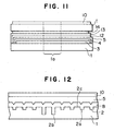
- FIG. 1 is a schematic partial enlarged cross-sectional view of an optical information recording medium No. 1-1 of the present invention.
- FIG. 2 is a perspective view of the optical information recording medium No. 1-1 of the present invention.
- the optical information recording medium No. 1-1 comprises a transparent substrate 1 with a preformat pattern 2 including grooves and/or pits in a fine concave and convex form on one side thereof, an information recording layer 3 provided on the transparent substrate 1, which is formed by filling the grooves and/or pits in the preformat pattern 2 of the transparent substrate 1 with a recording material, a reflection layer 4 provided on the information recording layer 3, a protective layer 5 provided on the reflection layer 4, and a UV cured ink layer 10 comprising an ink component provided on the protective layer 5.
- the transparent substrate 1 there can be employed conventional transparent substrates such as (1) a transparent substrate made by molding a transparent resin material such as polycarbonate, polymethyl methacrylate, polymethyl pentene, or epoxy resin into a desired shape to form a molded resin substrate, and then transferring a desired preformat pattern to one side of the molded resin substrate, and (2) a transparent substrate made by providing a desired preformat pattern made of a transparent resin layer on one side of a transparent glass or a transparent ceramic plate,
- the transparent substrate 1 for a disk-shaped optical information recording medium (hereinafter referred to as an optical disk) is formed in the shape of a disk with a center hole la in a central portion thereof as shown in FIG. 2.
- the transparent substrate 1 can be made by any conventionally known method.
- the preformat pattern 2 is constructed so as to include a beam guide portion in order to have at least a recording and reproducing laser beam follow a recording track.
- the beam guide portion is formed so as to include a guide groove 2a which is concentric with the center hole 1a or concentrically spiral around the center hole la.
- Prepits 2b such as address pits and clock pits are also formed along the guide groove 2a.
- the guide groove 2a and the prepits 2b are respectively formed with a different depth as shown in FIG. 1 in order to optically distinguish the guide groove 2a and the prepits 2b.
- the prepits 2b are formed between the adjoining guide grooves 2a, they can be formed with the same depth.
- wobble pits can be formed along the recording track instead of the guide groove 2a.
- the beam guide portion can be formed of the guide groove only, without the prepits 2b.
- the information recording layer 3 can be formed by filling the above-mentioned preformat pattern 2 with a recording material capable of absorbing light energy and converting the absorbed light energy into thermal energy, that is, a material with a light-to-heat conversion property, or a heat-mode recording material including at least an ionic dye material having such a light-to-heat conversion property.
- a recording material capable of absorbing light energy and converting the absorbed light energy into thermal energy that is, a material with a light-to-heat conversion property, or a heat-mode recording material including at least an ionic dye material having such a light-to-heat conversion property.
- Examples of such dye materials by which the information recording layer 3 can be formed are polymethine dye, anthraquinone dye, cyanine dye, phthalocyanine dye, naphthalocyanine dye, xantene dye, triphenylmethane dye, pyrylium dye, azulene dye, metal-containing azo dye, and azo dye.
- dicarbocyanine derivative, phthalocyanine derivative, naphalocyanine derivative, cyanine derivative and azo dye derivative are particularly preferable for use in the present invention.
- dye materials to which a variety of quenchers, such as aminium dye, are added can also be employed.
- a material composed of a resin in which at least one of the above-mentioned dye materials is dispersed can also be used as a material for forming the information recording layer 3.
- resins in which the above-mentioned dye materials can be dispersed are acrylic resin, vinyl resin, phenolic resin, fluoroplastics, silicone resin, polyamide resin, and cellulose resin.
- the information recording layer 3 can be formed by spin coating of a solution of any of the above exemplified dye materials in a solvent on a preformat pattern formation surface of the transparent substrate 1.
- the dye material which adheres to the land portions 2c between the guide grooves in the preformat patterns 2 is selectively removed, and the surface of the transparent substrate 1 is exposed, so that only the grooves in the preformat patterns 2 are filled with the dye material.
- the solvent for the dye material for example, an alcohol-based solvent, and a cellosolve-based solvent can be employed.
- the information recording layer 3 can further contain a chelate material which can assume a bidentate ligand as shown below.
- a chelate material are inorganic acids, dicarboxylic acid, oxycarboxylic acid, dioxy compound, oxyoximes, oxyaldehyde and derivatives thereof, diketones and the like, oxyquinones, tolopolones, N-oxide compound, aminocarboxylic acid and the like, hydroxylamines, oxines, aldimines, oxyazo compound, nitrosonaphtols, triazenes, biurets, formazans and dithizones, biguanide, glyoximes, diamines and the like, hydrazine derivatives, and thioethers.
- Derivatives including imino group can also be used in the information recording layer 3.
- phase-change materials which are capable of recording information by changing the arrangement of atoms therein, such as an alloy represented by a general formula of: A-B-C-Ge-Te, wherein A is at least one element selected from the group consisting of Cu, Ag, Au, Sc, Y, Ti, Zr, V, Nb, Cr, Mo, Mn, Fe, Ru, Co, Rh, Ni, Pd, Hf, Ta, W, Ir, Pt, Hg, B, C, N, P, O, S, Se, Lanthanide elements, Actinide element, alkaline earth metal elements, and inert gas elements; B is at least one element selected from the group consisting of T1, a halogen element such as I, and alkaline metal element such as Na; and C is at least one element selected from the group consisting of Sb, Sn, As, Pb, Bi, Zn, Cd, Si, Al, Ga and In
- Alloy materials used in magneto-optical recording materials for example, alloy materials composed of the above-mentioned metal elements such as Tb, Fe and Co, can also be employed as the material for the information recording layer 3.
- the material for use in the reflection layer 4 there is no particular restriction on the material for use in the reflection layer 4.
- Metallic materials such as Al, Ag, and Co, alloys comprising as the main component the above-mentioned metals, and dyes such as cyanine dye can be used for the reflection layer 4.
- Au and Au-containing alloys comprising as the main component therefor are preferable for use in the reflection layer 4. It is preferable that the content of Au in the above-mentioned Au-containing alloys be 80 to 100 atomic %, more preferably 90 to 100 atomic %.
- Aluminum can also be used in the reflection layer 4 since it is inexpensive and provides satisfactory results as a light reflection material when used in compact disks.
- the reflection layer 4 can be formed by vacuum film formation method, such as sputtering or vacuum deposition.
- vacuum film formation method such as sputtering or vacuum deposition.
- the protective layer 5 can be made of an inorganic material such as SiO, SiN, AlN, or an organic material such as a photo-setting resin.
- An inorganic protective layer can be formed by the vacuum film formation method.
- An organic protective layer can be made of a photo-setting resin film, for example, by spin coating SD1700, SD318, or SD301, made by Dainippon Ink & Chemicals, Incorporated, on the reflection layer 4, and irradiating the photo-setting resin film with resin curing rays.
- the thus formed protective layer 5 has a thickness of 10 ⁇ m or less, with a deposition amount of 0.0015 g/cm 2 or less.
- the information recording layer 3 was formed on a polycarbonate substrate with preformat patterns as shown in FIG. 1 and FIG. 2, by conducting spin coating of a solution of phthalocyanine.
- a metal film with a thickness of 100 nm was deposited by sputtering, whereby the reflection layer 4 was formed.
- a protective layer 5 was formed on the reflection layer 4 by providing a 5 ⁇ m thick film of a photo-setting resin (Trademark "SD1700” made by Dainippon Ink & Chemicals, Incorporated) with a thermal conductivity of 1.0 or less.
- a photo-setting resin (Trademark "SD1700” made by Dainippon Ink & Chemicals, Incorporated) with a thermal conductivity of 1.0 or less.
- the UV cured ink layer 10 was formed by depositing a DIC UV ink (made by Dainippon Ink & Chemicals, Incorporated) with a deposition amount of 0.002 g/cm 2 , whereby the optical information recording medium No. 1-1 of the present invention in the form of a disk was prepared.
- a DIC UV ink made by Dainippon Ink & Chemicals, Incorporated
- the amplitude attenuation time and the vibration frequency attenuation time of the optical information recording medium No. 1-1 of the present invention were measured.
- the amplitude attenuation time and the vibration frequency attenuation time of the optical information recording medium No. 1-1 were measured as follows:
- One peripheral portion of the thus prepared optical information recording medium No. 1-1 at a distance of 1.5 cm from the periphery thereof toward the center thereof was fixed, and another peripheral portion of the optical information recording medium on the opposite side of the fixed peripheral portion was vibrated in the direction perpendicular to the flat surface of the substrate of the optical information recording medium No. 1-1 at a vibration frequency of 10 per second.
- the amplitude attenuation time was measured by measuring a period of time required for a maximum amplitude of the vibrations of the recording medium 100 ms after the recording medium was vibrated as mentioned above to reduce to 10% of the maximum amplitude.
- the vibration frequency attenuation time was measured by measuring a period of time required for the total number of the vibrations of the recording medium in a period of time of 100 ms through 200 ms after the recording medium was vibrated as mentioned above to reduce to 90% of the total number of the above-mentioned vibrations.
- the results are shown in TABLE 1.
- Optical information recording media No. 1-2 to No. 1-11 of the present invention and comparative information recording media Nos. 1-1 and 1-2 were prepared in the same manner as that for the optical information recording medium No. 1-1 of the present invention in Example 1-1 except that the deposition amount of the UV cured ink layer 10 was changed as shown in the column of "Deposition amount of UV cured ink layer" in TABLE 1.
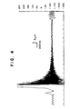
- FIG. 4 shows a representative example of the vibrations.
- TABLE 1 shows the changes in the amplitude attenuation time and the vibration frequency attenuation time of the optical information recording media in accordance with the changes in the deposition amount of the UV cured ink layer 10.
- TABLE 1 Examples Deposition amount of UV cured ink layer (g/cm 2 ) Amplitude attenuation time (ms) Vibration frequency attenuation time (ms) Comp. Ex.1 0 1500 5000 ⁇ Comp. Ex.2 0.001 1150 4500 Ex. 1-1 0.002 1000 3000 Ex. 1-2 0.003 580 820 Ex. 1-3 0.004 550 720 Ex. 1-4 0.005 300 300 Ex. 1-5 0.010 270 270 Ex. 1-6 0.020 270 270 Ex. 1-7 0.030 280 250 Ex. 1-8 0.040 200 150 Ex. 1-9 0.050 140 80 Ex. 1-10 0.060 90 80 Ex. 1-11 0.070 80 60
- the deposition amount of the UV cured ink layer 10 was 0.040 g/cm 2 or more, the load applied by the optical information recording medium disk to a motor for rotating the medium disk was so large that the UV cured ink layer worked so as to tend to cause the tone quality to deteriorate.
- the deposition amount of the UV cured ink layer 10 was in the range of 0.030 g/cm 2 to less than 0.040 g/cm 2 , the noise with a frequency of 10 Hz to 100 Hz was mainly attenuated in a short time, so that the tone quality was good.
- the deposition amount of the UV cured ink layer 10 was in the range of 0.010 g/cm 2 to less than 0.030 g/cm 2 , the noise with a frequency of about 10 Hz to 1000 Hz disappeared in a relatively short time, so that the tone quality was improved.
- the deposition amount of the UV cured ink layer 10 was in the range of 0.003 g/cm 2 to less than 0.010 g/cm 2 , the noise with a frequency of about 1000 Hz, which can be most sensitively recognized by the human ears, was effectively removed, so that the tone quality was best.
- the deposition amount of the Uv cured ink layer 10 was in the range of 0.002 g/cm 2 to less than 0.003 g/cm 2 , it took a time to remove noise. However, the tone quality was good.
- the transparent substrate can be produced by injection molding.
- the transparent substrate is produced by injection molding, it is preferable that the substrate be cooled with a cooling time of 5 seconds or more after it is injected from the mold thereof, since by such injection molding, the fluctuations in the direction of the axis of rotation of the substrate, that is, in the direction perpendicular to the flat surface of the recording medium, and any in-plane distortion can be avoided so that the generation of noise can be effectively reduced.
- the evaluation as to the generation of noise of the optical information recording media was conducted by an organoleptic test by experts' actually listening to music reproduced by each recording medium.
- the degree of the shrinkage of the UV cured resin used in the UV cured ink layer 10 has an effect on the amplitude attenuation time and the vibration frequency attenuation time mentioned above. It is preferable to use a UV cured resin with a small shrinkage for use in the UV cured ink layer 10.
- FIG. 5 is a schematic partial enlarged cross-sectional view of a main portion of the optical information recording medium No, 2.
- the optical information recording medium No. 2 was prepared in the same manner as the optical information recording medium No. 1-1 prepared in Example 1-1 except that a hydrophilic-material-containing layer 15 comprising a hydrophilic material was overlaid on the UV cured ink layer 10.
- hydrophilic material for use in the layer 15 for example, polyvinyl pyrrolidone and polyvinyl alcohol can be employed.
- the hydrophilic-material-containing layer 15 may also contain an extender pigment in addition to the hydrophilic material.
- the total weight of the UV cured ink layer 10 and the hydrophilic-material-containing layer 15 was adjusted to the same deposition amount of the UV cured ink layer 10 as in Examples 1-1 to 1-11, whereby optical information recording media Nos. 2-1 to 2-11 were prepared, which are collectively referred to as the optical information recording medium No. 2.
- the tone characteristics of the optical information recording medium No. 2 exhibited the same tendency as those of the optical information recording media Nos. 1-1 to 1-11.
- the UV cured ink layer 10 and the hydrophilic-material-containing layer 15 can be formed individually or in combination so as to cover not only the outer ring-shaped portion comprising the recording layer, but also the inner ring-shaped portion corresponding to a clamping area for the optical information recording medium No. 2, whereby the leakage of a laser beam from inside a recording and reproducing apparatus can be completely cut.
- the leakage of the laser beam can be cut, not only by shielding the inner ring-shaped portion corresponding to the clamping area for the optical information recording medium No. 2 with a colored layer as mentioned above, but also by roughening the surface of the inner ring-shaped portion so as to have a light transparency of 92% or less, whereby the tone quality can be significantly improved.
- the UV cured ink layers 10 or the hydrophilic-material-containing layers 15, for instance, with a deposition amount of 0.0065 g/cm 2 can be formed, for instance, by coating with a deposition amount of 0.0013 g/cm 2 , followed by curing the coated layer, and again coating the cured layer with a deposition amount of 0.0013 g/cm 2 , and curing the coated layer. A series of these steps are repeated until the total deposition amount amounts to 0.0065 g/cm 2 .
- the deposition amount for the first coating is more than 0.0040 g/cm 2 , it takes a long period of time for the curing the coated layer, so that the productivity is lowered.
- a UV coating material be coated in an amount of 0.0040 g/cm 2 or less at each coating thereof, followed by curing thereof.
- the deposition amount for each coating can be more than 0.0040 g/cm 2 .
- FIG. 6 is a schematic partial enlarged cross-sectional view of a main portion of the optical information recording medium No. 3.
- the optical recording medium No. 3 comprises a transparent substrate 1 with a preformat pattern formation surface on one side thereof, an undercoat layer 6 which is formed on the side of the preformat pattern formation surface of the transparent substrate 1, thereby forming a preformat pattern 2 on the undercoat layer 6, an information recording layer 3 formed on the undercoat layer 6 with the grooves of the preformat pattern 2 being filled with a recording material comprising a dye material, a reflection layer 4 formed on the information recording layer 3, a protective layer 5 coated on the reflection layer 4, and a UV cured ink layer 10 formed on the protective layer 4,
- optical information recording medium No. 3 The transparent substrate 1, the information recording layer 3, the reflection layer 4, the protective layer 5 and the UV cured ink layer 10 in the above optical recording medium No. 3 are respectively the same as those in the optical recording medium No. 1 in Example 1, whereby optical information recording media Nos. 3-1 to 3-11 were prepared, which are collectively referred to as optical information recording medium No. 3.
- the undercoat layer 6 is provided to improve the adhesion between the transparent substrate 1 and the information recording layer 3 and also to improve the recording sensitivity of the recording medium.
- the undercoat layer 6 serves to protect the information recording layer 3.
- the undercoat layer 6 can be made of, for example, a hydrophilic resin such as polyvinyl alcohol, polyethylene oxide, polyacrylic acid, sodium polystyrenesulfonate, polyvinyl pyrrolidone, polymethacrylic acid, polypropylenen glycol, methyl cellulose, polyvinyl nitrate, and nitro cellulose.
- a hydrophilic resin such as polyvinyl alcohol, polyethylene oxide, polyacrylic acid, sodium polystyrenesulfonate, polyvinyl pyrrolidone, polymethacrylic acid, polypropylenen glycol, methyl cellulose, polyvinyl nitrate, and nitro cellulose.
- the undercoat layer 6 can be formed by conducting spin coating, using an aqueous solution of any of the above-mentioned hydrophilic resins, on the preformat pattern formation surface of the transparent substrate 1.
- the undercoat layer 6 is made of the hydrophilic resin, the water resistance including moisture resistance and moisture penetration resistance, and the heat resistance thereof are poor, so that it is preferable that the water resistance and the heat resistance of the undercoat layer 6 be improved by subjecting the undercoat layer 6 to cross-linking treatment and crystallization treatment. More specifically, in this case, it is preferable that the undercoat layer 6 be formed, using an aqueous solution of the hydrophilic resin with the addition of a cross-linking agent thereto, and a cross-linking reaction be caused to take place in the undercoat layer 6 with light irradiation or with the application of heat to the undercoat layer 6.
- an undercoat layer 6 free of cross-linking agent is subjected to heat treatment to crystallize the undercoat layer 6.
- PVA polvinyl alcohol
- the cross-linking treatment is considered to be better than the crystallization treatment, since the cross-linking treatment has no adverse thermal effects on the transparent substrate 1, and the operating efficiency thereof is better than that of the crystallization treatment.
- the hydrophilic resin for the undercoat layer 6 polyvinyl alcohol was employed, and the undercoat layer 6 was formed by spin coating, using a 2.0 wt.% aqueous solution of polyvinyl alcohol and chromium as the cross-linking agent.
- optical information recording medium No. 3 of the present invention was prepared.
- the tone characteristics of the optical information recording medium No. 3 exhibited the same tendency as those of the optical information recording media Nos. 1-1 to 1-11.
- FIG. 7 is a schematic partial enlarged cross-sectional view of a main portion of the optical information recording medium No. 4.
- the optical recording medium No. 4 comprises a transparent substrate 1 with a preformat pattern 2 on one side thereof, an information recording layer 3 which is formed by filling the grooves of the preformat pattern 2 of the transparent substrate 1 with a recording material comprising a dye, an intermediate layer 7 formed on the information recording layer 3, a reflection layer 4, a protective layer 5 formed on the reflection layer 4, and a UV cured ink layer 10 formed on the protective layer 5.
- the transparent substrate 1, the information recording layer 3, the reflection layer 4, the protective layer 5 and the UV cured ink layer 10 in the above optical recording medium No. 4 are respectively the same as those in the optical recording media Nos. 1-1 to 1-11 in Examples 1-1 to 1-11, whereby optical information recording media Nos. 4-1 to 4-11 were prepared, which are collectively referred to as the optical information recording medium No. 4.
- the tone characteristics of the optical information recording medium No. 4 exhibited the same tendency as those of the optical information recording media Nos. 1-1 to 1-11,
- the intermediate layer 7 is provided to improve the adhesion between the information recording layer 3 and the reflection layer 4 and also to improve the recording sensitivity of the optical information recording medium No. 4.
- the intermediate layer 7 is also provided to protect the information recording layer 3 and can comprise a hydrophilic resin of the same kind as that of the hydrophilic resin employed in the undercoat layer 6 of the optical information recording media No. 3 in Example 3, or an electron-donating or electron-accepting material for a redox reaction of a metallic reflection film.
- the intermediate layer 7 can be formed by spin coating of an aqueous solution of the hydrophilic resin on the information recording layer 3.
- the intermediate layer 7 formed by the spin coating be subjected to the cross-linking treatment or the crystallization treatment mentioned in Example 3 in order to improve the water resistance and the heat resistance of the intermediate layer 7.
- FIG. 8 is a perspective view of an optical information recording medium No. 5 of the present invention, which is a so-called partial ROM type optical information recording medium comprising an information recording area 11.
- the information recording area 11 includes a ROM area 11a and a write-once-read-many area 11b which is hereinafter referred to as WORM area 11b.
- beam guide portions, header portions, and read-only information signals are formed in the form of prepits as preformat pattern 2 (not shown).
- WORM area 11b only beam guide portion and header portions are formed as preformat pattern 2 (not shown). Unrecorded portions between the header portions which are arranged at predetermined constant intervals on a track constitute write-once-read-many areas for information.
- the WORM area 11b can be formed in the same manner as in the optical information recording medium No. 1 prepared in Example 1, or in the optical information recording medium No. 2 prepared in Example 2, or in the optical information recording medium No. 3 prepared in Example 3.
- the transparent substrate 1, the information recording layer 3, the reflection layer 4, the protective layer 5 and the UV cured ink layer 10 in the above optical information recording medium No. 5 are respectively the same as those in the above-mentioned optical recording media Nos. 1 to 3 prepared in Examples 1 to 3.
- a printed layer (not shown) can also be formed on the external surface of the optical information recording medium No. 5.
- the WORM area 11b exhibited the same excellent recording and reproduction characteristics as those of the above-mentioned optical information recording media.
- the ROM area 11a exhibited excellent reproduction characteristics when reproduction was carried out, using a drive apparatus made in accordance with the CD or DVD standards.
- FIG. 9 is a flow chart indicating the steps of producing the disk-shaped optical information recording medium of the present invention.
- the steps S7 and S8 can be conducted at the same time.
- the shape of the grooves can be made neat by heating the grooves at 90°C to 180°C for 5 to 90 minutes.
- FIG. 10 is a flow chart describing the details of the steps for forming the recording layer and an intermediate layer in the flow chart in FIG. 9.
- FIG. 11 is a schematic partial enlarged cross-sectional view of the optical information recording medium No. 6.
- the optical information recording medium No. 6 is such a structure that two substrates 1 are stuck together.
- an adhesive layer 12 is overlaid on the protective layer 5.
- a second substrate 1' is overlaid on the protective layer 12 through a first intermediate layer 13 and a second intermediate layer 14.
- the water-soluble resin used in the above-mentioned undercoat layer and intermediate layer, and the metallic material used in the above-mentioned reflection layer can also be used in the above-mentioned first intermediate layer 13 and second intermediate layer 14.
- the UV cured ink layer 10 was overlaid with the same deposition amount as in Examples 1-1 to 1-11, whereby the optical information recording media No. 6-1 to 6-11 of the present invention were prepared.
- the optical information recording media No. 6-1 to 6-11 are collectively referred to as the optical information recording medium No. 6.
- the recording and reproduction characteristics of the optical information recording medium No. 6 were the same as those of the optical information recording media No. 1-1 to No. 1-11 prepared in Examples 1-1 to 1-11.
- Example 1-1 The procedure of preparing the optical information recording medium No. 1-1 in Example 1-1 was repeated except that the deposition amount of the UV cured ink layer 10 was changed from 0.002 g/cm 2 to 0.0067 g/cm 2 , whereby an optical information recording medium No. 7 of the present invention was prepared.
- optical information recording medium No. 7 were formed information recording, reproducing and/or deleting tracks along which tracks information can be recorded, reproduced and/or deleted by an information recording, with an average distance between the adjoining tracks measured in the direction perpendicular to the extending direction of the tracks being 1.6 ⁇ m.
- a tracing device for tracing an information recording, reproducing or deleting position in the track
- an in-plane deviation of a pick-up device is monitored, and from the monitored in-plane deviation, a correct recording, reproducing or deleting position was virtually determined, whereby a maximum in-plane deviation of the recording, reproducing or deleting position was determined.
- the result was that the radial run-out (O-P) of the samples was in the range of 4 ⁇ m to 30 ⁇ m as designed.
- the accelerations of the samples in the radial direction varied in the range of 0.045 m/s 2 to 0.358 m/s 2 .
- Audio information was recorded in these samples by use of CD W900E made by Sony Corp.
- the tone quality of each sample was evaluated by 4 experts in this field. The result was that excellent tone quality was obtained when the radial run-out was 20 ⁇ m or less, and the acceleration of the in-plane deviation was 0.25 m/s 2 or less as shown in FIG. 3.
- FIG. 12 is a schematic partial enlarged cross-sectional view of a main portion of the optical information recording medium No. 8.
- the optical information recording medium No. 8 was prepared in the same manner as the optical information recording medium No. 1-1 prepared in Example 1-1 except that the information recording layer 3 and the reflection layer 4 were replaced by a metallic layer 8 made of aluminum which was formed on the preformat pattern of the transparent substrate 1, whereby optical information recording media Nos. 8-1 to 8-11 were prepared, which are collectively referred to as the optical information recording medium No. 6.
- the metallic layer 8 can also be formed by the same film formation method as that for the formation of the reflection layer 4.
- the tone characteristics of the optical information recording medium No. 8 exhibited the same tendency as those of the optical information recording media Nos. 1-1 to 1-11.
- optical information recording media Nos. 1-1 to No. 8 respectively prepared in Examples 1-1 to 8 are all disk-shaped.
- the present invention is not limited to such disk-shaped optical information recording media, but may be card-shaped, stick-shaped, tape-shaped, or in other shapes.
- the vibrations in the in-plane direction of the recording medium and the eccentricity of the recording medium can also be reduced and therefore noise generated by such vibrations and the eccentricity can be effectively reduced.
Landscapes
- Engineering & Computer Science (AREA)
- Manufacturing & Machinery (AREA)
- Optical Record Carriers And Manufacture Thereof (AREA)
Applications Claiming Priority (2)
| Application Number | Priority Date | Filing Date | Title |
|---|---|---|---|
| JP23409599 | 1999-08-20 | ||
| EP00307156A EP1079380A3 (fr) | 1999-08-20 | 2000-08-21 | Support d'enregistrement optique |
Related Parent Applications (1)
| Application Number | Title | Priority Date | Filing Date |
|---|---|---|---|
| EP00307156A Division EP1079380A3 (fr) | 1999-08-20 | 2000-08-21 | Support d'enregistrement optique |
Publications (2)
| Publication Number | Publication Date |
|---|---|
| EP1898405A2 true EP1898405A2 (fr) | 2008-03-12 |
| EP1898405A3 EP1898405A3 (fr) | 2008-12-31 |
Family
ID=16965553
Family Applications (2)
| Application Number | Title | Priority Date | Filing Date |
|---|---|---|---|
| EP07075821A Withdrawn EP1898405A3 (fr) | 1999-08-20 | 2000-08-21 | Support d'enregistrement d'informations |
| EP00307156A Withdrawn EP1079380A3 (fr) | 1999-08-20 | 2000-08-21 | Support d'enregistrement optique |
Family Applications After (1)
| Application Number | Title | Priority Date | Filing Date |
|---|---|---|---|
| EP00307156A Withdrawn EP1079380A3 (fr) | 1999-08-20 | 2000-08-21 | Support d'enregistrement optique |
Country Status (2)
| Country | Link |
|---|---|
| US (2) | US20020182365A1 (fr) |
| EP (2) | EP1898405A3 (fr) |
Families Citing this family (5)
| Publication number | Priority date | Publication date | Assignee | Title |
|---|---|---|---|---|
| US6562432B2 (en) | 2000-09-29 | 2003-05-13 | Ricoh Company, Ltd. | Optical recording medium and method of manufacturing the optical recording medium |
| US20020170897A1 (en) * | 2001-05-21 | 2002-11-21 | Hall Frank L. | Methods for preparing ball grid array substrates via use of a laser |
| US7407696B2 (en) * | 2003-01-24 | 2008-08-05 | Board Of Trustees Operating Michigan State University | Phase change materials for storage media |
| EP1475793B1 (fr) * | 2003-04-15 | 2007-12-05 | Ricoh Company, Ltd. | Support d'enregistrement optique à écriture unique et à lecture multiple et procédé d'écriture et de lecture du support d'enregistrement optique |
| WO2007056074A2 (fr) * | 2005-11-03 | 2007-05-18 | Princo America Corp. | Disque optique et procede de fabrication de celui-ci |
Family Cites Families (11)
| Publication number | Priority date | Publication date | Assignee | Title |
|---|---|---|---|---|
| NL8501148A (nl) * | 1985-04-19 | 1986-11-17 | Optical Storage Int | Werkwijze voor het aanbrengen van een optisch detecteerbare structuur op het substraat van een optisch uitleesbare informatieschijf, matrijs ten behoeve van de werkwijze, inrichting voor het uitvoeren van de werkwijze, alsmede informatieschijf vervaardigd volgens de werkwijze. |
| JPH0298848A (ja) * | 1988-10-04 | 1990-04-11 | Fuji Photo Film Co Ltd | 情報記録媒体の製造方法 |
| EP0373763B1 (fr) * | 1988-12-12 | 1996-01-03 | John P. Murphy | Reproduction pour CD |
| JPH0660589A (ja) * | 1992-08-07 | 1994-03-04 | Hitachi Cable Ltd | Cdスタビライザ |
| KR0185765B1 (ko) * | 1993-04-10 | 1999-04-15 | 가와다 미쓰구 | 광 정보매체와 그 제조방법 |
| JP3364336B2 (ja) * | 1994-09-08 | 2003-01-08 | ティーディーケイ株式会社 | 光ディスクおよび被記録材 |
| JPH08241540A (ja) * | 1995-03-03 | 1996-09-17 | Matsushita Electric Ind Co Ltd | 光ディスクおよびその製造方法 |
| JPH08212595A (ja) * | 1995-11-13 | 1996-08-20 | Toshiba Corp | 光学式ディスクレコ−ド |
| TW442779B (en) * | 1998-08-31 | 2001-06-23 | Sony Corp | Cartridge for recording medium |
| JP2000357345A (ja) * | 1999-06-11 | 2000-12-26 | Sony Corp | 光記録媒体 |
| DE60031604T2 (de) * | 1999-07-13 | 2007-09-13 | Fuji Photo Film Co., Ltd., Minami-Ashigara | Medium für optische Aufzeichnung |
-
2000
- 2000-08-21 EP EP07075821A patent/EP1898405A3/fr not_active Withdrawn
- 2000-08-21 EP EP00307156A patent/EP1079380A3/fr not_active Withdrawn
-
2002
- 2002-06-18 US US10/174,207 patent/US20020182365A1/en not_active Abandoned
-
2003
- 2003-05-20 US US10/442,029 patent/US6866910B2/en not_active Expired - Fee Related
Also Published As
| Publication number | Publication date |
|---|---|
| EP1079380A2 (fr) | 2001-02-28 |
| US20030224136A1 (en) | 2003-12-04 |
| EP1898405A3 (fr) | 2008-12-31 |
| US6866910B2 (en) | 2005-03-15 |
| EP1079380A3 (fr) | 2004-03-31 |
| US20020182365A1 (en) | 2002-12-05 |
Similar Documents
| Publication | Publication Date | Title |
|---|---|---|
| JP4111666B2 (ja) | 光情報記録媒体の製造方法 | |
| EP0514799B1 (fr) | Procédé de fabrication d'un milieu d'enregistrement optique | |
| JPH0827983B2 (ja) | 光情報記録媒体 | |
| EP1069556A1 (fr) | Matériau pour enregistrement optique | |
| EP0518213B1 (fr) | Support d'enregistrement optique | |
| US5244774A (en) | Optical information recording medium | |
| US6866910B2 (en) | Information recording medium | |
| JP2668604B2 (ja) | 光情報記録方法 | |
| JP2514846B2 (ja) | 光情報記録方法及び情報記録媒体 | |
| JP3773627B2 (ja) | 情報記録媒体 | |
| EP1811516A1 (fr) | Support d enregistrement d informations optiques et méthode pour fabriquer celui-ci | |
| JP2529133B2 (ja) | 情報記録媒体 | |
| JP3246690B2 (ja) | 光記録方法 | |
| JP2512044B2 (ja) | 光記録媒体及び光記録方法 | |
| JP2001134982A (ja) | 情報記録媒体 | |
| JP2671141B2 (ja) | 情報記録媒体およびその製造方法 | |
| JP2663009B2 (ja) | 情報記録媒体およびその製造方法 | |
| JP3073266B2 (ja) | 光記録媒体の製造方法 | |
| JP2747744B2 (ja) | 光情報記録方法 | |
| JPH03120635A (ja) | 再生用情報記録媒体およびその製造方法 | |
| JP2007052919A (ja) | 情報記録媒体 | |
| JP3896402B2 (ja) | 光情報記録媒体の製造方法及び光情報記録媒体 | |
| JPH04337534A (ja) | 光記録媒体 | |
| JP3718076B2 (ja) | 光情報記録媒体 | |
| JP2793516B2 (ja) | 光情報記録媒体とその再生方法 |
Legal Events
| Date | Code | Title | Description |
|---|---|---|---|
| PUAI | Public reference made under article 153(3) epc to a published international application that has entered the european phase |
Free format text: ORIGINAL CODE: 0009012 |
|
| 17P | Request for examination filed |
Effective date: 20071001 |
|
| AC | Divisional application: reference to earlier application |
Ref document number: 1079380 Country of ref document: EP Kind code of ref document: P |
|
| AK | Designated contracting states |
Kind code of ref document: A2 Designated state(s): DE ES FR GB IT NL |
|
| AX | Request for extension of the european patent |
Extension state: AL LT LV MK RO SI |
|
| PUAL | Search report despatched |
Free format text: ORIGINAL CODE: 0009013 |
|
| AK | Designated contracting states |
Kind code of ref document: A3 Designated state(s): DE ES FR GB IT NL |
|
| AX | Request for extension of the european patent |
Extension state: AL LT LV MK RO SI |
|
| RIC1 | Information provided on ipc code assigned before grant |
Ipc: G11B 7/24 20060101AFI20080201BHEP |
|
| AKX | Designation fees paid |
Designated state(s): DE ES FR GB IT NL |
|
| STAA | Information on the status of an ep patent application or granted ep patent |
Free format text: STATUS: THE APPLICATION HAS BEEN WITHDRAWN |
|
| 18W | Application withdrawn |
Effective date: 20091231 |