EP1899191B1 - Kombiinstrument für ein kraftfahrzeug - Google Patents
Kombiinstrument für ein kraftfahrzeug Download PDFInfo
- Publication number
- EP1899191B1 EP1899191B1 EP06742624A EP06742624A EP1899191B1 EP 1899191 B1 EP1899191 B1 EP 1899191B1 EP 06742624 A EP06742624 A EP 06742624A EP 06742624 A EP06742624 A EP 06742624A EP 1899191 B1 EP1899191 B1 EP 1899191B1
- Authority
- EP
- European Patent Office
- Prior art keywords
- display device
- motor vehicle
- display
- combination instrument
- semi
- Prior art date
- Legal status (The legal status is an assumption and is not a legal conclusion. Google has not performed a legal analysis and makes no representation as to the accuracy of the status listed.)
- Expired - Lifetime
Links
Images

Classifications
-
- B—PERFORMING OPERATIONS; TRANSPORTING
- B60—VEHICLES IN GENERAL
- B60K—ARRANGEMENT OR MOUNTING OF PROPULSION UNITS OR OF TRANSMISSIONS IN VEHICLES; ARRANGEMENT OR MOUNTING OF PLURAL DIVERSE PRIME-MOVERS IN VEHICLES; AUXILIARY DRIVES FOR VEHICLES; INSTRUMENTATION OR DASHBOARDS FOR VEHICLES; ARRANGEMENTS IN CONNECTION WITH COOLING, AIR INTAKE, GAS EXHAUST OR FUEL SUPPLY OF PROPULSION UNITS IN VEHICLES
- B60K35/00—Instruments specially adapted for vehicles; Arrangement of instruments in or on vehicles
- B60K35/20—Output arrangements, i.e. from vehicle to user, associated with vehicle functions or specially adapted therefor
- B60K35/21—Output arrangements, i.e. from vehicle to user, associated with vehicle functions or specially adapted therefor using visual output, e.g. blinking lights or matrix displays
- B60K35/215—Output arrangements, i.e. from vehicle to user, associated with vehicle functions or specially adapted therefor using visual output, e.g. blinking lights or matrix displays characterised by the combination of multiple visual outputs, e.g. combined instruments with analogue meters and additional displays
-
- B—PERFORMING OPERATIONS; TRANSPORTING
- B60—VEHICLES IN GENERAL
- B60K—ARRANGEMENT OR MOUNTING OF PROPULSION UNITS OR OF TRANSMISSIONS IN VEHICLES; ARRANGEMENT OR MOUNTING OF PLURAL DIVERSE PRIME-MOVERS IN VEHICLES; AUXILIARY DRIVES FOR VEHICLES; INSTRUMENTATION OR DASHBOARDS FOR VEHICLES; ARRANGEMENTS IN CONNECTION WITH COOLING, AIR INTAKE, GAS EXHAUST OR FUEL SUPPLY OF PROPULSION UNITS IN VEHICLES
- B60K35/00—Instruments specially adapted for vehicles; Arrangement of instruments in or on vehicles
- B60K35/20—Output arrangements, i.e. from vehicle to user, associated with vehicle functions or specially adapted therefor
- B60K35/21—Output arrangements, i.e. from vehicle to user, associated with vehicle functions or specially adapted therefor using visual output, e.g. blinking lights or matrix displays
- B60K35/213—Virtual instruments
-
- B—PERFORMING OPERATIONS; TRANSPORTING
- B60—VEHICLES IN GENERAL
- B60K—ARRANGEMENT OR MOUNTING OF PROPULSION UNITS OR OF TRANSMISSIONS IN VEHICLES; ARRANGEMENT OR MOUNTING OF PLURAL DIVERSE PRIME-MOVERS IN VEHICLES; AUXILIARY DRIVES FOR VEHICLES; INSTRUMENTATION OR DASHBOARDS FOR VEHICLES; ARRANGEMENTS IN CONNECTION WITH COOLING, AIR INTAKE, GAS EXHAUST OR FUEL SUPPLY OF PROPULSION UNITS IN VEHICLES
- B60K35/00—Instruments specially adapted for vehicles; Arrangement of instruments in or on vehicles
- B60K35/20—Output arrangements, i.e. from vehicle to user, associated with vehicle functions or specially adapted therefor
- B60K35/21—Output arrangements, i.e. from vehicle to user, associated with vehicle functions or specially adapted therefor using visual output, e.g. blinking lights or matrix displays
- B60K35/22—Display screens
-
- B—PERFORMING OPERATIONS; TRANSPORTING
- B60—VEHICLES IN GENERAL
- B60K—ARRANGEMENT OR MOUNTING OF PROPULSION UNITS OR OF TRANSMISSIONS IN VEHICLES; ARRANGEMENT OR MOUNTING OF PLURAL DIVERSE PRIME-MOVERS IN VEHICLES; AUXILIARY DRIVES FOR VEHICLES; INSTRUMENTATION OR DASHBOARDS FOR VEHICLES; ARRANGEMENTS IN CONNECTION WITH COOLING, AIR INTAKE, GAS EXHAUST OR FUEL SUPPLY OF PROPULSION UNITS IN VEHICLES
- B60K35/00—Instruments specially adapted for vehicles; Arrangement of instruments in or on vehicles
- B60K35/20—Output arrangements, i.e. from vehicle to user, associated with vehicle functions or specially adapted therefor
- B60K35/28—Output arrangements, i.e. from vehicle to user, associated with vehicle functions or specially adapted therefor characterised by the type of the output information, e.g. video entertainment or vehicle dynamics information; characterised by the purpose of the output information, e.g. for attracting the attention of the driver
-
- B—PERFORMING OPERATIONS; TRANSPORTING
- B60—VEHICLES IN GENERAL
- B60K—ARRANGEMENT OR MOUNTING OF PROPULSION UNITS OR OF TRANSMISSIONS IN VEHICLES; ARRANGEMENT OR MOUNTING OF PLURAL DIVERSE PRIME-MOVERS IN VEHICLES; AUXILIARY DRIVES FOR VEHICLES; INSTRUMENTATION OR DASHBOARDS FOR VEHICLES; ARRANGEMENTS IN CONNECTION WITH COOLING, AIR INTAKE, GAS EXHAUST OR FUEL SUPPLY OF PROPULSION UNITS IN VEHICLES
- B60K35/00—Instruments specially adapted for vehicles; Arrangement of instruments in or on vehicles
- B60K35/20—Output arrangements, i.e. from vehicle to user, associated with vehicle functions or specially adapted therefor
- B60K35/29—Instruments characterised by the way in which information is handled, e.g. showing information on plural displays or prioritising information according to driving conditions
-
- B—PERFORMING OPERATIONS; TRANSPORTING
- B60—VEHICLES IN GENERAL
- B60K—ARRANGEMENT OR MOUNTING OF PROPULSION UNITS OR OF TRANSMISSIONS IN VEHICLES; ARRANGEMENT OR MOUNTING OF PLURAL DIVERSE PRIME-MOVERS IN VEHICLES; AUXILIARY DRIVES FOR VEHICLES; INSTRUMENTATION OR DASHBOARDS FOR VEHICLES; ARRANGEMENTS IN CONNECTION WITH COOLING, AIR INTAKE, GAS EXHAUST OR FUEL SUPPLY OF PROPULSION UNITS IN VEHICLES
- B60K35/00—Instruments specially adapted for vehicles; Arrangement of instruments in or on vehicles
- B60K35/60—Instruments characterised by their location or relative disposition in or on vehicles
-
- B—PERFORMING OPERATIONS; TRANSPORTING
- B60—VEHICLES IN GENERAL
- B60K—ARRANGEMENT OR MOUNTING OF PROPULSION UNITS OR OF TRANSMISSIONS IN VEHICLES; ARRANGEMENT OR MOUNTING OF PLURAL DIVERSE PRIME-MOVERS IN VEHICLES; AUXILIARY DRIVES FOR VEHICLES; INSTRUMENTATION OR DASHBOARDS FOR VEHICLES; ARRANGEMENTS IN CONNECTION WITH COOLING, AIR INTAKE, GAS EXHAUST OR FUEL SUPPLY OF PROPULSION UNITS IN VEHICLES
- B60K35/00—Instruments specially adapted for vehicles; Arrangement of instruments in or on vehicles
- B60K35/80—Arrangements for controlling instruments
- B60K35/81—Arrangements for controlling instruments for controlling displays
-
- B—PERFORMING OPERATIONS; TRANSPORTING
- B60—VEHICLES IN GENERAL
- B60K—ARRANGEMENT OR MOUNTING OF PROPULSION UNITS OR OF TRANSMISSIONS IN VEHICLES; ARRANGEMENT OR MOUNTING OF PLURAL DIVERSE PRIME-MOVERS IN VEHICLES; AUXILIARY DRIVES FOR VEHICLES; INSTRUMENTATION OR DASHBOARDS FOR VEHICLES; ARRANGEMENTS IN CONNECTION WITH COOLING, AIR INTAKE, GAS EXHAUST OR FUEL SUPPLY OF PROPULSION UNITS IN VEHICLES
- B60K37/00—Dashboards
-
- B—PERFORMING OPERATIONS; TRANSPORTING
- B60—VEHICLES IN GENERAL
- B60K—ARRANGEMENT OR MOUNTING OF PROPULSION UNITS OR OF TRANSMISSIONS IN VEHICLES; ARRANGEMENT OR MOUNTING OF PLURAL DIVERSE PRIME-MOVERS IN VEHICLES; AUXILIARY DRIVES FOR VEHICLES; INSTRUMENTATION OR DASHBOARDS FOR VEHICLES; ARRANGEMENTS IN CONNECTION WITH COOLING, AIR INTAKE, GAS EXHAUST OR FUEL SUPPLY OF PROPULSION UNITS IN VEHICLES
- B60K2360/00—Indexing scheme associated with groups B60K35/00 or B60K37/00 relating to details of instruments or dashboards
- B60K2360/16—Type of output information
- B60K2360/179—Distances to obstacles or vehicles
-
- B—PERFORMING OPERATIONS; TRANSPORTING
- B60—VEHICLES IN GENERAL
- B60K—ARRANGEMENT OR MOUNTING OF PROPULSION UNITS OR OF TRANSMISSIONS IN VEHICLES; ARRANGEMENT OR MOUNTING OF PLURAL DIVERSE PRIME-MOVERS IN VEHICLES; AUXILIARY DRIVES FOR VEHICLES; INSTRUMENTATION OR DASHBOARDS FOR VEHICLES; ARRANGEMENTS IN CONNECTION WITH COOLING, AIR INTAKE, GAS EXHAUST OR FUEL SUPPLY OF PROPULSION UNITS IN VEHICLES
- B60K2360/00—Indexing scheme associated with groups B60K35/00 or B60K37/00 relating to details of instruments or dashboards
- B60K2360/20—Optical features of instruments
- B60K2360/27—Optical features of instruments using semi-transparent optical elements
Definitions
- the invention relates to an instrument cluster for a motor vehicle having a first display device and a second display device, wherein the combination instrument has a semitransparent mirror for reflecting light emitted by the second display device, and wherein the semitransparent mirror is substantially transparent to light emitted by the first display device is.
- the EP 0 648 639 discloses a display device having a first display and a second display.
- the second display is reflected on one of the first display upstream reflection surface, said reflection surface is variable in their optical transparency.
- the publication DE 43 23 082 C2 describes a display unit for motor vehicles with a first display element containing a first display level and designed as a transparent disc second display level on which information content of a second display element can be made visible.
- the second display plane can be formed, at least in a limited field, as a light-impermeable projection plane.
- the publication DE 103 33 745 A1 relates to a display device for a motor vehicle with a first display device which emits imaging light, and a second display device.
- the second display device is arranged at an angle to the first display device, wherein a mirror is provided therebetween, which is permeable to the imaging light of the first display device and reflective for the imaging light of the second display device.
- an instrument cluster with a base body which is divided into display panels, which are aligned at different angles to each other.
- On the front of the body is arranged over several display panels extending additional circuit board.
- This consists of rigid printed circuit board parts, which have flexible connection areas with interconnects in the transition region of the display panels.
- the integrated instrument cluster comprises a device for controlling the display instruments and performing one or more other functions of the body center electronics and body power electronics and at least one integrated device security device.
- an instrument cluster for displaying different measurement data in a motor vehicle which is equipped with analog and digital gauges, wherein mechanical, optical and electrical components of the gauges are mounted on a circuit board device and the electronic control of the gauges from an attachable on the circuit board device electronics module he follows.
- the circuit board device has a wiring film which can be clamped between a back cover and a front cover.
- an instrument cluster for a motor vehicle having the features of claim 1, wherein the second display device by means of the disc with adjustable transparency optionally (completely or partially) can be covered.
- the pane with adjustable transparency comprises at least one twisted nematics layer, at least one CLC (cholesteric liquid crystal) layer, at least one PDLC (polymer dispersed liquid crystal) layer and / or at least one PALC layer.
- Twisted Nematics layers can be found on the website www.toshiba.ca/web/pdf/Innovative display Toshiba final.pdf and on the website www.tvtechnology.com/features/Tech-Corner/f_AdvancedDisplays-03.10.04.shtml.
- PALC layers are in the US 6,674,419 and the US Pat. No. 6,597,412 disclosed.
- the first display device is configured as a digital display or comprises a digital display.
- the first display device can, for example, according to the in the EP 0 482 805 A1 designated by the reference numeral 12 second image source be configured.
- the second display device is designed as an analog display or comprises an analog display.
- the semitransparent mirror, the first display device and the second display device are advantageously arranged relative to one another in such a way that a mirror image of the second display device for a viewer appears in front of the first display device.
- a semitransparent mirror in the sense of the invention comprises in particular one in the EP 0 482 805 A1 denoted by reference numeral 13 combiner.
- the aforementioned object is also achieved by a motor vehicle with a one or more of the aforementioned features comprehensive instrument cluster.
- the motor vehicle comprises in an advantageous embodiment of the invention, a display control associated with the instrument cluster for adjusting the transparency of the disc with adjustable transparency as a function of information displayed by means of the first display device.
- a slice with adjustable transparency in the sense of the invention is a slice which, depending on an applied voltage, in particular by an orthogonal polarization of light, can assume a state in which it is transparent and can assume a state in which it is opaque is.
- a slice with adjustable transparency in the sense of the invention is a slice that can assume a state in which it is transparent and can assume a state in which it is opaque, with advantageously less than 0.1 s between these two states can be switched.
- Motor vehicle in the sense of the invention is in particular a land vehicle which can be used individually in road traffic.
- Motor vehicles according to the invention are not limited in particular to land vehicles with internal combustion engine.
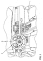
- Fig. 1 shows an embodiment of a motor vehicle 1 in an interior view.
- the motor vehicle 1 comprises an instrument cluster 3 arranged behind a steering wheel 2, by means of which, for example, the speed of the motor vehicle 1, the rotational speed of an engine of the motor vehicle 1, the temperature of the engine of the motor vehicle 1, the tank filling and / or the time can be displayed.
- the instrument cluster 3 for example, expenses of a navigation system, expenses of a telephone, outputs of a music system, expenses of an infotainment system and / or expenses of an air conditioner can be displayed.
- Fig. 2 shows a perspective schematic representation of a portion of the instrument cluster 3.
- elements, angles and distances in Fig. 2 having regard to simplicity and clarity and not necessarily to scale.
- the magnitudes of some elements, angles and distances are exaggerated over other elements, angles and distances to enhance understanding of the embodiment of the present invention.
- the instrument cluster 3 comprises a first display device 15 and a second display device 10.
- the second display device 10 comprises in the present embodiment analog displays for displaying the speed of the motor vehicle 1, the speed of the engine of the motor vehicle 1, the temperature of the engine of the motor vehicle 1 and the tank filling, for reasons of clarity in Fig. 2 only an analog display for displaying the speed of the motor vehicle 1 is shown.
- the analog display for displaying the speed of the motor vehicle 1 comprises a scale 23 and a pointer 21 rotatable about a pointer base 21 for indicating the speed of the motor vehicle 1 on the scale 23.
- the pointer 21 and the scale 23 may, for example, by a in the EP 0 482 805 A1 Illuminated lighting to be illuminated or be designed even bright.
- the first display device 15 is designed as a digital display, by means of which the motor vehicle 1 information such as the speed of the motor vehicle 1, the rotational speed of an engine of the motor vehicle 1, the temperature of an engine of the motor vehicle 1, the tank filling, the time, outputs of a navigation system, Outputs of a telephone, outputs of a music system, expenses of an infotainment system and / or expenses of an air conditioner can be represented digitally.
- Fig. 2 an embodiment of a state is shown in which by means of the first display device 15, a digital indication 16 of the speed of the motor vehicle 1 and a status 17 of a distance control are displayed.
- the combination instrument 3 further comprises a semitransparent mirror 14 for reflecting light emitted by the second display device 10, wherein the semi-transparent mirror 14 is substantially transparent to light emitted by the first display device 15.
- the semitransparent mirror 14 has a substantially transparent surface facing the first display device 15 and a substantially reflective surface facing the second display device 10.
- the first display device 15 and the second display device 10 are arranged substantially orthogonal to each other.
- the semi-transparent mirror 14 is inclined relative to both the first display device 15 and the second display device 10 by approximately 45 °.
- the combination instrument 3 further comprises a disc 11 with adjustable transparency arranged between the semitransparent mirror 14 and the second display device 10.
- the transparent transparency plate 11 comprises a controllable layer 12 which, depending on an applied voltage, in particular by an orthogonal polarization of light, may assume a state in which it is transparent and may assume a state in which it is opaque, it being possible to advantageously switch between these two states in less than 0.1 s.
- the controllable layer 12 may be a twisted nematics layer, a CLC (cholesteric liquid crystal) layer, a PDLC (polymer dispersed liquid crystal) layer and / or a PALC layer.
- instrument cluster 3 To protect the instrument cluster 3, it has a to the interior of the motor vehicle 1 aligned protective disk 19.
- the arrow designated by reference numeral 20 describes the viewing direction of an occupant of the motor vehicle 1.
- the in Fig. 2 only illustrated in a schematic representation of the instrument cluster 3 can other components such as those in the EP 0 482 805 A1 comprising reference numerals 15 and 17.
- the instrument panel 3 is associated with a display controller 25 for controlling the first display device 15, for controlling the second display device 10 and for adjusting the transparency of the disc 11 with adjustable transparency as a function of information displayed by means of the first display device 15.
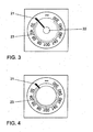
- Fig. 3 shows an image of the second display device 10 of the in Fig. 2 Plane 13 shown by a disc 11 with adjustable transparency seen for a state in which the controllable layer 12 is transparent due to appropriate control by means of the display controller 25.
- the controllable layer 12 assumes this state as a result of corresponding activation by means of the display control 25 when no information displayed by the first display device 15 is to be superimposed in the area of the pointer base 22. If, on the other hand, information to be displayed in the area of the pointer base 22 is displayed by the first display device 15, then the controllable layer 12 is controlled by means of the display control 25 such that it is opaque.
- Fig. 4 shows a corresponding image of the second display device 10 from the plane 13 through a disc 11 with adjustable transparency seen for a state in which the controllable layer 12 is opaque.
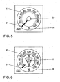
- Fig. 5 shows the instrument cluster 3 from the perspective of an occupant of the motor vehicle 1, ie from in Fig. 2 Viewed level 18, for that too Fig. 3 corresponding state in which the controllable layer 12 is transparent.
- the digital display 16 of the speed of the motor vehicle 1 shown by the first display device 15 is displayed.
- Fig. 6 shows the instrument cluster 3 from the perspective of an occupant of the motor vehicle 1, so viewed from the plane 18, for the zu Fig. 4 corresponding state in which the controllable layer 12 is opaque. Not only the digital indication 16 of the speed of the motor vehicle 1 represented by the first display device 15 but also the status 17 of the distance control shown by the first display device 15 -in the region of the pointer base 22 covered by the opaque controllable layer 12 -is displayed.
Landscapes
- Engineering & Computer Science (AREA)
- Chemical & Material Sciences (AREA)
- Combustion & Propulsion (AREA)
- Transportation (AREA)
- Mechanical Engineering (AREA)
- Instrument Panels (AREA)
- Automatic Cycles, And Cycles In General (AREA)
- Arrangement Or Mounting Of Propulsion Units For Vehicles (AREA)
- Motor Or Generator Cooling System (AREA)
- Details Of Measuring Devices (AREA)
Description
- Die Erfindung betrifft ein Kombiinstrument für ein Kraftfahrzeug mit einer ersten Anzeigeeinrichtung und mit einer zweiten Anzeigeeinrichtung, wobei das Kombiinstrument einen semitransparenten Spiegel zum Reflektieren von mittels der zweiten Anzeigeeinrichtung emittiertem Licht aufweist, und wobei der semitransparente Spiegel für von der ersten Anzeigeeinrichtung emittiertes Licht im wesentlichen transparent ist.
- Ein derart ausgestaltetes Kombiinstrument ist in der deutschen Patentanmeldung
103 33 745.8 beschrieben sowie in derEP 0 482 805 A1 offenbart. - Die
EP 0 648 639 offenbart eine Anzeigevorrichtung mit einer ersten Anzeige und einer zweiten Anzeige. Dabei wird die zweite Anzeige an einer der ersten Anzeige vorgelagerten Reflektionsfläche eingespiegelt, wobei diese Reflektionsfläche in ihrer optischen Transparenz veränderbar ist. - Die Druckschrift
DE 43 23 082 C2 beschreibt eine Anzeigeeinheit für Kraftfahrzeuge mit einer ein erstes Anzeigeelement enthaltenden ersten Anzeigeebene und einer als transparente Scheibe ausgebildeten zweiten Anzeigeebene, auf welcher Informationsinhalte eines zweiten Anzeigeelements sichtbar gemacht werden können. Dabei kann die zweite Anzeigeebene zumindest in einem begrenzten Feld als Licht undurchlässige Projektionsebene ausgebildet werden. - Die Druckschrift
D E 103 33 745 A1 betrifft eine Anzeigeeinrichtung für ein Kraftfahrzeug mit einer ersten Displayeinrichtung, welche abbildendes Licht abgibt, und einer zweiten Anzeigeeinrichtung. Dabei ist die zweite Anzeigeeinrichtung zu der ersten Displayeinrichtung in einem Winkel angeordnet, wobei dazwischen ein Spiegel vorgesehen ist, welcher für das abbildende Licht der ersten Displayeinrichtung durchlässig und für das abbildende Licht der zweiten Anzeigeeinrichtung reflektierend ausgebildet ist. - Aus der
DE 199 43 571 A1 ist ein Kombiinstrument mit einer auf der Rückseite eines Grundkörpers angeordneten starren Leiterplatte bekannt. Dieser Grundkörper wird auf der Vorderseite teilweise von einem Tragkörper abgedeckt, welcher gelenkig mit dem Grundkörper verbunden ist. Über die Vorderseite des Grundkörpers und des Tragkörpers erstreckt sich eine flexible Leiterplatte, welche einen definierten Winkel zu einem Randbereich der starren Leiterplatte umgelenkten Verbindungsbereich umfasst, der durch eine, z. B. Bügellötung, mit dieser Leiterplatte verbunden ist - Aus der
DE 199 41 352 A1 ist ein Kombiinstrument mit einem Grundkörper bekannt, welcher in Anzeigefelder aufgeteilt ist, die mit unterschiedlichen Winkeln zueinander ausgerichtet sind. Auf der Vorderseite des Grundkörpers ist eine sich über mehrere Anzeigefelder erstreckende zusätzliche Leiterplatte angeordnet. Diese besteht aus starren Leiterplattenteilen, welche im Übergangsbereich der Anzeigefelder flexible Verbindungsbereiche mit Leiterbahnen aufweisen. - Aus der
DE 198 19 822 A1 ist ein integriertes Kombiinstrument zum Anzeigen von unterschiedlichen Messdaten in einem Kraftfahrzeug bekannt, das mit analogen und digitalen Anzeigeinstrumenten bestückt ist. Das integrierte Kombiinstrument umfasst eine Einrichtung zur Ansteuerung der Anzeigeinstrumente und zum Durchführen einer oder mehrerer weiterer Funktionen der Karosseriezentralelektronik und Karosserieleistungselektronik und mindestens eine integrierte Sicherungseinrichtung für die Einrichtung. - Aus der
DE 198 19 821 C1 ist ein Kombiinstrument zum Anzeigen von unterschiedlichen Messdaten in einem Kraftfahrzeug bekannt, das mit analogen und digitalen Anzeigeinstrumenten bestückt ist, wobei mechanische, optische und elektrische Bauteile der Anzeigeinstrumente auf einer Schaltungsträgereinrichtung angebracht sind und die elektronische Ansteuerung der Anzeigeinstrumente von einem auf der Schaltungsträgereinrichtung anbringbaren Elektronikmodul aus erfolgt. Die Schaltungsträgereinrichtung weist eine Verdrahtungsfolie auf, die zwischen einer rückseitigen Abdeckung und einer vorderseitigen Abdeckung einspannbar ist. - Aus der
DE 198 19 393 A1 ist ebenfalls ein Kombiinstrument zum Anzeigen von unterschiedlichen Messdaten in einem Kraftfahrzeug bekannt, das mit analogen und digitalen Anzeigeinstrumenten bestückt ist, wobei mechanische, optische und elektrische Bauteile der Anzeigeinstrumente auf einer Trägerplatte gehaltert sind und die elektronische Ansteuerung der Anzeigeinstrumente von einem an der Trägerplatte anbringbaren Elektronikmodul aus erfolgt. Auf der Trägerplatte ist dabei jedoch eine Schaltungsträgereinrichtung zum Tragen der Verdrahtung der elektrischen Bauteile angebracht. - Es ist Aufgabe der Erfindung, die Anzeige von Informationen in einem Kraftfahrzeug zu verbessern.
- Vorgenannte Aufgabe wird durch ein Kombiinstrument für ein Kraftfahrzeug mit den Merkmalen des Anspruchs 1 gelöst, wobei die zweite Anzeigeeinrichtung mittels der Scheibe mit einstellbarer Transparenz wahlweise (ganz oder teilweise) verdeckt werden kann.
- In weiterhin vorteilhafter Ausgestaltung der Erfindung umfasst die Scheibe mit einstellbarer Transparenz zumindest eine Twisted Nematics Schicht, zumindest eine CLC (cholesteric liquid crystal) Schicht, zumindest eine PDLC (polymer dispersed liquid crystal) Schicht und/oder zumindest eine PALC Schicht. Einzelheiten zu Twisted Nematics Schichten können der Internetseite www.toshiba.ca/web/pdf/Innovative display Toshiba final.pdf sowie der Internetseite www.tvtechnology.com/features/Tech-Corner/f_AdvancedDisplays-03.10.04.shtml entnommen werden. PALC Schichten sind in der
US 6 674 419 und derUS 6 597 412 offenbart. - In weiterhin vorteilhafter Ausgestaltung der Erfindung ist die erste Anzeigeeinrichtung als Digitalanzeige ausgestaltet oder umfasst eine Digitalanzeige. Die erste Anzeigeeinrichtung kann z.B. entsprechend der in der
EP 0 482 805 A1 mit Bezugszeichen 12 bezeichneten second image source ausgestaltet werden. - In weiterhin vorteilhafter Ausgestaltung der Erfindung ist die zweite Anzeigeeinrichtung als Analoganzeige ausgestaltet oder umfasst eine Analoganzeige.
- In dem erfindungsgemäßen Kombiinstrument sind vorteilhafterweise der semitransparente Spiegel, die erste Anzeigeeinrichtung und die zweite Anzeigeeinrichtung derart zueinander angeordnet, dass ein Spiegelbild der zweiten Anzeigeeinrichtung für einen Betrachter vor der ersten Anzeigeeinrichtung erscheint. Ein semitransparenter Spiegel im Sinne der Erfindung umfasst insbesondere einen in der
EP 0 482 805 A1 mit Bezugszeichen 13 bezeichneten combiner. - Vorgenannte Aufgabe wird zudem durch ein Kraftfahrzeug mit einem eines oder mehrere der vorgenannten Merkmale umfassenden Kombiinstrument gelöst. Das Kraftfahrzeug umfasst in vorteilhafter Ausgestaltung der Erfindung eine dem Kombiinstrument zugeordnete Anzeigesteuerung zur Einstellung der Transparenz der Scheibe mit einstellbarer Transparenz in Abhängigkeit von mittels der ersten Anzeigeeinrichtung dargestellten Informationen.
- Eine Scheibe mit einstellbarer Transparenz im Sinne der Erfindung ist insbesondere eine Scheibe, die abhängig von einer angelegten Spannung, insbesondere durch eine orthogonale Polarisierung von Licht, einen Zustand annehmen kann, in dem sie transparent ist, und einen Zustand annehmen kann, in dem sie opak ist. Eine Scheibe mit einstellbarer Transparenz im Sinne der Erfindung ist insbesondere eine Scheibe, die einen Zustand annehmen kann, in dem sie transparent ist, und einen Zustand annehmen kann, in dem sie opak ist, wobei zwischen diesen beiden Zuständen vorteilhafterweise in weniger als 0,1s umgeschaltet werden kann.
- Kraftfahrzeug im Sinne der Erfindung ist insbesondere ein individuell im Straßenverkehr benutzbares Landfahrzeug. Kraftfahrzeuge im Sinne der Erfindung sind insbesondere nicht auf Landfahrzeuge mit Verbrennungsmotor beschränkt.
- Weitere Vorteile und Einzelheiten ergeben sich aus der nachfolgenden Beschreibung von Ausführungsbeispielen. Dabei zeigen:
- Fig. 1
- ein Ausführungsbeispiel eines Kraftfahrzeuges in einer Innenansicht,
- Fig. 2
- eine perspektivische Prinzipdarstellung eines Ausführungsbeispiels eines Kombiin- strumentes,
- Fig. 3
- ein Bild einer Anzeigvorrichtung eines Kombiinstrumentes gemäß
Fig. 2 durch eine Scheibe mit einstellbarer Transparenz betrachtet, - Fig. 4
- ein weiteres Bild einer Anzeigvorrichtung eines Kombiinstrumentes gemäß
Fig. 2 durch eine Scheibe mit einstellbarer Transparenz betrachtet, - Fig. 5
- das Kombiinstrument gemäß
Fig. 2 aus der Sicht eines Insassen des Kraftfahrzeuges gemäßFig. 1 und - Fig. 6
- das Kombiinstrument gemäß
Fig. 2 in einem weiteren Zustand aus der Sicht eines Insassen des Kraftfahrzeuges gemäßFig. 1 . -
Fig. 1 zeigt ein Ausführungsbeispiel eines Kraftfahrzeuges 1 in einer Innenansicht. Das Kraftfahrzeug 1 umfasst ein hinter einem Lenkrad 2 angeordnetes Kombiinstrument 3, mittels dessen z.B. die Geschwindigkeit des Kraftfahrzeuges 1, die Drehzahl eines Motors des Kraftfahrzeuges 1, die Temperatur des Motors des Kraftfahrzeuges 1, die Tankfüllung und/oder die Zeit angezeigt werden können. Zudem kann vorgesehen sein, dass mittels des Kombiinstrumentes 3 z.B. Ausgaben eines Navigationssystems, Ausgaben eines Telefons, Ausgaben einer Musikanlage, Ausgaben eines Infotainmentsystems und/oder Ausgaben einer Klimaanlage anzeigbar sind. -
Fig. 2 zeigt eine perspektivische Prinzipdarstellung eines Teils des Kombiinstrumentes 3. Dabei sind Elemente, Winkel und Abstände inFig. 2 unter Berücksichtigung von Einfachheit und Klarheit und nicht notwendigerweise maßstabsgetreu gezeichnet. So sind z.B. die Größenordnungen einiger Elemente, Winkel und Abstände übertrieben gegenüber anderen Elementen, Winkeln und Abständen dargestellt, um das Verständnis des Ausführungsbeispiels der vorliegenden Erfindung zu verbessern. - Das Kombiinstrument 3 umfasst eine erste Anzeigeeinrichtung 15 und eine zweite Anzeigeeinrichtung 10. Die zweite Anzeigeeinrichtung 10 umfasst im vorliegenden Ausführungsbeispiel Analoganzeigen zur Anzeige der Geschwindigkeit des Kraftfahrzeuges 1, der Drehzahl des Motors des Kraftfahrzeuges 1, der Temperatur des Motors des Kraftfahrzeuges 1 und der Tankfüllung, wobei aus Gründen der Übersichtlichkeit in
Fig. 2 nur eine Analoganzeige zur Anzeige der Geschwindigkeit des Kraftfahrzeuges 1 dargestellt ist. Die Analoganzeige zur Anzeige der Geschwindigkeit des Kraftfahrzeuges 1 umfasst eine Skala 23 und einen um eine Zeigerbasis 22 drehbaren Zeiger 21 zur Anzeige der Geschwindigkeit des Kraftfahrzeuges 1 auf der Skala 23. Der Zeiger 21 und die Skala 23 können z.B. durch eine in derEP 0 482 805 A1 offenbarte Beleuchtung beleuchtet werden oder selbst leuchtend ausgestaltet sein. - Die erste Anzeigeeinrichtung 15 ist als Digitalanzeige ausgestaltet, mittels der das Kraftfahrzeug 1 betreffende Informationen wie z.B. die Geschwindigkeit des Kraftfahrzeuges 1, die Drehzahl eines Motors des Kraftfahrzeuges 1, die Temperatur eines Motors des Kraftfahrzeuges 1, die Tankfüllung, die Zeit, Ausgaben eines Navigationssystems, Ausgaben eines Telefons, Ausgaben einer Musikanlage, Ausgaben eines Infotainmentsystems und/oder Ausgaben einer Klimaanlage digital darstellbar sein können. In
Fig. 2 ist ein Ausführungsbeispiel für einen Zustand dargestellt, in dem mittels der ersten Anzeigeeinrichtung 15 eine digitale Angabe 16 der Geschwindigkeit des Kraftfahrzeuges 1 und ein Status 17 einer Abstandsregelung angezeigt werden. - Das Kombiinstrument 3 umfasst zudem einen semitransparenten Spiegel 14 zum Reflektieren von mittels der zweiten Anzeigeeinrichtung 10 emittiertem Licht, wobei der semitransparente Spiegel 14 für von der ersten Anzeigeeinrichtung 15 emittiertes Licht im wesentlichen transparent ist. Dazu weist der semitransparente Spiegel 14 eine der ersten Anzeigeeinrichtung 15 zugewandte im Wesentlichen transparente Oberfläche und eine der zweiten Anzeigeeinrichtung 10 zugewandte im Wesentlichen reflektierende Oberfläche auf. Zudem sind die erste Anzeigeeinrichtung 15 und die zweite Anzeigeeinrichtung 10 im Wesentlichen orthogonal zueinander angeordnet. Der semitransparente Spiegel 14 ist sowohl gegenüber ersten Anzeigeeinrichtung 15 als auch der zweiten Anzeigeeinrichtung 10 gegenüber um in etwa 45° geneigt.
- Das Kombiinstrument 3 umfasst weiterhin eine zwischen dem semitransparenten Spiegel 14 und der zweiten Anzeigeeinrichtung 10 angeordnete Scheibe 11 mit einstellbarer Transparenz. Die Scheibe 11 mit einstellbarer Transparenz umfasst eine steuerbare Schicht 12, die abhängig von einer angelegten Spannung, insbesondere durch eine orthogonale Polarisierung von Licht, einen Zustand annehmen kann, in dem sie transparent ist, und einen Zustand annehmen kann, in dem sie opak ist, wobei zwischen diesen beiden Zuständen vorteilhafterweise in weniger als 0,1s umgeschaltet werden kann. Die steuerbare Schicht 12 kann eine Twisted Nematics Schicht, eine CLC (cholesteric liquid crystal) Schicht, eine PDLC (polymer dispersed liquid crystal) Schicht und/oder eine PALC Schicht sein.
- Zum Schutz des Kombiinstruments 3 weist es eine zum Innenraum des Kraftfahrzeuges 1 ausgerichtete Schutzscheibe 19 auf. Der mit Bezugszeichen 20 bezeichnete Pfeil beschreibt die Blickrichtung eines Insassen des Kraftfahrzeuges 1. Das in
Fig. 2 lediglich in einer Prinzipdarstellung dargestellte Kombiinstrument 3 kann weitere Komponenten wie z.B. die in derEP 0 482 805 A1 mit Bezugszeichen 15 und 17 bezeichneten Spiegel umfassen. - Dem Kombiinstrument 3 ist eine Anzeigesteuerung 25 zur Steuerung der ersten Anzeigeeinrichtung 15, zur Steuerung der zweiten Anzeigeeinrichtung 10 und zur Einstellung der Transparenz der Scheibe 11 mit einstellbarer Transparenz in Abhängigkeit von mittels der ersten Anzeigeeinrichtung 15 dargestellten Informationen zugeordnet.
-
Fig. 3 zeigt ein Bild der zweiten Anzeigeeinrichtung 10 von der inFig. 2 dargestellten Ebene 13 durch eine Scheibe 11 mit einstellbarer Transparenz gesehen für einen Zustand, in dem die steuerbare Schicht 12 bedingt durch entsprechende Ansteuerung mittels der Anzeigesteuerung 25 transparent ist. Diesen Zustand nimmt die steuerbare Schicht 12 bedingt durch entsprechende Ansteuerung mittels der Anzeigesteuerung 25 dann an, wenn im Bereich der Zeigerbasis 22 keine von ersten Anzeigeeinrichtung 15 dargestellten Informationen eingeblendet werden sollen. Sollen dagegen im Bereich der Zeigerbasis 22 von ersten Anzeigeeinrichtung 15 dargestellte Informationen eingeblendet werden, so wird die steuerbare Schicht 12 mittels der Anzeigesteuerung 25 derart angesteuert, dass sie opak ist.Fig. 4 zeigt ein entsprechendes Bild der zweiten Anzeigeeinrichtung 10 von der Ebene 13 durch eine Scheibe 11 mit einstellbarer Transparenz gesehen für einen Zustand, in dem die steuerbare Schicht 12 opak ist. -
Fig. 5 zeigt das Kombiinstrument 3 aus der Sicht eines Insassen des Kraftfahrzeuges 1, also aus der inFig. 2 dargestellten Ebene 18 heraus betrachtet, für den zuFig. 3 korrespondierenden Zustand, in dem die die steuerbare Schicht 12 transparent ist. Dabei wird die von der ersten Anzeigeeinrichtung 15 dargestellte digitale Angabe 16 der Geschwindigkeit des Kraftfahrzeuges 1 eingeblendet. -
Fig. 6 zeigt das Kombiinstrument 3 aus der Sicht eines Insassen des Kraftfahrzeuges 1, also aus der Ebene 18 heraus betrachtet, für den zuFig. 4 korrespondierenden Zustand, in dem die die steuerbare Schicht 12 opak ist. Dabei wird nicht nur die von der ersten Anzeigeeinrichtung 15 dargestellte digitale Angabe 16 der Geschwindigkeit des Kraftfahrzeuges 1 sondern auch der von der ersten Anzeigeeinrichtung 15 - im durch die opake steuerbare Schicht 12 abgedeckten Bereich der Zeigerbasis 22 - dargestellte Status 17 der Abstandsregelung eingeblendet. -
- 1
- Kraftfahrzeug
- 2
- Lenkrad
- 3
- Kombiinstrument
- 10, 15
- Anzeigeeinrichtung
- 11
- Scheibe mit einstellbarer Transparenz
- 12
- steuerbare Schicht
- 13, 18
- Ebene
- 14
- semitransparenter Spiegel
- 16
- digitale Angabe der Geschwindigkeit eines Kraftfahrzeuges
- 17
- Status einer Abstandsregelung
- 19
- Schutzscheibe
- 20
- Pfeil
- 21
- Zeiger
- 22
- Zeigerbasis
- 23
- Skala
- 25
- Anzeigesteuerung
Claims (7)
- Kombiinstrument (3) für ein Kraftfahrzeug (1) mit einer ersten Anzeigeeinrichtung (15) und mit einer zweiten Anzeigeeinrichtung (10), wobei das Kombiinstrument (3) einen semitransparenten Spiegel (14) zum Reflektieren von mittels der zweiten Anzeigeeinrichtung (10) emittiertem Licht aufweist, und wobei der semitransparente Spiegel (14) für von der ersten Anzeigeeinrichtung (15) emittiertes Licht im wesentlichen transparent ist, dadurch gekennzeichnet, dass das Kombiinstrument (3) eine zwischen dem semitransparenten Spiegel (14) und der zweiten Anzeigeeinrichtung (10) angeordnete Scheibe (11) mit einstellbarer Transparenz aufweist, welche separat von dem semitransparenten Spiegel (14) ausgestaltet und parallel zu der zweiten Anzeigeeinrichtung (10) angeordnet ist.
- Kombiinstrument (3) nach Anspruch 1, dadurch gekennzeichnet, dass der semitransparente Spiegel (14) eine der ersten Anzeigeeinrichtung (15) zugewandte im wesentlichen transparente Oberfläche und eine der zweiten Anzeigeeinrichtung (10) zugewandte im Wesentlichen reflektierende Oberfläche aufweist.
- Kombiinstrument (3) nach einem der vorhergehenden Ansprüche, dadurch gekennzeichnet, dass die Scheibe (11) mit einstellbarer Transparenz eine Twisted Nematics Schicht, eine CLC Schicht, eine PDLC Schicht oder eine PALC Schicht aufweist.
- Kombiinstrument (3) nach einem der vorhergehenden Ansprüche, dadurch gekennzeichnet, dass die erste Anzeigeeinrichtung (15) als Digitalanzeige ausgestaltet ist oder eine Digitalanzeige umfasst.
- Kombiinstrument (3) nach einem der vorhergehenden Ansprüche, dadurch gekennzeichnet, dass die zweite Anzeigeeinrichtung (10) als Analoganzeige ausgestaltet ist oder eine Analoganzeige umfasst.
- Kraftfahrzeug (1) dadurch gekennzeichnet, dass es ein Kombiinstrument (3) nach einem der vorhergehenden Ansprüche aufweist.
- Kraftfahrzeug (1) nach Anspruch 6, dadurch gekennzeichnet, dass es eine dem Kombiinstrument (3) zugeordnete Anzeigesteuerung (25) zur Einstellung der Transparenz der Scheibe (11) mit einstellbarer Transparenz in Abhängigkeit von mittels der ersten Anzeigeeinrichtung (15) dargestellten Informationen umfasst.
Applications Claiming Priority (2)
| Application Number | Priority Date | Filing Date | Title |
|---|---|---|---|
| DE102005029800A DE102005029800A1 (de) | 2005-06-27 | 2005-06-27 | Kombiinstrument für ein Kraftfahrzeug |
| PCT/EP2006/003633 WO2007000201A1 (de) | 2005-06-27 | 2006-04-20 | Kombiinstrument für ein kraftfahrzeug |
Publications (2)
| Publication Number | Publication Date |
|---|---|
| EP1899191A1 EP1899191A1 (de) | 2008-03-19 |
| EP1899191B1 true EP1899191B1 (de) | 2010-07-14 |
Family
ID=36676523
Family Applications (1)
| Application Number | Title | Priority Date | Filing Date |
|---|---|---|---|
| EP06742624A Expired - Lifetime EP1899191B1 (de) | 2005-06-27 | 2006-04-20 | Kombiinstrument für ein kraftfahrzeug |
Country Status (4)
| Country | Link |
|---|---|
| EP (1) | EP1899191B1 (de) |
| AT (1) | ATE473882T1 (de) |
| DE (2) | DE102005029800A1 (de) |
| WO (1) | WO2007000201A1 (de) |
Families Citing this family (7)
| Publication number | Priority date | Publication date | Assignee | Title |
|---|---|---|---|---|
| DE102008023839A1 (de) * | 2008-05-16 | 2009-11-26 | Continental Automotive Gmbh | Anzeigeeinrichtung |
| DE102009030470B4 (de) | 2009-06-24 | 2015-12-24 | Johne & Co. Präzisionswerkzeuge GmbH | Wechselkopfhalter-System und Werkzeugkopfelement |
| CN103507639B (zh) * | 2012-06-27 | 2016-06-01 | 比亚迪股份有限公司 | 一种车载显示设备及具有该设备的车辆 |
| CN102837613B (zh) * | 2012-08-21 | 2015-06-17 | 广东好帮手电子科技股份有限公司 | 一种汽车仪表及其指示灯信息提示方法 |
| DE102015002973B4 (de) * | 2015-03-10 | 2020-09-24 | Airbus Defence and Space GmbH | Verfahren zur gemeinsamen Darstellung sicherheitskritischer und nicht-sicherheitskritischer Informationen und Anzeigevorrichtung |
| JP6630698B2 (ja) | 2017-03-24 | 2020-01-15 | 矢崎総業株式会社 | 車両用表示装置 |
| FR3118203B1 (fr) * | 2020-12-21 | 2022-11-04 | Psa Automobiles Sa | Dispositif d’affichage pour véhicule avec image virtuelle paramétrable |
Family Cites Families (12)
| Publication number | Priority date | Publication date | Assignee | Title |
|---|---|---|---|---|
| JPS6444336A (en) * | 1987-08-10 | 1989-02-16 | Nissan Motor | Vehicle display device |
| US5121099A (en) * | 1990-08-31 | 1992-06-09 | Hughes Aircraft Company | Two-page automotive virtual image display |
| DE4323082C2 (de) * | 1993-07-10 | 1997-12-04 | Mannesmann Vdo Ag | Anzeigeeinheit für Kraftfahrzeuge |
| DE4323083A1 (de) * | 1993-07-10 | 1995-01-19 | Vdo Schindling | Multifunktionsschalter zur Betätigung einer ersten und zweiten elektrischen Einrichtung |
| DE4334855A1 (de) * | 1993-10-13 | 1995-04-20 | Bosch Gmbh Robert | Anzeigevorrichtung für Kraftfahrzeuge |
| DE19540813C1 (de) * | 1995-07-19 | 1996-09-05 | Vdo Schindling | Anzeigeeinheit |
| US6597412B1 (en) * | 1999-04-28 | 2003-07-22 | Tektronix, Inc. | Liquid crystal display device employing fiber spacers |
| JP2002362184A (ja) * | 2001-06-11 | 2002-12-18 | Honda Motor Co Ltd | 車両用表示装置 |
| EP1342605B1 (de) * | 2002-03-04 | 2006-07-26 | Ford Global Technologies, LLC | Vorrichtung zur Steuerung einer Bildschirmanzeige |
| DE10333745A1 (de) * | 2003-07-23 | 2005-03-31 | Volkswagen Ag | Anzeigeeinrichtung für ein Kraftfahrzeug |
| DE102004038916A1 (de) * | 2003-09-03 | 2005-03-31 | Volkswagen Ag | Anzeigeeinrichtung für ein Kraftfahrzeug |
| DE10342244B3 (de) * | 2003-09-11 | 2005-04-14 | Siemens Ag | Anzeigevorrichtung |
-
2005
- 2005-06-27 DE DE102005029800A patent/DE102005029800A1/de not_active Withdrawn
-
2006
- 2006-04-20 WO PCT/EP2006/003633 patent/WO2007000201A1/de not_active Ceased
- 2006-04-20 AT AT06742624T patent/ATE473882T1/de active
- 2006-04-20 DE DE502006007436T patent/DE502006007436D1/de not_active Expired - Lifetime
- 2006-04-20 EP EP06742624A patent/EP1899191B1/de not_active Expired - Lifetime
Also Published As
| Publication number | Publication date |
|---|---|
| WO2007000201A1 (de) | 2007-01-04 |
| DE502006007436D1 (de) | 2010-08-26 |
| ATE473882T1 (de) | 2010-07-15 |
| EP1899191A1 (de) | 2008-03-19 |
| DE102005029800A1 (de) | 2007-01-04 |
Similar Documents
| Publication | Publication Date | Title |
|---|---|---|
| DE102005042695B4 (de) | Kraftfahrzeug mit einer Anzeigeanordnung | |
| DE102006032118A1 (de) | Kombiinstrument für ein Kraftfahrzeug | |
| EP1651463B1 (de) | Anzeigeeinrichtung für ein kraftfahrzeug | |
| DE102017212912B4 (de) | Anzeigevorrichtung für ein Kraftfahrzeug, Verfahren zum Betreiben einer Anzeigevorrichtung, Steuereinrichtung, und Kraftfahrzeug | |
| DE10026136B4 (de) | Transparente elektrolumineszierende Anzeige mit mechanischem Messer | |
| DE102017223827B4 (de) | Fahrerbildgebungsvorrichtung | |
| EP1758757A1 (de) | Anzeigevorrichtung für ein kraftfahrzeug | |
| DE102004037816B4 (de) | Einrichtung zum Anzeigen von virtuellen Bildern | |
| WO2007068340A1 (de) | Rückspiegel für ein kraftfahrzeug | |
| DE102007053422A1 (de) | Recheneinrichtung | |
| DE29710675U1 (de) | Anzeigesystem für Fahrzeuge | |
| EP2463152A1 (de) | Beleuchtungselement im Außenspiegel | |
| DE10001988A1 (de) | Display zur Anzeige von betriebs- und/oder verkehrsbezogenen Daten | |
| WO2007000201A1 (de) | Kombiinstrument für ein kraftfahrzeug | |
| DE102018212046A1 (de) | Verfahren zum Bereitstellen einer Anzeige in einem Kraftfahrzeug sowie Anzeigevorrichtung für ein Kraftfahrzeug | |
| DE102008052420B4 (de) | Anzeigevorrichtung für ein Fahrzeug | |
| DE102017101980A1 (de) | Anzeigevorrichtung für den Innenraum eines Kraftfahrzeugs | |
| DE102016123257B3 (de) | Anzeigeeinrichtung für ein Kraftfahrzeug | |
| WO2008055606A1 (de) | Kombiinstrument für ein kraftfahrzeug | |
| DE102008032061B4 (de) | Anzeigevorrichtung für den Innenraum eines Fahrzeugs | |
| DE102019134514A1 (de) | Kraftfahrzeug mit einem Head-up-Display, Verfahren zum Betreiben einer Anzeigevorrichtung mit einem Head-up-Display, und Steuereinrichtung | |
| DE102023100331B3 (de) | Anzeigesystem und Verfahren zum Darstellen eines Anzeigeinhalts | |
| DE3902674C2 (de) | Anzeigedarstellungsvorrichtung für Fahrzeuge | |
| DE4425204C2 (de) | Entspiegelte Anzeigevorrichtung für Kraftfahrzeuge | |
| EP0949109A2 (de) | Anzeigeeinrichtung in Kraftfahrzeugen zur digitalen oder analogen Anzeige von betriebsbezogenen Daten |
Legal Events
| Date | Code | Title | Description |
|---|---|---|---|
| PUAI | Public reference made under article 153(3) epc to a published international application that has entered the european phase |
Free format text: ORIGINAL CODE: 0009012 |
|
| 17P | Request for examination filed |
Effective date: 20080128 |
|
| AK | Designated contracting states |
Kind code of ref document: A1 Designated state(s): AT BE BG CH CY CZ DE DK EE ES FI FR GB GR HU IE IS IT LI LT LU LV MC NL PL PT RO SE SI SK TR |
|
| 17Q | First examination report despatched |
Effective date: 20080611 |
|
| DAX | Request for extension of the european patent (deleted) | ||
| GRAP | Despatch of communication of intention to grant a patent |
Free format text: ORIGINAL CODE: EPIDOSNIGR1 |
|
| GRAS | Grant fee paid |
Free format text: ORIGINAL CODE: EPIDOSNIGR3 |
|
| GRAA | (expected) grant |
Free format text: ORIGINAL CODE: 0009210 |
|
| AK | Designated contracting states |
Kind code of ref document: B1 Designated state(s): AT BE BG CH CY CZ DE DK EE ES FI FR GB GR HU IE IS IT LI LT LU LV MC NL PL PT RO SE SI SK TR |
|
| REG | Reference to a national code |
Ref country code: GB Ref legal event code: FG4D Free format text: NOT ENGLISH |
|
| REG | Reference to a national code |
Ref country code: CH Ref legal event code: EP |
|
| REG | Reference to a national code |
Ref country code: IE Ref legal event code: FG4D |
|
| REF | Corresponds to: |
Ref document number: 502006007436 Country of ref document: DE Date of ref document: 20100826 Kind code of ref document: P |
|
| REG | Reference to a national code |
Ref country code: NL Ref legal event code: VDEP Effective date: 20100714 |
|
| LTIE | Lt: invalidation of european patent or patent extension |
Effective date: 20100714 |
|
| PG25 | Lapsed in a contracting state [announced via postgrant information from national office to epo] |
Ref country code: NL Free format text: LAPSE BECAUSE OF FAILURE TO SUBMIT A TRANSLATION OF THE DESCRIPTION OR TO PAY THE FEE WITHIN THE PRESCRIBED TIME-LIMIT Effective date: 20100714 Ref country code: FI Free format text: LAPSE BECAUSE OF FAILURE TO SUBMIT A TRANSLATION OF THE DESCRIPTION OR TO PAY THE FEE WITHIN THE PRESCRIBED TIME-LIMIT Effective date: 20100714 Ref country code: LT Free format text: LAPSE BECAUSE OF FAILURE TO SUBMIT A TRANSLATION OF THE DESCRIPTION OR TO PAY THE FEE WITHIN THE PRESCRIBED TIME-LIMIT Effective date: 20100714 |
|
| REG | Reference to a national code |
Ref country code: IE Ref legal event code: FD4D |
|
| PG25 | Lapsed in a contracting state [announced via postgrant information from national office to epo] |
Ref country code: SI Free format text: LAPSE BECAUSE OF FAILURE TO SUBMIT A TRANSLATION OF THE DESCRIPTION OR TO PAY THE FEE WITHIN THE PRESCRIBED TIME-LIMIT Effective date: 20100714 Ref country code: PT Free format text: LAPSE BECAUSE OF FAILURE TO SUBMIT A TRANSLATION OF THE DESCRIPTION OR TO PAY THE FEE WITHIN THE PRESCRIBED TIME-LIMIT Effective date: 20101115 Ref country code: PL Free format text: LAPSE BECAUSE OF FAILURE TO SUBMIT A TRANSLATION OF THE DESCRIPTION OR TO PAY THE FEE WITHIN THE PRESCRIBED TIME-LIMIT Effective date: 20100714 Ref country code: IS Free format text: LAPSE BECAUSE OF FAILURE TO SUBMIT A TRANSLATION OF THE DESCRIPTION OR TO PAY THE FEE WITHIN THE PRESCRIBED TIME-LIMIT Effective date: 20101114 Ref country code: CY Free format text: LAPSE BECAUSE OF FAILURE TO SUBMIT A TRANSLATION OF THE DESCRIPTION OR TO PAY THE FEE WITHIN THE PRESCRIBED TIME-LIMIT Effective date: 20100714 Ref country code: BG Free format text: LAPSE BECAUSE OF FAILURE TO SUBMIT A TRANSLATION OF THE DESCRIPTION OR TO PAY THE FEE WITHIN THE PRESCRIBED TIME-LIMIT Effective date: 20101014 |
|
| PG25 | Lapsed in a contracting state [announced via postgrant information from national office to epo] |
Ref country code: LV Free format text: LAPSE BECAUSE OF FAILURE TO SUBMIT A TRANSLATION OF THE DESCRIPTION OR TO PAY THE FEE WITHIN THE PRESCRIBED TIME-LIMIT Effective date: 20100714 Ref country code: SE Free format text: LAPSE BECAUSE OF FAILURE TO SUBMIT A TRANSLATION OF THE DESCRIPTION OR TO PAY THE FEE WITHIN THE PRESCRIBED TIME-LIMIT Effective date: 20100714 Ref country code: GR Free format text: LAPSE BECAUSE OF FAILURE TO SUBMIT A TRANSLATION OF THE DESCRIPTION OR TO PAY THE FEE WITHIN THE PRESCRIBED TIME-LIMIT Effective date: 20101015 |
|
| PG25 | Lapsed in a contracting state [announced via postgrant information from national office to epo] |
Ref country code: DK Free format text: LAPSE BECAUSE OF FAILURE TO SUBMIT A TRANSLATION OF THE DESCRIPTION OR TO PAY THE FEE WITHIN THE PRESCRIBED TIME-LIMIT Effective date: 20100714 Ref country code: IE Free format text: LAPSE BECAUSE OF FAILURE TO SUBMIT A TRANSLATION OF THE DESCRIPTION OR TO PAY THE FEE WITHIN THE PRESCRIBED TIME-LIMIT Effective date: 20100714 |
|
| PLBE | No opposition filed within time limit |
Free format text: ORIGINAL CODE: 0009261 |
|
| STAA | Information on the status of an ep patent application or granted ep patent |
Free format text: STATUS: NO OPPOSITION FILED WITHIN TIME LIMIT |
|
| PG25 | Lapsed in a contracting state [announced via postgrant information from national office to epo] |
Ref country code: EE Free format text: LAPSE BECAUSE OF FAILURE TO SUBMIT A TRANSLATION OF THE DESCRIPTION OR TO PAY THE FEE WITHIN THE PRESCRIBED TIME-LIMIT Effective date: 20100714 Ref country code: RO Free format text: LAPSE BECAUSE OF FAILURE TO SUBMIT A TRANSLATION OF THE DESCRIPTION OR TO PAY THE FEE WITHIN THE PRESCRIBED TIME-LIMIT Effective date: 20100714 Ref country code: SK Free format text: LAPSE BECAUSE OF FAILURE TO SUBMIT A TRANSLATION OF THE DESCRIPTION OR TO PAY THE FEE WITHIN THE PRESCRIBED TIME-LIMIT Effective date: 20100714 Ref country code: IT Free format text: LAPSE BECAUSE OF FAILURE TO SUBMIT A TRANSLATION OF THE DESCRIPTION OR TO PAY THE FEE WITHIN THE PRESCRIBED TIME-LIMIT Effective date: 20100714 Ref country code: CZ Free format text: LAPSE BECAUSE OF FAILURE TO SUBMIT A TRANSLATION OF THE DESCRIPTION OR TO PAY THE FEE WITHIN THE PRESCRIBED TIME-LIMIT Effective date: 20100714 |
|
| 26N | No opposition filed |
Effective date: 20110415 |
|
| PG25 | Lapsed in a contracting state [announced via postgrant information from national office to epo] |
Ref country code: ES Free format text: LAPSE BECAUSE OF FAILURE TO SUBMIT A TRANSLATION OF THE DESCRIPTION OR TO PAY THE FEE WITHIN THE PRESCRIBED TIME-LIMIT Effective date: 20101025 |
|
| REG | Reference to a national code |
Ref country code: DE Ref legal event code: R097 Ref document number: 502006007436 Country of ref document: DE Effective date: 20110415 |
|
| BERE | Be: lapsed |
Owner name: VOLKSWAGEN A.G. Effective date: 20110430 |
|
| PG25 | Lapsed in a contracting state [announced via postgrant information from national office to epo] |
Ref country code: MC Free format text: LAPSE BECAUSE OF NON-PAYMENT OF DUE FEES Effective date: 20110430 |
|
| REG | Reference to a national code |
Ref country code: CH Ref legal event code: PL |
|
| GBPC | Gb: european patent ceased through non-payment of renewal fee |
Effective date: 20110420 |
|
| REG | Reference to a national code |
Ref country code: FR Ref legal event code: ST Effective date: 20111230 |
|
| PG25 | Lapsed in a contracting state [announced via postgrant information from national office to epo] |
Ref country code: CH Free format text: LAPSE BECAUSE OF NON-PAYMENT OF DUE FEES Effective date: 20110430 Ref country code: FR Free format text: LAPSE BECAUSE OF NON-PAYMENT OF DUE FEES Effective date: 20110502 Ref country code: BE Free format text: LAPSE BECAUSE OF NON-PAYMENT OF DUE FEES Effective date: 20110430 Ref country code: LI Free format text: LAPSE BECAUSE OF NON-PAYMENT OF DUE FEES Effective date: 20110430 |
|
| PG25 | Lapsed in a contracting state [announced via postgrant information from national office to epo] |
Ref country code: GB Free format text: LAPSE BECAUSE OF NON-PAYMENT OF DUE FEES Effective date: 20110420 |
|
| REG | Reference to a national code |
Ref country code: AT Ref legal event code: MM01 Ref document number: 473882 Country of ref document: AT Kind code of ref document: T Effective date: 20110420 |
|
| PG25 | Lapsed in a contracting state [announced via postgrant information from national office to epo] |
Ref country code: AT Free format text: LAPSE BECAUSE OF NON-PAYMENT OF DUE FEES Effective date: 20110420 |
|
| PG25 | Lapsed in a contracting state [announced via postgrant information from national office to epo] |
Ref country code: LU Free format text: LAPSE BECAUSE OF NON-PAYMENT OF DUE FEES Effective date: 20110420 |
|
| PG25 | Lapsed in a contracting state [announced via postgrant information from national office to epo] |
Ref country code: TR Free format text: LAPSE BECAUSE OF FAILURE TO SUBMIT A TRANSLATION OF THE DESCRIPTION OR TO PAY THE FEE WITHIN THE PRESCRIBED TIME-LIMIT Effective date: 20100714 |
|
| PG25 | Lapsed in a contracting state [announced via postgrant information from national office to epo] |
Ref country code: HU Free format text: LAPSE BECAUSE OF FAILURE TO SUBMIT A TRANSLATION OF THE DESCRIPTION OR TO PAY THE FEE WITHIN THE PRESCRIBED TIME-LIMIT Effective date: 20100714 |
|
| PGFP | Annual fee paid to national office [announced via postgrant information from national office to epo] |
Ref country code: DE Payment date: 20170430 Year of fee payment: 12 |
|
| REG | Reference to a national code |
Ref country code: DE Ref legal event code: R119 Ref document number: 502006007436 Country of ref document: DE |
|
| PG25 | Lapsed in a contracting state [announced via postgrant information from national office to epo] |
Ref country code: DE Free format text: LAPSE BECAUSE OF NON-PAYMENT OF DUE FEES Effective date: 20181101 |