EP1899211B1 - Dispositifs electroniques pour bagages - Google Patents
Dispositifs electroniques pour bagages Download PDFInfo
- Publication number
- EP1899211B1 EP1899211B1 EP06772620A EP06772620A EP1899211B1 EP 1899211 B1 EP1899211 B1 EP 1899211B1 EP 06772620 A EP06772620 A EP 06772620A EP 06772620 A EP06772620 A EP 06772620A EP 1899211 B1 EP1899211 B1 EP 1899211B1
- Authority
- EP
- European Patent Office
- Prior art keywords
- handle
- transport device
- wheeled transport
- wheeled
- wifi
- Prior art date
- Legal status (The legal status is an assumption and is not a legal conclusion. Google has not performed a legal analysis and makes no representation as to the accuracy of the status listed.)
- Not-in-force
Links
- 230000013011 mating Effects 0.000 claims description 5
- 230000000717 retained effect Effects 0.000 claims description 3
- 238000000034 method Methods 0.000 description 15
- 229920001690 polydopamine Polymers 0.000 description 5
- 230000000994 depressogenic effect Effects 0.000 description 4
- 239000000725 suspension Substances 0.000 description 4
- 230000004913 activation Effects 0.000 description 3
- 239000000463 material Substances 0.000 description 3
- 230000007246 mechanism Effects 0.000 description 3
- 239000004033 plastic Substances 0.000 description 3
- 229920003023 plastic Polymers 0.000 description 3
- 230000009849 deactivation Effects 0.000 description 2
- 239000012530 fluid Substances 0.000 description 2
- 239000000446 fuel Substances 0.000 description 2
- 230000033001 locomotion Effects 0.000 description 2
- 239000002184 metal Substances 0.000 description 2
- 229910052751 metal Inorganic materials 0.000 description 2
- 150000002739 metals Chemical class 0.000 description 2
- 239000007779 soft material Substances 0.000 description 2
- 238000000638 solvent extraction Methods 0.000 description 2
- 239000000853 adhesive Substances 0.000 description 1
- 230000001070 adhesive effect Effects 0.000 description 1
- 230000009286 beneficial effect Effects 0.000 description 1
- 230000005540 biological transmission Effects 0.000 description 1
- 230000008878 coupling Effects 0.000 description 1
- 238000010168 coupling process Methods 0.000 description 1
- 238000005859 coupling reaction Methods 0.000 description 1
- 230000001419 dependent effect Effects 0.000 description 1
- 230000000881 depressing effect Effects 0.000 description 1
- 239000004744 fabric Substances 0.000 description 1
- 239000006260 foam Substances 0.000 description 1
- 238000010295 mobile communication Methods 0.000 description 1
- 230000003287 optical effect Effects 0.000 description 1
- 238000010248 power generation Methods 0.000 description 1
- 238000005096 rolling process Methods 0.000 description 1
- 239000012815 thermoplastic material Substances 0.000 description 1
Images


Classifications
-
- A—HUMAN NECESSITIES
- A45—HAND OR TRAVELLING ARTICLES
- A45C—PURSES; LUGGAGE; HAND CARRIED BAGS
- A45C13/00—Details; Accessories
- A45C13/26—Special adaptations of handles
- A45C13/28—Combinations of handles with other devices
-
- A—HUMAN NECESSITIES
- A45—HAND OR TRAVELLING ARTICLES
- A45C—PURSES; LUGGAGE; HAND CARRIED BAGS
- A45C13/00—Details; Accessories
- A45C13/26—Special adaptations of handles
- A45C13/262—Special adaptations of handles for wheeled luggage
-
- A—HUMAN NECESSITIES
- A45—HAND OR TRAVELLING ARTICLES
- A45C—PURSES; LUGGAGE; HAND CARRIED BAGS
- A45C15/00—Purses, bags, luggage or other receptacles covered by groups A45C1/00 - A45C11/00, combined with other objects or articles
-
- A—HUMAN NECESSITIES
- A45—HAND OR TRAVELLING ARTICLES
- A45C—PURSES; LUGGAGE; HAND CARRIED BAGS
- A45C5/00—Rigid or semi-rigid luggage
- A45C5/14—Rigid or semi-rigid luggage with built-in rolling means
Definitions
- This invention relates to electronic devices for luggage.
- Luggage devices are commonly used by travelers.
- luggage devices can be wheeled by the user.
- a luggage device can, for example, include wheels attached to a lower portion of the luggage device, and a handle attached to an upper portion of the luggage device.
- the user can grasp the handle and push or pull the luggage device such that its wheels roll along the ground surface to convey the luggage device.
- Travelers can carry a wide range of goods in luggage devices.
- U.S. 2004/0196154 discloses a retractable handle bar assembly incorporated with a traveling container includes a hand bar having a receiving cavity, a retractable arm for slidably folding the hand bar between a folded position and an unfolded position, locking device for locking the hand bar at the folded position, and a safety alert system, which is received in the receiving cavity of the hand bar, including an alert signal generator arranged in such a manner that when the hand bar is unlocked to slid from the folded position, the alert signal generator is activated to produce alert signals for aiding an attention of the container body.
- WO 2004/045729 discloses a system for generating and supplying electrical energy, in particular for mobile communications systems, said system exploiting the rolling motion of wheels (30), e.g. on wheeled cases, for generating energy.
- the invention provides a wheeled transport device according to claim 1. Preferred embodiments are described in the dependent claims.
- the invention features a wheeled transport device configured to be manually wheeled by a pedestrian user.
- the wheeled transport device includes a body defining a compartment configured to contain goods, at least one wheel disposed at a lower portion of the body and secured to the body for rotation along a surface upon which the user is walking, a handle attached to an upper portion of the body, and an electronic device mounted to the handle.
- the handle is configured to retract within a cavity defmed by the body.
- the wheeled transport device includes an electronic device mounted to the handle; the wheeled transport device further comprises a switch configured to electrically connect the electronic device to a power supply, wherein the switch is configured to disconnect electrical supply to the electronic device when the handle is retracted to deactivate the electronic device when the handle is retracted, wherein the electrical switch is automatically actuated so that the electronic device is automatically activated upon extending the handle and automatically deactivated upon retracting the handle.
- the invention features a wheeled transport device configured to be manually wheeled by a pedestrian user.
- the wheeled transport device includes a body defining a compartment configured to contain goods, at least one wheel disposed at a lower portion of the body and secured to the body for rotation along a surface upon which the user is walking, and a handle attached to an upper portion of the body.
- the handle is configured to retract within a cavity defined by the body, and includes a first portion and a second portion that is detachable from the first portion.
- An electronic device is mounted to the second portion of the handle.
- Embodiments can include one or more of the following features.
- the wheeled transport device further includes a switch configured to electrically connect the electronic device to a power supply.
- the switch is positioned within the handle.
- the switch is configured to disconnect electrical supply to the electronic device when the handle is retracted.
- the wheeled transport device further includes an electrical contact configured to contact the switch when the handle is extended.
- the electrical contact is electrically connected to the electronic device.
- the electrical contact is positioned within the cavity.
- the power supply is positioned within the body.
- the power supply includes a battery.
- the power supply includes an electric generator operably coupled to the wheel and configured to produce electrical energy as the user wheels the device along the surface.
- the power supply is positioned within the handle.
- the electronic device includes a WiFi locator, a clock, a custom computer, a PDA, a calculator, an expense counter, a cell phone, a GPS device, and/or a luggage locating device.
- the electronic device is releasably attached to the handle.
- the electronic device is constructed to be retained within a recess defined by the handle.
- the handle is a telescoping handle.
- the handle includes two substantially parallel members and a cross member that connects the substantially parallel members.
- the electronic device is attached to the cross member.
- the electronic device is releasably attached to the cross member.
- the electronic device is constructed to be retained within a recess defined by the cross member.
- the electronic device is attached to at least one of the substantially parallel members.
- the electronic device is attached to each of the substantially parallel members.
- the wheeled transport device includes a wheeled luggage device.
- the WiFi locating device is configured to retract within the cavity when the handle is retracted.
- the WiFi locating device is not visible to a user when retracted within the cavity.
- the cavity is defined by relatively hard surfaces to protect the WiFi locating device from damage when the WiFi locating device is retracted.
- the hard surfaces of the cavity include a thermoplastic material.
- the WiFi locating device is configured to deactivate upon retracting the handle.
- the wheeled transport device further includes an electrical switch
- the WiFi locating device includes a contact member configured to electrically contact the electrical switch when the handle is extended.
- the wheeled transport device further includes a power supply.
- the power supply is positioned within the body.
- the power supply is positioned within the handle.
- the power supply includes an electric generator operably coupled to the wheel and configured to produce electrical energy as the user wheels the device along the surface.
- the electric generator is positioned within the body.
- the wheeled transport device further includes an indicator connected to the WiFi locating device.
- the indicator is mounted to the handle.
- the indicator is adapted to indicate a strength of the WiFi signals detected by the WiFi locating device to a user.
- the indicator includes a monitor that visually indicates the strength of the WiFi signals detected by the WiFi locating device to the user.
- the indicator includes an audio device that audibly indicates the strength of the WiFi signals detected by the WiFi locating device to the user.
- the grip portion defines a recess, and the electronic device is mounted within the recess.
- the wheeled transport device further includes an electrical contact positioned within the recess, and the electrical contact is connected to a power supply.
- the electronic device includes an electrical contact.
- the electrical contact of the electronic device is configured to contact the electrical contact within the recess when the electronic device is mounted within the recess.
- multiple electronic devices are mounted to the grip portion of the handle.
- the electronic device is one of a plurality of interchangeable devices configured to be releasably mounted to the handle.
- the interchangeable electronic devices are configured to be releasably mounted to the grip portion of the handle.
- the plurality of interchangeable electronic devices include a WiFi locator, a clock, a custom computer, a PDA, a calculator, an expense counter, a cell phone, a GPS device, and/or a luggage locating device.
- the first and second portions of the handle include mating features adapted to engage one another to secure the first and second portions to one another.
- the mating features include a projection and a slot configured to receive the projection.
- the handle includes a locking member adapted to lock the first and second portions in a joined configuration.
- the locking member includes a mechanical fastener.
- the wheeled transport device further includes a power supply adapted to provide the electronic device with energy.
- the power supply is positioned within the handle.
- the power supply is positioned within the second portion of the handle.
- the power supply is positioned includes electrical contacts electrically connected to the power supply.
- the electrical contacts of the first portion are configured to mate with electrical contacts of the second portion when the first and second portions are secured to one another.
- Embodiments include one or more of the following advantages.
- the electronic device is automatically activated upon extending the handle and/or automatically deactivated upon retracting the handle. This can simplify use of the electronic device by preventing the user from having to perform the additional steps of turning the electronic device on and off.
- the feature that the electronic device is automatically deactivated when the handle is retracted can further help to ensure that the user complies with airline regulations, which require the deactivation of many types of electronic devices during flight.
- the electronic device is attached to a grip portion of the handle. This can help to provide convenience to the user. For example, displays of the electronic devices can be conveniently located in a location that is easily visible to the user during use. In some cases, the presence of the electronic device on the handle can prevent the user from having to access additional electronic devices, such as laptop computers or PDAs, while toting the luggage device.
- the luggage devices include an electric generator that is operatively attached to the wheels of the luggage device. This arrangement can help to generate energy to be provided to the electronic devices.
- a portion of the handle including the electronic device is detachable from the remainder of the handle. This can help to prevent theft and/or damage to the electronic device.
- the luggage devices include multiple, interchangeable electronic devices that can be operatively attached to the handle. This can help to provide the user and/or the manufacturer with the ability to customize the luggage device to provide any of various desired functions.
- the luggage devices include an electronic device (e.g., a WiFi detector) that is attached to a retractable handle.
- the electronic device can generally be retracted into a body of the luggage device along with the handle.
- the electronic device is automatically activated upon extending the handle and automatically deactivated upon retracting the handle.
- the portion of the handle that includes the electronic device is detachable from the rest of the handle.
- a luggage device 100 includes a body 105 and a retractable handle 110.
- Retractable handle 110 can be retracted into an interior region of the body 105.
- a WiFi locator 135 is mounted within handle 110.
- WiFi locator 135 can detect wireless signals, such as wireless internet signals. During use, the user can, for example, determine whether a wireless signal is present in the area by examining the handle of the luggage device rather than having to access an additional device, such as a laptop computer or a PDA.
- Body 105 defines a cavity 130 that is sized and shaped to receive handle 110 when it is retracted.
- the portion of body 105 that defines cavity 130 can be formed of any of various materials.
- this portion of body 105 is formed of one or more durable materials in order to help protect WiFi locator 135 when handle 110 and WiFi locator 135 are retracted.
- This portion of body 105 can, for example, be formed of any of various metals or plastics.
- the interior region of cavity 130 includes a soft material, such as foam or cloth, to provide WiFi locator 135 with added cushion, which can further help to prevent WiFi locator 135 from being damaged while handle 110 is retracted.
- Handle 110 includes two parallel members 115 and a grip portion 120 that is attached to and connects parallel members 115.
- Handle 110 includes a recess 125 through which the user can place his or her hand to grasp grip portion 120 in order to push and/or pull luggage device 100.
- the user can, for example, tote the luggage device along a ground surface such that wheels 119, which extend from a bottom surface of the luggage device, roll on the ground surface.
- Parallel members 115 and/or grip portion 120 can be formed of any of various materials, such as metals and/or plastics.
- the region of grip portion 120 that is grasped by the user during use (e.g., the region of grip portion 120 adjacent recess 125) is formed of a soft material, such as a soft plastic or rubber.
- grip portion 120 can provide comfort to the user during use.
- WiFi locator 135, as shown in Figs. 1 and 2 can be positioned on the face of grip portion 120 such that WiFi locator 135 (e.g., a display unit of WiFi locator 135) is visible to the user while the luggage device is being toted.
- WiFi locator 135 includes a power source (not shown) that is configured to provide energy to electrical components of WiFi locator 135 to permit operation of WiFi locator 135.
- the power source is a battery (e.g., a primary or secondary battery) that is contained within a battery compartment of WiFi locator 135.
- any of various other types of power sources such as fuel cells, solar cells, and/or A/C adaptors, can alternatively or additionally be used.
- WiFi locator 135 can be attached to grip portion 120 so that WiFi locator 135 can be viewed by the user during use.
- WiFi locator 135 is releasably attached to grip portion 120.
- grip portion 120 includes a cavity 140 that is sized and shaped to receive WiFi locator 135.
- a blind hole 147 is also formed in grip portion 120.
- Blind hole 147 extends from cavity 140 into grip portion 120.
- WiFi locator 135 includes a resilient prong 145 that is configured (e.g., sized and shaped) to snap into blind hole 147 when WiFi locator 135 is positioned within cavity 150.
- WiFi locator 135 is also equipped with a button switch 160 that is configured to activate and deactivate WiFi locator 135.
- Button switch 160 can be arranged such that it deactivates WiFi locator 135 when handle 110 is retracted and activates WiFi locator 135 when handle 110 is extended.
- Button switch 160 is configured such that WiFi locator 135 is deactivated upon depressing the switch and activated upon releasing the switch, or vice versa.
- button switch 160 can include a conductive element that completes an electrical circuit connecting WiFi locator 135 to the power source contained therein when button switch 160 is released, and interrupts the electrical circuit when button switch 160 is depressed.
- the button switch can be activated and deactivated by arranging button switch 160 along handle 110 so that the button of button switch 160 is depressed by a surface of body 105 when handle 110 is retracted. Any of various types of button switches can be used.
- WiFi locator 135 To releasably attach WiFi locator 135 to grip portion 120, the user can position WiFi locator 135 within cavity 140 such that only the edge of WiFi locator 135 that includes resilient prong 145 remains outside of cavity 40. Button switch 160 of WiFi locator 135 can be positioned such that its button extends through an aperture defined in the lower portion of grip portion 120 and below grip portion 120. The user can then apply a force to the edge of WiFi locator 135 including resilient prong 145 causing resilient prong 145 to deflect and then snap into blind hole 147. As an alternative to or in addition to the above-described technique for releasably mounting WiFi locator 135 to grip portion 120, any of various other suitable techniques can be used.
- Such techniques include other snap-fitting techniques, fastening techniques that involve the use of mechanical fasteners (e.g., screws, hook and loop fasteners, quarter turn fasteners), friction fit techniques, interference fit techniques, track systems, and techniques involving the use of adhesives.
- mechanical fasteners e.g., screws, hook and loop fasteners, quarter turn fasteners
- friction fit techniques e.g., friction fit techniques, interference fit techniques, track systems, and techniques involving the use of adhesives.
- handle 110 can be arranged in an extended position, as shown in Fig. 1 , so that the user can roll luggage device 100 along a surface.
- handle 110 can be retracted into cavity 130, which is formed in the interior region of body 105.
- the button of button switch 160 which extends below the lower surface of grip portion 120, contacts, an inner surface of cavity 130, causing the button to be depressed.
- WiFi locator 135 is deactivated.
- the button of button switch 160 is released, which results in the activation of WiFi locator 135.
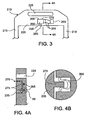
- a luggage device handle 210 has a grip portion 220 that includes a battery 250 and a WiFi locator 235.
- Battery 250 is electrically connected by wires 255 to conductive tracks 265, which extend along the surface of a cavity 270 formed within grip portion 220.
- WiFi locator 235 can be positioned within cavity 270 to electrically connect WiFi locator 235 to conductive tracks 265 and thus to battery 250.
- Fig. 3 for example, a luggage device handle 210 has a grip portion 220 that includes a battery 250 and a WiFi locator 235.
- Battery 250 is electrically connected by wires 255 to conductive tracks 265, which extend along the surface of a cavity 270 formed within grip portion 220.
- WiFi locator 235 can be positioned within cavity 270 to electrically connect WiFi locator 235 to conductive tracks 265 and thus to battery 250.
- WiFi locator 235 includes conductive members 275 that are configured to fit within elongated sections of cavity 270 in which conductive tracks 265 are positioned. Conductive members 275 of WiFi locator 235 contact conductive tracks 265, which creates an electrical circuit extending between battery 250 and WiFi locator 235.
- conductive tracks 265 are conductive spring clips that clip onto conductive members 275 when WiFi locator 235 is positioned within cavity 270. The spring clips, in addition to providing an electrical connection, can help to retain WiFi locator 235 within cavity 270.
- conductive members 275 are shaped similarly to the spring clips to further enhance the ability of the spring clip to retain WiFi locator 235 within cavity 270. Alternatively or additionally, any of the various other fastening techniques described above can be used to help secure WiFi locator 235 within cavity 270.
- WiFi locator 235 also includes a button switch 260, which is similar to button switch 160 described above.
- Button switch 260 can be configured to deactivate WiFi locator 235 (e.g., by interrupting the electrical circuit formed between WiFi locator 235 and battery 250) when handle 210 is retracted into the body of the luggage device and to activate WiFi locator 235 when handle 210 is extended.
- multiple electronic devices can be mounted to grip portion 220.
- cavity 270 is sized to receive multiple electronic devices 236 in addition to WiFi locator 235.
- the electronic devices can be any of various devices. Examples of electronic devices include WiFi locators, clocks, custom computers, PDAs, calculators, expense counters, cell phones, GPS devices, and luggage locating devices (e.g., a wireless transmitter/receiver, an RF transmitter/receiver).
- the user can retain the receiver of the device while the transmitter remains attached to the luggage. Thus, the user can locate his or her luggage by receiving wireless transmission from the transmitter.
- Each of electronic devices 236 can include conductive members (similar to conductive members 275 of WiFi locator 235) that contact conductive tracks 265 when the electronic devices are positioned within cavity 270. Consequently, each of the multiple electronic devices can be powered by battery 250. In a manner similar to that described above, button switch 260 can be depressed to cut off the electrical current to each of electronic devices 235. Thus, upon retracting handle 210 into the body of the luggage device, each of the electronic devices can be deactivated.
- each of the electronic devices can include fastening members that engage grip portion 220 and prevent movement along the length of grip portion 220.
- an end piece or insert including fastening members can be positioned at the opening of cavity 270 in order to prevent the electronic devices from sliding out of cavity 270.
- multiple interchangeable electronic devices can be provided (e.g., sold with the luggage device or sold separately). Depending on the user's needs, certain of the devices can be interchanged for others.
- a luggage device 300 includes a retractable handle 310 and a body 305. Like the embodiments described above, a grip portion 320 of handle 310 includes a WiFi locator 335. Body 305 of luggage device 300 houses a generator 365 and a rechargeable battery 370. Generator 365 is operatively attached to a wheel 319 of luggage device 300 such that rotation of wheel 319 generates energy within generator 365. Rechargeable battery 370 is connected to generator 365 by a wire 372. Energy generated within generator 365 can be transferred via wire 372 to battery 370 where it can be stored for use.
- Battery 370 is connected to WiFi locator 335 by wire 374.
- WiFi locator 335 when WiFi locator 335 is activated, energy can be transferred via wire 374 from battery 370 to WiFi locator 335.
- Wire 374 can be electrically connected to WiFi locator 335 using any of the various configurations and techniques described above, as well as any other suitable configurations and techniques.
- the luggage device 300 includes a switch that is configured to activate WiFi locator 335 when handle 310 is extended and deactivate WiFi locator 335 when handle 310 is retracted. As shown in Fig. 6 , for example, a button switch 380 is positioned near the bottom of a cavity 330. Upon retracting handle 310, a bottom surface of handle 310 depresses button switch.
- button switch 380 is released, which permits activation of WiFi locator 335.
- the electrical switch has been described as a button switch located within the cavity that receives the handle, any of the various other types of electrical switches described herein can be used.
- the electrical switch can be positioned at any of various points along the electrical circuit. The electrical switch can, for example, be positioned within the handle of the luggage device.
- body 305 includes both generator 365 and battery 370
- the body can alternatively include the generator and not the battery.
- the generator can be connected directly to WiFi device 335 via a wire.
- WiFi device 335 As the luggage device is wheeled, energy generated by generator 365 can be applied to WiFi device 335.
- the luggage device includes no generator.
- battery 370 can be used to power WiFi locator 335 in much the same way as described above. In cases in which a relatively large or heavy battery is used, it may be beneficial to house the battery in the body of the luggage device.
- generators and luggage devices including generators can be found in commonly owned U.S. Patent Application No. 60/599,360, filed August 6, 2004 , and entitled “Electrical Power Generation,”.
- any of various other electronic devices can alternatively or additionally be mounted to the handle. Examples of some other types of electronic devices have been described above.
- WiFi locator 135 and grip portion 120 can include mating geometries that can retain WiFi locator 135.
- WiFi locator 135 can be releasably attached to grip portion 120 using any of various mechanical fasteners, such as screws, snaps, and hook and loop fasteners.
- the electronic devices can alternatively or additionally be permanently attached to the handle.
- the electronic devices can, for example, be adhesively attached, welded, or bonded within a cavity defined by the handle.
- the electronic devices of the embodiments above have been described as being attached to the grip portion of the luggage device handle, the electronic devices can alternatively or additionally be attached to other portions of the handle, such as the parallel members that are attached to the grip portion.
- a luggage device handle 410 includes two parallel members 415 that are attached to and connected by a base portion 450.
- Base portion 450 includes a retaining feature 455, which extends along the length of base portion 450.
- a detachable grip portion 420 includes an electronic device 435.
- a slot 460 is formed to extend upward from the bottom surface of grip portion 420. Slot 460 is sized and shaped to receive retaining feature 455 as grip portion 420 is slid onto base portion 450.
- grip portion 420 can be position beside base portion 450 such that slot 460 is aligned with retaining feature 455, and grip portion 420 can then be slid along the length of base portion 450.
- Grip portion 420 and/or base portion 450 can include a locking mechanism (e.g., a snap fastener) that prevents grip portion 420 from sliding off of base portion 450 when secured thereon.
- a locking mechanism e.g., a snap fastener
- any of various other fastening mechanisms can be used to secure grip portion 420 to base portion 450. Examples of suitable fastening mechanisms include mechanical latches (e.g., ball detent pins, spring loaded latches), electromagnetic latches, and fluid latches. Any of the various techniques described herein can be used to power electronic device 435.
- handle 110 can include an electrical switch to activate and deactivate the electronic device as desired (e.g., upon extending and retracting the handle).
- the electrical circuiting extending between the electronic device(s) and the power source(s) includes a mechanical switch (e.g., a micro switch) that is positioned within the handle.
- the mechanical switch can be arranged to pop into a hole within the handle or body once the handle has been retracted to a predetermined level in order to interrupt the circuit and thus deactivate the electronic device.
- any of various other types of electrical switches can be used. Examples of other types of electrical switches include magnetic switches, optical switches, capacitance switches, and pressure switches (e.g., fluid couplings).
- the switch can alternatively or additionally be positioned in various other regions of the luggage device.
- the switch is positioned within the body of the luggage device and is arranged to interact with the handle to activate and/or deactivate the electronic device.
- handles of the embodiments above have been described as having two parallel members and a cross member, any of various other types of handles can be used. Examples of other types of handles include T-shaped handles and lever handles.
- any of various other types of power sources can alternatively or additionally be used.
- Examples of other types of power sources include electrochemical cells (e.g., fuel cells), photovoltaic cells (e.g., solar cells), A/C adapters, and microwave converters.
- the luggage devices can include any of various other features.
- the luggage device is a modular luggage device. Examples of various types of modular luggage devices are described in U.S. Patent Application No. 60/695,322, filed June 30, 2005 , and entitled “Customizable Luggage Devices and Related Methods".
- the luggage devices include suspension systems. Examples of suspension systems are described in commonly owned U.S. Patent Application No. 60/599,510, filed August 6, 2004 , and entitled “Suspension for Wheeled Transport Devices," and in U.S. Patent Application No. 60/697,179, filed July 7, 2005 , and entitled “Suspension Systems”.
- the luggage devices include internal partitioning systems. Examples of internal partitioning systems are described in commonly owned U.S. Patent Application No. 60/599,420, filed August 6, 2004 , and entitled "Adaptable Luggage”.
Landscapes
- Purses, Travelling Bags, Baskets, Or Suitcases (AREA)
- Handcart (AREA)
- Seeds, Soups, And Other Foods (AREA)
- Optical Communication System (AREA)
Claims (31)
- Dispositif de transport à roue (100, 300) conçu pour être roulé manuellement par un utilisateur piéton, le dispositif de transport comportant :un corps (105, 305) délimitant un compartiment conçu pour contenir des marchandises ;au moins une roue (119, 319) disposée dans une partie inférieure du corps et fixée au corps en vue de sa rotation le long d'une surface sur laquelle l'utilisateur marche ;une poignée (110, 210, 310, 410) fixée à une portion supérieure du corps, la poignée étant conçue pour être rétractée dans une cavité (130, 330) définie par le corps ; etun dispositif électronique (135, 235, 335, 435) monté sur la poignée,dans lequel le dispositif de transport à roue comporte de plus un commutateur (160, 260, 380) conçu pour connecter électriquement le dispositif électronique à une alimentation électrique (250, 365, 370), dans lequel le commutateur est conçu pour déconnecter l'alimentation du dispositif électronique lorsque la poignée est rétractée afin de désactiver le dispositif électronique lorsque la poignée est rétractée, caractérisé en ce que le commutateur électrique est actionné automatiquement afin que le dispositif électronique soit activé automatiquement lorsque la poignée est déployée et soit désactivé automatiquement lorsque la poignée est rétractée.
- Dispositif de transport à roue (100) selon la revendication 1, dans lequel le commutateur (160, 260) est placé à l'intérieur de la poignée (110, 210).
- Dispositif de transport à roue (300) selon la revendication 1, dans lequel l'alimentation électrique (365, 370) est placée à l'intérieur du corps.
- Dispositif de transport à roue (300) selon la revendication 1, dans lequel l'alimentation électrique comporte un générateur électrique (365) couplé de façon opérationnelle à la roue (319) et conçu pour produire de l'énergie électrique lorsque l'utilisateur fait rouler le dispositif (300) le long de la surface.
- Dispositif de transport à roue (100) selon la revendication 1, dans lequel l'alimentation électrique est placée dans la poignée.
- Dispositif de transport à roue (100, 300) selon la revendication 1, comportant de plus un contact électrique conçu pour entrer en contact avec le commutateur (160, 260, 380) lorsque la poignée est déployée, le contact électrique étant connecté électriquement au dispositif électronique (135, 235, 335, 435).
- Dispositif de transport à roue (100, 300) selon la revendication 6, dans lequel le contact électrique est placé dans la cavité (130, 300).
- Dispositif de transport à roue (100, 300) selon la revendication 1, dans lequel le dispositif électronique (135, 235, 335, 435) comporte au moins un élément sélectionné dans le groupe consistant en un localisateur de WIFI, une horloge, un ordinateur fait sur commande, un PDA, un calculateur, un compteur de dépenses, un téléphone cellulaire, un dispositif GPS, et un dispositif de localisation de bagage.
- Dispositif de transport à roue (100, 300) selon la revendication 1, dans lequel le dispositif électronique (135, 235, 335, 435) est fixé de manière démontable à la poignée.
- Dispositif de transport à roue (100, 300) selon la revendication 9, dans lequel le dispositif électronique est conçu pour être retenu à l'intérieur de la cavité (140) définie par la poignée (110, 210, 310, 410).
- Dispositif de transport à roue (100, 300) selon la revendication 1, dans lequel la poignée (110, 210, 310, 410) est une poignée télescopique.
- Dispositif de transport à roue (100, 300) selon la revendication 1, dans lequel une pluralité de dispositifs électroniques est montée sur la poignée (110, 210, 310,410).
- Dispositif de transport à roue (100, 300) selon la revendication 12, dans lequel les dispositifs électroniques sont conçus pour être montés de manière démontable sur la poignée (110, 210, 310, 410).
- Dispositif de transport à roue selon les revendications 12 ou 13, dans lequel au moins certains des dispositifs électroniques (135, 235, 335, 435) sont interchangeables l'un avec l'autre.
- Dispositif de transport à roue selon la revendication 1, dans lequel le dispositif électronique (135, 235, 335, 435) est un dispositif localisateur de WIFI monté sur la poignée (110, 210, 310, 410), le dispositif localisateur de WIFI étant apte à détecter les signaux WIFI.
- Dispositif de transport à roue selon la revendication 15, dans lequel le dispositif localisateur de WIFI est conçu pour se rétracter à l'intérieur de la cavité (130, 330) lorsque la poignée (110, 210, 310, 410) est rétractée.
- Dispositif de transport à roue selon la revendication 16, dans lequel le dispositif localisateur de WIFI n'est pas visible pour un utilisateur lorsqu'il est rétracté dans la poignée (130, 330).
- Dispositif de transport à roue selon la revendication 16 ou 17, dans lequel la cavité (130, 330) est définie par des surfaces relativement dures pour protéger le dispositif localisateur de WIFI contre les endommagements quand le dispositif localisateur de WIFI est rétracté.
- Dispositif de transport à roue selon l'une des revendication 15-18, dans lequel le dispositif localisateur de WIFI comporte un élément de contact conçu pour entrer en contact électriquement avec le commutateur électrique (160, 260, 380) lorsque la poignée est déployée.
- Dispositif de transport à roue selon la revendication 15, dans lequel l'alimentation électrique comporte un générateur électrique (365) couplé de façon opérationnelle à la roue et conçu pour produire de l'énergie électrique lorsque l'utilisateur fait rouler le dispositif le long de la surface.
- Dispositif de transport à roue selon la revendication 20, dans lequel le générateur électrique (365) est placé à l'intérieur du corps (305).
- Dispositif de transport à roue selon la revendication 15, comportant de plus un indicateur connecté au dispositif localisateur de WIFI, l'indicateur étant apte à indiquer à l'utilisateur la force des signaux WIFI détectés par le dispositif localisateur de WIFI.
- Dispositif de transport à roue selon la revendication 22, dans lequel l'indicateur est monté sur la poignée (110, 210, 310, 410).
- Dispositif de transport à roue selon la revendication 1, dans lequel la poignée (410) comporte une première portion (450) et une seconde portion (420) qui est séparable de la première portion (450) ; et dans lequel
un dispositif électronique (435) est monté sur la seconde portion (420) de la poignée (410). - Dispositif de transport à roue selon la revendication 24, dans lequel les première et seconde portions (420, 450) de la poignée comportent des pièces de raccordement (455, 460) aptes à s'engager l'une dans l'autre pour fixer les première et seconde portion l'une à l'autre.
- Dispositif de transport à roue selon la revendication 25, dans lequel les pièces de raccordement (455, 460) comportent une saillie et une fente conçue pour recevoir la saillie.
- Dispositif de transport à roue selon l'une des revendications 24 à 26, dans lequel la poignée comporte un élément de fermeture apte à fermer les première (450) et seconde (420) portions de façon conjointe.
- Dispositif de transport à roue selon la revendication 27, dans lequel l'élément de fermeture comprend une fixation mécanique.
- Dispositif de transport à roue selon l'une des revendications 24-28, dans lequel la première portion (450) de la poignée comporte des contacts électriques connectés électriquement à l'alimentation électrique, les contacts électriques de la première portion (450) étant conçus pour être liés aux contacts électriques de la seconde portion (420) lorsque les première et seconde portions sont fixées l'une à l'autre.
- Dispositif de transport à roue selon la revendication 29, dans lequel la puissance électrique comporte un générateur électrique couplé de façon opérationnelle à la roue et conçu pour produire de l'énergie électrique lorsque l'utilisateur fait rouler le dispositif le long de la surface.
- Dispositif de transport à roue selon l'une des revendications précédentes, dans lequel le dispositif de transport à roue comporte un dispositif à roues pour bagages.
Applications Claiming Priority (2)
| Application Number | Priority Date | Filing Date | Title |
|---|---|---|---|
| US69721405P | 2005-07-07 | 2005-07-07 | |
| PCT/US2006/022378 WO2007008316A2 (fr) | 2005-07-07 | 2006-06-07 | Dispositifs electroniques pour bagages |
Publications (3)
| Publication Number | Publication Date |
|---|---|
| EP1899211A2 EP1899211A2 (fr) | 2008-03-19 |
| EP1899211A4 EP1899211A4 (fr) | 2009-10-28 |
| EP1899211B1 true EP1899211B1 (fr) | 2011-03-30 |
Family
ID=37637658
Family Applications (1)
| Application Number | Title | Priority Date | Filing Date |
|---|---|---|---|
| EP06772620A Not-in-force EP1899211B1 (fr) | 2005-07-07 | 2006-06-07 | Dispositifs electroniques pour bagages |
Country Status (8)
| Country | Link |
|---|---|
| US (2) | US7338053B2 (fr) |
| EP (1) | EP1899211B1 (fr) |
| JP (1) | JP2009500233A (fr) |
| AT (1) | ATE503402T1 (fr) |
| AU (1) | AU2006269682A1 (fr) |
| CA (1) | CA2614383A1 (fr) |
| DE (1) | DE602006021024D1 (fr) |
| WO (1) | WO2007008316A2 (fr) |
Families Citing this family (27)
| Publication number | Priority date | Publication date | Assignee | Title |
|---|---|---|---|---|
| EP1899211B1 (fr) * | 2005-07-07 | 2011-03-30 | Umagination Labs, L.P. | Dispositifs electroniques pour bagages |
| US7762363B1 (en) * | 2006-12-14 | 2010-07-27 | Hirschfeld Steven L | Motorized beach wagon |
| US8453771B1 (en) | 2006-12-14 | 2013-06-04 | Steven L. Hirschfeld | Beach wagon |
| US20080173561A1 (en) * | 2007-01-19 | 2008-07-24 | Jackson W Shaun | Portable electronic devices and carrying cases with built-in network detectors |
| US8830666B2 (en) * | 2007-05-01 | 2014-09-09 | Charles A. Daley, III | Bag computer sliding deployment display panel assembly |
| ITMI20080010U1 (it) * | 2008-01-16 | 2009-07-17 | Orange S R L | Borsa, valigia, carrello trolley e simili a funzionalita' incrementata. |
| US10370873B2 (en) * | 2009-06-22 | 2019-08-06 | Frederick G. McIntosh | Luggage identification system and apparatus |
| US8763909B2 (en) * | 2011-01-04 | 2014-07-01 | Hand Held Products, Inc. | Terminal comprising mount for supporting a mechanical component |
| US20120267208A1 (en) * | 2011-04-23 | 2012-10-25 | D Angelo Eduardo Felipe | Universal wheeled bag system |
| US8686853B2 (en) | 2011-12-21 | 2014-04-01 | Richard Edward Pfuhl | System and method for group search-based lost bag search and recovery |
| US20140184387A1 (en) * | 2012-12-28 | 2014-07-03 | Jaroslav Svec | Methods and apparatus for luggage tracking and identification using rfid technology |
| US9468277B2 (en) | 2013-02-25 | 2016-10-18 | Samsonite Ip Holdings S.A.R.L. | Retractable spinner wheels for a luggage case |
| CN203399782U (zh) * | 2013-07-23 | 2014-01-22 | 广东明家科技股份有限公司 | 一种多功能旅行箱 |
| SG11201603263RA (en) | 2013-10-28 | 2016-05-30 | Travel Light Ltd | Wheeled luggage case |
| US20150151514A1 (en) * | 2013-11-29 | 2015-06-04 | Samsung Electronics Co., Ltd. | Laminated Structure, Method of Preparing Same, and Method of Fabricating Electronic Device Using Laminated Structure |
| US20160190817A1 (en) * | 2014-09-30 | 2016-06-30 | Jeremy Hartelt | Wireless power transfer bag for mobile devices |
| CN104433113A (zh) * | 2014-12-06 | 2015-03-25 | 深圳市卓派电子科技有限公司 | 一种电动助力代步行李箱 |
| US9648933B2 (en) | 2015-04-01 | 2017-05-16 | Abiboo Corp. | Multi-purpose modular travel and packaging bag |
| US11314179B2 (en) | 2015-05-15 | 2022-04-26 | Mitsubishi Chemical Corporation | Polyester resin, method for producing polyester resin, and toner using said polyester resin |
| US10595608B2 (en) | 2015-11-06 | 2020-03-24 | JRSK, Inc. | Luggage system employing a telescopically-extendable handle and battery power supply assembly equipped with a semi-automatic battery power module ejection mechanism |
| US10219599B2 (en) | 2015-11-06 | 2019-03-05 | JRSK, Inc. | Hard-shell luggage systems |
| US10130152B2 (en) * | 2016-04-12 | 2018-11-20 | ARLO SKYE, Inc. | Electronic luggage device |
| US11019899B2 (en) | 2016-04-12 | 2021-06-01 | ARLO SKYE, Inc. | Electronic luggage device |
| USD979939S1 (en) | 2019-08-21 | 2023-03-07 | JRSK, Inc. | Luggage |
| USD965974S1 (en) | 2019-08-21 | 2022-10-11 | JRSK, Inc. | Luggage |
| USD979938S1 (en) | 2019-08-21 | 2023-03-07 | JRSK, Inc. | Luggage |
| CN113208251A (zh) * | 2021-05-18 | 2021-08-06 | 包洋 | 一种便于户外使用电脑的行李箱 |
Family Cites Families (35)
| Publication number | Priority date | Publication date | Assignee | Title |
|---|---|---|---|---|
| US4094374A (en) * | 1974-08-26 | 1978-06-13 | Herbert Adams | Two wheeled electrically powered vehicle |
| US3934669A (en) * | 1974-08-26 | 1976-01-27 | Adams Herbert L | Powered vehicle |
| US3946839A (en) | 1975-03-31 | 1976-03-30 | The Raymond Lee Organization, Inc. | Suitcase device |
| US4405872A (en) | 1978-09-07 | 1983-09-20 | Thomas Stephen E | Method and apparatus for generating electrical energy from the rotation of a wheel |
| US4429282A (en) * | 1982-02-08 | 1984-01-31 | Bell Telephone Laboratories, Incorporated | Offset-nulled sample-and-hold amplifier |
| US4429232A (en) | 1982-05-24 | 1984-01-31 | Thomas Stephen E | Apparatus for generating electricity within a pneumatic wheel assembly |
| US4539497A (en) | 1983-04-11 | 1985-09-03 | Boyer Robert E | Electrical generator with ring housing mountable on a wheel assembly |
| US4728937A (en) | 1987-02-25 | 1988-03-01 | Hsu Chi Hsueh | Security means for suitcase |
| US4913252A (en) * | 1988-11-21 | 1990-04-03 | Bartley B Dean | Motorized luggage |
| US5097922A (en) * | 1989-09-06 | 1992-03-24 | Marco Stagi | Vehicle, in particular a motor bicycle, disappearing in a body |
| GB2257873B (en) | 1991-07-18 | 1995-02-15 | Liou Shu Lien | Taxi pager system |
| ES2089554T3 (es) | 1991-09-06 | 1996-10-01 | Nordica Spa | Patin de ruedas o juego de ruedas de esqui con un dispositivo generador de potencia. |
| US5184110A (en) | 1991-10-07 | 1993-02-02 | Horng Ming Gin | Handle-attachable suitcase alarm |
| US5500636A (en) | 1995-07-06 | 1996-03-19 | Mitchell; John D. | Talking luggage |
| US7248145B2 (en) | 2000-02-28 | 2007-07-24 | Magellan Technology Oty Limited | Radio frequency identification transponder |
| US6291901B1 (en) | 2000-06-13 | 2001-09-18 | ćEFO NEVRES | Electrical power generating tire system |
| US6337528B1 (en) | 2000-08-30 | 2002-01-08 | Wu-Chung Jung | Roller with self-contained generator device |
| US6396178B1 (en) | 2001-01-04 | 2002-05-28 | Meng-Yu Liu | Wheel with a generator |
| US6769588B2 (en) | 2001-01-31 | 2004-08-03 | Yu Zheng | Carrying cases having amusement features |
| KR200244189Y1 (ko) | 2001-05-17 | 2001-10-15 | 주식회사 플래닛밀레니엄백스 | 안전 여행 가방 |
| JP4726361B2 (ja) * | 2001-09-04 | 2011-07-20 | 本田技研工業株式会社 | 折り畳み二輪車両を四輪車両に搭載するための搭載構造 |
| GB2379804B (en) | 2001-09-15 | 2003-08-06 | Far Great Plastics Ind Co Ltd | Vehicle electrical generator |
| US6659208B2 (en) * | 2002-01-15 | 2003-12-09 | Fairway Golf Cars, Llc | Powered golf caddy vehicle |
| TW573654U (en) | 2002-04-23 | 2004-01-21 | Bau-Chuan Hung | Automatic electric power generating and illuminating apparatus and retaining structure |
| US20030234514A1 (en) * | 2002-06-20 | 2003-12-25 | Han Angela W. | Light and sound producing structure for wheeled traveling case assembly |
| US6688636B2 (en) | 2002-06-20 | 2004-02-10 | Angela W. Han | Light-producing structure for wheeled traveling case assembly |
| DE10253722A1 (de) | 2002-11-19 | 2004-06-03 | Trinkel, Gabriele Lisa | System zur Energieerzeugung für mobile Kommunikationsgeräte |
| US6844815B2 (en) | 2003-04-07 | 2005-01-18 | John Nia You Chang | Retractable handle bar assembly with safety alert system for traveling container |
| WO2006001785A1 (fr) * | 2003-05-30 | 2006-01-05 | Cdm Optics, Inc. | Systemes lithographiques et procedes a profondeur de foyer accrue |
| US20040246096A1 (en) | 2003-06-05 | 2004-12-09 | Queenan Joseph A. | Secure electronic compartment lock and method therfor |
| US9202323B2 (en) | 2003-06-05 | 2015-12-01 | Joseph A. Queenan | Secure electronic compartment identifier system |
| JP2005282702A (ja) * | 2004-03-29 | 2005-10-13 | Tokai Rubber Ind Ltd | 金属蛇腹管複合ホース |
| EP1899211B1 (fr) * | 2005-07-07 | 2011-03-30 | Umagination Labs, L.P. | Dispositifs electroniques pour bagages |
| ITMI20080010U1 (it) * | 2008-01-16 | 2009-07-17 | Orange S R L | Borsa, valigia, carrello trolley e simili a funzionalita' incrementata. |
| US20090212516A1 (en) * | 2008-02-25 | 2009-08-27 | Magline, Inc. | Hand truck with active identifier(s) |
-
2006
- 2006-06-07 EP EP06772620A patent/EP1899211B1/fr not_active Not-in-force
- 2006-06-07 US US11/448,417 patent/US7338053B2/en not_active Expired - Fee Related
- 2006-06-07 AT AT06772620T patent/ATE503402T1/de not_active IP Right Cessation
- 2006-06-07 CA CA002614383A patent/CA2614383A1/fr not_active Abandoned
- 2006-06-07 DE DE602006021024T patent/DE602006021024D1/de active Active
- 2006-06-07 JP JP2008520246A patent/JP2009500233A/ja active Pending
- 2006-06-07 WO PCT/US2006/022378 patent/WO2007008316A2/fr not_active Ceased
- 2006-06-07 AU AU2006269682A patent/AU2006269682A1/en not_active Abandoned
-
2008
- 2008-01-08 US US11/970,895 patent/US7954610B2/en not_active Expired - Fee Related
Also Published As
| Publication number | Publication date |
|---|---|
| WO2007008316A2 (fr) | 2007-01-18 |
| WO2007008316A3 (fr) | 2009-04-16 |
| DE602006021024D1 (de) | 2011-05-12 |
| EP1899211A4 (fr) | 2009-10-28 |
| AU2006269682A1 (en) | 2007-01-18 |
| ATE503402T1 (de) | 2011-04-15 |
| US7338053B2 (en) | 2008-03-04 |
| WO2007008316A9 (fr) | 2009-08-20 |
| EP1899211A2 (fr) | 2008-03-19 |
| JP2009500233A (ja) | 2009-01-08 |
| US20080105507A1 (en) | 2008-05-08 |
| US7954610B2 (en) | 2011-06-07 |
| CA2614383A1 (fr) | 2007-01-18 |
| US20070007751A1 (en) | 2007-01-11 |
Similar Documents
| Publication | Publication Date | Title |
|---|---|---|
| EP1899211B1 (fr) | Dispositifs electroniques pour bagages | |
| CA2638373C (fr) | Etui pour dispositif portatif comportant des parties de prehension | |
| US6799993B2 (en) | Portable electrical energy source | |
| US7950819B2 (en) | Portable light apparatus and method of attachment | |
| EP3735148B1 (fr) | Bagage avec chargeur sans fil intégré pour dispositifs électroniques | |
| US7992787B2 (en) | Reed switch mechanism for a portable terminal | |
| US8016200B2 (en) | Handle and activation assembly for portable electronic device | |
| WO2006117633A1 (fr) | Terminal d'informations portable pouvant etre monte sur un chariot de supermarche et dispositif de memoire amovible utilisable avec ledit terminal | |
| GB2585806A (en) | Smart multifunction electrically powered suitcase | |
| WO2022133316A1 (fr) | Bloc-batterie portable avec base d'ancrage de sécurité | |
| WO2017131734A1 (fr) | Dispositifs électroniques pour chargement sans fil | |
| US9131817B2 (en) | Intelligent vacuum cleaner | |
| MX2008000254A (es) | Dispositivos electronicos para equipaje | |
| CN204077596U (zh) | 一种便携式安全带 | |
| US6844815B2 (en) | Retractable handle bar assembly with safety alert system for traveling container | |
| WO2008090571A1 (fr) | Valise ayant un support de transport intégré | |
| CN216581948U (zh) | 一种智能开锁收纳装置 | |
| US6773137B2 (en) | Traveling container with safety alert system | |
| GB2452024A (en) | Reminder alarm for packing items in luggage | |
| CN209417878U (zh) | 一种用于商品防盗的控制器 | |
| CN210094845U (zh) | 一种多功能皮带扣 | |
| EP2345014A1 (fr) | Localisateur de bagage | |
| GB2488557A (en) | Dual screen airport arrivals type meeting point sign. | |
| JP2008131705A (ja) | 携帯機器用充電器の収容袋 | |
| CN104097605A (zh) | 一种便携式安全带 |
Legal Events
| Date | Code | Title | Description |
|---|---|---|---|
| PUAI | Public reference made under article 153(3) epc to a published international application that has entered the european phase |
Free format text: ORIGINAL CODE: 0009012 |
|
| 17P | Request for examination filed |
Effective date: 20080104 |
|
| AK | Designated contracting states |
Kind code of ref document: A2 Designated state(s): AT BE BG CH CY CZ DE DK EE ES FI FR GB GR HU IE IS IT LI LT LU LV MC NL PL PT RO SE SI SK TR |
|
| AX | Request for extension of the european patent |
Extension state: AL BA HR MK YU |
|
| RAX | Requested extension states of the european patent have changed |
Extension state: RS Extension state: MK Extension state: HR Extension state: AL Extension state: BA |
|
| REG | Reference to a national code |
Ref country code: HK Ref legal event code: DE Ref document number: 1109117 Country of ref document: HK |
|
| R17D | Deferred search report published (corrected) |
Effective date: 20090416 |
|
| RIC1 | Information provided on ipc code assigned before grant |
Ipc: B62K 15/00 20060101AFI20090504BHEP |
|
| A4 | Supplementary search report drawn up and despatched |
Effective date: 20090930 |
|
| 17Q | First examination report despatched |
Effective date: 20091118 |
|
| GRAP | Despatch of communication of intention to grant a patent |
Free format text: ORIGINAL CODE: EPIDOSNIGR1 |
|
| RIC1 | Information provided on ipc code assigned before grant |
Ipc: A45C 15/00 20060101ALI20101006BHEP Ipc: A45C 5/14 20060101AFI20101006BHEP Ipc: A45C 13/28 20060101ALI20101006BHEP |
|
| GRAS | Grant fee paid |
Free format text: ORIGINAL CODE: EPIDOSNIGR3 |
|
| GRAA | (expected) grant |
Free format text: ORIGINAL CODE: 0009210 |
|
| AK | Designated contracting states |
Kind code of ref document: B1 Designated state(s): AT BE BG CH CY CZ DE DK EE ES FI FR GB GR HU IE IS IT LI LT LU LV MC NL PL PT RO SE SI SK TR |
|
| REG | Reference to a national code |
Ref country code: GB Ref legal event code: FG4D |
|
| REG | Reference to a national code |
Ref country code: CH Ref legal event code: EP |
|
| REG | Reference to a national code |
Ref country code: IE Ref legal event code: FG4D |
|
| REF | Corresponds to: |
Ref document number: 602006021024 Country of ref document: DE Date of ref document: 20110512 Kind code of ref document: P |
|
| REG | Reference to a national code |
Ref country code: DE Ref legal event code: R096 Ref document number: 602006021024 Country of ref document: DE Effective date: 20110512 |
|
| REG | Reference to a national code |
Ref country code: NL Ref legal event code: VDEP Effective date: 20110330 |
|
| PG25 | Lapsed in a contracting state [announced via postgrant information from national office to epo] |
Ref country code: LV Free format text: LAPSE BECAUSE OF FAILURE TO SUBMIT A TRANSLATION OF THE DESCRIPTION OR TO PAY THE FEE WITHIN THE PRESCRIBED TIME-LIMIT Effective date: 20110330 Ref country code: SE Free format text: LAPSE BECAUSE OF FAILURE TO SUBMIT A TRANSLATION OF THE DESCRIPTION OR TO PAY THE FEE WITHIN THE PRESCRIBED TIME-LIMIT Effective date: 20110330 Ref country code: GR Free format text: LAPSE BECAUSE OF FAILURE TO SUBMIT A TRANSLATION OF THE DESCRIPTION OR TO PAY THE FEE WITHIN THE PRESCRIBED TIME-LIMIT Effective date: 20110701 Ref country code: LT Free format text: LAPSE BECAUSE OF FAILURE TO SUBMIT A TRANSLATION OF THE DESCRIPTION OR TO PAY THE FEE WITHIN THE PRESCRIBED TIME-LIMIT Effective date: 20110330 |
|
| LTIE | Lt: invalidation of european patent or patent extension |
Effective date: 20110330 |
|
| PG25 | Lapsed in a contracting state [announced via postgrant information from national office to epo] |
Ref country code: CY Free format text: LAPSE BECAUSE OF FAILURE TO SUBMIT A TRANSLATION OF THE DESCRIPTION OR TO PAY THE FEE WITHIN THE PRESCRIBED TIME-LIMIT Effective date: 20110330 Ref country code: AT Free format text: LAPSE BECAUSE OF FAILURE TO SUBMIT A TRANSLATION OF THE DESCRIPTION OR TO PAY THE FEE WITHIN THE PRESCRIBED TIME-LIMIT Effective date: 20110330 Ref country code: SI Free format text: LAPSE BECAUSE OF FAILURE TO SUBMIT A TRANSLATION OF THE DESCRIPTION OR TO PAY THE FEE WITHIN THE PRESCRIBED TIME-LIMIT Effective date: 20110330 Ref country code: FI Free format text: LAPSE BECAUSE OF FAILURE TO SUBMIT A TRANSLATION OF THE DESCRIPTION OR TO PAY THE FEE WITHIN THE PRESCRIBED TIME-LIMIT Effective date: 20110330 |
|
| PG25 | Lapsed in a contracting state [announced via postgrant information from national office to epo] |
Ref country code: BE Free format text: LAPSE BECAUSE OF FAILURE TO SUBMIT A TRANSLATION OF THE DESCRIPTION OR TO PAY THE FEE WITHIN THE PRESCRIBED TIME-LIMIT Effective date: 20110330 |
|
| PG25 | Lapsed in a contracting state [announced via postgrant information from national office to epo] |
Ref country code: EE Free format text: LAPSE BECAUSE OF FAILURE TO SUBMIT A TRANSLATION OF THE DESCRIPTION OR TO PAY THE FEE WITHIN THE PRESCRIBED TIME-LIMIT Effective date: 20110330 Ref country code: PT Free format text: LAPSE BECAUSE OF FAILURE TO SUBMIT A TRANSLATION OF THE DESCRIPTION OR TO PAY THE FEE WITHIN THE PRESCRIBED TIME-LIMIT Effective date: 20110801 |
|
| PG25 | Lapsed in a contracting state [announced via postgrant information from national office to epo] |
Ref country code: RO Free format text: LAPSE BECAUSE OF FAILURE TO SUBMIT A TRANSLATION OF THE DESCRIPTION OR TO PAY THE FEE WITHIN THE PRESCRIBED TIME-LIMIT Effective date: 20110330 Ref country code: CZ Free format text: LAPSE BECAUSE OF FAILURE TO SUBMIT A TRANSLATION OF THE DESCRIPTION OR TO PAY THE FEE WITHIN THE PRESCRIBED TIME-LIMIT Effective date: 20110330 Ref country code: ES Free format text: LAPSE BECAUSE OF FAILURE TO SUBMIT A TRANSLATION OF THE DESCRIPTION OR TO PAY THE FEE WITHIN THE PRESCRIBED TIME-LIMIT Effective date: 20110711 Ref country code: SK Free format text: LAPSE BECAUSE OF FAILURE TO SUBMIT A TRANSLATION OF THE DESCRIPTION OR TO PAY THE FEE WITHIN THE PRESCRIBED TIME-LIMIT Effective date: 20110330 Ref country code: IS Free format text: LAPSE BECAUSE OF FAILURE TO SUBMIT A TRANSLATION OF THE DESCRIPTION OR TO PAY THE FEE WITHIN THE PRESCRIBED TIME-LIMIT Effective date: 20110730 |
|
| PG25 | Lapsed in a contracting state [announced via postgrant information from national office to epo] |
Ref country code: NL Free format text: LAPSE BECAUSE OF FAILURE TO SUBMIT A TRANSLATION OF THE DESCRIPTION OR TO PAY THE FEE WITHIN THE PRESCRIBED TIME-LIMIT Effective date: 20110330 |
|
| REG | Reference to a national code |
Ref country code: CH Ref legal event code: PL |
|
| PLBE | No opposition filed within time limit |
Free format text: ORIGINAL CODE: 0009261 |
|
| STAA | Information on the status of an ep patent application or granted ep patent |
Free format text: STATUS: NO OPPOSITION FILED WITHIN TIME LIMIT |
|
| GBPC | Gb: european patent ceased through non-payment of renewal fee |
Effective date: 20110630 |
|
| PG25 | Lapsed in a contracting state [announced via postgrant information from national office to epo] |
Ref country code: PL Free format text: LAPSE BECAUSE OF FAILURE TO SUBMIT A TRANSLATION OF THE DESCRIPTION OR TO PAY THE FEE WITHIN THE PRESCRIBED TIME-LIMIT Effective date: 20110330 Ref country code: DK Free format text: LAPSE BECAUSE OF FAILURE TO SUBMIT A TRANSLATION OF THE DESCRIPTION OR TO PAY THE FEE WITHIN THE PRESCRIBED TIME-LIMIT Effective date: 20110330 |
|
| 26N | No opposition filed |
Effective date: 20120102 |
|
| REG | Reference to a national code |
Ref country code: FR Ref legal event code: ST Effective date: 20120229 |
|
| REG | Reference to a national code |
Ref country code: IE Ref legal event code: MM4A |
|
| REG | Reference to a national code |
Ref country code: DE Ref legal event code: R119 Ref document number: 602006021024 Country of ref document: DE Effective date: 20120103 |
|
| REG | Reference to a national code |
Ref country code: DE Ref legal event code: R097 Ref document number: 602006021024 Country of ref document: DE Effective date: 20120102 |
|
| PG25 | Lapsed in a contracting state [announced via postgrant information from national office to epo] |
Ref country code: FR Free format text: LAPSE BECAUSE OF NON-PAYMENT OF DUE FEES Effective date: 20110630 Ref country code: CH Free format text: LAPSE BECAUSE OF NON-PAYMENT OF DUE FEES Effective date: 20110630 Ref country code: LI Free format text: LAPSE BECAUSE OF NON-PAYMENT OF DUE FEES Effective date: 20110630 Ref country code: IE Free format text: LAPSE BECAUSE OF NON-PAYMENT OF DUE FEES Effective date: 20110607 Ref country code: DE Free format text: LAPSE BECAUSE OF NON-PAYMENT OF DUE FEES Effective date: 20120103 |
|
| PG25 | Lapsed in a contracting state [announced via postgrant information from national office to epo] |
Ref country code: IT Free format text: LAPSE BECAUSE OF FAILURE TO SUBMIT A TRANSLATION OF THE DESCRIPTION OR TO PAY THE FEE WITHIN THE PRESCRIBED TIME-LIMIT Effective date: 20110330 |
|
| PG25 | Lapsed in a contracting state [announced via postgrant information from national office to epo] |
Ref country code: GB Free format text: LAPSE BECAUSE OF NON-PAYMENT OF DUE FEES Effective date: 20110630 |
|
| PG25 | Lapsed in a contracting state [announced via postgrant information from national office to epo] |
Ref country code: MC Free format text: LAPSE BECAUSE OF NON-PAYMENT OF DUE FEES Effective date: 20110630 |
|
| PG25 | Lapsed in a contracting state [announced via postgrant information from national office to epo] |
Ref country code: LU Free format text: LAPSE BECAUSE OF NON-PAYMENT OF DUE FEES Effective date: 20110607 |
|
| PG25 | Lapsed in a contracting state [announced via postgrant information from national office to epo] |
Ref country code: BG Free format text: LAPSE BECAUSE OF FAILURE TO SUBMIT A TRANSLATION OF THE DESCRIPTION OR TO PAY THE FEE WITHIN THE PRESCRIBED TIME-LIMIT Effective date: 20110630 |
|
| PG25 | Lapsed in a contracting state [announced via postgrant information from national office to epo] |
Ref country code: TR Free format text: LAPSE BECAUSE OF FAILURE TO SUBMIT A TRANSLATION OF THE DESCRIPTION OR TO PAY THE FEE WITHIN THE PRESCRIBED TIME-LIMIT Effective date: 20110330 |
|
| PG25 | Lapsed in a contracting state [announced via postgrant information from national office to epo] |
Ref country code: HU Free format text: LAPSE BECAUSE OF FAILURE TO SUBMIT A TRANSLATION OF THE DESCRIPTION OR TO PAY THE FEE WITHIN THE PRESCRIBED TIME-LIMIT Effective date: 20110330 |
|
| REG | Reference to a national code |
Ref country code: HK Ref legal event code: WD Ref document number: 1109117 Country of ref document: HK |