EP1899219B1 - Vorrichtung zur übergabe von fluiden zwischen zwei schwemmenden plattformen - Google Patents
Vorrichtung zur übergabe von fluiden zwischen zwei schwemmenden plattformen Download PDFInfo
- Publication number
- EP1899219B1 EP1899219B1 EP06764599A EP06764599A EP1899219B1 EP 1899219 B1 EP1899219 B1 EP 1899219B1 EP 06764599 A EP06764599 A EP 06764599A EP 06764599 A EP06764599 A EP 06764599A EP 1899219 B1 EP1899219 B1 EP 1899219B1
- Authority
- EP
- European Patent Office
- Prior art keywords
- pipe
- rigid
- flexible
- floating
- rigid pipe
- Prior art date
- Legal status (The legal status is an assumption and is not a legal conclusion. Google has not performed a legal analysis and makes no representation as to the accuracy of the status listed.)
- Active
Links
Images



Classifications
-
- F—MECHANICAL ENGINEERING; LIGHTING; HEATING; WEAPONS; BLASTING
- F16—ENGINEERING ELEMENTS AND UNITS; GENERAL MEASURES FOR PRODUCING AND MAINTAINING EFFECTIVE FUNCTIONING OF MACHINES OR INSTALLATIONS; THERMAL INSULATION IN GENERAL
- F16L—PIPES; JOINTS OR FITTINGS FOR PIPES; SUPPORTS FOR PIPES, CABLES OR PROTECTIVE TUBING; MEANS FOR THERMAL INSULATION IN GENERAL
- F16L1/00—Laying or reclaiming pipes; Repairing or joining pipes on or under water
- F16L1/12—Laying or reclaiming pipes on or under water
- F16L1/14—Laying or reclaiming pipes on or under water between the surface and the bottom
-
- B—PERFORMING OPERATIONS; TRANSPORTING
- B63—SHIPS OR OTHER WATERBORNE VESSELS; RELATED EQUIPMENT
- B63B—SHIPS OR OTHER WATERBORNE VESSELS; EQUIPMENT FOR SHIPPING
- B63B22/00—Buoys
- B63B22/02—Buoys specially adapted for mooring a vessel
- B63B22/021—Buoys specially adapted for mooring a vessel and for transferring fluids, e.g. liquids
-
- B—PERFORMING OPERATIONS; TRANSPORTING
- B63—SHIPS OR OTHER WATERBORNE VESSELS; RELATED EQUIPMENT
- B63B—SHIPS OR OTHER WATERBORNE VESSELS; EQUIPMENT FOR SHIPPING
- B63B27/00—Arrangement of ship-based loading or unloading equipment for cargo or passengers
- B63B27/24—Arrangement of ship-based loading or unloading equipment for cargo or passengers of pipe-lines
-
- B—PERFORMING OPERATIONS; TRANSPORTING
- B63—SHIPS OR OTHER WATERBORNE VESSELS; RELATED EQUIPMENT
- B63B—SHIPS OR OTHER WATERBORNE VESSELS; EQUIPMENT FOR SHIPPING
- B63B27/00—Arrangement of ship-based loading or unloading equipment for cargo or passengers
- B63B27/30—Arrangement of ship-based loading or unloading equipment for transfer at sea between ships or between ships and off-shore structures
- B63B27/34—Arrangement of ship-based loading or unloading equipment for transfer at sea between ships or between ships and off-shore structures using pipe-lines
Definitions
- the present invention relates to a device for transferring fluid between two floating supports anchored at the bottom of the sea comprising a subsurface rigid central submarine pipe whose ends are each connected respectively to one of said two supports via a flexible pipe.
- the present invention further relates to a method of installation at sea of such a device.
- the present invention relates to the known field of long-distance subsurface links of the type comprising an underwater pipe connecting two anchored floating supports anchored to the surface of the sea.
- This floating support generally comprises anchoring means to remain in position. despite the effects of currents, winds and swell. It also generally comprises oil storage and processing means, as well as means of unloading to removing tankers.
- the name of these floating supports is the Anglo-Saxon term “Floating Production Storage & Offloading” (meaning “floating support for storage, production and unloading,”) abbreviated as "FPSO”.
- the unloading means are generally constituted by a buoy anchored far from the FPSO, so as to be able to accommodate heavy tankers, which can measure from 250 to 300 m in length for a deadweight tonnage of 300 to 450,000 dwt or more.
- These unloading buoys are known as Single Point Mooring (SPM), or "single anchor point" and are usually anchored on the seabed by a multitude of lines, usually 4, 6 or 8 lines , connected to anchor points located at the bottom of the sea, said anchoring points being either anchors, dead bodies, or suction anchors.
- SPM Single Point Mooring
- the connecting pipe between the FPSO and the buoy is installed in a conventional way on the bottom of the sea, a bottom-surface connection being installed at each end, on the side of the FPSO, as well as on the side of the buoy.
- subsurface links which are generally installed at a depth of 150 to 300 m, because at this depth, the surface swell has practically no direct dynamic effects on the pipe. export, and in addition, ships can navigate freely without risk of interfering with said subsurface links.
- the FPSO has considerable surface areas subject to waves, wind and current, resulting in quasi-permanent movements, in terms of roll, pitch, flank and yaw, which can become extreme in case of storm. Moreover, phenomena of natural frequency of resonance do not fail to amplify these movements, and thus to excite the export pipe to which is mechanically secured said FPSO.
- the unloading buoy although having smaller dimensions than the FPSO, is also subjected to the swell and the current and, although firmly anchored, also excites said driving. export.
- buoyancy elements thus conferring a positive flotation, were implemented to create a single or double wave (curve chain-like) between the two floating supports. These curves give the pipe an extra length between its ends, to absorb the differences in length due to the relative displacement of the floating supports.
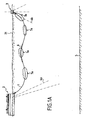
- the double wave arrangement known as a symmetrical "W" ( figure 1a ) which can be made using flexible pipes but also allows the use of steel pipes of large diameter and thickness.
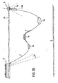
- flexible joints sealed or “flexjoints” are generally installed at each end so as to improve the mechanical decoupling of said floating supports (FPSO and buoy) of said rigid export pipe thick. This provision was implemented on the Girassol field off Angola.
- This configuration requires two anchoring systems associated respectively with the unloading buoy and the submerged intermediate buoy, which generates considerable extra costs due to the multiplication of the number of anchor points and the length of anchor lines especially if the depth of water reaches and exceeds 2000 to 3000 m or more.
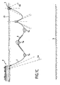
- connection with the FPSO is carried out via a flexible pipe portion, the tension of the simple chain being then taken up by a chain connecting the end of the rigid pipe export to said FPSO.
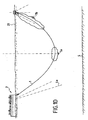
- the curvatures of the rigid pipe are important on the one hand, and on the other hand the relative movements of the floating supports remain mainly absorbed by the variations of curvature of the pipe. in the zones of maximum curvature, these two phenomena being a source of fatigue and a decrease in the service life of the installations, as explained below.
- these configurations are difficult to install.
- Other disadvantages of these different configurations are set forth in the detailed description in connection with the Figures 1a to 1d , below.
- WO 01/96771 which is considered to represent the closest prior art and shows all the features of the preamble of the independent claim 1 discloses a subsurface fluid transport conduit between two floating supports with a rigid pipe whose ends are supported by buoys 3 and 4 which each cooperate with weighting means or suspended dead bodies 32, 33 ( fig.8 ) or which are anchored to the seabed by tensioning links 18, 19 ( fig.1 and 6 ).
- WO 01/96771 therefore describes an assembly, either of the type anchored to the ground ( Fig. 1 , 2 ), either of free type with suspended dead body ( fig.8 , 8b).
- This system is either too stiff (in the case of anchoring the ground on both ends), or too soft (in the case of the suspension of a dead body at each end).
- the installation is either subject to fatigue phenomena, or too unstable. In total, the behavior of this installation is similar to prior art W configuration installations.
- WO 99/62762 also describes a symmetrical installation in which in addition the rigid fluid transport pipe is positioned in a horizontal plane, therefore in quasi-balance of buoyancy, which is also detrimental to withstand the phenomenon of fatigue due to instabilities under the effect of swell and currents.
- WO 2005/090152 speculatively describes several installation systems in which on the one hand there again the rigid central pipe is positioned in a horizontal plane, and on the other hand, the anchors at the ends of said rigid central pipe are almost vertical and do not bring therefore virtually no stability, both vertical and transverse, which makes said rigid pipe extremely sensitive to the phenomenon of fatigue caused by swell and cross currents.
- the problem is to achieve a subsurface-installed export pipe, connecting two floating supports and having increased resistance to the phenomena of fatigue generated mainly by the movements of said floating supports, while remaining of moderate cost and having a great deal of simplicity of installation.
- said rigid pipe is not situated in a horizontal plane between its two ends but has a curvature that is convex if it is situated above its ends, or concave if it is located below, its ends.
- Maintaining a minimum curvature of said rigid pipe makes it possible to avoid vibratory instabilities occurring under the effects of waves and currents, leading to curvature inversions, which would represent a strong variation of stress which would then have the effect of considerably reducing the life of the pipe.
- said end connected by a said tensioning link to one of said two floating supports is not then connected to the seabed and comprises or cooperates with ballasting means and does not involve or cooperate with means of buoyancy, and vice versa
- said end connected to the seabed by a said tensioning link is not connected to the other said floating support by a tensioning link and comprises or cooperates with buoyancy means and does not understand or does not cooperate with ballasting means.
- This asymmetrical configuration at both ends according to the invention offers a good compromise between stability and flexibility of the installation to reduce fatigue phenomena related to waves and currents that can affect the life of the installation.
- an optimal compromise is obtained by varying the angle of inclination of said tensioning links.
- the angle ⁇ 1 , ⁇ 2 between the axis of said rigid pipe at its ends and the horizontal is maintained in absolute value between 2 and 20 °, preferably 5 to 15 °.
- said first end of said rigid pipe is connected to the most stable floating support of said two floating supports.
- most stable floating support is understood to mean the floating support least subject to movements as a function of the agitation of the sea related to the swell or the currents, namely the heavier and / or bulkier floating support. , and / or the one best anchored.
- the floating supports according to the invention may be formed by oilfield platforms or floating vessels, buoys or tanks anchored to the seabed.
- the two floating supports are respectively constituted by a floating support of the FPSO type and an unloading buoy.
- said rigid pipe is connected to its said first end to said floating support type FPSO.
- the minimum radius of curvature of the curve in quasistatic quiescent state (Rm) is greater than four times, preferably ten times the ultimate minimum radius of curvature of the pipe, said radius of curvature ultimate minimum substantially corresponding to a maximum stress in the material constituting the pipe, in particular steel, under the sole effect of the curvature, equal to 66% of the elastic limit of said material.
- the minimum radius of curvature of said central rigid pipe in the form of a chain curve is 750 m, preferably 1500 m.
- the rigid steel pipes have significant curvatures and the distance variations between the floating supports are compensated by the curvature variations of the rigid pipe, in the maximum curvature zone, thus causing variations in important constraint, the combination of these two phenomena resulting in a radical decrease in the life of said rigid pipes as recalled above.
- the minimum radii of curvature are of the order of 1.2 to 2 times the value of the ultimate minimum radius of curvature. It would be theoretically possible to increase these values, but then the relative excursions of the two floating supports relative to each other would be drastically reduced, which goes against the desired objective. Indeed, if in the reduced depths of water, it is possible to anchor by an effective passive (non-dynamic) anchoring method the floating supports to limit the excursions, as soon as the depth of water reaches and exceeds 1000-1500 m, these anchoring systems do not allow to obtain better than +/- 4% of the water height, which then requires on the part of the export pipe, a large excursion capacity .
- the solution proposed by the prior art is either to multiply the number of arches or locally increase the curvature of the pipe.
- the increase in said curvature has the effect of locally increasing the stress, and for small displacements of the floating supports, the variations in radius of curvature causes significant variations in stress, which considerably reduces the fatigue life.
- Another advantage of the invention is to implement a reduced rigid pipe length with respect to the pipes with high curvatures of the prior art, resulting in reduced pressure losses and reduced cost.
- the invention is also particularly advantageous, in particular in that it requires a minimum anchoring at the bottom of the sea and therefore reduced costs, but also it allows a very easy installation in the sea of the device according to the invention, since a laying ship, as will be explained later.
- said tensioning links form with the axes XX ', YY' of said rigid pipe at its ends angles ( ⁇ , ⁇ ) able to vary and vertically move the ends of said rigid pipe, when said floating supports are in motion and the distance between them varies, said angles having values in quasi-static rest state, less than 150 °, preferably less than 100 °.
- the angles ⁇ or ⁇ between said tensioning links and tangents to the ends of the pipe may vary and in particular, in the case where the floating supports move away from each other, increase up to 180 ° (maximum angle) thus providing the excess length necessary for the said movement to have a reduced effect on the efforts of traction or compression at said ends of the rigid pipe and therefore a reduced effect on the variation of the curvature of said rigid pipe and thus still a reduced effect on the variation of stress.
- the arrangement according to the invention makes it possible to have a radius of curvature of the steel pipe of great thickness, very high, that is to say greater than four times, preferably greater than ten times the radius of curvature. ultimate minimum of the pipe, said ultimate minimum radius of curvature substantially corresponding to a maximum stress in the material under the sole effect of the curvature, equal to 66% of the elastic limit of said material.
- the steel pipe could be lightened so as to exactly compensate for its own weight in the water, in order to obtain a rectilinear configuration, that is to say an infinite radius of curvature, but it is preferred so as to avoid vibrations phenomena.
- in the vertical, horizontal or oblique planes maintain the curve in a vertical plane, with a curvature either convex (positive buoyancy) or concave (negative buoyancy).
- the depth at which are positioned the ends of the rigid pipe initially at rest, and the angles of the pipe at its ends are substantially identical to both ends of the rigid pipe.
- said flexible pipes are connected to the ends of said central rigid pipe by flexible mechanical joints, the latter being mechanically connected by a tensioning link, respectively to the floating support and to the anchor point located at the bottom of the sea.
- the flexible pipe providing the connection between the end of the rigid pipe and said floating support preferably the flexible pipe providing the connection with a floating support connected to the seabed by a said tensioning link, preferably another unloading buoy, has an S configuration.
- This embodiment makes it possible to prevent the flexible pipe from interfering with said tensioning link ensuring the anchoring of the end of the rigid pipe to the seabed.
- said rigid pipe comprises buoyancy elements, constituted by a thermal insulation foam distributed all along and all around said pipe, preferably in a substantially uniform and continuous manner to thereby ensure both thermal insulation and buoyancy of said rigid pipe.
- said rigid pipe has a convex curvature seen from the sea surface. It is also possible that said rigid pipe has a concave curvature seen from the surface of the sea. However, it is preferred to implement a rigid pipe having a convex curvature seen from the surface because, in this type of configuration, it appears that the curvature variations of the rigid pipe, and therefore the stresses, are less than in the concave configuration, which improves by the life of said pipe. And, moreover, the installation is facilitated as will be explained further in the detailed description.
- the export pipe 1 is lightened locally by syntactic foam-type buoyancy elements 6 installed around the rigid pipe 1, so as to reverse its curvature, which is then seen from the surface and starting from the FPSO or buoy, successively concave, then convex, then finally concave.
- syntactic foam-type buoyancy elements 6 installed around the rigid pipe 1, so as to reverse its curvature, which is then seen from the surface and starting from the FPSO or buoy, successively concave, then convex, then finally concave.
- two inflection points located respectively on either side of the central lightened area.
- Said reinforcement is either made by a stepwise increase in the thickness of the wall of the pipe, or by the use of conical connecting pieces to obtain a continuous variation of the thickness of said connecting piece.
- variable thickness are very delicate to manufacture, because their length reaches and exceeds 12 to 15 m and their cost, very high when they are made of high-performance steel, becomes exorbitant when they must be made of titanium to achieve the objectives of resistance
- the fatigue zone 7a is in the hollow of the chain and the area requiring a reinforcement 7b close to the unloading buoy 3 must be reinforced by a said conical connecting piece or stepped thickness.
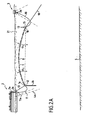
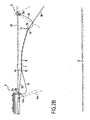
- FIG. 2a the side of the export pipe according to the invention is shown in side view, connecting an FPSO 2 and an unloading buoy 3 consisting of a rigid central pipe 1 in the shape of a simple arch with convex curvature, seen from area.
- Said convex curvature is obtained by lightening the pipe by buoyancy elements 8 in a discontinuous manner.
- a buoyancy with a foam disposed continuously around the pipe also playing the role of thermal insulation, so that the temperature of the transferred crude oil keeps a temperature as high as possible throughout the course, so a viscosity as low as possible, which optimizes the flow in the pipe.
- this insulation and buoyancy foam will advantageously be distributed all along and around the pipe, preferably in a uniform manner.
- the first end 1a of the central export pipe 1 is connected, on the FPSO side 2, to a first mechanical joint 12, to which is connected a first flexible pipe 11 leading to its other end at 11a on a rigid pipe 2a. integral with the edging of said FPSO 2.
- This first flexible pipe 11 preferably has an internal diameter identical to that of the central export pipe 1 and that of the pipe 12c of said first mechanical joint 12 as will be explained below.
- Said first mechanical articulation 12 is connected to the FPSO 2 at an attachment point 2b by means of a mooring tensioning link such as a chain 13, preferably a cable, made of steel or composite material, and supports a weighting means consisting of a heavy chain section 14, for example from 100 to 200 tons, or a dead body of similar weight, while simply above its point of attachment on said first mechanical joint 12 .
- a mooring tensioning link such as a chain 13, preferably a cable, made of steel or composite material, and supports a weighting means consisting of a heavy chain section 14, for example from 100 to 200 tons, or a dead body of similar weight, while simply above its point of attachment on said first mechanical joint 12 .
- the second end 1b of the rigid central pipe 1, unloading buoy side 3, is connected to a second mechanical joint 15, itself connected to a second flexible pipe 16 connected at 3a to the unloading buoy 3.
- a float 17 compensates the apparent weight of the assembly at the end of the rigid pipe 1 and a tensioning and anchoring cable 18 integral with the second mechanical joint 15 is connected at 20a to a suction anchor 20 at the seabed , as shown on the figure 3 .
- two anchoring cables 18 will advantageously be used.
- the two corresponding suction anchors 20 will then be positioned preferably symmetrically with respect to the vertical plane passing substantially through the axes of the FPSO and the unloading buoy.
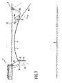
- FIG 6a there is shown a variant of the invention in which the rigid central export pipe 1 is made slightly heavy in the water, by adjusting the vertical thrust upwards created by the buoyancy 8 distributed preferably continuously all the along the pipe, and simultaneously playing the role of thermal insulation, which gives it, seen from the surface, a concave curvature.
- the rigid central export pipe 1 is made slightly heavy in the water, by adjusting the vertical thrust upwards created by the buoyancy 8 distributed preferably continuously all the along the pipe, and simultaneously playing the role of thermal insulation, which gives it, seen from the surface, a concave curvature.
- the second flexible pipe 16 is equipped with floats 16a and the end of the pipe 15c is bent upwards, so that said flexible pipe 16 does not interfere with the anchoring cable 18.
- the float 17 is here incorporated directly into said flexible pipe 16 at 17a, a submerged complementary float 16a associated with not shown curvature limiters, maintaining an acceptable curvature in the upper part of the chain of said flexible pipe 16.
- the weight of the heavy chain 14, the buoyancy of the float 17 are adjusted according to the linear weight of the rigid pipe 1 so that said central rigid pipe 1 adopts a quasi-static state of rest an arch-shaped configuration , preferably in a substantially chain-shaped curve such that the angles ⁇ 1 , ⁇ 2 between the half-lines of the axes XX ', YY' of said rigid pipe and the horizontal half-lines at each of its ends 1a, 1b towards the other end 1b, 1a, are in absolute value less than 20 °, preferably less than 15 °.
- the heavy chain 14 and the float 17 make it possible to arrange the tensioning links 13 and 18 at an angle of respectively ⁇ and ⁇ of at most 150 °, preferably at most 100 °, relative to the axes XX 'and YY' of the ends central rigid pipes 1a and 1b respectively, and thus allow to absorb the relative movements of the floating supports 2 and 3 as explained below.
- the figure 4 is a sectional view of a first mechanical joint 12 of laminated abutment type, comprising a main body 12a having a hollow or a central void, a laminated abutment 12b and an inner tubular 12c connected on its right side to the end 1a of the central export pipe 1, and on its left side to the first flexible pipe 11.
- the main body 12a receives, on its outer surface, the end of the tensioning and mooring link 13 and supports the heavy chain 14.
- the figure 5 is a cross-sectional view of a second mechanical joint 15 of the laminated abutment type, comprising a main body 15a, a laminated abutment 15b and an internal tubing 15c connected on its left side to the other end 1b of the central pipe and on its right side to the second flexible pipe 16.
- the main body 15a receives the end of the tensioning and anchoring cable 18 and is suspended from the float 17, not shown, by a cable 17a.
- the joints 12, 15 are initially installed on the central rigid pipe export 1 during its manufacture aboard the laying ship 22, by direct welding of the pipes 12c, 15c at the ends of said central rigid pipe.
- the second end of said tubes 12c, 15c being equipped with flanges on which is connected the flexible connecting pipes with the FPSO and the unloading buoy.
- the central export pipe is therefore flanged flange continuous, and because of said flanges it is then easy to replace the flexible end pipes, if necessary, during maintenance operations of the installation.
- the laminated abutments 12b and 15b consist of stacks of elastomer layers and metal sheets, preferably of spherical shape, allowing deformations, thus angular variations of the tubular 12c, 15c with respect to the main body 12a, 15a. .
- said manifold can move inside an angle cone at the delta vertex 2, for example here substantially +/- 15 °, while being capable of transmitting considerable compressive forces, which can reach several tens, or even several hundred tons, via the laminated abutment.
- This type of laminated abutment known to those skilled in the art, is manufactured by TECHLAM France and its shape is advantageously substantially spherical, which makes it possible to have a self-centering effect, leading to a better distribution. constraints within said abutment, thereby avoiding the risk of pinching the elastomer layers that can lead to degradation of the performance of the mechanical joint, or even ruin.
- the second mechanical articulation 15 has a laminated abutment 15b as well as articulation functions similar to those of the first mechanical articulation 12, but its shape differs because of the various forces to be balanced, which are radically different from one side to the other. other of said export line 1.
- the minimum radius of curvature Rm in quasi-static state of rest of the assembly is substantially equal to 15.4 times the Rmu, thus much greater than 10 times the Rmu.
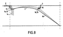
- the necessary excess length is provided mainly by the variation of the angle ⁇ , which corresponds to a slight rise towards the surface of the flexible mechanical articulation 12 and a rotation of the docking link 13 around its point of attachment 2b on the FPSO, in the counter-clockwise direction, as shown in FIG. figure 8 .
- the angle ⁇ increases, the flexible mechanical articulation 15 sinks slightly in a circular arc centered at the anchoring point 20a of the anchoring cable 20, and the end 1b of the rigid pipe-shaped arch connected to said flexible mechanical joint 15 then sinks slightly, as also shown on the figure 8 .
- the two flexible pipes 11 and 16 then undergo significant deformations, but they generate almost no reaction in the system, so no significant constraint.
- the rigid pipe according to the invention thus has a fatigue strength ten times greater than that of the devices of the invention.
- prior art illustrated on the Figures 1a-1d illustrated on the Figures 1a-1d . Indeed, in conventional systems, the spacing and approaching movements of the FPSO and the buoy are absorbed solely by deformation of the rigid pipe forming three arches in the configurations 1a, 1b, 1c, and a single arch in the case of the 1d configuration. These deformations remain significant and the radii of curvature vary over a wide range in the zones 7a, thereby inducing large stress variations between the minimum and maximum values, thereby drastically reducing the fatigue strength of the rigid pipe. export.
- the arch of the export pipe according to the invention achieves a theoretical fatigue life of the order of 10,000 years for standard welding qualities in the offshore field, which can be considered as an almost infinite lifetime, whereas the theoretical fatigue life of conventional systems lead to values of 300 to 500 years, which gives, for these systems according to the prior art, only one 10 to 15 factor of dependability compared to the goal of effective life of facilities that is 25-30 years or more.
- This factor of 10 to 15 is currently considered by oil operators as insufficient to qualify the operational safety of their installation.
- the device according to the invention makes it possible to radically increase this safety factor in proportions of 20 to 30 times, while remaining in the implementation of proven technologies, and reduced costs of prefabrication and installation.
- two arc-shaped rigid pipes 1 are installed in parallel, each of which then has flexible mechanical articulation parts 12 and 15 at the ends, the said joints 12, on the FPSO side, being preferably independent of each other, that is to say that each of the rigid pipes 1 is connected to a clean tie 13 and a clean heavy chain 14.
- the mechanical articulation parts 15 are preferably connected to the same anchoring link 18 and, where appropriate, to the same float 17.
- This configuration saves a suction anchor (30 tons) and an anchor (1500 to 2000 m depending on the water depth), which will not have to be installed at the bottom of the sea.
Landscapes
- Engineering & Computer Science (AREA)
- Mechanical Engineering (AREA)
- Chemical & Material Sciences (AREA)
- Combustion & Propulsion (AREA)
- Ocean & Marine Engineering (AREA)
- General Engineering & Computer Science (AREA)
- Earth Drilling (AREA)
- Rigid Pipes And Flexible Pipes (AREA)
- Laying Of Electric Cables Or Lines Outside (AREA)
- Container, Conveyance, Adherence, Positioning, Of Wafer (AREA)
- Supports For Pipes And Cables (AREA)
Claims (18)
- Vorrichtung für den Fluidtransfer zwischen zwei am Meeresgrund (5) verankerten schwimmenden Trägern (2, 3), umfassend eine starre mittlere, oberflächennah verlegte Unterwasserleitung (1), deren Enden (1a, 1 b) jeweils mittels einer Schlauchleitung (11, 16) mit jeweils einem der beiden Träger verbindbar sind, wobei:a) der durchgehende Teil der starren mittleren Leitung (1) Auftriebselemente (8) umfaßt oder damit zusammenwirkt, so daß die starre mittlere Leitung (1) im quasi-statischen Ruhezustand eine Gestalt in Form eines gekrümmten Bogens annimmt, undb) die Schlauchleitungen (11, 16) Längen und Krümmungen aufweisen, so daß die Krümmungsänderungen der Schlauchleitungen geeignet sind, die Bewegungen der schwimmenden Träger auszugleichen, undc) die starre Leitung an jedem Ende über ein Spannbindeglied (13, 18) entweder mit einem der beiden schwimmenden Träger (2, 3) oder mit dem Meeresgrund verbindbar ist,dadurch gekennzeichnet, daß die Spannbindeglieder (13, 18) an der starren Leitung (1) verbunden sind:- an einem ersten Ende (1a), mit einem schwimmenden Träger (2, 3), wobei das erste Ende (1a) Ballastmittel (14) umfaßt oder damit zusammenwirkt, bzw.- an ihrem zweiten Ende (1 b), mit dem Meeresgrund, wobei das zweite Ende (1b) zusätzliche Auftriebsmittel (17) umfaßt oder damit zusammenwirkt.
- Transfervorrichtung nach Anspruch 1, dadurch gekennzeichnet, daß die starre mittlere Leitung (1) im quasi-statischen Ruhezustand eine Gestalt in Form eines gekrümmten Bogens entlang einer im wesentlichen kettenförmigen Kurve annimmt, welche derart ist, daß die Winkel (α1, α2) zwischen den Halbgeraden der Achsen (XX', YY') der starren Leitung und den horizontalen Halbgeraden an jedem ihrer Enden (1a, 1 b) in Richtung des anderen Endes (1b, 1a) im Absolutwert kleiner als 20°, vorzugsweise kleiner als 15° sind.
- Vorrichtung nach Anspruch 1 oder 2, dadurch gekennzeichnet, daß das erste Ende (1a) der starren Leitung mit dem stabilsten schwimmenden Träger (2) der beiden schwimmenden Träger verbunden ist.
- Vorrichtung nach einem der Ansprüche 1 bis 3, dadurch gekennzeichnet, daß die beiden schwimmenden Träger von einem schwimmenden Träger vom Typ FPSO (2) bzw. von einer Verladeboje (3) gebildet sind.
- Vorrichtung nach einem der Ansprüche 1 bis 3, dadurch gekennzeichnet, daß die starre Leitung an ihrem ersten Ende mit einem schwimmenden Träger vom Typ FPSO (2) verbunden ist.
- Vorrichtung nach einem der Ansprüche 1 bis 5, dadurch gekennzeichnet, daß die Spannbindeglieder (13, 18) mit den Achsen (XX', YY') der starren Leitung an ihren Enden (1 a, 1b) Winkel (β, γ) bilden, die geeignet sind, die Enden (1 a, 1b) der starren Leitung zu verändern und vertikal zu bewegen, wenn die schwimmenden Träger in Bewegung sind, und daß der Abstand zwischen ihnen variiert, wobei die Winkel - wenn die Vorrichtung sich im quasi-statischen Ruhezustand befindet - Werte von unter 150°, vorzugsweise von unter 100 aufweisen.
- Vorrichtung nach einem der Ansprüche 1 bis 6, dadurch gekennzeichnet, daß- die Ballastmittel (14) von einer im Bereich des ersten Endes aufgehängten schweren Kette gebildet sind und- die Auftriebsmittel (17) von einer Boje, an der das zweite Ende aufgehängt ist, gebildet sind.
- Vorrichtung nach einem der Ansprüche 1 bis 7, dadurch gekennzeichnet, daß die Schlauchleitungen (11, 16) mit den Enden der starren mittleren Leitung durch flexible mechanische Gelenke (12, 15) verbunden sind, die umfassen:- einen starren Stutzen (12c, 15c), der an seinen Enden mit den jeweiligen Enden der starren Leitung (1) und der Schlauchleitung (11, 16) verbunden ist, sowie- einen Hauptkörper (12a, 15a), der ein Schmiedeteil bildet, das definiert- eine Außenseite, an der die Spannbindeglieder (13, 18) und gegebenenfalls Ballastmittel (14) oder Auftriebsmittel (17, 16a-17a) eingehakt sind, und- eine Innenseite, die einen von dem Stutzen durchgriffenen hohlen Durchgang begrenzt,- wobei die Innenseite des Hauptkörpers und der Stutzen einen vorzugsweise kugelartigen geschichteten Anschlag (12b, 15b) mit Elastomerschichten, mit einer Rotationsachse (XX', YY') tragen, der die flexible mechanische Verbindung zwischen dem Hauptkörper und dem Stutzen sicherstellt, um Winkelbewegungen des Stutzens gegenüber dem Hauptkörper innerhalb eines Kegels mit Spitzenwinkel, der im wesentlichen auf der Rotationsachse (XX', YY') des geschichteten Anschlags liegt, um einen Spitzenwinkel δ mit einem Maximalwert von 15° zuzulassen.
- Vorrichtung nach einem der Ansprüche 1 bis 8, dadurch gekennzeichnet, daß die Schlauchleitung (16), welche die Verbindung zwischen der starren Leitung (1) und dem schwimmenden Träger (2, 3) sicherstellt, vorzugsweise die Schlauchleitung (16), welche die Verbindung mit einem schwimmenden Träger (3), der über ein Spannbindeglied (18) mit dem Meeresgrund verbunden ist, weiterhin vorzugsweise einer Verladeboje (3) sicherstellt, eine S-förmige Gestalt aufweist.
- Vorrichtung nach Anspruch 9, dadurch gekennzeichnet, daß der Stutzen, der die Verbindung zwischen dem Ende der starren mittleren Leitung und der Schlauchleitung (16) sicherstellt, auf der Seite der flexiblen Verbindung ein nach oben gebogenes Ende (15d) aufweist.
- Vorrichtung nach einem der Ansprüche 1 bis 10, dadurch gekennzeichnet, daß die starre Leitung (1) Auftriebselemente (8) umfaßt, die von einem Wärmeisolierschaum gebildet sind, der entlang der und um die Leitung herum verteilt ist, vorzugsweise im wesentlichen gleichmäßig und kontinuierlich, um auf diese Weise sowohl die Wärmeisolierung als auch die Schwimmfähigkeit der starren Leitung sicherzustellen.
- Vorrichtung nach einem der Ansprüche 1 bis 11, dadurch gekennzeichnet, daß die starre Leitung (1) von der Meeresoberfläche (21) aus gesehen eine konvexe Krümmung aufweist.
- Vorrichtung nach einem der Ansprüche 1 bis 11, dadurch gekennzeichnet, daß die starre Leitung (1) von der Meeresoberfläche (21) aus gesehen eine konkave Krümmung aufweist.
- Vorrichtung nach einem der Ansprüche 1 bis 13, dadurch gekennzeichnet, daß der Winkel (α1, α2) zwischen der Achse der starren Leitung an ihren Enden und der Horizontalen im Absolutwert zwischen 2 und 20°, vorzugsweise 5 und 15° gehalten ist.
- Vorrichtung nach einem der Ansprüche 1 bis 14, dadurch gekennzeichnet, daß der minimale Krümmungsradius der starren mittleren, kettenkurvenförmigen Leitung 750 m, vorzugsweise 1500 m beträgt.
- Vorrichtung nach Anspruch 8, dadurch gekennzeichnet, daß sie zwei solch bogenförmige starre Leitungen (1) umfaßt, die parallel zueinander angeordnet sind.
- Verfahren zum Installieren einer Vorrichtung nach einem der Ansprüche 1 bis 15, von einem an der Oberfläche befindlichen Verlegeschiff (22) aus im Meer, dadurch gekennzeichnet, daß es die folgenden aufeinanderfolgenden Schritte umfaßt:1) am Meeresgrund oder gegebenenfalls an einem ersten schwimmenden Träger, vorzugsweise einer Verladeboje (3), wird ein Spannbindeglied (18) festgehakt,2) die starre mittlere Leitung (1) wird durch Verbinden von Leitungseinzelelementen, die Auftriebselemente (8) umfassen oder damit zusammenwirken, zusammengesetzt und im Meer verlegt, wobei das erste Leitungseinzelelement am Ende des Spannbindegliedes (18) eingehakt worden ist,3) ein weiteres Spannbindeglied (13) wird am Ende (1 b) des letzten Leitungselements, dann an einem zweiten schwimmenden Träger (2) oder gegebenenfalls am Meeresgrund festgehakt,4) die Ballastmittel (14) und die Auftriebsmittel (17) werden an den Enden (1a, 1b) der starren Leitung angebracht, anschließend5) werden die Schlauchleitungen (11, 16) zwischen den schwimmenden Trägern (2, 3) und dem ersten und dem zweiten Ende (1 a, 1 b) der starren Leitung angebracht.
- Verfahren nach Anspruch 17, dadurch gekennzeichnet, daß:- bei Schritt 1) das Spannbindeglied (18) am Meeresgrund auf der Seite des am wenigsten stabilen schwimmenden Trägers, vorzugsweise einer Verladeboje (3) festgehakt wird und- bei Schritt 3) das weitere Spannbindeglied (13) an dem stabilsten schwimmenden Träger, vorzugsweise vom Typ FPSO (2) festgehakt wird.
Applications Claiming Priority (2)
| Application Number | Priority Date | Filing Date | Title |
|---|---|---|---|
| FR0504848A FR2885613B1 (fr) | 2005-05-13 | 2005-05-13 | Dispositif de transfert de fluide entre deux supports flottants |
| PCT/FR2006/001053 WO2006120351A1 (fr) | 2005-05-13 | 2006-05-11 | Dispositif de transfert de fluide entre deux supports flottants |
Publications (2)
| Publication Number | Publication Date |
|---|---|
| EP1899219A1 EP1899219A1 (de) | 2008-03-19 |
| EP1899219B1 true EP1899219B1 (de) | 2012-02-15 |
Family
ID=35482304
Family Applications (1)
| Application Number | Title | Priority Date | Filing Date |
|---|---|---|---|
| EP06764599A Active EP1899219B1 (de) | 2005-05-13 | 2006-05-11 | Vorrichtung zur übergabe von fluiden zwischen zwei schwemmenden plattformen |
Country Status (6)
| Country | Link |
|---|---|
| US (1) | US7677837B2 (de) |
| EP (1) | EP1899219B1 (de) |
| AT (1) | ATE545578T1 (de) |
| BR (1) | BRPI0610281B1 (de) |
| FR (1) | FR2885613B1 (de) |
| WO (1) | WO2006120351A1 (de) |
Families Citing this family (17)
| Publication number | Priority date | Publication date | Assignee | Title |
|---|---|---|---|---|
| WO2005090152A1 (en) * | 2004-03-23 | 2005-09-29 | Single Buoy Moorings Inc. | Field development with centralised power generation unit |
| FR2921994B1 (fr) * | 2007-10-03 | 2010-03-12 | Technip France | Methode d'installation d'une conduite tubulaire sous-marine |
| BRPI0907636A2 (pt) | 2008-01-28 | 2015-07-21 | Single Buoy Moorings | Sistema de transferência de hidrocarbonetos, e, estrutura para hidrocarbonetos |
| EP2291577A1 (de) * | 2008-04-09 | 2011-03-09 | Amog Pty Ltd | Steigrohrstütze |
| GB2472644A (en) * | 2009-08-14 | 2011-02-16 | Acergy France Sa | Marine riser apparatus and method of installation |
| WO2011150363A1 (en) * | 2010-05-28 | 2011-12-01 | Weatherford/Lamb, Inc. | Deepwater completion installation and intervention system |
| NO335242B1 (no) | 2010-09-01 | 2014-10-27 | Aker Pusnes As | Lasteslange |
| KR101751829B1 (ko) * | 2010-11-23 | 2017-06-29 | 대우조선해양 주식회사 | 유체이송장치 |
| KR200478733Y1 (ko) * | 2010-12-20 | 2015-11-11 | 대우조선해양 주식회사 | 유체 이송 시스템 |
| FR2973473B1 (fr) | 2011-03-29 | 2014-06-13 | Saipem Sa | Materiau d'isolation thermique et/ou de flottabilite rigide pour conduite sous-marine |
| FR2997747B1 (fr) * | 2012-11-08 | 2015-01-16 | Technip France | Conduite flexible de transport d'un fluide cryogenique, installation et procede associes |
| US9499249B2 (en) | 2014-01-15 | 2016-11-22 | Steven Clary Bowhay | Pumping system for transporting fresh water in a seawater environment |
| US11878774B2 (en) | 2017-09-06 | 2024-01-23 | Econnect Energy As | Tie-in system and fluid transfer system comprising such a tie-in system |
| CN111692429A (zh) * | 2020-05-19 | 2020-09-22 | 中交第四航务工程局有限公司 | 一种大直径hdpe管道水下合龙方法 |
| CN115535156B (zh) * | 2022-10-18 | 2025-04-25 | 中船黄埔文冲船舶有限公司 | 一种海补管偏向浮力装置及其使用方法 |
| CN116717725B (zh) * | 2023-05-29 | 2024-02-20 | 广东工业大学 | 一种海面输油管路 |
| CN120159428B (zh) * | 2025-05-19 | 2025-09-09 | 杭州邦维流体技术有限公司 | 基于无轴螺旋输运的可调柔性管技术的稀土采集系统 |
Family Cites Families (15)
| Publication number | Priority date | Publication date | Assignee | Title |
|---|---|---|---|---|
| US3466680A (en) * | 1967-07-14 | 1969-09-16 | Air Logistics Corp | Apparatus for loading and unloading offshore vessels |
| US4183697A (en) * | 1976-01-27 | 1980-01-15 | Compagnie Generale Pour Les Developpements Operationnels Des Richesses Sous-Marines "C.G. Doris" | Laying of underwater pipelines |
| FR2386757B1 (de) * | 1977-04-04 | 1983-02-04 | Inst Francais Du Petrole | |
| US5505560A (en) * | 1993-10-26 | 1996-04-09 | Offshore Energie Development Corporation (Oecd) | Fluid transfer system for an offshore moored floating unit |
| US5480264A (en) * | 1994-09-07 | 1996-01-02 | Imodco, Inc. | Offshore pipeline system |
| US5944448A (en) * | 1996-12-18 | 1999-08-31 | Brovig Offshore Asa | Oil field installation with mooring and flowline system |
| ID27827A (id) * | 1998-05-29 | 2001-04-26 | Single Buoy Moorings | Sistem pipa transfer |
| FR2807814B1 (fr) * | 2000-04-17 | 2002-07-12 | Techlam | Dispositif de connexion d'une ligne immergee de transport de fluide |
| FR2808263B1 (fr) | 2000-04-28 | 2002-07-05 | Coflexip | Dispositif de transfert d'un fluide entre au moins deux supports flottants |
| NO20003047D0 (no) * | 2000-06-14 | 2000-06-14 | Umoe Anchor Contracting As | FremgangsmÕte ved tilveiebringelse av en rørledningsforbindelse mellom to steder i sjøen, og en transportanordning innbefattende en rørledningsforbindelse mellom to steder i sjøen |
| US6415828B1 (en) * | 2000-07-27 | 2002-07-09 | Fmc Technologies, Inc. | Dual buoy single point mooring and fluid transfer system |
| US6558215B1 (en) * | 2002-01-30 | 2003-05-06 | Fmc Technologies, Inc. | Flowline termination buoy with counterweight for a single point mooring and fluid transfer system |
| GB2390351B (en) * | 2002-07-02 | 2005-05-25 | Bluewater Terminal Systems Nv | Fluid transfer apparatus |
| US7416366B2 (en) * | 2003-01-30 | 2008-08-26 | Single Buoy Moorings Inc. | Subsea pipeline system |
| WO2005090152A1 (en) * | 2004-03-23 | 2005-09-29 | Single Buoy Moorings Inc. | Field development with centralised power generation unit |
-
2005
- 2005-05-13 FR FR0504848A patent/FR2885613B1/fr not_active Expired - Fee Related
-
2006
- 2006-05-11 EP EP06764599A patent/EP1899219B1/de active Active
- 2006-05-11 AT AT06764599T patent/ATE545578T1/de active
- 2006-05-11 BR BRPI0610281-6A patent/BRPI0610281B1/pt not_active IP Right Cessation
- 2006-05-11 US US11/919,765 patent/US7677837B2/en active Active
- 2006-05-11 WO PCT/FR2006/001053 patent/WO2006120351A1/fr not_active Ceased
Also Published As
| Publication number | Publication date |
|---|---|
| BRPI0610281A2 (pt) | 2010-06-08 |
| WO2006120351A1 (fr) | 2006-11-16 |
| US20090097923A1 (en) | 2009-04-16 |
| FR2885613A1 (fr) | 2006-11-17 |
| ATE545578T1 (de) | 2012-03-15 |
| FR2885613B1 (fr) | 2010-07-30 |
| US7677837B2 (en) | 2010-03-16 |
| BRPI0610281B1 (pt) | 2020-05-12 |
| EP1899219A1 (de) | 2008-03-19 |
Similar Documents
| Publication | Publication Date | Title |
|---|---|---|
| EP1899219B1 (de) | Vorrichtung zur übergabe von fluiden zwischen zwei schwemmenden plattformen | |
| EP2286056B1 (de) | Boden-oberfläche-verbindung aus einem starren steigrohr mit flexiblem kanal mit positiver flotation | |
| EP1073823B1 (de) | Verfahren und vorrichtung zur bildung einer verbindung zwischen meeresgrund und oberfläche mittels einer in grosser tiefe installierten unterwasserleitung | |
| EP1078144B1 (de) | Hybridrohrleitung für grosse tiefen | |
| EP2844820B1 (de) | Installation mit meeresboden-zu-oberfläche-verbindungen vom typ eines multi-riser-hybridturms mit flexiblen rohren mit positivem auftrieb | |
| WO1998041729A1 (fr) | Dispositif limiteur de courbure d'une conduite flexible | |
| EP2268887B1 (de) | Trägheitsübergangsrohrelement, insbesondere zur fixierung eines starren unterwasserrohrs | |
| EP2401468B1 (de) | Meeresgrund-oberflächen-verbindungsinstallation der mehrfachsteigrohrhybridturmart mit gleitenden auftriebsmodulen | |
| EP2785952B1 (de) | Vorrichtung für flexible und mannigfaltige verbindungen zwischen meeresgrund und oberfläche auf mindestens zwei ebenen | |
| EP1651840B1 (de) | Vorrichtung zur bildung einer verbindung zwischen meeresgrund und oberfläche, mit biegsamer dichtung zwischen einem steigrohr und einem schwimmer | |
| EP1194677B1 (de) | Verbindungsvorrichtung zwischen boden und oberfläche, mit einer mit mindestens einem schwimmer befestigten unterwasserleitung | |
| EP2148974B1 (de) | Boden-oberflächen-verknüpfungsausrüstung mit einem flexiblen link zwischen einem schwimmenden träger und dem oberen ende eines unterwasserrohrs | |
| EP1917416A1 (de) | Anlage mit mindestens zwei meeresbodenflächensteckern für mindestens zwei auf dem meeresboden liegende unterwasserpipelines | |
| EP2571753B1 (de) | Vorrichtung für eine verbindung zwischen meeresgrund und oberfläche mit einer flexiblen rohrführungsstruktur | |
| WO2014184480A1 (fr) | Dispositif d'ancrage d'un support de goulottes d'une installation fond-surface | |
| OA16986A (fr) | Installation de liaisons fond-surface flexibles multiples sur au moins deux niveaux. | |
| OA17101A (en) | Installation de liaisons fond-surface de type tour hybride multi-risers comprenant des conduites flexibles à flottabilité positive. |
Legal Events
| Date | Code | Title | Description |
|---|---|---|---|
| PUAI | Public reference made under article 153(3) epc to a published international application that has entered the european phase |
Free format text: ORIGINAL CODE: 0009012 |
|
| 17P | Request for examination filed |
Effective date: 20071031 |
|
| AK | Designated contracting states |
Kind code of ref document: A1 Designated state(s): AT BE BG CH CY CZ DE DK EE ES FI FR GB GR HU IE IS IT LI LT LU LV MC NL PL PT RO SE SI SK TR |
|
| DAX | Request for extension of the european patent (deleted) | ||
| GRAP | Despatch of communication of intention to grant a patent |
Free format text: ORIGINAL CODE: EPIDOSNIGR1 |
|
| GRAS | Grant fee paid |
Free format text: ORIGINAL CODE: EPIDOSNIGR3 |
|
| 17Q | First examination report despatched |
Effective date: 20111116 |
|
| GRAA | (expected) grant |
Free format text: ORIGINAL CODE: 0009210 |
|
| AK | Designated contracting states |
Kind code of ref document: B1 Designated state(s): AT BE BG CH CY CZ DE DK EE ES FI FR GB GR HU IE IS IT LI LT LU LV MC NL PL PT RO SE SI SK TR |
|
| REG | Reference to a national code |
Ref country code: GB Ref legal event code: FG4D Free format text: NOT ENGLISH Ref country code: CH Ref legal event code: EP |
|
| REG | Reference to a national code |
Ref country code: IE Ref legal event code: FG4D Free format text: LANGUAGE OF EP DOCUMENT: FRENCH |
|
| REG | Reference to a national code |
Ref country code: AT Ref legal event code: REF Ref document number: 545578 Country of ref document: AT Kind code of ref document: T Effective date: 20120315 |
|
| REG | Reference to a national code |
Ref country code: DE Ref legal event code: R096 Ref document number: 602006027642 Country of ref document: DE Effective date: 20120405 |
|
| REG | Reference to a national code |
Ref country code: NL Ref legal event code: T3 |
|
| LTIE | Lt: invalidation of european patent or patent extension |
Effective date: 20120215 |
|
| PG25 | Lapsed in a contracting state [announced via postgrant information from national office to epo] |
Ref country code: IS Free format text: LAPSE BECAUSE OF FAILURE TO SUBMIT A TRANSLATION OF THE DESCRIPTION OR TO PAY THE FEE WITHIN THE PRESCRIBED TIME-LIMIT Effective date: 20120615 Ref country code: LT Free format text: LAPSE BECAUSE OF FAILURE TO SUBMIT A TRANSLATION OF THE DESCRIPTION OR TO PAY THE FEE WITHIN THE PRESCRIBED TIME-LIMIT Effective date: 20120215 |
|
| PG25 | Lapsed in a contracting state [announced via postgrant information from national office to epo] |
Ref country code: PL Free format text: LAPSE BECAUSE OF FAILURE TO SUBMIT A TRANSLATION OF THE DESCRIPTION OR TO PAY THE FEE WITHIN THE PRESCRIBED TIME-LIMIT Effective date: 20120215 Ref country code: FI Free format text: LAPSE BECAUSE OF FAILURE TO SUBMIT A TRANSLATION OF THE DESCRIPTION OR TO PAY THE FEE WITHIN THE PRESCRIBED TIME-LIMIT Effective date: 20120215 Ref country code: LV Free format text: LAPSE BECAUSE OF FAILURE TO SUBMIT A TRANSLATION OF THE DESCRIPTION OR TO PAY THE FEE WITHIN THE PRESCRIBED TIME-LIMIT Effective date: 20120215 Ref country code: PT Free format text: LAPSE BECAUSE OF FAILURE TO SUBMIT A TRANSLATION OF THE DESCRIPTION OR TO PAY THE FEE WITHIN THE PRESCRIBED TIME-LIMIT Effective date: 20120615 Ref country code: GR Free format text: LAPSE BECAUSE OF FAILURE TO SUBMIT A TRANSLATION OF THE DESCRIPTION OR TO PAY THE FEE WITHIN THE PRESCRIBED TIME-LIMIT Effective date: 20120516 |
|
| REG | Reference to a national code |
Ref country code: IE Ref legal event code: FD4D |
|
| REG | Reference to a national code |
Ref country code: AT Ref legal event code: MK05 Ref document number: 545578 Country of ref document: AT Kind code of ref document: T Effective date: 20120215 |
|
| PG25 | Lapsed in a contracting state [announced via postgrant information from national office to epo] |
Ref country code: CY Free format text: LAPSE BECAUSE OF FAILURE TO SUBMIT A TRANSLATION OF THE DESCRIPTION OR TO PAY THE FEE WITHIN THE PRESCRIBED TIME-LIMIT Effective date: 20120215 |
|
| PG25 | Lapsed in a contracting state [announced via postgrant information from national office to epo] |
Ref country code: SI Free format text: LAPSE BECAUSE OF FAILURE TO SUBMIT A TRANSLATION OF THE DESCRIPTION OR TO PAY THE FEE WITHIN THE PRESCRIBED TIME-LIMIT Effective date: 20120215 Ref country code: DK Free format text: LAPSE BECAUSE OF FAILURE TO SUBMIT A TRANSLATION OF THE DESCRIPTION OR TO PAY THE FEE WITHIN THE PRESCRIBED TIME-LIMIT Effective date: 20120215 Ref country code: IE Free format text: LAPSE BECAUSE OF FAILURE TO SUBMIT A TRANSLATION OF THE DESCRIPTION OR TO PAY THE FEE WITHIN THE PRESCRIBED TIME-LIMIT Effective date: 20120215 Ref country code: CZ Free format text: LAPSE BECAUSE OF FAILURE TO SUBMIT A TRANSLATION OF THE DESCRIPTION OR TO PAY THE FEE WITHIN THE PRESCRIBED TIME-LIMIT Effective date: 20120215 Ref country code: RO Free format text: LAPSE BECAUSE OF FAILURE TO SUBMIT A TRANSLATION OF THE DESCRIPTION OR TO PAY THE FEE WITHIN THE PRESCRIBED TIME-LIMIT Effective date: 20120215 Ref country code: SE Free format text: LAPSE BECAUSE OF FAILURE TO SUBMIT A TRANSLATION OF THE DESCRIPTION OR TO PAY THE FEE WITHIN THE PRESCRIBED TIME-LIMIT Effective date: 20120215 Ref country code: EE Free format text: LAPSE BECAUSE OF FAILURE TO SUBMIT A TRANSLATION OF THE DESCRIPTION OR TO PAY THE FEE WITHIN THE PRESCRIBED TIME-LIMIT Effective date: 20120215 |
|
| BERE | Be: lapsed |
Owner name: SAIPEM S.A. Effective date: 20120531 |
|
| PG25 | Lapsed in a contracting state [announced via postgrant information from national office to epo] |
Ref country code: IT Free format text: LAPSE BECAUSE OF FAILURE TO SUBMIT A TRANSLATION OF THE DESCRIPTION OR TO PAY THE FEE WITHIN THE PRESCRIBED TIME-LIMIT Effective date: 20120215 Ref country code: SK Free format text: LAPSE BECAUSE OF FAILURE TO SUBMIT A TRANSLATION OF THE DESCRIPTION OR TO PAY THE FEE WITHIN THE PRESCRIBED TIME-LIMIT Effective date: 20120215 |
|
| PLBE | No opposition filed within time limit |
Free format text: ORIGINAL CODE: 0009261 |
|
| STAA | Information on the status of an ep patent application or granted ep patent |
Free format text: STATUS: NO OPPOSITION FILED WITHIN TIME LIMIT |
|
| PG25 | Lapsed in a contracting state [announced via postgrant information from national office to epo] |
Ref country code: MC Free format text: LAPSE BECAUSE OF NON-PAYMENT OF DUE FEES Effective date: 20120531 |
|
| REG | Reference to a national code |
Ref country code: CH Ref legal event code: PL |
|
| 26N | No opposition filed |
Effective date: 20121116 |
|
| PG25 | Lapsed in a contracting state [announced via postgrant information from national office to epo] |
Ref country code: CH Free format text: LAPSE BECAUSE OF NON-PAYMENT OF DUE FEES Effective date: 20120531 Ref country code: LI Free format text: LAPSE BECAUSE OF NON-PAYMENT OF DUE FEES Effective date: 20120531 Ref country code: AT Free format text: LAPSE BECAUSE OF FAILURE TO SUBMIT A TRANSLATION OF THE DESCRIPTION OR TO PAY THE FEE WITHIN THE PRESCRIBED TIME-LIMIT Effective date: 20120215 |
|
| PG25 | Lapsed in a contracting state [announced via postgrant information from national office to epo] |
Ref country code: BE Free format text: LAPSE BECAUSE OF NON-PAYMENT OF DUE FEES Effective date: 20120531 |
|
| REG | Reference to a national code |
Ref country code: DE Ref legal event code: R097 Ref document number: 602006027642 Country of ref document: DE Effective date: 20121116 Ref country code: DE Ref legal event code: R119 Ref document number: 602006027642 Country of ref document: DE Effective date: 20121201 |
|
| PG25 | Lapsed in a contracting state [announced via postgrant information from national office to epo] |
Ref country code: ES Free format text: LAPSE BECAUSE OF FAILURE TO SUBMIT A TRANSLATION OF THE DESCRIPTION OR TO PAY THE FEE WITHIN THE PRESCRIBED TIME-LIMIT Effective date: 20120526 |
|
| PG25 | Lapsed in a contracting state [announced via postgrant information from national office to epo] |
Ref country code: DE Free format text: LAPSE BECAUSE OF NON-PAYMENT OF DUE FEES Effective date: 20121201 |
|
| PG25 | Lapsed in a contracting state [announced via postgrant information from national office to epo] |
Ref country code: BG Free format text: LAPSE BECAUSE OF FAILURE TO SUBMIT A TRANSLATION OF THE DESCRIPTION OR TO PAY THE FEE WITHIN THE PRESCRIBED TIME-LIMIT Effective date: 20120515 |
|
| PG25 | Lapsed in a contracting state [announced via postgrant information from national office to epo] |
Ref country code: TR Free format text: LAPSE BECAUSE OF FAILURE TO SUBMIT A TRANSLATION OF THE DESCRIPTION OR TO PAY THE FEE WITHIN THE PRESCRIBED TIME-LIMIT Effective date: 20120215 |
|
| PG25 | Lapsed in a contracting state [announced via postgrant information from national office to epo] |
Ref country code: LU Free format text: LAPSE BECAUSE OF NON-PAYMENT OF DUE FEES Effective date: 20120511 |
|
| PG25 | Lapsed in a contracting state [announced via postgrant information from national office to epo] |
Ref country code: HU Free format text: LAPSE BECAUSE OF FAILURE TO SUBMIT A TRANSLATION OF THE DESCRIPTION OR TO PAY THE FEE WITHIN THE PRESCRIBED TIME-LIMIT Effective date: 20060511 |
|
| REG | Reference to a national code |
Ref country code: FR Ref legal event code: PLFP Year of fee payment: 11 |
|
| REG | Reference to a national code |
Ref country code: FR Ref legal event code: PLFP Year of fee payment: 12 |
|
| REG | Reference to a national code |
Ref country code: FR Ref legal event code: PLFP Year of fee payment: 13 |
|
| P01 | Opt-out of the competence of the unified patent court (upc) registered |
Effective date: 20230517 |
|
| PGFP | Annual fee paid to national office [announced via postgrant information from national office to epo] |
Ref country code: NL Payment date: 20250429 Year of fee payment: 20 |
|
| PGFP | Annual fee paid to national office [announced via postgrant information from national office to epo] |
Ref country code: GB Payment date: 20250521 Year of fee payment: 20 |
|
| PGFP | Annual fee paid to national office [announced via postgrant information from national office to epo] |
Ref country code: FR Payment date: 20250520 Year of fee payment: 20 |