EP1899522B1 - Machine a laver le linge - Google Patents
Machine a laver le linge Download PDFInfo
- Publication number
- EP1899522B1 EP1899522B1 EP06757485A EP06757485A EP1899522B1 EP 1899522 B1 EP1899522 B1 EP 1899522B1 EP 06757485 A EP06757485 A EP 06757485A EP 06757485 A EP06757485 A EP 06757485A EP 1899522 B1 EP1899522 B1 EP 1899522B1
- Authority
- EP
- European Patent Office
- Prior art keywords
- water
- laundry machine
- steam
- drum
- machine according
- Prior art date
- Legal status (The legal status is an assumption and is not a legal conclusion. Google has not performed a legal analysis and makes no representation as to the accuracy of the status listed.)
- Revoked
Links
- XLYOFNOQVPJJNP-UHFFFAOYSA-N water Substances O XLYOFNOQVPJJNP-UHFFFAOYSA-N 0.000 claims abstract description 325
- 238000005406 washing Methods 0.000 claims abstract description 101
- 238000001514 detection method Methods 0.000 claims description 28
- 238000000034 method Methods 0.000 claims description 19
- 238000003860 storage Methods 0.000 claims description 16
- 239000008400 supply water Substances 0.000 claims description 15
- 238000002347 injection Methods 0.000 claims description 12
- 239000007924 injection Substances 0.000 claims description 12
- 238000001035 drying Methods 0.000 description 12
- 238000010276 construction Methods 0.000 description 6
- 238000010438 heat treatment Methods 0.000 description 4
- 238000004519 manufacturing process Methods 0.000 description 4
- 230000001954 sterilising effect Effects 0.000 description 4
- 238000005086 pumping Methods 0.000 description 3
- 238000010981 drying operation Methods 0.000 description 2
- 230000000694 effects Effects 0.000 description 2
- 230000007257 malfunction Effects 0.000 description 2
- 238000013021 overheating Methods 0.000 description 2
- 238000004659 sterilization and disinfection Methods 0.000 description 2
- 238000009736 wetting Methods 0.000 description 2
- 238000010793 Steam injection (oil industry) Methods 0.000 description 1
- 238000004140 cleaning Methods 0.000 description 1
- 239000000356 contaminant Substances 0.000 description 1
- 239000003599 detergent Substances 0.000 description 1
- 238000009826 distribution Methods 0.000 description 1
- 230000020169 heat generation Effects 0.000 description 1
- 239000007769 metal material Substances 0.000 description 1
- 238000002791 soaking Methods 0.000 description 1
- 239000000243 solution Substances 0.000 description 1
- 238000005507 spraying Methods 0.000 description 1
- 238000010025 steaming Methods 0.000 description 1
- 230000037303 wrinkles Effects 0.000 description 1
Images


Classifications
-
- D—TEXTILES; PAPER
- D06—TREATMENT OF TEXTILES OR THE LIKE; LAUNDERING; FLEXIBLE MATERIALS NOT OTHERWISE PROVIDED FOR
- D06F—LAUNDERING, DRYING, IRONING, PRESSING OR FOLDING TEXTILE ARTICLES
- D06F39/00—Details of washing machines not specific to a single type of machines covered by groups D06F9/00 - D06F27/00
- D06F39/40—Steam generating arrangements
-
- D—TEXTILES; PAPER
- D06—TREATMENT OF TEXTILES OR THE LIKE; LAUNDERING; FLEXIBLE MATERIALS NOT OTHERWISE PROVIDED FOR
- D06F—LAUNDERING, DRYING, IRONING, PRESSING OR FOLDING TEXTILE ARTICLES
- D06F33/00—Control of operations performed in washing machines or washer-dryers
- D06F33/30—Control of washing machines characterised by the purpose or target of the control
- D06F33/47—Responding to irregular working conditions, e.g. malfunctioning of pumps
-
- D—TEXTILES; PAPER
- D06—TREATMENT OF TEXTILES OR THE LIKE; LAUNDERING; FLEXIBLE MATERIALS NOT OTHERWISE PROVIDED FOR
- D06F—LAUNDERING, DRYING, IRONING, PRESSING OR FOLDING TEXTILE ARTICLES
- D06F37/00—Details specific to washing machines covered by groups D06F21/00 - D06F25/00
- D06F37/42—Safety arrangements, e.g. for stopping rotation of the receptacle upon opening of the casing door
-
- D—TEXTILES; PAPER
- D06—TREATMENT OF TEXTILES OR THE LIKE; LAUNDERING; FLEXIBLE MATERIALS NOT OTHERWISE PROVIDED FOR
- D06F—LAUNDERING, DRYING, IRONING, PRESSING OR FOLDING TEXTILE ARTICLES
- D06F39/00—Details of washing machines not specific to a single type of machines covered by groups D06F9/00 - D06F27/00
- D06F39/08—Liquid supply or discharge arrangements
Definitions
- the present invention relates to a laundry machine, and more particularly, to a novel-structure laundry machine that is capable of washing laundry using steam.
- laundry machines are classified into a vertical type laundry machine, a drum of which is mounted in a vertical direction, and a horizontal type laundry machine, the drum of which is mounted in a horizontal direction.
- a typical example of the vertical type laundry machine is a pulsator type washing machine
- a typical example of the horizontal type laundry machine is a drum type washing machine.
- laundry machines do not merely refer to machines that are capable of washing laundry but may include a drying machine that is capable of drying the laundry.
- FIGs. 1 and 2 schematically illustrate the structure of a conventional drum type washing machine.
- the drum type washing machine includes a machine body 10, a tub 20 mounted in the machine body 10, a drum 30 rotatably mounted in the tub 20, and a driving unit for driving the drum 30.
- a laundry inlet hole 11 At the front part of the machine body 10 is formed a laundry inlet hole 11, through which laundry is put into the drum.
- a door 40 is mounted to the machine body adjacen t to the laundry inlet hole 11 for opening and closing the laundry inlet hole.
- dampers 21 At opposite sides of the bottom of the outer circumference of the tub 20 are mounted dampers 21, which support the tub 20 in the machine body 10.
- washing water heater 60 for heating washing water, by which the temperature of the washing water used to wash laundry can be controlled.
- the drum 30 is rotatably mounted in the tub 20. At the circumference of the drum 30 are formed a plurality of through-holes 31, through which washing water is introduced into or discharged from the drum.
- the driving unit includes a driving motor 71 for driving the drum 30, and a belt 72 for transmitting the driving force of the driving motor 71 to the drum 30.
- a washing operation, a rinsing operation, and a spin-drying operation is automatically carried out for a predetermined period of time according to a control signal from a controller (not shown) while laundry and a predetermined amount of detergent are received in the drum 30, whereby the laundry is washed.
- the washing water supplied into the tub is heated by the washing water heater, and then a laundry sterilizing process is carried out using the heated washing water As a result, the power consumption is also unnecessarily large.
- the conventional steam supply unit has the following problems since an amount of washing water necessary to generate steam is automatically supplied.
- an additional water supply valve and an additional water supply channel are needed to supply water to the steam supply unit.
- This problem is caused because a user cannot recognize the amount of washing water supplied to the steam supply unit.
- the conventional steam supply unit is constructed such that the steam is injected into the drum from the top part of the drum.
- drying machine having the steam supply unit in addition to the washing machine having the steam supply unit.
- This drying machine not only dries laundry but also supplies the steam to wrinkled dry laundry, thereby accomplishing sterilization of the laundry and removal of wrinkles from the laundry.
- EP 1 469 120 A1 describes a washing method and a steam injection type washing machine, wherein the washing machine includes a steam supply unit, which receives water via a water tap and which generates steam in a steam generator.
- EP 1 441 060 A1 describes a dryer having an apparatus for spraying some further components onto the laundry.
- EP 1 507 031 A1 describes a heating apparatus of a washing machine and a control method thereof, wherein the washing machine includes a steam generator providing steam to the drum of the washing machine, wherein the water is supplied to the steam generator via a water supply tube, which is formed at one side of the upper container.
- the present invention has been made in view of the above problems, and it is an object of the present invention to provide a novel-structure laundry machine in which a structure to supply water to a steam supply unit is improved, whereby the recognition of the amount of water supplied by a user is possible.
- the laundry machine may further comprise: a tub for storing washing water, the tub having the drum rotatably mounted therein.
- the primary steam supply pipe may communicate with the interior of the tub through a predetermined position of the lower circumference of the tub such that the steam can be supplied into the drum through the tub.
- the steam moves to the upper part of the drum from the lower part of the drum. This is because the steam is lighter than air. Consequently, once the steam is supplied to the lower part of the drum, the steam moves upward.
- the tub may be provided at the lower part thereof with a storage part, which protrudes outward, the storage part having a heater for heating the washing water mounted therein.
- the predetermined position of the tub through which the primary steam supply pipe extends be lower than the bottom of the drum but be higher than the position where the heater is mounted.
- the steam supply unit may include: a case for storing the water for steam generation therein, the case being constructed to receive the water for steam generation through the water inlet port; and a heater for heating the water for steam generation.
- the case may be disposed at the inside upper end of the machine body.
- the case may be received in the machine body in a drawer-type inserting fashion through the front part of the machine body.
- the case may be disposed in the upper part of the drum or the tub. Al-ternatively, the case may be located approximately at a lower position than the middle part of the machine body in the machine body. Of course, the case may be located approximately at a lower position than the bottom of the drum.
- the laundry machine further comprise a water inlet pipe:
- the water inlet pipe has one end communicating with the water inlet port and the other end communicating with the case such that water for steam generation is supplied to the case from the water inlet port.
- the water inlet port selectively communicate with the outside through a cover part.
- the case is provided with an overflow pipe for allowing oversupplied water to overflow therethrough.
- one end of the overflow pipe communicates with the case at the position of the case corresponding to the oversupplied water level, and the other end of the overflow pipe communicates with at least one of the drum, the tub, and a water drainage pipe for draining the water from the tub.
- the laundry machine further comprise a water level detection part for detecting the water level of water received in the case.
- the heater be controlled based on the water level detected by the water level detection part.
- the water level detection part may include an electrode sensor having at least two electrodes.
- the laundry machine further comprise a water level display part for informing a user of the information detected by the water level detection part.
- the laundry machine may further comprise an auxiliary steam supply part for supplying the steam generated in the steam generation unit to the upper side of the drum in addition to the primary steam supply unit.
- the auxiliary steam supply part is an auxiliary steam supply pipe diverging from the primary steam supply part.
- the laundry machine further comprises a flow direction control valve mounted at the region where the auxiliary steam supply pipe diverges from the primary steam supply pipe for selectively opening and closing the respective pipe lines or controlling the opening degree of the respective pipe lines.
- the laundry machine further comprises a washing water circulation unit for circulating the washing water received in the tub such that the washing water can be supplied into the drum.
- the washing water circulation unit includes: an inlet pipe for receiving the washing water from the tub; a circulating pump mounted on the pipe line of the inlet pipe for pumping the washing water; and a guide pipe for supplying the washing water pumped by the circulating pump into the drum.
- the laundry machine further comprises injection nozzles disposed at the end of the auxiliary steam supply pipe and the end of the guide pipe for injecting the steam and the washing water, respectively, the injection nozzles extending through a gasket such that the injection nozzles can communicate with the upper side of the drum.
- a control method of a laundry machine comprising the steps of: (a) checking the water level of water for steam generation in a case of a steam supply unit; and (b) when the water level checked at step (a) is higher than a predetermined water level, controlling a heater to generate steam, and, when the water level checked at step (a) is lower than the predetermined water level, requesting a user to supply water to the steam supply unit.
- control method further comprises the steps of: (c) supplying the steam generated at step (b) to the lower side of the tub.
- the control method may further comprise the steps of: (d) selectively supplying the steam generated at step (b) to the upper side of the drum.
- step (d) is carried out according to the user's selection as needed.
- control method further comprise the steps of: supplying washing water to the tub at least prior to step (c). Also preferably, the control method further comprises the steps of: (e) circulating the supplied washing water and injecting the circulated washing water into the drum.
- control method further comprise the steps of:
- the structure for supplying water to the steam supply unit is modified such that the user can directly supply water to the steam supply unit.
- the further provision of a water supply valve is unnecessary, and at the same time, a water supply channel is omitted. Consequently, the manufacturing costs of the laundry machine are reduced, and the manufacturing efficiency of the laundry machine is improved.
- the laundry machine requires water supply only to the steam supply unit, the laundry machine can be installed at the area where an external water supply facility is not provided. Consequently, the usefulness of the laundry machine is increased.
- the amount of water supplied to the steam supply unit can be directly recognized by the user.
- the user can easily cope with the relevant problems even when the water level sensor malfunctions or is out of order. Consequently, the overheating due to the shortage of water for steam generation and the occurrence of a fire due to the overheating are effectively prevented.
- the steam generated in the steam supply unit can be supplied into the drum through the bottom space of the tub, and therefore, the steam can be smoothly supplied to the laundry placed at the bottom of the drum. Consequently, the washing efficiency using the steam is maximized.
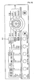
- FIGs. 3 and 4 illustrate a laundry machine according to a first preferred embodiment of the present invention.
- the laundry machine includes a machine body 100, a tub 200, a drum 300, a steam supply unit 400, a water inlet port 141, a water inlet pipe 500, and a primary steam supply pipe 610.
- the laundry machine is a drum type washing machine.
- the tub, in which washing water is received, is not necessarily provided for the drying machine.
- the machine body 100 constitutes the external appearance of the drum type washing machine. At the front part of the machine body 100 is formed a laundry inlet hole 110.
- the tub 200 is mounted in the machine body 100 in a supported state.
- a door 120 is mounted to the machine body 100 adjacent to the laundry inlet hole 110 for opening and closing the laundry inlet hole 110.
- a water drainage pipe 210 To the lower part of the tub 200 is connected a water drainage pipe 210, through which washing water (or cleansing water) is drained.
- a storage part 220 At the lower part of the tub 200, to which the water drainage pipe 210 is connected, is formed a storage part 220, which protrudes outward. In the storage part 220 is mounted a heater 230.
- a temperature sensor (not shown) is further located in the space where the heater 230 is located because the temperature of the washing water heated by the heater 230 can be accurately detected by the temperature sensor.
- the drum 300 is rotatably mounted in the tub 200, and is disposed such that the open side of the drum 300 is directed to the laundry inlet hole 110 of the machine body 100.
- a plurality of through-holes 310 are formed at the circumference of the drum 300, through which washing water and steam supplied into the tub 200 are introduced into the drum 300.
- a gasket 130 Between the laundry inlet hole 110 of the machine body 100 and the front end of the drum 300 is mounted a gasket 130, by which the space defined between the laundry inlet hole 110 of the machine body 100 and the front end of the drum 300 is partitioned from the inner space of the machine body 100.
- the steam supply unit 400 is mounted in the machine body 100 for generating a predetermined amount of steam.
- the steam supply unit 400 is constructed to evaporate water using high-temperature heat. As shown in FIG. 4 , the steam supply unit 400 includes a case 410 and a heater' 420.
- the case 410 is located approximately at the same eight as or lower than the middle part of the machine body 100 in the machine body 100.
- This structure is provided in consideration of the fact that the discharge pressure of upward-flowing high-temperature steam is greater than the discharge pressure of downward-flowing high-temperature steam. This is because steam is generally lighter than air.
- the case 410 in which the steam is substantially generated, is located at a predetermined position approximately below the middle part of the machine body 100 in the machine body 100 such that the steam generated in the case 410 can be discharged while the steam flows upward, whereby the discharge of the steam is more smoothly performed.
- the case 410 is located approximately at the same height as or lower than the bottom of the drum 300 in the machine body 100.
- This structure is provided in consideration of the fact that the distance between the opposite sides of the machine body 100 and the tub 200 is very small, and therefore, it is very difficult to mount the case to the corresponding area.
- the heater 420 is constructed to heat the water stored in the case 410 such that the water is evaporated into steam.
- the heater 420 is disposed in the case 410.
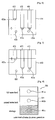
- the above-described steam supply unit 400 be further provided with a water level detection part 430 for detecting the water level of water stored in the case 410, and the machine body 100 be further provided with a water level display part 440 for informing a user of the information detected by the water level detection part 430.
- the water level detection part 430 is constructed using at least one of an electrode sensor for detecting the current water level using at least two electrodes, a temperature sensor for detecting the current water level based on the change of temperature difference, a weight sensor for detecting the current water level based on the change of weight difference, and a pressure sensor for detecting the current water level based on the change of pressure difference.
- the water level detection part 430 is constructed using the electrode sensor.
- the water level detection part 430 includes a common electrode 431 located at a predetermined position in the case 410, a low water level detecting electrode 432, and a high water level detecting electrode 433.
- the water level detection part 430 may include three or more electrodes.
- the low water level detecting electrode 432 has an exposed terminal 432a, which is located at the same height as the exposed terminal 431a of the common electrode 431.
- the high water level detecting electrode 433 has an exposed terminal 433a, which is located higher than the exposed terminal 431a of the common electrode 431 and the exposed terminal 432a of the low water level detecting electrode 432.
- the water level display part 440 is constructed using at least one of a plurality of LEDs, an LCD, and a speaker for outputting a warning sound to inform the current water level.
- the water level display part 440 includes a plurality of LEDs 441a, 441b, and 441c, and a display window 442, which is selectively activated by the flickering of the respective LEDs 441a, 441b, and 441c.
- the respective LEDs 441a, 441b, and 441c, and the display window 442 are disposed on a control panel of the machine body 100.
- the LED 441a serves to display the minimum water level
- the LED 441b serves to display the normal water level
- the LED 441c serves to display the maximum water level.
- the flickering of the respective LEDs 441a, 441b, and 441c is controlled by a control unit, which is not shown, based on the information detected by the water level detection part 430.
- the water inlet pipe 500 is a pipe constructed to supply water to the case 410 from the outside of the machine body 100.
- the water inlet pipe 500 communicates with the water inlet port 410.
- the water inlet port is exposed to the outside while the water inlet port communicates with the outer surface of the machine body 110, especially, the upper surface of the machine body 110, such that a user can easily supply water through the water inlet port.
- the water inlet port 410 not protrude outward above the upper surface of the machine body 100.
- cover part 140 for selectively covering the water inlet port 410.
- the cover part 140 be formed in the shape of a stopper to close the water inlet pipe 500.
- cover part 140 may be constructed such that the cover part 140 can be hingedly coupled to the machine body, or can slide along the corresponding area to selectively open or close the water inlet pipe 500.
- the primary steam supply pipe 610 is a pipe constructed to supply the steam generated in the steam supply unit 400 into the tub 200.
- one end of the primary steam supply pipe 610 is connected to the upper end or the upper surface of the case 410 of the steam supply unit 400, and the other end of the primary steam supply pipe 610 is connected to the tub 200 such that the other end of the primary steam supply pipe 610 extends through a predetermined position at the lower circumference of the tub 200, which is lower than the bottom of the drum 300, and communicates with the interior of the tub 200.
- the other end of the primary steam supply pipe 610 is located lower than the bottom of the drum 300 at the lower circumference of the tub 200 but is located higher than the heater 230 disposed in the storage part 220 of the tub.
- This structure provides an advantage in that the steam can uniformly flow to the whole area in the drum 300.
- the steam when the steam is supplied into the drum 300 from the bottom of the tub 200, the steam can be uniformly supplied to the upper space of the drum 300 as well as the bottom part of the drum 300.
- This structure solves the problem of the conventional art that the steam supplied from the top part of the drum cannot be uniformly supplied to the bottom of the drum.
- the steam is supplied from the bottom of the drum 300, and therefore, the steam supply route is further shortened. Consequently, the steam supply effect is increased.
- the steam supply unit 400 of the laundry machine according to the first preferred embodiment of the present invention as described above is constructed such that the user directly supplies water to the steam supply unit 400, the water may be oversupplied due to a mistake of the user, and, as a result, the water may overflow.
- the laundry machine according to the first preferred embodiment of the present invention includes the water level detection part 430 for detecting the water level in the case 410 and the water level display part 440 for displaying information of the water level detected by the water level detection part 430.
- the water level detection part 430 is out of order, a serious problem is caused.
- the laundry machine according to the first preferred embodiment of the present invention may further include an overflow pipe 411, which is connected to the case 410 for allowing the oversupplied water to naturally overflow therethrough.
- One end of the overflow pipe 411 is connected to the case 410 at the position of the case 410 corresponding to the oversupplied water level such that the overflow pipe 411 communicates with the case 410, and the other end of the overflow pipe 411 is connected to the bottom-side space of the tub 200 such that the overflow pipe 411 commmicates with the tub 200.
- the other end of the overflow pipe 411 may be connected to the drum 300 such that the overflow pipe 411 communicates with the interior of the drum 300.
- the laundry placed in the drum 300 may be wetted by the water overflowing through the overflow pipe 411.
- the laundry in the case that the laundry is to be washed according to the general washing process, it does not matter if the laundry is wetted by the oversupplied water.
- the laundry has already been washed and dried, it is necessary for the laundry not to be wetted by the oversupplied water.
- the other end of the overflow pipe 411 may be connected to the water drainage pipe 210 such that the overflow pipe 411 communicates with the water drainage pipe 210.
- the steam generated by the operation of the steam supply unit 400 may be directly discharged to the water drainage pipe 210 through the overflow pipe 411, which is not preferable.
- the water outlet side of the overflow pipe 411 to the tub 200 such that the overflow pipe 411 can communicate with the inside of the tub 200, especially, the bottom-side space of the tub 200.
- overflow pipe 411 may be formed using an additional pipe different from the primary steam supply pipe 610 as shown in the drawings of the first preferred embodiment of the present invention.
- the primary steam supply pipe 610 may be constructed such that the primary steam supply pipe 610 can also serve as the overflow pipe 411.
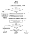
- a control method of supplying steam into the drum 300 in a washing process using the laundry machine with the above-stated construction according to the preferred embodiment of the present invention will be described in more detail with reference to FIG. 17 .
- operations using the steam in the respective washing processes include various operations, such as a laundry wetting operation, a soaking operation, a washing operation, a sterilizing operation, and a post-drying operation.
- the cover part 140 which is exposed to the outside, is manipulated through the upper surface of the machine body 100 such that the water inlet port 410 is opened, and then water is supplied through the water inlet pipe 500.
- the water supplied to the water inlet port 410 flows along the water inlet pipe 500, and is then supplied into the case 410, which is connected to the other end of the water inlet pipe 500.
- the water level detection part 430 disposed in the case 410 continuously detects the water level of water supplied into the case 410 to check the water level (S110).
- the detection of the water level by the water level detection part 430 is performed by checking whether electrical conduction between the common electrode 431 and the low water level detecting electrode 432 has been accomplished and electrical conduction between the common electrode 431 and the high water level detecting electrode 433 has been accomplished.
- the information of whether the electrical conduction has been accomplished is transmitted to the control unit (not shown), which controls the flickering of the respective LEDs of the water level display part 440 based on the information of whether the electrical conduction has been accomplished such that a user can recognize the current water level.
- a corresponding signal is transmitted to the control unit, which determines that the current water level in the case 410 is the minimum water level (a level higher than the heater) based on the information of whether the electrical conduction has been accomplished, and lights the specific LED 441c, which indicates the minimum water level, of the respective LEDs 441a, 441b, and 441c, as shown in FIG. 8 , whereby the user can recognize the current water level.
- a corresponding signal is transmitted to the control unit, which determines that the current water level in the case 410 is the maximum water level (full water level) based on the information of whether the electrical conduction has been accomplished, and lights the specific LED 441a, which indicates the maximum water level, of the respective LEDs 441a, 441b, and 441c, as shown in FIG. 9 , whereby the user can recognize the current water level.
- the water oversupplied in the course of supplying water into the case 410 is discharged into the tub 200 through the overflow pipe 411 connected to the case 410 such that the overflow pipe 411 communicates with the case 410. Consequently, no problem is caused due to the oversupplied water.
- the cover part 140 is closed, and the corresponding operation is carried out.
- control unit determines whether the checked water level for steam generation is higher or lower than the predetermined water level, and performs a control operation for steam generation or request of water supply based on the result of the determination.
- the control unit requests the user to supply water for steam generation such that the water for steam generation is manually supplied into the water storage case 410 of the steam supply unit 400 (S 120).
- requesting the user to supply water for steam generation is preferably accomplished by providing information, through the display screen on the control panel, of the fact that the water for steam generation is insufficient and displaying a message requesting to supply water for steam generation.
- the respective LEDs 441a, 441b, and 441c of the water level display part 440 are repeatedly flickered such that the user can recognize the shortage of the water for steam generation.
- the user manipulates the cover part 140, which is exposed to the outside, through the upper surface of the machine body 100 to open the water inlet pipe 500, and supplies water for steam generation to the water inlet pipe 500.
- the water for steam generation which has been supplied to the water inlet pipe 500, flows along the water inlet pipe 500, and is then supplied into the water storage case 410, which is connected to the other end of the water inlet pipe 500.
- the control unit continuously checks the water level of the water for steam generation supplied into the water storage case 410 based on the information of the electrical conduction checked by the water level detection part 430, and, when the water level of the water for steam generation reaches the predetermined water level, the control unit informs the user that the water supply must be interrupted.
- informing the user that the water supply must be interrupted is identical to requesting to further supply water. Specifically, informing the user that the water supply must be interrupted is accomplished by providing information, through the display screen on the control panel, of the fact that the water level of the water for steam generation has reached the maximum water level and displaying a message requesting to interrupt the supply of water for steam generation.
- the control unit controls the heater 420 to generate steam (S140).
- the water for steam generation stored in the water storage case 410 is evaporated by high-temperature heat emitted from the heater 420. As a result, steam is generated in the water storage case 410.
- the steam generated as described above is supplied into the outer tub 200 through the primary steam supply pipe 610, which communicates with the water storage case 410 (S150).
- the primary steam supply pipe 610 is connected to the outer tub 200 such that the primary steam supply pipe 610 communicates with the bottom space of the outer tub 200. Consequently, the steam is supplied from the water storage case 410 to the bottom space of the outer tub 200 through the primary steam supply pipe 610.
- the steam flows upward from the bottom space of the outer tub 200, and is then supplied into the drum 300.
- the water level of the water for steam generation in the water storage case 410 is continuously checked by the control unit.
- control unit continuously checks the water level of the water for steam generation through the water level detection part 430 in the course of controlling the steam to be generated.
- the water level of the water for steam generation continuously checked through the above-described process be displayed through the water level display part 440, whereby the user can recognize the current water level in real time.
- the control unit interrupts the heat emission from the heater 420, and, at the same time, requests the user to further supply water for steam generation.
- requesting the user to supply the water for steam generation is possible by providing information, through the display screen on the control panel, of the fact that the water for steam generation is insufficient and displaying a message requesting to supply water for steam generation, as described above.
- control unit controls the above-described process to be continuously repeatedly carried out through the determination of the water level of the water for steam generation supplied.
- the washing efficiency of the laundry in the drum is further improved by virtue of the steam supplied as described above, and the laundry placed at the bottom side in the drum 300 is smoothly washed by the steam flowing forward from the bottom side of the drum 300.
- the laundry placed at the bottom side in the drum 300 is washed or sterilized, for example, in a steaming fashion.
- control unit interrupts the rotation of the drum 300, the driving of a circulating pump 720, and the heat emission of the heater 420, and terminates the corresponding operation.
- the above-described first preferred embodiment of the present invention is constructed such that the steam is supplied only into the bottom space of the drum 300 through the bottom of the tub 200.
- the amount of the steam actually supplied to the upper space of the drum 300 is remarkably small due to the laundry placed in the bottom space of the drum 300.
- the steam cannot be uniformly supplied to the upper and lower parts of the laundry, and therefore, the washing efficiency is lowered.
- the laundry machine according to the first preferred embodiment of the present invention may further comprise an additional auxiliary steam supply part 620, as shown in FIG. 10 , in addition to the above-described structure of the laundry machine according to the first preferred embodiment of the present invention.
- the auxiliary steam supply part may be an auxiliary steam supply pipe.
- the primary steam supply pipe 610 which supplies the steam generated in the steam supply unit 400 into the tub 200, is connected to the tub in such a manner that the steam can be supplied into the drum 300 through the bottom space of the tub 200.
- the auxiliary steam supply pipe 620 is constructed such that the steam generated in the steam supply unit 400 can be injected toward the bottom-side space of the drum 300 from the top-side space of the drum 300.
- an injection nozzle for injecting steam.
- the discharge end of the auxiliary steam supply pipe 620 extends through the gasket 130 such that the auxiliary steam supply pipe communicates with the interior of the drum 300.
- auxiliary steam supply pipe 620 diverge from a predetermined region of the pipe line of the primary steam supply pipe 610. This construction minimizes the pipe line extending from the steam supply unit 400, and therefore, the line distribution is simplified.
- a flow direction control valve 630 for allowing selective supply and/or interruption of the steam to the respective steam supply pipes be further provided at the region where the auxiliary steam supply pipe 620 diverges from the primary steam supply pipe 610.
- the steam may be supplied from the bottom part of the drum 300, the steam may be supplied from the top part of the drum 300, or the steam may be supplied simultaneously from the top and bottom parts of the drum 300 according to the corresponding operation.
- the flow direction control valve may adjust the opening degree of the pipe lines to control the amount of the steam supplied.
- FIG. 11 illustrates a modified example of the laundry machine according to the first preferred embodiment of the present invention.
- the steam supply unit 400 is located approximately at the same height as or lower than the bottom part of the drum in the machine body 100. Furthermore, the water inlet pipe 500 communicates with the upper front part of the machine body 100, and therefore, the water inlet pipe 500 is exposed to the outside.
- the water inlet side of the water inlet pipe 500 is not restricted to a specific region but may be located at any one of all the sides of the machine body 100.
- the water inlet side of the water inlet pipe 500 may be divided into a plurality of water inlet branches such that the water inlet pipe 500 can communicate simultaneously with one or more sides of the machine body 100.
- FIGs. 12 and 13 illustrate a modified example of the laundry machine according to the first preferred embodiment of the present invention, which further comprises a construction for washing water circulation.
- the laundry machine according to the present invention shown in FIGs. 12 and 13 further comprises a washing water circulation unit 700 mounted in the machine body 100 for circulating the washing water in the tub 200 such that the washing water can be injected into the drum 300 in addition to the above-described structure of the laundry machine according to the first preferred embodiment of the present invention.
- a washing water circulation unit 700 mounted in the machine body 100 for circulating the washing water in the tub 200 such that the washing water can be injected into the drum 300 in addition to the above-described structure of the laundry machine according to the first preferred embodiment of the present invention.
- the washing water circulation unit 700 is a structure for injecting the washing water into the drum 300 when the laundry is wetted and/or when the washing operation is carried out, whereby the wetting process of the laundry is more smoothly carried out, and therefore, the washing efficiency is improved.
- the washing water circulation unit 700 includes an inlet pipe 710 for receiving the washing water from the tub 200, a circulating pump 720 mounted on the pipe line of the inlet pipe 710 for pumping the washing water, a guide pipe 730 for guiding the washing water pumped by the circulating pump 720 to the upper space of the machine body 100, and an injection nozzle 740 coupled to the discharge side of the guide pipe 730 and extending through the gasket 130, such that the injection nozzle 740 can communicate with the inside upper end of the drum 300, for injecting the pumped washing water.
- the inlet pipe 701 is connected to the water drainage pipe 210 such that the inlet pipe 701 can communicate with the water drainage pipe 210.
- an on-off valve 750 is mounted on the pipe line of the inlet pipe 710 or the pipe line of the water drainage pipe 210 for selectively opening and closing the two pipe lines.
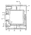
- FIGs. 14 and 15 illustrate a steam supply unit detachably attached to the machine body of the laundry machine according to the first preferred embodiment of the present invention.
- the steam supply unit 900 includes a case 910 and a heater 920.
- the case 910 is detachably attached to the machine body 100, which will be described below in detail.
- the case 910 of the laundry machine shown in FIGs. 14 and 15 is received in the machine body 100 through one side of the machine body 100.
- the case 910 is received in the machine body 100 in a drawer-type inserting fashion through the lower front part (preferably, the lower front corner) of the machine body 100 such that the user can easily and conveniently manipulate the case 910.
- a guide part 150 is mounted in the machine body 100 for guiding the location position of the case 910 while supporting the opposite sides of the bottom of the case 910 when the case 910 is inserted into the machine body.
- the guide part 150 is formed in the shape of a box having a predetermined receiving space defined therein.
- the heater 920 is constructed to heat the water stored in the case 910 into steam.
- the heater 920 may be located in the bottom space of the guide part 150, which is the lower part of the case 910.
- the bottom of the case 910 be made of a metal material having high thermal conductivity.
- the heater 920 may be integrally fixed in the case 910.
- one end of the primary steam supply pipe 610 which guides the discharge of the steam, is connected to the guide part 150 such that the primary steam supply pipe 610 communicates with the interior space of the guide part 150, and the other end of the primary steam supply pipe 610 is connected to the tub 200 such that the primary steam supply pipe 610 communicates with the interior space of the tub 200.
- the other end of the primary steam supply pipe 610 is connected to the tub 200 through the lower circumferential part of the tub 200 such that the steam supply pipe 610 communicates with the interior of the tub 200.
- the laundry machine shown in FIGs. 14 and 15 may further comprise an auxiliary steam supply pipe 620 for injecting the steam into the drum 300 through the upper space of the tub 200.
- auxiliary steam supply pipe 620 diverge from a predetermined region of the pipe line of the primary steam supply pipe 610. It is also preferable that a flow direction control valve 630 for allowing selective supply and/or interruption of the steam to the respective steam supply pipes be further provided at the region where the auxiliary steam supply pipe diverges from the primary steam supply pipe.
- the discharge end of the auxiliary steam supply pipe 620 extends through the gasket 130 such that the auxiliary steam supply pipe communicates with the interior of the drum 300.
- the laundry machine shown in FIGs. 14 and 15 further comprises a washing water circulation unit 700 mounted in the machine body 100 for circulating the washing water in the tub 200 such that the washing water can be injected into the drum 300.
- a washing water circulation unit 700 mounted in the machine body 100 for circulating the washing water in the tub 200 such that the washing water can be injected into the drum 300.
- the washing water circulation unit 700 includes an inlet pipe 710 for receiving the washing water from the tub 200, a circulating pump 720 mounted on the pipe line of the inlet pipe 710 for pumping the washing water, a guide pipe 730 for guiding the washing water pumped by the circulating pump 720 to the upper space of the machine body 100, and an injection nozzle 740 coupled to the discharge side of the guide pipe 730 and extending through the gasket 130, such that the injection nozzle 740 can communicate with the inside upper end of the drum 300, for injecting the pumped washing water.
- laundry machine according to the present invention can be modified in various manners.
- FIG. 16 which are identical to those of the previously described first preferred embodiment, indicate the same structural components as the first preferred embodiment, and the structural components having the same reference numbers as the first preferred embodiment perform the same functions as the first
- the case 410 and the heater 420 are located at the upper part of the machine body. More specifically, the case and the heater are located above the tub.
- the user can open the cover part 140, and then directly supply the water to the case through the water inlet port 141.
- the second preferred embodiment of the present invention is characterized in that the steam supply unit is disposed at the upper part of the machine body, which is unlike the previously described first preferred embodiment.
- Other constructions and features of the first preferred embodiment may be applied to the second preferred embodiment of the present invention.
Landscapes
- Engineering & Computer Science (AREA)
- Textile Engineering (AREA)
- Detail Structures Of Washing Machines And Dryers (AREA)
- Control Of Washing Machine And Dryer (AREA)
- Centrifugal Separators (AREA)
Claims (27)
- Lave-linge comprenant :un corps de lave-linge (100) ;un tambour (300) monté dans le corps de lave-linge pour recevoir le linge;une unité d'alimentation en vapeur (400) montée dans le corps de lave-linge (100) pour produire de la vapeur, etune partie d'alimentation en vapeur primaire (610) pour introduire la vapeur dans le tambour (300) ;caractérisé en ce que l'unité d'alimentation en vapeur (400) est conçue de manière à recevoir de l'eau introduite manuellement par un utilisateur à travers un orifice d'admission d'eau (141) exposé à l'extérieur du corps de lave-linge.
- Lave-linge selon la revendication 1, comprenant en outre :une cuve (200) pour contenir de l'eau de lavage, dans lequel la cuve (200) est montée de manière rotative à l'intérieur du corps de lave-linge (100).
- Lave-linge selon la revendication 2, dans lequel la partie d'alimentation en vapeur primaire (610) comprend un tuyau d'alimentation en vapeur primaire (610) adapté pour communiquer avec l'intérieur de la cuve (200) par une partie périphérique inférieure de la cuve (200).
- Lave-linge selon la revendication 3, dans lequel la cuve (200) est munie dans sa partie inférieure d'une partie de stockage (220), qui fait saillie vers le bas, la partie de stockage (220) comportant un dispositif de chauffage (230) adapté pour chauffer l'eau de lavage présente dans celle-ci.
- Lave-linge selon la revendication 4, dans lequel une position de la cuve (200) à travers laquelle s'étend le tuyau d'alimentation en vapeur primaire (610) est inférieure à une partie inférieure du tambour (300) et supérieure à une position au niveau de laquelle est monté le dispositif de chauffage (230).
- Lave-linge selon la revendication 1, dans lequel l'unité d'alimentation en vapeur (400) comprend :un boîtier (410) conçu pour recevoir de l'eau à travers l'orifice d'admission d'eau (141) ; etun dispositif de chauffage (420) pour chauffer l'eau afin de produire de la vapeur.
- Lave-linge selon la revendication 6, dans lequel le boîtier (410) est disposé à l'intérieur et au niveau d'une extrémité supérieure du corps de lave-linge (100).
- Lave-linge selon la revendication 7, dans lequel le boîtier (400) est logé dans le corps de lave-linge (100) en étant inséré à la manière d'un tiroir à travers la partie avant du corps de lave-linge (100).
- Lave-linge selon la revendication 6, dans lequel le boîtier (400) est disposé dans la partie supérieure du tambour (300).
- Lave-linge selon la revendication 6, dans lequel le boîtier est situé à peu près au niveau d'une position inférieure à une partie centrale du corps de lave-linge (100).
- Lave-linge selon la revendication 10, dans lequel le boîtier (400) est situé sensiblement en une position inférieure à la partie inférieure du tambour (300).
- Lave-linge selon l'une quelconque des revendications 9 à 11, comprenant en outre :un tuyau d'arrivée d'eau (500), ayant une extrémité qui communique avec l'orifice d'admission d'eau (141) et l'autre extrémité qui communique avec le boîtier (410), afin d'introduire de l'eau dans le boîtier (410) depuis l'orifice d'admission d'eau (141).
- Lave-linge selon la revendication 6, comprenant en outre :une partie couvercle (140) pour permettre une communication sélective entre l'orifice d'admission d'eau (141) et l'extérieur.
- Lave-linge selon la revendication 6, dans lequel le boîtier (410) est muni d'un tuyau de trop-plein (411) pour permettre à l'eau introduite en excès de s'en aller par celui-ci.
- Lave-linge selon la revendication 12, dans lequel une extrémité du tuyau de trop-plein (411) communique avec le boîtier (410) au niveau de la position du boîtier qui correspond à un niveau d'eau introduite en excès, et l'autre extrémité du tuyau de trop-plein (411) communique avec au moins un élément parmi le tambour (300), la cuve (200), et un tuyau d'évacuation d'eau (210) pour évacuer l'eau de la cuve (200).
- Lave-linge selon la revendication 6, comprenant en outre :une partie de détection de niveau d'eau (430) pour détecter un niveau d'eau de l'eau introduite dans le boîtier (410).
- Lave-linge selon la revendication 16, dans lequel le dispositif de chauffage (420) est commandé en fonction du niveau d'eau détecté par la partie de détection de niveau d'eau (430).
- Lave-linge selon la revendication 16, dans lequel la partie de détection de niveau d'eau (430) comprend un capteur à électrode ayant au moins deux électrodes.
- Lave-linge selon la revendication 16, comprenant en outre :un dispositif d'affichage (440) pour afficher un niveau d'eau afin d'informer un utilisateur de l'information détectée par la partie de détection de niveau d'eau (430).
- Lave-linge selon la revendication 1, comprenant en outre :une partie d'alimentation en vapeur auxiliaire (620) pour introduire la vapeur dans le tambour par un côté supérieur du tambour (300).
- Lave-linge selon la revendication 20, dans lequel la partie d'alimentation en vapeur auxiliaire est un tuyau d'alimentation en vapeur auxiliaire (620) qui d'embranche sur la partie d'alimentation en vapeur primaire.
- Lave-linge selon la revendication 21, comprenant en outre :une soupape de commande de direction d'écoulement (630) montée au niveau d'une région où le tuyau d'alimentation en vapeur auxiliaire (620) s'embranche sur le tuyau d'alimentation en vapeur primaire (610) pour ouvrir et fermer sélectivement les conduites respectives ou afin de commander le degré d'ouverture des conduites respectives.
- Lave-linge selon la revendication 2, comprenant en outre :une unité de circulation d'eau de lavage (700) pour faire circuler l'eau de lavage introduite dans la cuve (200) de telle sorte que l'eau de lavage peut être introduite dans le tambour (300).
- Lave-linge selon la revendication 23, dans lequel l'unité de circulation d'eau de lavage (700) comprend :un tuyau d'admission (701) pour recevoir l'eau de lavage de la cuve (200) ;une pompe de circulation (720) montée sur une conduite du tuyau d'admission (701) afin de pomper l'eau de lavage ; etun tuyau de guidage (730) pour amener l'eau de lavage pompée par la pompe de circulation (720) dans le tambour (300).
- Lave-linge selon la revendication 21 ou 24, dans lequel la partie d'alimentation en vapeur auxiliaire comprend un tuyau d'alimentation en vapeur auxiliaire (620), le lave-linge comprenant en outre :des buses d'injection (740) disposées à l'extrémité de la partie d'alimentation en vapeur auxiliaire (620) et à l'extrémité du tuyau de guidage (730) pour injecter de la vapeur et de l'eau de lavage, respectivement, les buses d'injection (740) s'étendant à travers un joint d'étanchéité (130) de telle sorte que les buses d'injection (740) peuvent communiquer avec le côté supérieur du tambour (300).
- Lave-linge selon la revendication 19, dans lequel le dispositif d'affichage comprend au moins un élément parmi une pluralité de diodes lumineuses, un affichage à cristaux liquides, et un haut-parleur pour émettre un signal sonore d'avertissement afin d'informer du niveau d'eau en cours.
- Procédé pour faire fonctionner un lave-linge comprenant un corps de lave-linge (100), un tambour (300) monté dans le corps de lave-linge (100) afin de recevoir le linge et une unité d'alimentation en vapeur (400) montée dans le corps de lave-linge (100) pour produire de la vapeur, comprenant les étapes consistant à :introduire de la vapeur dans le tambour (300) par une partie d'alimentation en vapeur primaire (610) ;caractérisé par les étapes consistant à :recevoir de l'eau fournie manuellement par un utilisateur à travers un orifice d'admission d'eau (141) exposé à l'extérieur du corps de lave-linge (100) ; etproduire de la vapeur en utilisant l'eau introduite manuellement par l'orifice d'admission d'eau dans l'unité d'alimentation en vapeur (400).
Applications Claiming Priority (4)
| Application Number | Priority Date | Filing Date | Title |
|---|---|---|---|
| KR1020050046037A KR100848908B1 (ko) | 2005-05-31 | 2005-05-31 | 세탁 장치 |
| KR1020050046038A KR100845845B1 (ko) | 2005-05-31 | 2005-05-31 | 세탁 장치 |
| KR1020050046040A KR100904427B1 (ko) | 2005-05-31 | 2005-05-31 | 세탁 장치 및 그의 제어 방법 |
| PCT/KR2006/001430 WO2006129916A1 (fr) | 2005-05-31 | 2006-04-18 | Machine a laver le linge |
Publications (2)
| Publication Number | Publication Date |
|---|---|
| EP1899522A1 EP1899522A1 (fr) | 2008-03-19 |
| EP1899522B1 true EP1899522B1 (fr) | 2009-08-12 |
Family
ID=37481814
Family Applications (1)
| Application Number | Title | Priority Date | Filing Date |
|---|---|---|---|
| EP06757485A Revoked EP1899522B1 (fr) | 2005-05-31 | 2006-04-18 | Machine a laver le linge |
Country Status (6)
| Country | Link |
|---|---|
| US (1) | US8438755B2 (fr) |
| EP (1) | EP1899522B1 (fr) |
| AT (1) | ATE439465T1 (fr) |
| AU (1) | AU2006253222B2 (fr) |
| DE (1) | DE602006008467D1 (fr) |
| WO (1) | WO2006129916A1 (fr) |
Cited By (1)
| Publication number | Priority date | Publication date | Assignee | Title |
|---|---|---|---|---|
| EP2818593A1 (fr) | 2013-06-25 | 2014-12-31 | Electrolux Appliances Aktiebolag | Appareil ménager pour le traitement du linge comportant un réservoir d'eau |
Families Citing this family (29)
| Publication number | Priority date | Publication date | Assignee | Title |
|---|---|---|---|---|
| EP2034082B1 (fr) | 2005-03-16 | 2012-08-22 | LG Electronics Inc. | Machine à laver à la vapeur et son procédé de commande |
| EP2312048B1 (fr) | 2006-06-01 | 2012-08-22 | Electrolux Home Products Corporation N.V. | Appareil ménager avec un réservoir d'eau |
| US7627920B2 (en) | 2006-06-09 | 2009-12-08 | Whirlpool Corporation | Method of operating a washing machine using steam |
| US7730568B2 (en) | 2006-06-09 | 2010-06-08 | Whirlpool Corporation | Removal of scale and sludge in a steam generator of a fabric treatment appliance |
| US7941885B2 (en) | 2006-06-09 | 2011-05-17 | Whirlpool Corporation | Steam washing machine operation method having dry spin pre-wash |
| US7765628B2 (en) | 2006-06-09 | 2010-08-03 | Whirlpool Corporation | Steam washing machine operation method having a dual speed spin pre-wash |
| US7841219B2 (en) | 2006-08-15 | 2010-11-30 | Whirlpool Corporation | Fabric treating appliance utilizing steam |
| US7591859B2 (en) | 2006-08-15 | 2009-09-22 | Whirlpool Corporation | Water supply control for a steam generator of a fabric treatment appliance using a weight sensor |
| US7707859B2 (en) | 2006-08-15 | 2010-05-04 | Whirlpool Corporation | Water supply control for a steam generator of a fabric treatment appliance |
| US7886392B2 (en) | 2006-08-15 | 2011-02-15 | Whirlpool Corporation | Method of sanitizing a fabric load with steam in a fabric treatment appliance |
| US7665332B2 (en) | 2006-08-15 | 2010-02-23 | Whirlpool Corporation | Steam fabric treatment appliance with exhaust |
| US7681418B2 (en) | 2006-08-15 | 2010-03-23 | Whirlpool Corporation | Water supply control for a steam generator of a fabric treatment appliance using a temperature sensor |
| US7753009B2 (en) | 2006-10-19 | 2010-07-13 | Whirlpool Corporation | Washer with bio prevention cycle |
| KR101342367B1 (ko) * | 2006-12-19 | 2013-12-16 | 엘지전자 주식회사 | 스팀건조기 |
| US8393183B2 (en) | 2007-05-07 | 2013-03-12 | Whirlpool Corporation | Fabric treatment appliance control panel and associated steam operations |
| DE102008026114B4 (de) * | 2007-06-08 | 2020-08-06 | Lg Electronics Inc. | Steuerungsverfahren für einen Dampfgenerator sowie Bekleidungsbehandlungsmaschine mit diesem |
| US7966683B2 (en) | 2007-08-31 | 2011-06-28 | Whirlpool Corporation | Method for operating a steam generator in a fabric treatment appliance |
| US8037565B2 (en) | 2007-08-31 | 2011-10-18 | Whirlpool Corporation | Method for detecting abnormality in a fabric treatment appliance having a steam generator |
| US7905119B2 (en) | 2007-08-31 | 2011-03-15 | Whirlpool Corporation | Fabric treatment appliance with steam generator having a variable thermal output |
| US8555675B2 (en) | 2007-08-31 | 2013-10-15 | Whirlpool Corporation | Fabric treatment appliance with steam backflow device |
| US7690062B2 (en) | 2007-08-31 | 2010-04-06 | Whirlpool Corporation | Method for cleaning a steam generator |
| US8555676B2 (en) | 2007-08-31 | 2013-10-15 | Whirlpool Corporation | Fabric treatment appliance with steam backflow device |
| US7861343B2 (en) | 2007-08-31 | 2011-01-04 | Whirlpool Corporation | Method for operating a steam generator in a fabric treatment appliance |
| US7918109B2 (en) | 2007-08-31 | 2011-04-05 | Whirlpool Corporation | Fabric Treatment appliance with steam generator having a variable thermal output |
| KR20090030901A (ko) | 2007-09-21 | 2009-03-25 | 엘지전자 주식회사 | 세탁장치 |
| EP2610397B1 (fr) * | 2011-12-28 | 2020-04-01 | Electrolux Home Products Corporation N.V. | Appareil domestique pour sécher le linge doté d'un réservoir pour liquides avec une entrée de remplissage |
| CN106702676B (zh) * | 2015-07-27 | 2020-11-10 | 青岛海尔滚筒洗衣机有限公司 | 一种用于洗衣机的蒸汽发生装置及洗衣机 |
| US20230002955A1 (en) * | 2021-07-01 | 2023-01-05 | Haier Us Appliance Solutions, Inc. | Fluid delivery system for a dryer appliance |
| WO2023029193A1 (fr) * | 2021-08-30 | 2023-03-09 | 无锡小天鹅电器有限公司 | Dispositif de traitement de linge |
Family Cites Families (38)
| Publication number | Priority date | Publication date | Assignee | Title |
|---|---|---|---|---|
| DE604415C (fr) | ||||
| DE577336C (de) | 1931-09-04 | 1933-05-30 | Inventia Patent Verwert Ges | Beheizbare Eingefaess-Trommelwaschmaschine |
| US2562843A (en) * | 1946-11-21 | 1951-07-31 | Bohus Mek Verkst S Aktiebolag | Electrical heating apparatus and method |
| DE1017129B (de) | 1956-02-03 | 1957-10-10 | Erich Sulzmann | Verfahren zum Waschen und Spuelen in Stroemungswaschmaschinen |
| GB2021953B (en) * | 1978-03-14 | 1982-11-03 | Health Lab Service Board | Autoclave steam injection |
| US4207683A (en) * | 1979-02-01 | 1980-06-17 | Horton Roberta J | Clothes dryer |
| US4612090A (en) * | 1981-06-03 | 1986-09-16 | Ellis Jr John C | Water degasification and distillation apparatus |
| IT8211695U1 (it) * | 1982-06-10 | 1983-12-10 | Biancalani Mauro | Ferro da stiro a vapore con vaschetta per l'acqua disposta posteriormente |
| IT1181072B (it) | 1984-02-13 | 1987-09-23 | Zanussi A Spa Industrie | Vasca in materia plastica per macchine lavabiancheria |
| JPS61128995A (ja) | 1984-11-26 | 1986-06-17 | 三洋電機株式会社 | 洗濯機 |
| JPH0673591B2 (ja) * | 1989-03-13 | 1994-09-21 | 東静電気株式会社 | 布団類の再生方法およびその装置 |
| KR930004677Y1 (ko) * | 1991-06-11 | 1993-07-22 | 삼성전자 주식회사 | 삶아 세탁하는 세탁기의 응축수단을 갖는 수조뚜껑 |
| JPH06233898A (ja) | 1992-12-15 | 1994-08-23 | Toshiba Corp | 衣類乾燥機 |
| JP3157401B2 (ja) | 1994-09-09 | 2001-04-16 | 株式会社東芝 | 冷蔵庫 |
| KR0172877B1 (ko) | 1995-12-11 | 1999-05-01 | 구자홍 | 건조겸용 드럼세탁기 |
| FR2745896B1 (fr) * | 1996-03-07 | 1998-04-24 | Armines | Procede et installation de sechage d'une masse de matiere fibreuse humide, notamment d'une masse de linge |
| KR970070295A (ko) | 1996-04-16 | 1997-11-07 | 이정식 | 증기를 이용한 세탁기 |
| US6938886B2 (en) * | 2000-05-16 | 2005-09-06 | Appliance Development Corporation | Apparatus for conditioning air |
| DE10028944B4 (de) | 2000-06-16 | 2016-01-28 | Herbert Kannegiesser Gmbh | Verfahren und Vorrichtung zur Nassbehandlung von Wäsche |
| CH695383A5 (de) | 2001-07-10 | 2006-04-28 | V Zug Ag | Wäschetrockner oder Waschautomat mit Bedampfungsvorrichtung. |
| KR20030012145A (ko) | 2001-07-30 | 2003-02-12 | 주식회사 엘지이아이 | 드럼 세탁기의 수량 제어방법 |
| KR100929229B1 (ko) * | 2002-11-28 | 2009-12-01 | 엘지전자 주식회사 | 드럼 세탁기 도어 열림 제어방법 |
| DE10260151A1 (de) | 2002-12-20 | 2004-07-01 | BSH Bosch und Siemens Hausgeräte GmbH | Wäschetrockner und Verfahren zur Geruchsentfernung aus Textilien |
| EP1441059B1 (fr) | 2003-01-25 | 2012-01-18 | Electrolux Home Products Corporation N.V. | Procédé de traitement de textiles dans un sèche-linge domestique |
| DE10302866B4 (de) | 2003-01-25 | 2010-08-12 | Electrolux Home Products Corporation N.V. | Wäschetrockner mit einer Einrichtung zum Einsprühen von Zusätzen und Verfahren hierfür |
| KR100517613B1 (ko) | 2003-03-31 | 2005-09-28 | 엘지전자 주식회사 | 증기분사식 드럼세탁기 |
| KR100510680B1 (ko) * | 2003-03-31 | 2005-08-31 | 엘지전자 주식회사 | 증기분사식 드럼세탁기 |
| KR100504501B1 (ko) | 2003-04-14 | 2005-08-02 | 엘지전자 주식회사 | 증기분사식 드럼세탁기의 세탁방법 |
| KR20050015758A (ko) | 2003-08-07 | 2005-02-21 | 삼성전자주식회사 | 드럼 세탁기 및 그 제어방법 |
| KR100540749B1 (ko) | 2003-08-13 | 2006-01-10 | 엘지전자 주식회사 | 드럼세탁기용 증기발생장치 |
| KR20050017490A (ko) * | 2003-08-13 | 2005-02-22 | 엘지전자 주식회사 | 드럼 세탁기용 증기 세탁 방법 |
| KR100500887B1 (ko) | 2003-08-13 | 2005-07-14 | 엘지전자 주식회사 | 드럼 세탁기의 증기발생장치 및 그 방법 |
| KR20050065721A (ko) | 2003-12-23 | 2005-06-30 | 삼성전자주식회사 | 세탁기 및 그 제어방법 |
| KR20050093260A (ko) | 2004-03-18 | 2005-09-23 | 주식회사 대우일렉트로닉스 | 드럼 세탁기의 세탁 방법 |
| KR20060023017A (ko) | 2004-09-08 | 2006-03-13 | 엘지전자 주식회사 | 세탁기 |
| KR100531330B1 (ko) | 2005-04-15 | 2005-11-29 | 엘지전자 주식회사 | 듀얼분사식 드럼세탁기의 세탁방법 |
| KR100531332B1 (ko) | 2005-04-21 | 2005-11-29 | 엘지전자 주식회사 | 드럼세탁기의 세탁물 구김 제거방법 |
| KR20050044884A (ko) | 2005-04-27 | 2005-05-13 | 엘지전자 주식회사 | 증기분사식 드럼세탁기 |
-
2006
- 2006-04-18 AT AT06757485T patent/ATE439465T1/de not_active IP Right Cessation
- 2006-04-18 DE DE602006008467T patent/DE602006008467D1/de not_active Expired - Lifetime
- 2006-04-18 US US11/629,662 patent/US8438755B2/en active Active
- 2006-04-18 WO PCT/KR2006/001430 patent/WO2006129916A1/fr not_active Ceased
- 2006-04-18 EP EP06757485A patent/EP1899522B1/fr not_active Revoked
- 2006-04-18 AU AU2006253222A patent/AU2006253222B2/en not_active Ceased
Cited By (1)
| Publication number | Priority date | Publication date | Assignee | Title |
|---|---|---|---|---|
| EP2818593A1 (fr) | 2013-06-25 | 2014-12-31 | Electrolux Appliances Aktiebolag | Appareil ménager pour le traitement du linge comportant un réservoir d'eau |
Also Published As
| Publication number | Publication date |
|---|---|
| WO2006129916A1 (fr) | 2006-12-07 |
| DE602006008467D1 (de) | 2009-09-24 |
| ATE439465T1 (de) | 2009-08-15 |
| EP1899522A1 (fr) | 2008-03-19 |
| AU2006253222B2 (en) | 2009-08-20 |
| AU2006253222A1 (en) | 2006-12-07 |
| US8438755B2 (en) | 2013-05-14 |
| US20080201866A1 (en) | 2008-08-28 |
Similar Documents
| Publication | Publication Date | Title |
|---|---|---|
| EP1899522B1 (fr) | Machine a laver le linge | |
| US8443635B2 (en) | Laundry machine | |
| US8387189B2 (en) | Method for washing of washer | |
| JP4985806B2 (ja) | 洗濯機 | |
| US20090293557A1 (en) | Steam Generator and Washing Machine Having the Same | |
| EP1873298B1 (fr) | Générateur de vapeur et machine de blanchisserie en étant dotée | |
| CN1989289A (zh) | 产生和利用蒸汽的洗衣机 | |
| CN1989287B (zh) | 洗衣机 | |
| CN1969077B (zh) | 洗衣机的洗涤方法 | |
| KR100698304B1 (ko) | 드럼 세탁기의 세척조 세정 방법 | |
| CN101094950B (zh) | 滚筒洗衣机的控制方法 | |
| KR101521916B1 (ko) | 의류 처리 장치 및 그 제어 방법 | |
| KR100904427B1 (ko) | 세탁 장치 및 그의 제어 방법 | |
| KR100845845B1 (ko) | 세탁 장치 | |
| KR100803126B1 (ko) | 세탁 장치 및 그의 제어 방법 | |
| KR101050094B1 (ko) | 드럼세탁기의 건조덕트 고정구조물 | |
| JP2021186055A (ja) | 洗濯乾燥機および洗濯機 |
Legal Events
| Date | Code | Title | Description |
|---|---|---|---|
| PUAI | Public reference made under article 153(3) epc to a published international application that has entered the european phase |
Free format text: ORIGINAL CODE: 0009012 |
|
| 17P | Request for examination filed |
Effective date: 20070115 |
|
| AK | Designated contracting states |
Kind code of ref document: A1 Designated state(s): AT BE BG CH CY CZ DE DK EE ES FI FR GB GR HU IE IS IT LI LT LU LV MC NL PL PT RO SE SI SK TR |
|
| 17Q | First examination report despatched |
Effective date: 20080514 |
|
| DAX | Request for extension of the european patent (deleted) | ||
| GRAP | Despatch of communication of intention to grant a patent |
Free format text: ORIGINAL CODE: EPIDOSNIGR1 |
|
| GRAS | Grant fee paid |
Free format text: ORIGINAL CODE: EPIDOSNIGR3 |
|
| GRAA | (expected) grant |
Free format text: ORIGINAL CODE: 0009210 |
|
| AK | Designated contracting states |
Kind code of ref document: B1 Designated state(s): AT BE BG CH CY CZ DE DK EE ES FI FR GB GR HU IE IS IT LI LT LU LV MC NL PL PT RO SE SI SK TR |
|
| REG | Reference to a national code |
Ref country code: GB Ref legal event code: FG4D |
|
| REG | Reference to a national code |
Ref country code: CH Ref legal event code: EP |
|
| REG | Reference to a national code |
Ref country code: IE Ref legal event code: FG4D |
|
| REF | Corresponds to: |
Ref document number: 602006008467 Country of ref document: DE Date of ref document: 20090924 Kind code of ref document: P |
|
| REG | Reference to a national code |
Ref country code: SE Ref legal event code: TRGR |
|
| LTIE | Lt: invalidation of european patent or patent extension |
Effective date: 20090812 |
|
| PG25 | Lapsed in a contracting state [announced via postgrant information from national office to epo] |
Ref country code: LT Free format text: LAPSE BECAUSE OF FAILURE TO SUBMIT A TRANSLATION OF THE DESCRIPTION OR TO PAY THE FEE WITHIN THE PRESCRIBED TIME-LIMIT Effective date: 20090812 Ref country code: AT Free format text: LAPSE BECAUSE OF FAILURE TO SUBMIT A TRANSLATION OF THE DESCRIPTION OR TO PAY THE FEE WITHIN THE PRESCRIBED TIME-LIMIT Effective date: 20090812 Ref country code: IS Free format text: LAPSE BECAUSE OF FAILURE TO SUBMIT A TRANSLATION OF THE DESCRIPTION OR TO PAY THE FEE WITHIN THE PRESCRIBED TIME-LIMIT Effective date: 20091212 Ref country code: ES Free format text: LAPSE BECAUSE OF FAILURE TO SUBMIT A TRANSLATION OF THE DESCRIPTION OR TO PAY THE FEE WITHIN THE PRESCRIBED TIME-LIMIT Effective date: 20091123 Ref country code: FI Free format text: LAPSE BECAUSE OF FAILURE TO SUBMIT A TRANSLATION OF THE DESCRIPTION OR TO PAY THE FEE WITHIN THE PRESCRIBED TIME-LIMIT Effective date: 20090812 |
|
| PG25 | Lapsed in a contracting state [announced via postgrant information from national office to epo] |
Ref country code: SI Free format text: LAPSE BECAUSE OF FAILURE TO SUBMIT A TRANSLATION OF THE DESCRIPTION OR TO PAY THE FEE WITHIN THE PRESCRIBED TIME-LIMIT Effective date: 20090812 Ref country code: LV Free format text: LAPSE BECAUSE OF FAILURE TO SUBMIT A TRANSLATION OF THE DESCRIPTION OR TO PAY THE FEE WITHIN THE PRESCRIBED TIME-LIMIT Effective date: 20090812 Ref country code: PL Free format text: LAPSE BECAUSE OF FAILURE TO SUBMIT A TRANSLATION OF THE DESCRIPTION OR TO PAY THE FEE WITHIN THE PRESCRIBED TIME-LIMIT Effective date: 20090812 |
|
| PG25 | Lapsed in a contracting state [announced via postgrant information from national office to epo] |
Ref country code: BG Free format text: LAPSE BECAUSE OF FAILURE TO SUBMIT A TRANSLATION OF THE DESCRIPTION OR TO PAY THE FEE WITHIN THE PRESCRIBED TIME-LIMIT Effective date: 20091112 Ref country code: PT Free format text: LAPSE BECAUSE OF FAILURE TO SUBMIT A TRANSLATION OF THE DESCRIPTION OR TO PAY THE FEE WITHIN THE PRESCRIBED TIME-LIMIT Effective date: 20091212 |
|
| PG25 | Lapsed in a contracting state [announced via postgrant information from national office to epo] |
Ref country code: RO Free format text: LAPSE BECAUSE OF FAILURE TO SUBMIT A TRANSLATION OF THE DESCRIPTION OR TO PAY THE FEE WITHIN THE PRESCRIBED TIME-LIMIT Effective date: 20090812 Ref country code: EE Free format text: LAPSE BECAUSE OF FAILURE TO SUBMIT A TRANSLATION OF THE DESCRIPTION OR TO PAY THE FEE WITHIN THE PRESCRIBED TIME-LIMIT Effective date: 20090812 Ref country code: CZ Free format text: LAPSE BECAUSE OF FAILURE TO SUBMIT A TRANSLATION OF THE DESCRIPTION OR TO PAY THE FEE WITHIN THE PRESCRIBED TIME-LIMIT Effective date: 20090812 Ref country code: DK Free format text: LAPSE BECAUSE OF FAILURE TO SUBMIT A TRANSLATION OF THE DESCRIPTION OR TO PAY THE FEE WITHIN THE PRESCRIBED TIME-LIMIT Effective date: 20090812 |
|
| PLBI | Opposition filed |
Free format text: ORIGINAL CODE: 0009260 |
|
| PG25 | Lapsed in a contracting state [announced via postgrant information from national office to epo] |
Ref country code: SK Free format text: LAPSE BECAUSE OF FAILURE TO SUBMIT A TRANSLATION OF THE DESCRIPTION OR TO PAY THE FEE WITHIN THE PRESCRIBED TIME-LIMIT Effective date: 20090812 |
|
| PLAX | Notice of opposition and request to file observation + time limit sent |
Free format text: ORIGINAL CODE: EPIDOSNOBS2 |
|
| 26 | Opposition filed |
Opponent name: ELECTROLUX HOME PRODUCTS CORPORATION N.V. Effective date: 20100511 |
|
| PG25 | Lapsed in a contracting state [announced via postgrant information from national office to epo] |
Ref country code: BE Free format text: LAPSE BECAUSE OF FAILURE TO SUBMIT A TRANSLATION OF THE DESCRIPTION OR TO PAY THE FEE WITHIN THE PRESCRIBED TIME-LIMIT Effective date: 20090812 |
|
| PLBB | Reply of patent proprietor to notice(s) of opposition received |
Free format text: ORIGINAL CODE: EPIDOSNOBS3 |
|
| PG25 | Lapsed in a contracting state [announced via postgrant information from national office to epo] |
Ref country code: GR Free format text: LAPSE BECAUSE OF FAILURE TO SUBMIT A TRANSLATION OF THE DESCRIPTION OR TO PAY THE FEE WITHIN THE PRESCRIBED TIME-LIMIT Effective date: 20091113 |
|
| PG25 | Lapsed in a contracting state [announced via postgrant information from national office to epo] |
Ref country code: MC Free format text: LAPSE BECAUSE OF NON-PAYMENT OF DUE FEES Effective date: 20100430 |
|
| REG | Reference to a national code |
Ref country code: CH Ref legal event code: PL |
|
| PG25 | Lapsed in a contracting state [announced via postgrant information from national office to epo] |
Ref country code: IE Free format text: LAPSE BECAUSE OF NON-PAYMENT OF DUE FEES Effective date: 20100418 |
|
| PG25 | Lapsed in a contracting state [announced via postgrant information from national office to epo] |
Ref country code: LI Free format text: LAPSE BECAUSE OF NON-PAYMENT OF DUE FEES Effective date: 20100430 Ref country code: CH Free format text: LAPSE BECAUSE OF NON-PAYMENT OF DUE FEES Effective date: 20100430 |
|
| RIC2 | Information provided on ipc code assigned after grant |
Ipc: D06F 39/12 20060101ALI20111013BHEP Ipc: D06F 39/08 20060101ALI20111013BHEP Ipc: D06F 39/00 20060101AFI20111013BHEP |
|
| RTI2 | Title (correction) |
Free format text: DRYING MACHINE |
|
| APAH | Appeal reference modified |
Free format text: ORIGINAL CODE: EPIDOSCREFNO |
|
| APBM | Appeal reference recorded |
Free format text: ORIGINAL CODE: EPIDOSNREFNO |
|
| APBP | Date of receipt of notice of appeal recorded |
Free format text: ORIGINAL CODE: EPIDOSNNOA2O |
|
| APBQ | Date of receipt of statement of grounds of appeal recorded |
Free format text: ORIGINAL CODE: EPIDOSNNOA3O |
|
| PG25 | Lapsed in a contracting state [announced via postgrant information from national office to epo] |
Ref country code: CY Free format text: LAPSE BECAUSE OF FAILURE TO SUBMIT A TRANSLATION OF THE DESCRIPTION OR TO PAY THE FEE WITHIN THE PRESCRIBED TIME-LIMIT Effective date: 20090812 |
|
| PG25 | Lapsed in a contracting state [announced via postgrant information from national office to epo] |
Ref country code: LU Free format text: LAPSE BECAUSE OF NON-PAYMENT OF DUE FEES Effective date: 20100418 Ref country code: HU Free format text: LAPSE BECAUSE OF FAILURE TO SUBMIT A TRANSLATION OF THE DESCRIPTION OR TO PAY THE FEE WITHIN THE PRESCRIBED TIME-LIMIT Effective date: 20100213 |
|
| PG25 | Lapsed in a contracting state [announced via postgrant information from national office to epo] |
Ref country code: TR Free format text: LAPSE BECAUSE OF FAILURE TO SUBMIT A TRANSLATION OF THE DESCRIPTION OR TO PAY THE FEE WITHIN THE PRESCRIBED TIME-LIMIT Effective date: 20090812 |
|
| REG | Reference to a national code |
Ref country code: FR Ref legal event code: PLFP Year of fee payment: 11 |
|
| PGFP | Annual fee paid to national office [announced via postgrant information from national office to epo] |
Ref country code: SE Payment date: 20160311 Year of fee payment: 11 Ref country code: GB Payment date: 20160311 Year of fee payment: 11 |
|
| PGFP | Annual fee paid to national office [announced via postgrant information from national office to epo] |
Ref country code: NL Payment date: 20160412 Year of fee payment: 11 |
|
| PGFP | Annual fee paid to national office [announced via postgrant information from national office to epo] |
Ref country code: DE Payment date: 20160421 Year of fee payment: 11 |
|
| REG | Reference to a national code |
Ref country code: DE Ref legal event code: R064 Ref document number: 602006008467 Country of ref document: DE Ref country code: DE Ref legal event code: R103 Ref document number: 602006008467 Country of ref document: DE |
|
| APBU | Appeal procedure closed |
Free format text: ORIGINAL CODE: EPIDOSNNOA9O |
|
| PGFP | Annual fee paid to national office [announced via postgrant information from national office to epo] |
Ref country code: FR Payment date: 20160415 Year of fee payment: 11 Ref country code: IT Payment date: 20160411 Year of fee payment: 11 |
|
| RDAF | Communication despatched that patent is revoked |
Free format text: ORIGINAL CODE: EPIDOSNREV1 |
|
| RDAG | Patent revoked |
Free format text: ORIGINAL CODE: 0009271 |
|
| STAA | Information on the status of an ep patent application or granted ep patent |
Free format text: STATUS: PATENT REVOKED |
|
| 27W | Patent revoked |
Effective date: 20160811 |
|
| GBPR | Gb: patent revoked under art. 102 of the ep convention designating the uk as contracting state |
Effective date: 20160811 |
|
| REG | Reference to a national code |
Ref country code: SE Ref legal event code: ECNC |