EP1900265B1 - Ensemble de refroidissement - Google Patents
Ensemble de refroidissement Download PDFInfo
- Publication number
- EP1900265B1 EP1900265B1 EP05754987A EP05754987A EP1900265B1 EP 1900265 B1 EP1900265 B1 EP 1900265B1 EP 05754987 A EP05754987 A EP 05754987A EP 05754987 A EP05754987 A EP 05754987A EP 1900265 B1 EP1900265 B1 EP 1900265B1
- Authority
- EP
- European Patent Office
- Prior art keywords
- heat
- circuit board
- heat sink
- standard range
- pipes
- Prior art date
- Legal status (The legal status is an assumption and is not a legal conclusion. Google has not performed a legal analysis and makes no representation as to the accuracy of the status listed.)
- Expired - Lifetime
Links
Images




Classifications
-
- H—ELECTRICITY
- H05—ELECTRIC TECHNIQUES NOT OTHERWISE PROVIDED FOR
- H05K—PRINTED CIRCUITS; CASINGS OR CONSTRUCTIONAL DETAILS OF ELECTRIC APPARATUS; MANUFACTURE OF ASSEMBLAGES OF ELECTRICAL COMPONENTS
- H05K1/00—Printed circuits
- H05K1/02—Details
- H05K1/0272—Adaptations for fluid transport, e.g. channels, holes
-
- F—MECHANICAL ENGINEERING; LIGHTING; HEATING; WEAPONS; BLASTING
- F28—HEAT EXCHANGE IN GENERAL
- F28D—HEAT-EXCHANGE APPARATUS, NOT PROVIDED FOR IN ANOTHER SUBCLASS, IN WHICH THE HEAT-EXCHANGE MEDIA DO NOT COME INTO DIRECT CONTACT
- F28D15/00—Heat-exchange apparatus with the intermediate heat-transfer medium in closed tubes passing into or through the conduit walls ; Heat-exchange apparatus employing intermediate heat-transfer medium or bodies
- F28D15/02—Heat-exchange apparatus with the intermediate heat-transfer medium in closed tubes passing into or through the conduit walls ; Heat-exchange apparatus employing intermediate heat-transfer medium or bodies in which the medium condenses and evaporates, e.g. heat pipes
- F28D15/0266—Heat-exchange apparatus with the intermediate heat-transfer medium in closed tubes passing into or through the conduit walls ; Heat-exchange apparatus employing intermediate heat-transfer medium or bodies in which the medium condenses and evaporates, e.g. heat pipes with separate evaporating and condensing chambers connected by at least one conduit; Loop-type heat pipes; with multiple or common evaporating or condensing chambers
-
- F—MECHANICAL ENGINEERING; LIGHTING; HEATING; WEAPONS; BLASTING
- F28—HEAT EXCHANGE IN GENERAL
- F28D—HEAT-EXCHANGE APPARATUS, NOT PROVIDED FOR IN ANOTHER SUBCLASS, IN WHICH THE HEAT-EXCHANGE MEDIA DO NOT COME INTO DIRECT CONTACT
- F28D15/00—Heat-exchange apparatus with the intermediate heat-transfer medium in closed tubes passing into or through the conduit walls ; Heat-exchange apparatus employing intermediate heat-transfer medium or bodies
- F28D15/02—Heat-exchange apparatus with the intermediate heat-transfer medium in closed tubes passing into or through the conduit walls ; Heat-exchange apparatus employing intermediate heat-transfer medium or bodies in which the medium condenses and evaporates, e.g. heat pipes
- F28D15/0275—Arrangements for coupling heat-pipes together or with other structures, e.g. with base blocks; Heat pipe cores
-
- F—MECHANICAL ENGINEERING; LIGHTING; HEATING; WEAPONS; BLASTING
- F28—HEAT EXCHANGE IN GENERAL
- F28F—DETAILS OF HEAT-EXCHANGE AND HEAT-TRANSFER APPARATUS, OF GENERAL APPLICATION
- F28F1/00—Tubular elements; Assemblies of tubular elements
- F28F1/10—Tubular elements and assemblies thereof with means for increasing heat-transfer area, e.g. with fins, with projections, with recesses
- F28F1/12—Tubular elements and assemblies thereof with means for increasing heat-transfer area, e.g. with fins, with projections, with recesses the means being only outside the tubular element
-
- F—MECHANICAL ENGINEERING; LIGHTING; HEATING; WEAPONS; BLASTING
- F28—HEAT EXCHANGE IN GENERAL
- F28F—DETAILS OF HEAT-EXCHANGE AND HEAT-TRANSFER APPARATUS, OF GENERAL APPLICATION
- F28F1/00—Tubular elements; Assemblies of tubular elements
- F28F1/10—Tubular elements and assemblies thereof with means for increasing heat-transfer area, e.g. with fins, with projections, with recesses
- F28F1/12—Tubular elements and assemblies thereof with means for increasing heat-transfer area, e.g. with fins, with projections, with recesses the means being only outside the tubular element
- F28F1/14—Tubular elements and assemblies thereof with means for increasing heat-transfer area, e.g. with fins, with projections, with recesses the means being only outside the tubular element and extending longitudinally
- F28F1/20—Tubular elements and assemblies thereof with means for increasing heat-transfer area, e.g. with fins, with projections, with recesses the means being only outside the tubular element and extending longitudinally the means being attachable to the element
-
- H—ELECTRICITY
- H05—ELECTRIC TECHNIQUES NOT OTHERWISE PROVIDED FOR
- H05K—PRINTED CIRCUITS; CASINGS OR CONSTRUCTIONAL DETAILS OF ELECTRIC APPARATUS; MANUFACTURE OF ASSEMBLAGES OF ELECTRICAL COMPONENTS
- H05K2201/00—Indexing scheme relating to printed circuits covered by H05K1/00
- H05K2201/06—Thermal details
- H05K2201/064—Fluid cooling, e.g. by integral pipes
-
- H—ELECTRICITY
- H05—ELECTRIC TECHNIQUES NOT OTHERWISE PROVIDED FOR
- H05K—PRINTED CIRCUITS; CASINGS OR CONSTRUCTIONAL DETAILS OF ELECTRIC APPARATUS; MANUFACTURE OF ASSEMBLAGES OF ELECTRICAL COMPONENTS
- H05K2201/00—Indexing scheme relating to printed circuits covered by H05K1/00
- H05K2201/06—Thermal details
- H05K2201/066—Heatsink mounted on the surface of the printed circuit board [PCB]
-
- H—ELECTRICITY
- H10—SEMICONDUCTOR DEVICES; ELECTRIC SOLID-STATE DEVICES NOT OTHERWISE PROVIDED FOR
- H10W—GENERIC PACKAGES, INTERCONNECTIONS, CONNECTORS OR OTHER CONSTRUCTIONAL DETAILS OF DEVICES COVERED BY CLASS H10
- H10W40/00—Arrangements for thermal protection or thermal control
- H10W40/70—Fillings or auxiliary members in containers or in encapsulations for thermal protection or control
- H10W40/73—Fillings or auxiliary members in containers or in encapsulations for thermal protection or control for cooling by change of state
-
- Y—GENERAL TAGGING OF NEW TECHNOLOGICAL DEVELOPMENTS; GENERAL TAGGING OF CROSS-SECTIONAL TECHNOLOGIES SPANNING OVER SEVERAL SECTIONS OF THE IPC; TECHNICAL SUBJECTS COVERED BY FORMER USPC CROSS-REFERENCE ART COLLECTIONS [XRACs] AND DIGESTS
- Y10—TECHNICAL SUBJECTS COVERED BY FORMER USPC
- Y10T—TECHNICAL SUBJECTS COVERED BY FORMER US CLASSIFICATION
- Y10T29/00—Metal working
- Y10T29/49—Method of mechanical manufacture
- Y10T29/4935—Heat exchanger or boiler making
Definitions
- the present invention generally concerns the cooling of heat generating electronic circuits and equipment.
- Heat pipes are known to be a very good but expensive solution for handling heat transfer problems.
- the basic function of a heat pipe is that it moves heat from one place to another.
- heat pipes are used for transferring heat from a Hot Spot (such as a processor etc.) where the heat dissipation problem is hard to solve, and to a free space that can hold a large heat sink or is very near a fan.
- Heat pipes are now a mainstream technology used in most laptop computers and volume production has driven the price down.
- An ordinary heat pipe is now a standard product, available in several diameters and lengths from multiple manufacturers to a cost off less than a dollar. The cost can be expected to go down further in the near future as new manufacturing plants are set up and manufacturing volumes go up.
- heat pipes have been a low volume niche technology for real high performance systems. They are now getting into the mainstream in the high volume segments.
- problems with existing heat pipe design solutions are still the same as before, they are tailor-made for each design and they target optimal cooling efficiency rather than flexibility and ease of design.
- EP-A1-0611 068 describes a plug in circuit card assembly with vent tubes attached to a heat sink between to plates via their extremities.
- the invention generally relates to the removal of heat from heat-generating electronic equipment mounted on circuit boards by means of heat collectors attached to the equipment and in thermal contact with heat pipes transferring heat to heat sinks spaced from the equipment. It has been recognized that essentially improved, combined heat transfer and cost efficiency may be achieved by providing a simple and robust way of establishing good and reliable thermal contact between heat pipes and heat sinks.
- a basic idea is to use the circuit board itself for applying the pressure on the thermal interconnect by attaching heat sinks to the circuit board, overlying the heat pipes.
- improved cost efficiency in the design and manufacture of cooling assemblies for small series production of such electronic equipment applications may be obtained by optimizing the assembly for cost and flexibility while still maintaining excellent heat transfer efficiency.
- a basic idea of this aspect is to provide standardized and modular heat transfer components for such a cooling assembly.
- Such components primarily include standardized heat sinks that in the required number and/or size are attached as modules to the circuit board, overlying the heat pipes.
- Said components may likewise comprise standard type heat collectors for attachment to heat-generating equipment and/or heat pipes of standardized length and design for transferring heat from the heat collectors to the heat sinks.
- the heat sinks may be attached in optional positions as well as numbers to the circuit board, simultaneously securing the heat pipes to the circuit board.
- a heat sink area also on the backside of the circuit board. This is achieved by providing a heat sink consisting of upper and lower parts that are attached to the circuit board from either side and that between them secure the heat pipes to the circuit board.
- a single profile of a suitable material is used for providing a standard range of modular heat sinks, thereby achieving heat sink solutions for a wide power range.
- a range of standard heat pipes is provided that includes not only straight pipes but also curved, U-shaped as well as S-shaped heat pipes. Including such heat pipe designs in a standard range not only greatly enhances the flexibility of designing the cooling assembly but also contributes to absorbing vibrations and shock.
- a cooling solution according to the present invention offers a number of advantages, including:
- FIG. 1A and B A first exemplifying embodiment of the invention is illustrated in Figs. 1A and B , and relates to an application of the inventive solution to a partially and very schematically outlined circuit board 9 containing at least one electronic component 3 in the form of a processor or other heat generating component. It shall be emphasized, though that the illustrations are for the purpose of describing preferred embodiments of the invention and are not intended to limit the invention to the details thereof.
- the heat generated by the electronic component 3 is removed from the component and transferred to a free available space 9A on the circuit board 9 by means of a cooling assembly 1.
- Said cooling assembly 1 consists of a heat collector 2 that is attached to the electronic component 3, in thermal contact therewith.
- the heat generated by the component is transferred from the area of the component 3 by means of a heat pipe 7 that is positioned with a portion thereof in direct thermal contact with the heat collector 2.
- the heat pipe 7 is positioned in thermal contact with a heat sink 4 that is attached to the circuit board 9 at the free space 9A, distant from the component.
- the heat collector 2 may be individually selected from a standard range of heat collectors.
- the size and design of the heat collector 2 is chosen for the specific application, in the applicable case dependent on the chip package, for example the height of the component 3.
- the heat pipe 7 and the heat sink 4 are likewise individually selected from a standard range of heat pipe sizes and designs and heat sink sizes and designs, respectively.
- a standard range of heat sinks is provided wherein each heat sink 4 has at least one groove 8 formed in a bottom surface 6A of a body 6 thereof, said body 6 having cooling fins 5 provided on an opposite surface.
- the groove 8 is extended continuously from one end of the heat sink 4 and to an opposite end thereof, and has a size adapted to the size of the heat pipe 7 of said standard range.
- the selected heat sink 4 is attached to the circuit board 9, overlying the heat pipe 7 that is introduced into the corresponding groove 8.
- the heat pipe 7 is therefore squeezed between the heat sink 4 and the circuit board 9.
- said heat pipe 7 is secured between the heat sink 4 and the circuit board 9 in direct thermal contact with the heat sink 4 as well as with the circuit board 9.
- the heat sink 4 is simply screwed to the circuit board 9 by means of a screw or bolt 10, so that the circuit board 9 will itself in effect be used as one part of a fixture for holding the heat pipe 7.
- the screw 10 is preferably positioned a small distance from the heat pipe 7.
- the fact that the circuit board 9 is elastic and the tension built up in the material by tightening the screw 10, will be used to apply constant pressure to an applied, below described thermal interface material TIM, so that a good thermal contact will be secured throughout the lifetime of the assembly, even when it is subjected to vibration, shock etc. during transport and operation.
- This way of securing the heat sink 4 and the heat pipe 7 to the circuit board 9 is much more simple and robust than the use of a spring or flexible clip to apply force.
- Thermal interface material TIM may be used between the heat pipe 7 and heat sink 4 and normally the groove 8 in the heat sink 4 is prepared with such a TIM 11 to simplify board assembly.
- the TIM 11 is pre-applied to the heat sink 4 and especially in the area of its groove. This means that the heat sink 4 is prepared before the actual assembly of the circuit board and its components.
- Such thermal interface material TIM may preferably also be provided between the heat pipe 7 and the circuit board 9, although not specifically illustrated here. By the direct contact between the heat pipe 7 and the circuit board 9, the circuit board 9 will itself work as an area extension and give some contribution to the cooling effect.
- the circuit board may also contribute to the heat dissipation in case there is some thermal contact to the power or ground plane, for example with thermal vias.
- a standard range of heat collector sizes and designs, a standard range of heat pipe sizes and designs and a standard range of heat sink sizes and designs are first provided as modules. Then, the cooling capacity required for the specific application is calculated and the appropriate heat collector, heat sink and heat pipe sizes and designs for that application are individually selected. It will be realized that by means of the suggested individual selection and assembly of the parts of the cooling assembly 1, desired design flexibility is achieved without any loss of cooling capacity.
- the described solution is to use standard modular heat sink and heat pipe elements that can be added onto the circuit board 9 to achieve the required cooling capacity. By the manufacturing of a cooling assembly 1 of the invention, the heat pipe 7 and the heat sink 4 are assembled in a cost efficient way that allows for this flexibility.
- the basic concept of the invention is embodied by a very low cost and flexible heat pipe cooling solution that takes heat pipes from being a niche technology to a standard design element in circuit board design. What makes this possible is on the one hand the higher integration of components that leaves free space on circuit boards for heat sinks, and on the other hand the low cost of the heat pipes.
- Both the heat sink and the heat pipe elements have pricing that depends heavily on volume. Examples of heat pipe pricing show a considerable decrease in cost when going from a volume of 1000 to a volume of 100 000 items. In effect, in such a case the cost per item may be reduced to one third. This means that the ability to reuse the same components is much more important for cost than having an optimal thermal design. For example, it is better to use two heat pipes of a less efficient standardized design that are purchased in volume, than using one that is optimized.
- the size and number of heat pipes used for specific applications depends on the needed heat transfer capacity, as is exemplified in the second embodiment of the invention illustrated in Figs. 2A-B as well as in the further exemplifying embodiments of Figs.
- FIG. 3 5A-B and 6A-G .
- two heat pipes 107A and 107B are placed in thermal contact with the heat collector 102 on the component 103 and with the heat sink 104.
- a bottom surface 106A of the heat sink 104 is provided with two spaced grooves 108A, 108B for receiving the two heat pipes 107A, 107B.
- the illustrated heat pipes 107A, 107B are curved to provide additional flexibility to sustain shock and vibration and differences in temperature expansion in the circuit board 109 and the heat pipes 107A-B in themselves.
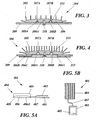
- Fig. 3 is illustrated a further embodiment of a heat sink 204 that is similar to the previously illustrated embodiments, except that it is provided with two grooves 208A and 208B having different size to allow for the flexibility of using heat pipes 207A and 207B of different size.
- this embodiment of the heat sink 204 is also used to exemplify that the heat sinks of the provided range may differ in the height of the cooling fins 205 extending from the main body 306 as well as in the pitch between the fins 205.
- the height of the fins 205 may be chosen depending on board pitch in a rack and the pitch between the fins 305 may be chosen depending on the available air speed.
- Fig. 4 is illustrated an alternative embodiment using a heat sink 304 that consists of two main body parts 306B and 306C of which the upper part 306B carries the cooling fins 305 on an upper surface and the heat pipe receiving grooves 308A-B on its lower surface 306A.
- the second heat sink part 306C is provided on the back of the printed circuit board 309 and is secured to the upper heat sink part 306B by means of a bolt 310 or other appropriate fastener.
- a bolt 310 or other appropriate fastener.
- the heat pipe should then be squeezed between the two parts 306B, 306C of the heat sink 304 in the illustrated manner. This provides for the best thermal connectivity.
- an upper surface of the lower heat sink part 306C is provided with bosses 312 for contacting the backside of the circuit board 309.
- bosses 312 for contacting the backside of the circuit board 309.
- an S-shaped curved heat pipe 407 is used to transfer heat from the heat generating component 403 and the heat collector 402 and to the heat sink 404.
- Such an S-shaped heat pipe 407 will block less air and will also make it possible to employ the same heat pipe for components having different height. It will also assist in absorbing vibration and shock.
- the heat pipes may be provided in the same direction as the airflow, which will allow for the advantageous manufacturing of the heat sinks from extruded aluminum.
- the grooves in the bottom surface of the heat sinks are preferably extended parallel to the heat sink cooling fins, which will allow for the extrusion of the heat sinks with the grooves. Any other orientation of the grooves would require subsequent machining of the grooves or casting of the entire heat sinks. Such alternatives would result in higher manufacturing costs and higher tooling costs, respectively.
- a single aluminum profile can be used for achieving heat sink solutions for a wide power range. The profile is then cut up in several modular sizes so that heat sinks of different modular size may be combined for specific applications having specific cooling requirements.
- Figs. 6A, 6B and 6C illustrate that in addition to the previously illustrated embodiments employing curved heat pipes, the cooling assembly 501, 601, 701 of the invention may naturally also be formed using one or several straight heat pipes 507, 607A, 607B and 707A, 707B, respectively.
- Figs. 6C-6E is likewise illustrated that more than one heat sink 704A, 704B, 804A-C and 904A-D may be mounted along the same heat pipe or heat pipes 707A-B, 807A-B and 907A-B, respectively.
- Figs. 6D and 6E also illustrate the use of U-shaped heat pipes 807A-B and 907A-B, respectively, having heat sinks at both ends to double the cooling capacity.
- Figs 6F and 6G illustrate that the cooling assembly 1001 and 1101, respectively of the invention may be used for cooling several heat generating components 1003A, 1003B and 1103A, 1103B, respectively.
- heat is transferred from two heat-generating electronic components 1003A, 1003B; 1103A, 1103B and to a common heat sink 1004 and 1104, respectively, by separate heat pipes 1007A, 1007B; 1107A, 1107B.
- curved and or S-shaped heat pipes 1007A-B and 1107A-B are preferably used.
- FIGs. 7A-B schematically illustrate examples of further variations of the heat sink modules 1204, 1304 of the cooling assembly according to the invention.
- the heat sink 1204, 1304 is formed having a body 1206, 1306 that is thicker in the area where the heat pipes are located and thinner in all other areas.
- this variant may be applied to heat sinks 1204, 1304 having one or several grooves for receiving the corresponding heat pipes.
- Such variants are well suited for the above discussed extrusion of the heat sinks, since the costs for making an extrusion die even for a rather complex cross-section shape, is very reasonable.
- heat plane is similar in function to a heat pipe. Heat planes can be made very thin, less than 2 mm, one or several such heat planes may be squeezed between a circuit board and the heat sink in a similar way as heat pipes of the invention. Heat planes are much more expensive than heat pipes today but may be considered as an economical alternative in the future.
- the thermal interface material TIM is pre-applied to the grooves of the heat sinks.
- the TIM is also applied to the extruded profile before cutting it up into the individual heat sinks.
- the invention also covers the possibility of providing a range of heat sinks for all applications, said heat sinks being provided with multiple grooves to be prepared for multiple heat pipes, even though only one or a few grooves may be used for a specific application.
- the circuit board can also allow for thermal connection from the heat pipe to the power/ground planes and thereby contribute as an additional area extension.
Landscapes
- Engineering & Computer Science (AREA)
- Physics & Mathematics (AREA)
- Mechanical Engineering (AREA)
- General Engineering & Computer Science (AREA)
- Thermal Sciences (AREA)
- Geometry (AREA)
- Microelectronics & Electronic Packaging (AREA)
- Life Sciences & Earth Sciences (AREA)
- Sustainable Development (AREA)
- Cooling Or The Like Of Electrical Apparatus (AREA)
- Cooling Or The Like Of Semiconductors Or Solid State Devices (AREA)
- Polarising Elements (AREA)
- Inorganic Insulating Materials (AREA)
- Crystals, And After-Treatments Of Crystals (AREA)
Claims (29)
- Procédé de fabrication d'un assemblage de refroidissement pour refroidir une application d'un ou de plusieurs composants électroniques générateurs de chaleur (3; 103; 403; 503; 603; 703; 803; 903; 1003A, 1003B; 1103A, 1103B) montés sur une carte de circuit imprimé (9; 109; 209; 309; 409; 1209; 1309), en éliminant la chaleur produite par le composant par l'intermédiaire d'au moins un caloduc (7; 107A; 107B; 207A, 207B; 307A, 307B; 407; 507; 607A, 607B; 707A, 707B; 807A, 807B; 907A, 907B; 1007A, 1007B; 1107A, 1107B) placé en contact thermique direct avec un collecteur de chaleur (2; 102; 402; 502; 602; 702; 802; 902; 1002A, 1002B; 1102A, 1102B) fixé sur le composant, et d'au moins un dissipateur thermique (4; 104; 204; 304; 404; 504; 604; 704A, 704B; 804A, 804B, 804C; 904A, 904B, 904C, 904D; 1004; 1104; 1204; 1304) fixé sur la carte de circuit imprimé, distant du composant, ledit au moins un caloduc étant introduit dans une rainure correspondante (8; 108A; 108B; 208A, 208B; 308A, 308B) du dissipateur thermique respectif ou des dissipateurs thermiques respectifs, caractérisé par l'étape de fixation d'un ou de multiples dissipateurs thermiques sur la carte de circuit imprimé, superposés au caloduc respectif ou aux caloducs respectifs, pour fixer ainsi ledit caloduc ou lesdits caloducs entre le dissipateur thermique et la carte de circuit imprimé.
- Procédé selon la revendication 1, caractérisé par l'exécution des étapes ci-dessous:calcul de la capacité de refroidissement requise pour l'application spécifique;fourniture, comme modules, d'une gamme standard de tailles et de modèles de dissipateurs thermiques;sélection individuelle, pour ladite application, sur la base dudit calcul de la capacité de refroidissement requise, d'au moins un dissipateur thermique (4; 104; 204; 304; 404; 504; 604; 704A, 704B; 804A, 804B, 804C; 904A, 904B, 904C, 904D; 1004; 1104; 1204; 1304) dans ladite gamme standard de tailles et de modèles de dissipateurs thermiques.
- Procédé selon la revendication 2, caractérisé par les étapes ci-dessous:fourniture, comme modules, d'une autre gamme standard de tailles et de modèles de collecteurs de chaleur et/ou d'une gamme standard de tailles et de modèles de caloducs;sélection individuelle, pour ladite application, sur la base dudit calcul de la capacité de refroidissement requise:d'un collecteur de chaleur (2; 102; 402; 502; 602; 702; 802; 902; 1002A, 1002B; 1102A, 1102B) pour chaque composant électronique générateur de chaleur (3; 103; 403; 503; 603; 703; 803; 903; 1003A, 1003B; 1103A, 1103B) dans ladite gamme standard de tailles et de modèles de collecteurs de chaleur; et/oud'au moins un caloduc (7; 107A; 107B; 207A, 207B; 307A, 307B; 407; 507; 607A, 607B; 707A, 707B; 807A, 807B; 907A, 907B; 1007A, 1007B; 1107A, 1107B) dans ladite gamme standard de tailles et de modèles de caloducs.
- Procédé selon l'une quelconque des revendications 1 à 3, caractérisé par l'étape de serrage de chaque caloduc (7; 107A; 107B; 207A, 207B; 307A, 307B; 407; 507; 607A, 607B; 707A, 707B; 807A, 807B; 907A, 907B; 1007A, 1007B; 1107A, 1107B) entre la carte de circuit imprimé (9; 109; 209; 309; 409; 1209; 1309) et une rainure respective (8; 108A; 108B; 208A, 208B; 308A, 308B) formée dans une surface (6A; 106A; 206A; 306A; 406A) du dissipateur thermique respectif (4; 104; 204; 304; 404; 504; 604; 704A, 704B; 804A, 804B, 804C; 904A, 904B, 904C, 904D; 1004; 1104; 1204; 1304) qui fait face à la carte de circuit imprimé dans l'état fixé.
- Procédé selon la revendication 4, caractérisé par les étapes de formation d'une rainure continue (8) dans une surface inférieure (6A; 406A) d'au moins un dissipateur thermique (4; 404; 504; 1204) de ladite gamme standard de tailles et de modèles de dissipateurs thermiques, d'extension de la rainure au-dessus de l'ensemble de la surface inférieure dudit dissipateur thermique, d'une extrémité vers son extrémité opposée, et de fixation d'un nombre optimal de ces dissipateurs thermiques sur la carte de circuit imprimé (9; 409; 1209), superposés à un caloduc respectif (7; 407; 507), pour fixer ainsi le caloduc respectif sur la carte de circuit imprimé.
- Procédé selon les revendications 4 ou 5, caractérisé par les étapes de formation de plusieurs rainures continues (108A, 108B; 208A, 208B) dans une surface inférieure (106A; 206A) d'au moins un dissipateur thermique (104; 204; 604; 704A, 704B; 804A, 804B, 804C; 904A, 904B, 904C, 904D; 1004; 1104; 1304) de ladite gamme standard de tailles et de modèles de dissipateurs thermiques, d'extension des rainures au-dessus de l'ensemble de la surface inférieure dudit dissipateur thermique, d'une extrémité vers son extrémité opposée, et de fixation d'un nombre optimal de ces dissipateurs thermiques sur la carte de circuit imprimé (109; 209; 1309), superposés à un nombre correspondant de caloducs (104; 204; 607A, 607B; 707A, 707B; 807A, 807B; 907A, 907B; 1007A, 1007B, 1107A; 1107B), pour fixer ainsi lesdits caloducs sur la carte de circuit imprimé.
- Procédé selon l'une quelconque des revendications 4 à 6, caractérisé par l'étape de formation de rainures (208A, 208B) de taille différente dans la surface inférieure (206A) du dissipateur thermique (204), pour recevoir ainsi des caloducs (207A, 207B) ayant des dimensions standard différentes.
- Procédé selon l'une quelconque des revendications 2 à 7, caractérisé par les étapes de fourniture, dans ladite gamme standard de tailles et de modèles de dissipateurs thermiques, d'au moins un dissipateur thermique (304) comprenant une partie supérieure (306B) et une partie inférieure (306C), de formation d'au moins une rainure de réception du caloduc (308A, 308B) dans une surface inférieure (306A) de ladite partie supérieure (306B), de positionnement desdites parties sur chaque côté de la carte de circuit imprimé (309), ladite partie supérieure superposée à au moins un caloduc (307A, 307B) étant reçue dans la rainure respective (308A, 308B), et d'interconnexion desdites parties du dissipateur thermique avec au moins un caloduc serré entre la partie supérieure et la carte de circuit imprimé.
- Procédé selon l'une quelconque des revendications 2 à 8, caractérisé par l'étape de sélection de caloducs individuels (7; 107A; 107B; 207A, 207B; 307A, 307B; 407; 507; 607A, 607B; 707A, 707B; 807A, 807B; 907A, 907B; 1007A, 1007B; 1107A, 1107B) dans une gamme standard de caloducs, englobant des caloducs (7; 107A, 107B; 1007A, 1007B) comportant une partie courbée et/ou des caloducs en forme de U (807A, 807B; 907A, 907B) et/ou de caloducs en forme de S (407; 1107A, 1107B).
- Procédé selon l'une quelconque des revendications 1 à 9, caractérisé en ce que les caloducs (7; 107A; 107B; 207A, 207B; 307A, 307B; 407; 507; 607A, 607B; 707A, 707B; 807A, 807B; 907A, 907B; 1007A, 1007B; 1107A, 1107B) sont placés en contact thermique direct avec la carte de circuit imprimé (9; 109; 209; 309; 409; 1209; 1309).
- Procédé selon l'une quelconque des revendications 1 à 10, caractérisé par l'étape d'application préalable d'un matériau d'interface thermique (11; 111; 211; 311) sur les rainures (8; 108A, 108B; 208A, 208B; 308A, 308B) des dissipateurs thermiques (4; 104; 204; 304; 404; 504; 604; 704A, 704B; 804A, 804B, 804C; 904A, 904B, 904C, 904D; 1004; 1104; 1204; 1304) avant leur fixation sur la carte de circuit imprimé (9; 109; 209; 309; 409; 1209; 1309).
- Procédé selon l'une quelconque des revendications 2 à 11, caractérisé par l'étape de formation d'une gamme standard de dissipateurs thermiques (4; 104; 204; 304; 404; 504; 604; 704A, 704B; 804A, 804B, 804C; 904A, 904B, 904C, 904D; 1004; 1104; 1204; 1304) à partir d'un seul profilé de matériau métallique, en coupant ledit profilé en longueurs différentes.
- Procédé selon la revendication 12, caractérisé par les étapes d'extension des rainures (8; 108A, 108B; 208A, 208B; 308A, 308B) des dissipateurs thermiques (4; 104; 204; 304; 404; 504; 604; 704A, 704B; 804A, 804B, 804C; 904A, 904B, 904C, 904D; 1004; 1104; 1204; 1304) parallèlement à des ailettes de refroidissement (5; 105; 205; 305; 1205; 1305) des dissipateurs thermiques et de fabrication des dissipateurs thermiques avec les rainures par extrusion.
- Procédé selon l'une quelconque des revendications 1 à 13, caractérisé par l'étape de transfert de chaleur de multiples composants électroniques générateurs de chaleur (1003A, 1003B; 1103A, 1103B) vers un dissipateur thermique commun (1004; 1104).
- Assemblage de refroidissement (1; 101; 401; 501; 601; 701; 801; 901; 1001; 1101), pour refroidir une application d'un ou de plusieurs composants générateurs de chaleur (3; 103; 403; 503; 603; 703; 803; 903; 1003A, 1003B; 1103A, 1103B) montés sur une carte de circuit imprimé (9; 109; 209; 309; 409; 1209; 1309), englobant un collecteur de chaleur (2; 102; 402; 502; 602; 702; 802; 902; 1002A, 1002B; 1102A, 1102B) fixé sur un composant électronique générateur de chaleur, un ou plusieurs caloducs (7; 107A; 107B; 207A, 207B; 307A, 307B; 407; 507; 607A, 607B; 707A, 707B; 807A, 807B; 907A, 907B; 1007A, 1007B; 1107A, 1107B) pour éliminer la chaleur produite par les composants, et placés en contact thermique direct avec les collecteurs de chaleur respectifs, et un ou plusieurs dissipateurs thermiques (4; 104; 204; 304; 404; 504; 604; 704A, 704B; 804A, 804B, 804C; 904A, 904B, 904C, 904D; 1004; 1104; 1204; 1304) fixés sur la carte de circuit imprimé, distants des composants, ledit au moins un caloduc étant introduit dans une rainure correspondante (8; 108A, 108B; 208A, 208B; 308A, 308B) des dissipateurs thermiques respectifs, caractérisé en ce qu'un ou de multiples dissipateurs thermiques sont fixés sur la carte de circuit imprimé, superposés au caloduc respectif ou aux caloducs respectifs, pour fixer ainsi ledit caloduc ou lesdits caloducs entre le dissipateur thermique et la carte de circuit imprimé.
- Assemblage de refroidissement (1; 101; 401; 501; 601; 701; 801; 901; 1001; 1101) selon la revendication 15, caractérisé par au moins un dissipateur thermique (4; 104; 204; 304; 404; 504; 604; 704A, 704B; 804A, 804B, 804C; 904A, 904B, 904C, 904D; 1004; 1104; 1204; 1304) fixé sur la carte de circuit imprimé (9; 109; 209; 309; 409; 1209; 1309) et sélectionné individuellement pour ladite application, sur la base d'un calcul de la capacité de refroidissement requise, dans une gamme standard de tailles et de modèles de dissipateurs thermiques.
- Assemblage de refroidissement (1; 101; 401; 501; 601; 701; 801; 901; 1001; 1101) selon la revendication 16, caractérisé par un collecteur de chaleur (2; 102; 402; 502; 602; 702; 802; 902; 1002A, 1002B; 1102A, 1102B) fixé sur chaque composant électronique générateur de chaleur (3; 103; 403; 503; 603; 703; 803; 903; 1003A, 1003B; 1103A, 1103B) et sélectionné individuellement pour ladite application, sur la base d'un calcul de la capacité de refroidissement requise, dans une gamme standard de tailles et de modèles de collecteurs et chaleur et/ou par au moins un caloduc (7; 107A; 107B; 207A, 207B; 307A, 307B; 407; 507; 607A, 607B; 707A, 707B; 807A, 807B; 907A, 907B; 1007A, 1007B; 1107A, 1107B) fixé sur la carte de circuit imprimé (9; 109; 209; 309; 409; 1209; 1309) et sélectionné individuellement pour ladite application, sur la base d'un calcul de la capacité de refroidissement requise, dans une gamme standard de tailles et de modèles de caloducs.
- Assemblage de refroidissement (1; 101; 401; 501; 601; 701; 801; 901; 1001; 1101) selon les revendications 16 ou 17, caractérisé en ce que ladite gamme standard de tailles et de modèles de dissipateurs thermiques comprend au moins un dissipateur thermique (4; 404; 504; 1204) comportant une rainure continue (8) formée dans sa surface inférieure (6A; 406A), et en ce que la rainure s'étend au-dessus de l'ensemble de la surface inférieure dudit dissipateur thermique, d'une extrémité vers son extrémité opposée.
- Assemblage de refroidissement (1; 101; 401; 501; 601; 701; 801; 901; 1001; 1101) selon l'une quelconque des revendications 16 à 18, caractérisé en ce que ladite gamme standard de tailles et de modèles de dissipateurs thermiques comprend au moins un dissipateur thermique (104; 204; 604; 704A, 704B; 804A, 804B, 804C; 904A, 904B, 904C, 904D; 1004; 1104; 1304) comportant plusieurs rainures continues (108A, 108B; 208A, 208B) formées dans sa surface inférieure (106A; 206A), et en ce que les rainures s'étendent au-dessus de l'ensemble de la surface inférieure dudit dissipateur thermique, d'une extrémité vers son extrémité opposée.
- Assemblage de refroidissement (1; 101; 401; 501; 601; 701; 801; 901; 1001; 1101) selon l'une quelconque des revendications 16 à 19, caractérisé en ce que ladite gamme standard de tailles et de modèles de dissipateurs thermiques comprend au moins un dissipateur thermique (204) comportant des rainures (208A, 208B) de taille différente formées dans la surface inférieure (206A) du dissipateur thermique (204), pour recevoir ainsi des caloducs (207A, 207B) ayant des dimensions standard différentes.
- Assemblage de refroidissement (1; 101; 401; 501; 601; 701; 801; 901; 1001; 1101) selon l'une quelconque des revendications 16 à 20, caractérisé en ce que chaque caloduc (7; 107A; 107B; 207A, 207B; 307A, 307B; 407; 507; 607A, 607B; 707A, 707B; 807A, 807B; 907A, 907B; 1007A, 1007B; 1107A, 1107B) de l'assemblage est fixé sur la carte de circuit imprimé (9; 109; 209; 309; 409; 1209; 1309) par serrage entre la carte de circuit imprimé et une rainure respective (8; 108A, 108B; 208A, 208B; 308A, 308B) dans la surface inférieure (6A; 106A; 206A; 306A; 406A) du dissipateur thermique respectif (4; 104; 204; 304; 404; 504; 604; 704A, 704B; 804A, 804B, 804C; 904A, 904B, 904C, 904D; 1004; 1104; 1204; 1304) qui fait face à la carte de circuit imprimé dans un état fixé.
- Assemblage de refroidissement (1; 101; 401; 501; 601; 701; 801; 901; 1001; 1101) selon l'une quelconque des revendications 16 à 21, caractérisé en ce que ladite gamme standard de tailles et de modèles de dissipateurs thermiques comprend au moins un dissipateur thermique (304) comprenant une partie supérieure (306B) et une partie inférieure (306C), et comportant au moins une rainure de réception d'un caloduc (308A, 308B) formée dans une surface inférieure (306A) de ladite partie supérieure (306B), lesdites parties étant destinées à être positionnées sur chaque côté de la carte de circuit imprimé (309), ladite partie supérieure superposée à au moins un caloduc (307A, 307B) étant reçue dans la rainure respective (308A, 308B) et ledit au moins un caloduc étant serré entre la partie supérieure et la carte de circuit imprimé dans l'état interconnecté par lesdites parties du dissipateur thermique.
- Assemblage de refroidissement (1; 101; 401; 501; 601; 701; 801; 901; 1001; 1101) selon l'une quelconque des revendications 16 à 22, caractérisé en ce que ladite gamme standard de caloducs englobe des caloducs (7; 107A, 107B; 1007A, 1007B) comportant une partie courbée et/ou des caloducs en forme de U (807A, 807B; 907A, 907B) et/ou des caloducs en forme de S (407; 1107A; 1107B).
- Assemblage de refroidissement (1; 101; 401; 501; 601; 701; 801; 901; 1001; 1101) selon l'une quelconque des revendications 16 à 23, caractérisé en ce que les caloducs (7; 107A; 107B; 207A, 207B; 307A, 307B; 407; 507; 607A, 607B; 707A, 707B; 807A, 807B; 907A, 907B; 1007A, 1007B; 1107A, 1107B) sont en contact thermique direct avec la carte de circuit imprimé (9; 109; 209; 309; 409; 1209; 1309).
- Assemblage de refroidissement (1; 101; 401; 501; 601; 701; 801; 901; 1001; 1101) selon l'une quelconque des revendications 16 à 24, caractérisé par un matériau d'interface thermique (11; 111; 211; 311) appliqué au préalable dans les rainures (8; 108A, 108B; 208A, 208B; 308A, 308B) des dissipateurs thermiques (4; 104; 204; 304; 404; 504; 604; 704A, 704B; 804A, 804B, 804C; 904A, 904B, 904C, 904D; 1004; 1104; 1204; 1304) avant leur fixation sur la carte de circuit imprimé (9; 109; 209; 309; 409; 1209; 1309).
- Assemblage de refroidissement (1; 101; 401; 501; 601; 701; 801; 901; 1001; 1101) selon l'une quelconque des revendications 16 à 25, caractérisé en ce que ladite gamme standard de dissipateurs thermiques (4; 104; 204; 304; 404; 504; 604; 704A, 704B; 804A, 804B, 804C; 904A, 904B, 904C, 904D; 1004; 1104; 1204; 1304) comprend des dissipateurs thermiques coupés en des longueurs différentes à partir d'un seul profilé de matériau métallique.
- Assemblage de refroidissement (1; 101; 401; 501; 601; 701; 801; 901; 1001; 1101) selon la revendication 26, caractérisé en ce que les rainures (8; 108A, 108B; 208A, 208B; 308A, 308B) dans les dissipateurs thermiques (4; 104; 204; 304; 404; 504; 604; 704A, 704B; 804A, 804B, 804C; 904A, 904B, 904C, 904D; 1004; 1104; 1204; 1304) sont étendues parallèlement à des ailes de refroidissement (5; 105; 205; 305; 1205; 1305) des dissipateurs thermiques, et en ce que les dissipateurs thermiques sont extrudés avec les rainures.
- Assemblage de refroidissement (1; 101; 401; 501; 601; 701; 801; 901; 1001; 1101) selon l'une quelconque des revendications 16 à 27, caractérisé en ce que de multiples composants électroniques générateurs de chaleur (1003A, 1003B; 1103A, 1103B) sont connectés à un dissipateur thermique commun (1004; 1104) par des caloducs séparés (1007A, 1007B; 1107A, 1107B).
- Procédé de conception d'un assemblage de refroidissement (1; 101; 401; 501; 601; 701; 801; 901; 1001; 1101) pour refroidir une application d'un ou de plusieurs composants électroniques générateurs de chaleur (3; 103; 403; 503; 603; 703; 803; 903;1003A, 1003B; 1103A, 1103B) montés sur une carte de circuit imprimé (9; 109; 209; 309; 409; 1209; 1309), en éliminant la chaleur produite par le composant par l'intermédiaire d'au moins un caloduc (7; 107A; 107B; 207A, 207B; 307A, 307B; 407; 507; 607A, 607B; 707A, 707B; 807A, 807B; 907A, 907B; 1007A, 1007B; 1107A, 1107B) placé en contact thermique direct avec un collecteur de chaleur (2; 102; 402; 502; 602; 702; 802; 902; 1002A, 1002B; 1102A, 1102B) fixé sur le composant, et d'au moins un dissipateur thermique (4; 104; 204; 304; 404; 504; 604; 704A, 704B; 804A, 804B, 804C; 904A, 904B, 904C, 904D; 1004; 1104; 1204; 1304) fixé sur la carte de circuit imprimé, distante du composant, ledit au moins un caloduc étant introduit dans une rainure correspondante (8; 108A, 108B; 208A, 208B; 308A, 308B) du dissipateur thermique respectif ou des dissipateurs thermiques respectifs, caractérisé par les étapes ci-dessous:calcul de la capacité de refroidissement requise pour l'application spécifique;sélection individuelle, pour ladite application, et sur la base dudit calcul de la capacité de refroidissement requise, d'un collecteur de chaleur (2; 102; 402; 502; 602; 702; 802; 902; 1002A, 1002B; 1102A, 1102B) pour chaque composant électronique générateur de chaleur (3; 103; 403; 503; 603; 703; 803; 903; 1003A, 1003B; 1103A, 1103B), dans une gamme standard de tailles et de modèles de collecteurs de chaleur;sélection individuelle, pour ladite application, et sur la base dudit calcul de la capacité de refroidissement requise, d'au moins un caloduc (7; 107A; 107B; 207A, 207B; 307A, 307B; 407; 507; 607A, 607B; 707A, 707B; 807A, 807B; 907A, 907B; 1007A, 1007B; 1107A, 1107B) dans une gamme standard de tailles et de modèles de caloducs; et par l'étape ci-dessous:sélection individuelle, pour ladite application, et sur la base dudit calcul de la capacité de refroidissement requise, d'au moins un dissipateur thermique (4; 104; 204; 304; 404; 504; 604; 704A, 704B; 804A, 804B, 804C; 904A, 904B, 904C, 904D; 1004; 1104; 1204; 1304) dans une gamme standard de tailles et de modèles de dissipateurs thermiques, en vue de leur fixation comme modules sur la carte de circuit imprimé, superposés au caloduc respectif ou aux caloducs respectifs, pour fixer ainsi ledit caloduc ou lesdits caloducs entre le dissipateur thermique et la carte de circuit imprimé.
Applications Claiming Priority (1)
| Application Number | Priority Date | Filing Date | Title |
|---|---|---|---|
| PCT/SE2005/001008 WO2006137763A1 (fr) | 2005-06-23 | 2005-06-23 | Ensemble de refroidissement |
Publications (2)
| Publication Number | Publication Date |
|---|---|
| EP1900265A1 EP1900265A1 (fr) | 2008-03-19 |
| EP1900265B1 true EP1900265B1 (fr) | 2010-08-04 |
Family
ID=37570708
Family Applications (1)
| Application Number | Title | Priority Date | Filing Date |
|---|---|---|---|
| EP05754987A Expired - Lifetime EP1900265B1 (fr) | 2005-06-23 | 2005-06-23 | Ensemble de refroidissement |
Country Status (8)
| Country | Link |
|---|---|
| US (1) | US7545646B2 (fr) |
| EP (1) | EP1900265B1 (fr) |
| JP (1) | JP2008547216A (fr) |
| CN (1) | CN101209006A (fr) |
| AT (1) | ATE476864T1 (fr) |
| CA (1) | CA2611578A1 (fr) |
| DE (1) | DE602005022783D1 (fr) |
| WO (1) | WO2006137763A1 (fr) |
Families Citing this family (20)
| Publication number | Priority date | Publication date | Assignee | Title |
|---|---|---|---|---|
| AU2006344681A1 (en) * | 2006-05-30 | 2007-12-21 | Neobulb Technologies, Inc. | High-power and high heat-dissipating light emitting diode illuminating equipment |
| US20080264608A1 (en) * | 2007-04-30 | 2008-10-30 | Trentent Tye | Cooling mechanism comprising a heat pipe and water block |
| US8622588B2 (en) * | 2008-04-29 | 2014-01-07 | Koninklijke Philips N.V. | Light emitting module, heat sink and illumination system |
| US20110048677A1 (en) * | 2009-08-31 | 2011-03-03 | Kuo-Len Lin | Heat-conducting assembly for heat pipes of different diameters and heat sink having the same |
| US20110232877A1 (en) * | 2010-03-23 | 2011-09-29 | Celsia Technologies Taiwan, Inc. | Compact vapor chamber and heat-dissipating module having the same |
| US9036353B2 (en) | 2012-11-26 | 2015-05-19 | Northrop Grumman Systems Corporation | Flexible thermal interface for electronics |
| CN103415184A (zh) * | 2013-07-23 | 2013-11-27 | 苏州天脉导热科技有限公司 | 一种热传递与热扩散器件的结合方法 |
| KR102173141B1 (ko) * | 2014-02-04 | 2020-11-02 | 삼성전자주식회사 | 히트 파이프를 포함하는 휴대 장치 |
| JP6486965B2 (ja) * | 2014-06-04 | 2019-03-20 | ホアウェイ・テクノロジーズ・カンパニー・リミテッド | 電子デバイス |
| US9750127B2 (en) | 2015-12-04 | 2017-08-29 | General Electric Company | Circuit card assembly including heat transfer assembly and method of manufacturing such |
| US10119759B2 (en) * | 2016-03-31 | 2018-11-06 | Hoya Candeo Optronics Corporation | Heat radiating apparatus and light illuminating apparatus with the same |
| US11543188B2 (en) | 2016-06-15 | 2023-01-03 | Delta Electronics, Inc. | Temperature plate device |
| US11306974B2 (en) * | 2016-06-15 | 2022-04-19 | Delta Electronics, Inc. | Temperature plate and heat dissipation device |
| WO2018053005A1 (fr) * | 2016-09-16 | 2018-03-22 | Heraeus Noblelight America Llc | Dissipateur thermique comprenant une couche de film épais pour réseaux de led uv, et procédés de formation de réseaux de led uv |
| EP3301999B1 (fr) * | 2016-09-30 | 2020-06-17 | HP Scitex Ltd | Dissipateur thermique à diode électroluminescente |
| US9894803B1 (en) | 2016-11-18 | 2018-02-13 | Abaco Systems, Inc. | Thermal sink with an embedded heat pipe |
| TWI685638B (zh) * | 2018-09-14 | 2020-02-21 | 財團法人工業技術研究院 | 立體脈衝式熱管、立體脈衝式熱管組和散熱模組 |
| US10667378B1 (en) * | 2019-01-14 | 2020-05-26 | Eagle Technology, Llc | Electronic assemblies having embedded passive heat pipes and associated method |
| JPWO2024085050A1 (fr) * | 2022-10-17 | 2024-04-25 | ||
| WO2024085051A1 (fr) * | 2022-10-17 | 2024-04-25 | 京セラ株式会社 | Substrat de dissipation de chaleur et dispositif de dissipation de chaleur |
Family Cites Families (20)
| Publication number | Priority date | Publication date | Assignee | Title |
|---|---|---|---|---|
| JPS5461673A (en) * | 1977-10-25 | 1979-05-18 | Oki Electric Ind Co Ltd | Printed circuit board for radiation |
| JPS5715609A (en) * | 1980-06-27 | 1982-01-27 | Toshiba Corp | Machining method and its device for turbine blade |
| JPS5748699A (en) * | 1980-09-08 | 1982-03-20 | Japan Gasoline | Method of treating liquid containing radioactive nuclide |
| EP0353568A1 (fr) * | 1988-07-26 | 1990-02-07 | Siemens Aktiengesellschaft | Procédé pour réduire des perturbations d'image de produisant lors d'une reproduction de bandes magnétiques vidéo dans des enregistreurs vidéo et dispositif de mise en oeuvre du procédé |
| JPH0370968U (fr) * | 1989-11-15 | 1991-07-17 | ||
| US5353192A (en) * | 1993-02-08 | 1994-10-04 | At&T Bell Laboratories | Circuit card assembly |
| JPH07176661A (ja) * | 1993-12-20 | 1995-07-14 | Hitachi Cable Ltd | ヒートシンク |
| JP3414996B2 (ja) * | 1997-09-01 | 2003-06-09 | 株式会社Pfu | 基板実装型熱交換構造 |
| TW450381U (en) * | 1998-08-07 | 2001-08-11 | Foxconn Prec Components Co Ltd | Heat sink device |
| JP4493117B2 (ja) * | 1999-03-25 | 2010-06-30 | レノボ シンガポール プライヴェート リミテッド | ノートブック型パーソナルコンピューターの冷却方法及び冷却装置 |
| JP4223628B2 (ja) * | 1999-05-20 | 2009-02-12 | ティーエス ヒートロニクス 株式会社 | 電子機器冷却装置 |
| JP3982947B2 (ja) * | 1999-05-26 | 2007-09-26 | 株式会社フジクラ | ヒートシンクの固定構造 |
| US6639799B2 (en) * | 2000-12-22 | 2003-10-28 | Intel Corporation | Integrated vapor chamber heat sink and spreader and an embedded direct heat pipe attachment |
| JP3637304B2 (ja) * | 2001-11-29 | 2005-04-13 | 株式会社東芝 | 小型電子機器 |
| JP2003218294A (ja) * | 2002-01-23 | 2003-07-31 | Mitsubishi Electric Corp | 放熱器 |
| JP2003229689A (ja) * | 2002-02-04 | 2003-08-15 | Fujikura Ltd | 電子素子の冷却装置 |
| JP2004022786A (ja) * | 2002-06-17 | 2004-01-22 | Matsushita Electric Ind Co Ltd | ファンユニット |
| US7057895B2 (en) * | 2003-06-30 | 2006-06-06 | Intel Corporation | Thermal standoff for close proximity thermal management |
| JP4041023B2 (ja) * | 2003-07-04 | 2008-01-30 | 株式会社東芝 | 配線基板 |
| CN100377343C (zh) * | 2004-09-21 | 2008-03-26 | 鸿富锦精密工业(深圳)有限公司 | 散热装置的制造方法 |
-
2005
- 2005-06-23 WO PCT/SE2005/001008 patent/WO2006137763A1/fr not_active Ceased
- 2005-06-23 CN CNA2005800502168A patent/CN101209006A/zh active Pending
- 2005-06-23 CA CA002611578A patent/CA2611578A1/fr not_active Abandoned
- 2005-06-23 JP JP2008518065A patent/JP2008547216A/ja active Pending
- 2005-06-23 AT AT05754987T patent/ATE476864T1/de not_active IP Right Cessation
- 2005-06-23 EP EP05754987A patent/EP1900265B1/fr not_active Expired - Lifetime
- 2005-06-23 US US11/917,669 patent/US7545646B2/en not_active Expired - Lifetime
- 2005-06-23 DE DE602005022783T patent/DE602005022783D1/de not_active Expired - Lifetime
Also Published As
| Publication number | Publication date |
|---|---|
| CA2611578A1 (fr) | 2006-12-28 |
| DE602005022783D1 (de) | 2010-09-16 |
| CN101209006A (zh) | 2008-06-25 |
| WO2006137763A1 (fr) | 2006-12-28 |
| EP1900265A1 (fr) | 2008-03-19 |
| ATE476864T1 (de) | 2010-08-15 |
| US20080198554A1 (en) | 2008-08-21 |
| US7545646B2 (en) | 2009-06-09 |
| JP2008547216A (ja) | 2008-12-25 |
Similar Documents
| Publication | Publication Date | Title |
|---|---|---|
| EP1900265B1 (fr) | Ensemble de refroidissement | |
| US4884631A (en) | Forced air heat sink apparatus | |
| US6305463B1 (en) | Air or liquid cooled computer module cold plate | |
| CN101573017B (zh) | 散热装置 | |
| US5986882A (en) | Electronic apparatus having removable processor/heat pipe cooling device modules therein | |
| US7319588B2 (en) | Heat dissipation device | |
| US6712129B1 (en) | Heat dissipation device comprised of multiple heat sinks | |
| US6871702B2 (en) | Heat dissipator | |
| RU2004127135A (ru) | Устройство охлаждения микросхем графического видеоадаптера | |
| US20040188132A1 (en) | Printed Circuit Board with Isolated Metallic Substrate Comprising an Integrated Cooling System | |
| EP0285779A2 (fr) | Système de refroidissement pour modules de dispositifs à semi-conducteurs | |
| US20070279872A1 (en) | Heat dissipation device | |
| CN100403529C (zh) | 用于高密度封装应用的高性能气冷式散热器和其形成方法 | |
| TW200836615A (en) | Liquid-based cooling system for cooling a multi-component electronics system | |
| CN101212884B (zh) | 散热装置 | |
| US7530388B2 (en) | Heat sink | |
| US6684501B2 (en) | Foil heat sink and a method for fabricating same | |
| US7726385B2 (en) | Heat dissipation interface for semiconductor chip structures | |
| US6089315A (en) | Composite heat sink | |
| US20110048677A1 (en) | Heat-conducting assembly for heat pipes of different diameters and heat sink having the same | |
| US20050121172A1 (en) | Composite heatsink for cooling of heat-generating element | |
| US20070133177A1 (en) | Flexing chip heatsink | |
| EP2161527B1 (fr) | Procédé et assemblage pour des sections d'évaporateur à connexion par affleurement de caloducs juxtaposés sur une base fixe | |
| EP2284885B1 (fr) | Ailette à dissipation de chaleur capable d'augmenter la zone de dissipation de chaleur, dissipateur de chaleur doté de ces ailettes de dissipation de chaleur, et son procédé de fabrication | |
| CN101616567A (zh) | 散热装置 |
Legal Events
| Date | Code | Title | Description |
|---|---|---|---|
| PUAI | Public reference made under article 153(3) epc to a published international application that has entered the european phase |
Free format text: ORIGINAL CODE: 0009012 |
|
| 17P | Request for examination filed |
Effective date: 20080116 |
|
| AK | Designated contracting states |
Kind code of ref document: A1 Designated state(s): AT BE BG CH CY CZ DE DK EE ES FI FR GB GR HU IE IS IT LI LT LU MC NL PL PT RO SE SI SK TR |
|
| DAX | Request for extension of the european patent (deleted) | ||
| GRAP | Despatch of communication of intention to grant a patent |
Free format text: ORIGINAL CODE: EPIDOSNIGR1 |
|
| GRAS | Grant fee paid |
Free format text: ORIGINAL CODE: EPIDOSNIGR3 |
|
| GRAA | (expected) grant |
Free format text: ORIGINAL CODE: 0009210 |
|
| AK | Designated contracting states |
Kind code of ref document: B1 Designated state(s): AT BE BG CH CY CZ DE DK EE ES FI FR GB GR HU IE IS IT LI LT LU MC NL PL PT RO SE SI SK TR |
|
| REG | Reference to a national code |
Ref country code: GB Ref legal event code: FG4D |
|
| REG | Reference to a national code |
Ref country code: CH Ref legal event code: EP |
|
| REG | Reference to a national code |
Ref country code: IE Ref legal event code: FG4D |
|
| REF | Corresponds to: |
Ref document number: 602005022783 Country of ref document: DE Date of ref document: 20100916 Kind code of ref document: P |
|
| REG | Reference to a national code |
Ref country code: NL Ref legal event code: VDEP Effective date: 20100804 |
|
| LTIE | Lt: invalidation of european patent or patent extension |
Effective date: 20100804 |
|
| PG25 | Lapsed in a contracting state [announced via postgrant information from national office to epo] |
Ref country code: AT Free format text: LAPSE BECAUSE OF FAILURE TO SUBMIT A TRANSLATION OF THE DESCRIPTION OR TO PAY THE FEE WITHIN THE PRESCRIBED TIME-LIMIT Effective date: 20100804 Ref country code: LT Free format text: LAPSE BECAUSE OF FAILURE TO SUBMIT A TRANSLATION OF THE DESCRIPTION OR TO PAY THE FEE WITHIN THE PRESCRIBED TIME-LIMIT Effective date: 20100804 Ref country code: FI Free format text: LAPSE BECAUSE OF FAILURE TO SUBMIT A TRANSLATION OF THE DESCRIPTION OR TO PAY THE FEE WITHIN THE PRESCRIBED TIME-LIMIT Effective date: 20100804 Ref country code: NL Free format text: LAPSE BECAUSE OF FAILURE TO SUBMIT A TRANSLATION OF THE DESCRIPTION OR TO PAY THE FEE WITHIN THE PRESCRIBED TIME-LIMIT Effective date: 20100804 |
|
| PG25 | Lapsed in a contracting state [announced via postgrant information from national office to epo] |
Ref country code: CY Free format text: LAPSE BECAUSE OF FAILURE TO SUBMIT A TRANSLATION OF THE DESCRIPTION OR TO PAY THE FEE WITHIN THE PRESCRIBED TIME-LIMIT Effective date: 20100804 Ref country code: BG Free format text: LAPSE BECAUSE OF FAILURE TO SUBMIT A TRANSLATION OF THE DESCRIPTION OR TO PAY THE FEE WITHIN THE PRESCRIBED TIME-LIMIT Effective date: 20101104 Ref country code: IS Free format text: LAPSE BECAUSE OF FAILURE TO SUBMIT A TRANSLATION OF THE DESCRIPTION OR TO PAY THE FEE WITHIN THE PRESCRIBED TIME-LIMIT Effective date: 20101204 Ref country code: PT Free format text: LAPSE BECAUSE OF FAILURE TO SUBMIT A TRANSLATION OF THE DESCRIPTION OR TO PAY THE FEE WITHIN THE PRESCRIBED TIME-LIMIT Effective date: 20101206 Ref country code: SI Free format text: LAPSE BECAUSE OF FAILURE TO SUBMIT A TRANSLATION OF THE DESCRIPTION OR TO PAY THE FEE WITHIN THE PRESCRIBED TIME-LIMIT Effective date: 20100804 Ref country code: PL Free format text: LAPSE BECAUSE OF FAILURE TO SUBMIT A TRANSLATION OF THE DESCRIPTION OR TO PAY THE FEE WITHIN THE PRESCRIBED TIME-LIMIT Effective date: 20100804 |
|
| PG25 | Lapsed in a contracting state [announced via postgrant information from national office to epo] |
Ref country code: GR Free format text: LAPSE BECAUSE OF FAILURE TO SUBMIT A TRANSLATION OF THE DESCRIPTION OR TO PAY THE FEE WITHIN THE PRESCRIBED TIME-LIMIT Effective date: 20101105 Ref country code: BE Free format text: LAPSE BECAUSE OF FAILURE TO SUBMIT A TRANSLATION OF THE DESCRIPTION OR TO PAY THE FEE WITHIN THE PRESCRIBED TIME-LIMIT Effective date: 20100804 Ref country code: SE Free format text: LAPSE BECAUSE OF FAILURE TO SUBMIT A TRANSLATION OF THE DESCRIPTION OR TO PAY THE FEE WITHIN THE PRESCRIBED TIME-LIMIT Effective date: 20100804 |
|
| PG25 | Lapsed in a contracting state [announced via postgrant information from national office to epo] |
Ref country code: DK Free format text: LAPSE BECAUSE OF FAILURE TO SUBMIT A TRANSLATION OF THE DESCRIPTION OR TO PAY THE FEE WITHIN THE PRESCRIBED TIME-LIMIT Effective date: 20100804 |
|
| PG25 | Lapsed in a contracting state [announced via postgrant information from national office to epo] |
Ref country code: CZ Free format text: LAPSE BECAUSE OF FAILURE TO SUBMIT A TRANSLATION OF THE DESCRIPTION OR TO PAY THE FEE WITHIN THE PRESCRIBED TIME-LIMIT Effective date: 20100804 Ref country code: EE Free format text: LAPSE BECAUSE OF FAILURE TO SUBMIT A TRANSLATION OF THE DESCRIPTION OR TO PAY THE FEE WITHIN THE PRESCRIBED TIME-LIMIT Effective date: 20100804 Ref country code: IT Free format text: LAPSE BECAUSE OF FAILURE TO SUBMIT A TRANSLATION OF THE DESCRIPTION OR TO PAY THE FEE WITHIN THE PRESCRIBED TIME-LIMIT Effective date: 20100804 Ref country code: RO Free format text: LAPSE BECAUSE OF FAILURE TO SUBMIT A TRANSLATION OF THE DESCRIPTION OR TO PAY THE FEE WITHIN THE PRESCRIBED TIME-LIMIT Effective date: 20100804 Ref country code: SK Free format text: LAPSE BECAUSE OF FAILURE TO SUBMIT A TRANSLATION OF THE DESCRIPTION OR TO PAY THE FEE WITHIN THE PRESCRIBED TIME-LIMIT Effective date: 20100804 |
|
| PLBE | No opposition filed within time limit |
Free format text: ORIGINAL CODE: 0009261 |
|
| STAA | Information on the status of an ep patent application or granted ep patent |
Free format text: STATUS: NO OPPOSITION FILED WITHIN TIME LIMIT |
|
| PG25 | Lapsed in a contracting state [announced via postgrant information from national office to epo] |
Ref country code: ES Free format text: LAPSE BECAUSE OF FAILURE TO SUBMIT A TRANSLATION OF THE DESCRIPTION OR TO PAY THE FEE WITHIN THE PRESCRIBED TIME-LIMIT Effective date: 20101115 |
|
| 26N | No opposition filed |
Effective date: 20110506 |
|
| REG | Reference to a national code |
Ref country code: DE Ref legal event code: R097 Ref document number: 602005022783 Country of ref document: DE Effective date: 20110506 |
|
| REG | Reference to a national code |
Ref country code: CH Ref legal event code: PL |
|
| REG | Reference to a national code |
Ref country code: IE Ref legal event code: MM4A |
|
| PG25 | Lapsed in a contracting state [announced via postgrant information from national office to epo] |
Ref country code: CH Free format text: LAPSE BECAUSE OF NON-PAYMENT OF DUE FEES Effective date: 20110630 Ref country code: IE Free format text: LAPSE BECAUSE OF NON-PAYMENT OF DUE FEES Effective date: 20110623 Ref country code: LI Free format text: LAPSE BECAUSE OF NON-PAYMENT OF DUE FEES Effective date: 20110630 |
|
| PG25 | Lapsed in a contracting state [announced via postgrant information from national office to epo] |
Ref country code: MC Free format text: LAPSE BECAUSE OF NON-PAYMENT OF DUE FEES Effective date: 20110630 |
|
| PG25 | Lapsed in a contracting state [announced via postgrant information from national office to epo] |
Ref country code: LU Free format text: LAPSE BECAUSE OF NON-PAYMENT OF DUE FEES Effective date: 20110623 |
|
| PG25 | Lapsed in a contracting state [announced via postgrant information from national office to epo] |
Ref country code: TR Free format text: LAPSE BECAUSE OF FAILURE TO SUBMIT A TRANSLATION OF THE DESCRIPTION OR TO PAY THE FEE WITHIN THE PRESCRIBED TIME-LIMIT Effective date: 20100804 |
|
| PG25 | Lapsed in a contracting state [announced via postgrant information from national office to epo] |
Ref country code: HU Free format text: LAPSE BECAUSE OF FAILURE TO SUBMIT A TRANSLATION OF THE DESCRIPTION OR TO PAY THE FEE WITHIN THE PRESCRIBED TIME-LIMIT Effective date: 20100804 |
|
| REG | Reference to a national code |
Ref country code: FR Ref legal event code: PLFP Year of fee payment: 12 |
|
| PGFP | Annual fee paid to national office [announced via postgrant information from national office to epo] |
Ref country code: DE Payment date: 20160628 Year of fee payment: 12 |
|
| REG | Reference to a national code |
Ref country code: FR Ref legal event code: PLFP Year of fee payment: 13 |
|
| REG | Reference to a national code |
Ref country code: DE Ref legal event code: R119 Ref document number: 602005022783 Country of ref document: DE |
|
| PG25 | Lapsed in a contracting state [announced via postgrant information from national office to epo] |
Ref country code: DE Free format text: LAPSE BECAUSE OF NON-PAYMENT OF DUE FEES Effective date: 20180103 |
|
| REG | Reference to a national code |
Ref country code: FR Ref legal event code: PLFP Year of fee payment: 14 |
|
| PGFP | Annual fee paid to national office [announced via postgrant information from national office to epo] |
Ref country code: FR Payment date: 20210625 Year of fee payment: 17 |
|
| PGFP | Annual fee paid to national office [announced via postgrant information from national office to epo] |
Ref country code: GB Payment date: 20220628 Year of fee payment: 18 |
|
| PG25 | Lapsed in a contracting state [announced via postgrant information from national office to epo] |
Ref country code: FR Free format text: LAPSE BECAUSE OF NON-PAYMENT OF DUE FEES Effective date: 20220630 |
|
| GBPC | Gb: european patent ceased through non-payment of renewal fee |
Effective date: 20230623 |
|
| PG25 | Lapsed in a contracting state [announced via postgrant information from national office to epo] |
Ref country code: GB Free format text: LAPSE BECAUSE OF NON-PAYMENT OF DUE FEES Effective date: 20230623 |