EP1900386B1 - Sicherheitsspritze - Google Patents
Sicherheitsspritze Download PDFInfo
- Publication number
- EP1900386B1 EP1900386B1 EP06254393A EP06254393A EP1900386B1 EP 1900386 B1 EP1900386 B1 EP 1900386B1 EP 06254393 A EP06254393 A EP 06254393A EP 06254393 A EP06254393 A EP 06254393A EP 1900386 B1 EP1900386 B1 EP 1900386B1
- Authority
- EP
- European Patent Office
- Prior art keywords
- needle
- syringe barrel
- seat
- combined
- end opening
- Prior art date
- Legal status (The legal status is an assumption and is not a legal conclusion. Google has not performed a legal analysis and makes no representation as to the accuracy of the status listed.)
- Expired - Lifetime
Links
Images







Classifications
-
- A—HUMAN NECESSITIES
- A61—MEDICAL OR VETERINARY SCIENCE; HYGIENE
- A61M—DEVICES FOR INTRODUCING MEDIA INTO, OR ONTO, THE BODY; DEVICES FOR TRANSDUCING BODY MEDIA OR FOR TAKING MEDIA FROM THE BODY; DEVICES FOR PRODUCING OR ENDING SLEEP OR STUPOR
- A61M5/00—Devices for bringing media into the body in a subcutaneous, intra-vascular or intramuscular way; Accessories therefor, e.g. filling or cleaning devices, arm rests
- A61M5/178—Syringes
- A61M5/31—Details
- A61M5/32—Needles; Details of needles pertaining to their connection with syringe or hub; Accessories for bringing the needle into, or holding the needle on, the body; Devices for protection of needles
- A61M5/3205—Apparatus for removing or disposing of used needles or syringes, e.g. containers; Means for protection against accidental injuries from used needles
- A61M5/321—Means for protection against accidental injuries by used needles
- A61M5/322—Retractable needles, i.e. disconnected from and withdrawn into the syringe barrel by the piston
- A61M5/3234—Fully automatic needle retraction, i.e. in which triggering of the needle does not require a deliberate action by the user
-
- A—HUMAN NECESSITIES
- A61—MEDICAL OR VETERINARY SCIENCE; HYGIENE
- A61M—DEVICES FOR INTRODUCING MEDIA INTO, OR ONTO, THE BODY; DEVICES FOR TRANSDUCING BODY MEDIA OR FOR TAKING MEDIA FROM THE BODY; DEVICES FOR PRODUCING OR ENDING SLEEP OR STUPOR
- A61M5/00—Devices for bringing media into the body in a subcutaneous, intra-vascular or intramuscular way; Accessories therefor, e.g. filling or cleaning devices, arm rests
- A61M5/178—Syringes
- A61M5/31—Details
- A61M5/32—Needles; Details of needles pertaining to their connection with syringe or hub; Accessories for bringing the needle into, or holding the needle on, the body; Devices for protection of needles
- A61M5/3205—Apparatus for removing or disposing of used needles or syringes, e.g. containers; Means for protection against accidental injuries from used needles
- A61M5/321—Means for protection against accidental injuries by used needles
- A61M5/322—Retractable needles, i.e. disconnected from and withdrawn into the syringe barrel by the piston
- A61M5/3234—Fully automatic needle retraction, i.e. in which triggering of the needle does not require a deliberate action by the user
- A61M2005/3241—Needle retraction energy is accumulated inside of a hollow plunger rod
-
- A—HUMAN NECESSITIES
- A61—MEDICAL OR VETERINARY SCIENCE; HYGIENE
- A61M—DEVICES FOR INTRODUCING MEDIA INTO, OR ONTO, THE BODY; DEVICES FOR TRANSDUCING BODY MEDIA OR FOR TAKING MEDIA FROM THE BODY; DEVICES FOR PRODUCING OR ENDING SLEEP OR STUPOR
- A61M5/00—Devices for bringing media into the body in a subcutaneous, intra-vascular or intramuscular way; Accessories therefor, e.g. filling or cleaning devices, arm rests
- A61M5/178—Syringes
- A61M5/31—Details
- A61M5/32—Needles; Details of needles pertaining to their connection with syringe or hub; Accessories for bringing the needle into, or holding the needle on, the body; Devices for protection of needles
- A61M5/3205—Apparatus for removing or disposing of used needles or syringes, e.g. containers; Means for protection against accidental injuries from used needles
- A61M5/321—Means for protection against accidental injuries by used needles
- A61M5/322—Retractable needles, i.e. disconnected from and withdrawn into the syringe barrel by the piston
- A61M5/3234—Fully automatic needle retraction, i.e. in which triggering of the needle does not require a deliberate action by the user
- A61M2005/3241—Needle retraction energy is accumulated inside of a hollow plunger rod
- A61M2005/3242—Needle retraction by vacuum
-
- A—HUMAN NECESSITIES
- A61—MEDICAL OR VETERINARY SCIENCE; HYGIENE
- A61M—DEVICES FOR INTRODUCING MEDIA INTO, OR ONTO, THE BODY; DEVICES FOR TRANSDUCING BODY MEDIA OR FOR TAKING MEDIA FROM THE BODY; DEVICES FOR PRODUCING OR ENDING SLEEP OR STUPOR
- A61M5/00—Devices for bringing media into the body in a subcutaneous, intra-vascular or intramuscular way; Accessories therefor, e.g. filling or cleaning devices, arm rests
- A61M5/50—Devices for bringing media into the body in a subcutaneous, intra-vascular or intramuscular way; Accessories therefor, e.g. filling or cleaning devices, arm rests having means for preventing re-use, or for indicating if defective, used, tampered with or unsterile
- A61M5/508—Means for preventing re-use by disrupting the piston seal, e.g. by puncturing
Definitions
- the present invention generally relates to a safety syringe, and more particularly, relates to a safety syringe that is capable of retracting a needle unit into a syringe barrel of the safety syringe by low pressure.
- FIG. 1 is a schematic diagram of a conventional syringe.
- the conventional syringe 10 includes an outer syringe barrel 1002 with scales on its surface and an internal cavity therein for containing a medical solution, a rod 1004 with a flexible rubber-sealing member 1043, and a needle unit 1003.
- the needle unit 1003 comprises a needle holder 1030 and a needle 1031.
- An opening (not shown) in a front end of the outer syringe barrel 1002 can be mated with an inner screw thread of the needle holder 1030.
- a rear end of the needle 1031 is passed through the needle holder 1030 to communicate with an internal cavity of the outer syringe barrel 1002.
- the rod 1004 can be put into the internal cavity of the outer syringe barrel 1002 via a rear opening 1024 which has a larger cross-sectional area.
- the outside diameter of the flexible rubber-sealing member 1043 is slightly larger than the inside diameter of the outer syringe barrel 1002 so that the medical solution in the syringe can be flowed out from the needle 1031 while the rod 1004 is pushed from the back end thereof.
- medical solutions can be drawn into the syringe by pulling the rod 1004 backwards.
- a safety syringe whose needle can be retrieved automatically is required to prevent the operating staff from infections.
- a hollow inner syringe barrel is generally utilized in the safety syringe to replace the rod of the conventional syringe, so that a needle is automatically retracted into the inner syringe barrel of the safety syringe after injection by way of a mechanism generating an attraction force from the internal cavity of the inner syringe barrel.
- a needle retraction system of a safety syringe is disclosed in an U.S. Patent No.
- a retractable needle medical assembly includes a barrel and a plunger assembly defining an internal passageway within which a retraction member is mounted.
- the retraction member is biased into the passageway, by means of a spring or a vacuum located within the passageway.
- a further example of a safety syringe that is capable of automatically retracting a needle unit into an inner syringe barrel by a low pressure generated from the inner syringe barrel is disclosed in US 2004/0143215 A1 .
- the preamble of claim 1 is based on the disclosure of said document.
- the present invention provides a safety syringe that can overcome the drawbacks of the conventional syringe mentioned above.
- an object of the present invention is to provide a safety syringe that can resist a low-pressure attraction force from an inner syringe barrel during injection.
- a further object of the present invention is to provide a safety syringe with a replaceable needle body to reduce waste from changing another whole new syringe while a needle is damaged.
- a safety syringe which comprises an outer syringe barrel, a flexible seat, a needle unit, an inner syringe barrel, a flexible sealing member, and an anti-compressive structure.
- the outer syringe barrel comprises a front-end opening and a back-end opening.
- the flexible seat can be fitted tightly against an inner wall of the outer syringe barrel.
- the needle unit comprises a needle seat and a needle body connecting to the needle seat, wherein the needle seat can be releasably engaged with the flexible seat.
- the inner syringe barrel comprises a forward end, a backward end, and a hollow body disposed between the forward end and the backward end.
- An opening located in the forward end of the inner syringe barrel has an inside diameter larger than an outside diameter of the needle seat.
- the inner syringe barrel can be inserted into the outer syringe barrel through the back-end opening of the outer syringe barrel.
- the flexible sealing member is locked tightly against an inner wall of the forward end of the inner syringe barrel to seal the opening in the forward end of the inner syringe barrel, and makes the hollow body of the inner syringe barrel a sealed space.
- the anti-compressive structure can be combined with the flexible sealing member, and used to prevent the flexible sealing member from slipping into the hollow body of the inner syringe barrel.
- the sealed space within the hollow body of the inner syringe barrel may be in a low-pressure state.
- the anti-compressive structure can be combined with the needle seat of the needle unit, the flexible seat is further pushed by the forward end of the inner syringe barrel, and then the flexible seat and the needle seat are separated.
- the flexible sealing member is pushed away from the inner wall of the forward end of the inner syringe barrel by a reaction force from the needle unit, and then retracted into the hollow body of the inner syringe barrel.
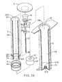
- FIGs. 2A and 2B are cross-sectional views of a safety syringe according to an embodiment of the present invention before and after assembly respectively.
- the safety syringe comprises an outer syringe barrel 2, a flexible seat 3, a needle unit 6, an inner syringe barrel 5, a flexible sealing member 8, and an anti-compressive structure 7.
- the relations and functions of the above major components, and also the other components in the figures will be illustrated in greater detail below.
- the outer syringe barrel 2 comprises a front end 21, a back end 22, and an elongate hollow body 20 between the front end 21 and the back end 22.
- the elongate hollow body 20 can be used to contain a liquid, such as a medical solution, and the front end 21 and the back end 22 respectively comprises a front-end opening 210 and a back-end opening 220.
- the inner syringe barrel 5 can be inserted into the elongate hollow body 20 of the outer syringe barrel 2 through the back-end opening 220. The fluid can be flowed out the safety syringe through the needle unit 6 during injection.
- a combined seat 214 can be disposed adjacent the front end 21 of the outer syringe barrel 2, and the combined seat 214 comprises a through passage 212 communicating with the front-end opening 210 of the outer syringe barrel 2.
- the combined seat 214 can be integrated with the outer syringe barrel 2, or separately disposed adjacent the front end 21 of the outer syringe barrel 2, the present invention is not limited thereto.
- the needle unit 6 comprises a needle seat 60 and a needle body 62 connecting to the needle seat 60.
- the needle body 62 is for example a needle.
- the flexible seat 3 is preferably made of a flexible material.
- the flexible seat 3 comprises a vertical through hole 31 therein, and an inside diameter of the through hole 31 is slightly smaller than an outside diameter of the needle seat 60, thereby the needle seat 60 of the needle unit 6 can be tightly engaged with the through hole 31 of the flexible seat 3.
- the needle seat 60 engaged with the flexible seat 3 can be disposed on the combined seat 214 inside the elongate hollow body 20 through the back-end opening 220 of the outer syringe barrel 2, the needle body 62 of the needle unit 6 can be passed through the through passage 212 of the combined seat 214 and the front-end opening 210 of the outer syringe barrel 2, and a needle head of the needle body 62 is extended outside the front-end opening 210.
- the needle seat 60 of needle unit 6 can be held by the combined seat 214, and thus the needle seat 60 is kept a predetermined distance from the front-end opening 210 of the outer syringe barrel 2.
- the inside diameter of the through hole 31 is preferably equal to or larger than an outside diameter of the combined seat 214.
- the flexible seat 3 is preferably fitted tightly against an inner wall of the outer syringe barrel 2.
- a concave structure 32 can be formed outside the flexible seat 3, the present invention is not limited thereto. While the flexible seat 3 is fitted tightly against the inner wall of the outer syringe barrel 2, the concave structure 32 of the flexible seat 3 is formed a sealed gap (as shown in FIG. 2B ), and the functions of the concave structure 32 will be described below.
- the inner syringe barrel 5 is used to replace the rod of the conventional syringe.
- the inner syringe barrel 5 comprises a forward end S1, a backward end 52, and a hollow body between the forward end 51 and the backward end 52, wherein the forward end 51 comprises a forward-end opening 510.
- the cross-section area of the inner syringe barrel 5 is smaller than that of the back-end opening 220 of the outer syringe barrel 2, thereby the inner syringe barrel 5 can be inserted into the elongate hollow body 20 of the outer syringe barrel 2 through the back-end opening 220.
- An inside diameter of the forward-end opening 510 of the inner syringe barrel 5 is larger than an outside diameter of the needle seat such that the needle unit 6 can be retracted into the hollow body 50 of the inner syringe barrel 5.
- the backward end 52 of the inner syringe barrel 5 comprises a backward-end opening 520.
- an end-lid 9 can be provided to seal the backward-end opening 520 of the inner syringe barrel 5.
- the end-lid 9 can be separately mounted to the backward end 52 of the inner syringe barrel 5 (as shown in FIG. 2A ), or integrated with the inner syringe barrel 5, the present invention is not limited thereto.
- the flexible sealing member 8 is locked tightly against an inner wall of the forward end 51 of the inner syringe barrel 5 so as to make the hollow body 50 of the inner syringe barrel 5 a sealed space.
- the inside diameter of the whole hollow body 50 of the inner syringe barrel 5 may not be consistent, for example, in the embodiment, the inside diameter of the forward end 51 of the inner syringe barrel 5 is narrower than that of the hollow body 50 of the inner syringe barrel 5.
- a convergent part 53 with a smaller inside diameter is formed adjacent to the forward end 51 of the inner syringe barrel 5, and thus the flexible sealing member 8 can be locked tightly against the convergent part 53 of the inner syringe barrel 5.
- the sealed space inside the hollow body 50 of the inner syringe barrel 5 is preferably in a low-pressure state or a vacuum state. While the end-lid 9 or the flexible sealing member 8 is assembled, partial or entire air inside the hollow body 50 can be pumped out to make the sealed space in a low-pressure state or a vacuum state, thereby the needle unit 6 can be retracted into the hollow body 50 of the inner syringe barrel 5 by an attraction force resulted from the low pressure.
- a ring-protruding part 54 or a flexible sealing plunger 4 is preferably disposed outside the forward end 51 of the inner syringe barrel 5 to fit tightly against the inner wall of the outer syringe barrel 2 directly.
- a ring part 42 with a groove formed inside of the flexible sealing plunger 4 can be sleeved around the ring-protruding part 54 located outside the forward end 51 of the inner syringe barrel 5.
- the flexible sealing member 8 may slip away from its original position (the convergent part 53) owing to a counterforce resulted from the medical solution during injection, or even the attraction force resulted from the low pressure in the hollow body 50 of the inner syringe barrel 5. Consequently, the anti-compressive structure 7 according to the present invention may prevent the flexible sealing member 8 from slipping into hollow body 50 of the inner syringe barrel 5 during injection.
- the anti-compressive structure 7 comprises a head part 72, a neck part 73, and a connection part 71.
- the head part 72 can be used to combine with the flexible sealing member 8, such that the anti-compressive structure 7 can be moved along with the flexible sealing member 8.
- the neck part 73 is locked to the forward end 51 of the inner syringe barrel 5 to prevent the flexible sealing member 8 from slipping into the hollow body 50 of the inner syringe barrel 5.
- the connection part 71 is connected with the neck part 73, and is used to combine with the needle seat 60 of the needle unit 6.
- the anti-compressive structure 7 can comprise at least a separating part 74 that is constituted of the neck part 73 and the connection part 71.
- the separating part 74 of the anti-compressive structure 7 is exposed outside the forward end 51 of the inner syringe barrel 5, and the neck part 73 is locked to the forward end 51 of the inner syringe barrel 5.
- the anti-compressive structure 7 comprises two individual separating parts 74, and the connection part 71 of anti-compressive structure 7 is exemplified by a protrusion in front of the neck part 73, but the present invention is not limited thereto.
- the anti-compressive structure 7 can comprise more than two individual separating parts 74, the connection part 71 of the anti-compressive structure 7 may comprise a cave structure or other shapes or designs, or the connection part 71 may be set aside the neck part 72 or somewhere else.
- the flexible sealing member 8 can comprise a concave hole 81 to be combined with the head part 72 of the anti-compressive structure, and a width of two stretching sides of the neck part 73 of the separating parts 74 can be slightly larger than the inside diameter of the forward end 51 of the inner syringe barrel 5, thereby the anti-compressive structure 7 is locked to the forward end 51 of the inner syringe barrel 5 (as shown in FIG. 2B ).
- the anti-compressive structure 7 can not only be used to resist the counterforce from the medical solution, but also the attraction force resulted from the low pressure inside the hollow body 50 of the inner syringe barrel 5, such that the flexible sealing member 8 can be maintained in its original position.
- the needle seat 60 of the needle unit 6 comprises a combination part to be combined with the connection part 71 of the anti-compressive structure 7. While the anti-compressive structure 7 is combined with the needle unit 6, the width of two stretching sides of the neck part 73 of the separating parts 74 can be reduced to be smaller than the inside diameter of the forward end 51 of the inner syringe barrel 5.
- the connection part 71 of anti-compressive structure 7 is exemplified by a protrusion
- the combination part of the needle seat 60 may comprise a cave structure 64, but the present invention is not limited thereto.
- the combination part of the needle seat 60 can be designed according to the sizes and shapes of the connection part 71 of the anti-compressive structure 7 (or the connection part 71 of the anti-compressive structure 7 can designed according to the combination part of the needle seat 60).
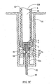
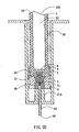
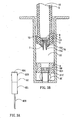
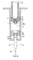
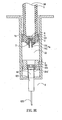
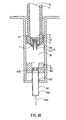
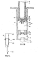
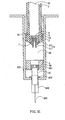
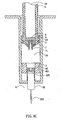
- FIGs. 2C to 2F illustrate the relative positions of the components of the safety syringe according to an embodiment of the invention at various stages.
- FIG. 2C illustrates the relative positions of the components of the safety syringe according to an embodiment of the invention during injection.
- the flexible seat 3 is fitted tightly against the inner wall of the outer syringe barrel 2, and the concave structure 32 of the flexible seat 3 is formed the sealed gap 35, thus the flexible seat 3 is fitted more tightly against the inner wall of the outer syringe barrel 2 by a compressive force from the medical solution so as to prevent the medical solution from overflowing during injection.
- the protrusion connection parts 71 are packed into the cave structure 64 of the needle seat 60 to make the anti-compressive structure 7 combine with the needle unit 6 and the width of two stretching sides of the neck parts 73 of the separating parts 74 reduce to be smaller than the inside diameter of the forward end 51 of the inner syringe barrel 5, thus the anti-compressive function of the anti-compressive structure 7 is released.
- the separating parts 74 of the anti-compressive structure 7 can be drawn inward by a reacting force applied by the needle unit 60 or the flexible seat 3, for example, the needle seat 60 can further comprise a pit in front of the cave structure 64, and a fore end of the individual separating parts 74 of the anti-compressive structure 7 can be drawn inward along a surface of the pit in front of the cave structure 64.
- the needle seat 60 of the needle unit 6 is held by the combined seat 214, the needle seat 60 can be kept a predetermined distance from the front-end opening 210 of the outer syringe barrel 2, and the forward end 51 of the inner syringe barrel 5 proceeds to move forward, then the flexible seat 3 is pushed away from the needle seat 60.
- the flexible sealing member 8 is slipped into the hollow body 50 of the inner syringe barrel 5 by the reaction force from the needle seat 60, as shown in FIG. 2E .
- the hollow body 50 of the inner syringe barrel 5 is in the low-pressure state. While the flexible sealing member 8 and the anti-compressive structure 7 are leaving away from the convergent part 53 and into a more spacious place, a radial compressive force from the inner wall of the hollow body 50 applied to the flexible sealing member 8 is reduced, thus the flexible sealing member 8, the anti-compressive structure 7, and the needle unit 6 combined with the anti-compressive structure 7 are retracted into the hollow body 50 of the inner syringe barrel 5 by the low-pressure attraction force, and the process of automatically retracting the needle unit 6 is done, as shown in FIG. 2F .
- the above-mentioned flexible components such as flexible seat 3, flexible sealing plunger 4, and the flexible sealing member 8, can be made of rubbers or other flexible materials.
- the anti-compressive structure 7 can be made of resin or plastic, but the present invention is not limited thereto.
- FIGs. 3A to 3E are cross-sectional views of a safety syringe with a replaceable needle body according to another embodiment of the present invention, wherein like reference numerals refer to like parts throughout the various figures unless otherwise specified.
- FIG. 3C is a cross-sectional view of a safety syringe with a replaceable needle body according to another embodiment of the present invention after assembly, in which the needle seat 60 of the needle unit 6 comprises a joint part 601 to be combined with the needle body 62.
- the joint part 601 of the needle seat 60 is exemplified by an inverse U-shaped sealing part, and the needle body 62 comprises a holding part 621 and a needle 622.
- the needle body 62 can be separated from the joint part 601 of the needle seat 60.
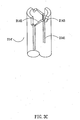
- FIG. 3A illustrates a needle body 62 with a pair of hook structures 623.
- the pair of hook structures 623 can be disposed on a sidewall of the holding part 621 of the needle body 62 oppositely, a concave part 624 with a funnel-like shape is on the top of the needle body 62, and the medical solution can be flowed to the needle 622 via the funnel-like shaped concave part 624.
- FIG. 3B illustrates a cross-sectional view of the safety syringe with a combined seat 214' having a track 2141, and the track 2141 is located in an inner wall surface of the combined seat 214'
- FIG. 3C shows an enlarged sectional view of the combined seat 214' with the track 2141.
- a track road 2142 is in the end of the track 2141 along the inner wall surface of the combined seat 214'
- a locking part 2143 such as a concave is in the end of the track road 2142.
- the track 2141, the track road 2142, and the locking part 2143 of the combined seat 214' can be designed corresponding to the hook structures 623 of the needle body 62.
- An operator can take the holding part 621 of the needle body 62 and put the hook structures 623 into the combined seat 214' along the track 2141, then the needle body 62 is passed through the through passage 212.
- the hook structures 623 of the needle body 62 are moved upward into the safety syringe along the track 2141, and turned along the track road 2142 into the locking part 2143, then a top portion of the needle body 62 is against the joint part 601 of the needle seat 60 tightly, thus the process of combining the needle unit 6 is done.
- the hook structures 623 of the needle body 62 can be separated from the locking part 2143 of the combined seat 214' by turning the opposite way, thus the needle body 62 is taken off from the joint part 601 of the needle seat 60.
- the track road 2142 can comprise a inclined surface.
- the joint part 601 of the needle seat 60 can comprise a thread so that the needle body 62 can be screwed to the needle seat 60. It is appreciated that the numbers and shapes of the hook structures 623 are not limited thereto, and the hook structures 623 can be disposed on the outside wall of the needle body 62 symmetrically or asymmetrically.
- the top portion of the needle body 62 can comprise a planar surface, the present invention is not limited thereto.
- FIGs. 4A to 4E are schematic views of a safety syringe with a replaceable needle body according to a further embodiment of the present invention, wherein like reference numerals refer to like parts throughout the various figures unless otherwise specified.
- the holding part 621 of the needle body 62 is disposed within a needle sheath 630, and the needle 622 is passed through a hole 631 in a front-end wall of the needle sheath 630 to be exposed outside of the needle sheath 630.
- a pair of hook structures 623' can be disposed on an outside wall of the needle sheath 630, and the needle body 62 can be separated from the needle sheath 630.
- FIG. 4C shows a vertical sectional view of the front end 21 of the outer syringe barrel 2.
- the operator can take the needle sheath 630 and put the needle body 62 into the safety syringe, the hook structures 623' of the needle sheath 630 are turned along the track road 2142' into the locking part 2143' to hold the needle sheath 630.
- a top portion of the needle sheath 630 is against a bottom of the needle seat 60 tightly, and the top portion 625 of the needle body 62 can be combined with the joint part 601 of the needle seat 60.
- the needle seat 60 is held by the needle sheath 630, and thus the needle seat 60 can be kept a predetermined distance from the front-end opening 210 of the outer syringe barrel 2.
- the needle sheath 630 can be taken off by turning the opposite way, thus the needle sheath 630 can be reused.
- FIGs. 5A to 5C illustrate a safety syringe with a replaceable needle body according to yet another embodiment of the present invention.
- the length of the needle sheath 630' above the hook structures 623' is shorter than that as illustrated in FIGs. 4A to 4E , and most of the top portion of the needle body 62 is exposed outside of the needle sheath 630'.
- the way to lock the hook structures 623' (with reference to FIG. 4C ), the way to combine the needle body 62 with the joint part 601 of the needle seat 60, and the way to retract the needle unit 6, are the same as those illustrated above.
- the sizes or the numbers of the hook structures 623' can be changed according to the needs and requirements, the present invention is not limited thereto.
- FIGs. 6A to 6C are schematic diagrams of a safety syringe with a replaceable needle body according to still yet another embodiment of the present invention, wherein like reference numerals refer to like parts throughout the various figures unless otherwise specified.
- the top portion 625 of the needle body 62 comprises a thread 626 and a funnel-like shaped concave part 624
- the bottom of the needle body 62 comprises a needle 622.
- a joint part 601 of the needle seat 60 comprises a thread that can be mated with the thread 626 in the top portion 625 of the needle body 62, such that the needle body 62 can be screwed to the joint part 601 of the needle seat 60.
- the needle body 62 is combined with the needle seat 60 to assemble a needle unit 6 by way of screwing, thus the needle unit 6 can be retracted into the hollow body 50 of the inner syringe barrel 5 along with the flexible sealing member 8, as shown in FIG. 6C .
- the safety syringes of the present invention may be used to prevent an operating staff from infections effectively.
- the safety syringes of the present invention may be more environment friendly because the needle unit may be retracted by a low pressure, not other components (such as spring).
- the needle body of the needle syringe according to the present invention may be replaced while the needle is damaged, thus the safety syringe is not necessary to be changed entirely.
- the safety syringes provided by the present invention may not only be economic but may also be environment friendly.
Landscapes
- Health & Medical Sciences (AREA)
- Engineering & Computer Science (AREA)
- Heart & Thoracic Surgery (AREA)
- Vascular Medicine (AREA)
- Anesthesiology (AREA)
- Biomedical Technology (AREA)
- Environmental & Geological Engineering (AREA)
- Hematology (AREA)
- Life Sciences & Earth Sciences (AREA)
- Animal Behavior & Ethology (AREA)
- General Health & Medical Sciences (AREA)
- Public Health (AREA)
- Veterinary Medicine (AREA)
- Infusion, Injection, And Reservoir Apparatuses (AREA)
Claims (10)
- Sicherheitsspritze, umfassend:einen äußeren Spritzenzylinder (2) mit einer vorderen Öffnung (210) und einer hinteren Öffnung (220);einen flexiblen Einsatz (3), der an der Innenwand des äußeren Spritzenzylinders (2) eingepasst ist;eine Nadeleinheit (6), die einen Nadelsitz (60) und einen Nadelkörper (62), der mit diesem Nadelsitz (60) verbunden ist, umfasst, wobei der Nadelsitz (60) in lösbarem Eingriff mit dem flexiblen Einsatz (3) ist;einen inneren Spritzenzylinder (5) mit einem vorderen Ende (51), einem hinteren Ende (52) und einem Hohlkörper (50) zwischen dem vorderen Ende (51) und dem hinteren Ende (52), wobei das vordere Ende (51) des inneren Spritzenzylinders (5) eine vordere Öffnung (510) umfasst, der Innendurchmesser der vorderen Öffnung (510) größer ist als der Außendurchmesser des Nadelsitzes (60), und der innere Spritzenzylinder (5) durch die hintere Öffnung (220) des äußeren Spritzenzylinders (2) in den äußeren Spritzenzylinder (2) eingeführt werden kann;ein flexibles Dichtungselement (8), das an der Innenwand des vorderen Endes (51) des inneren Spritzenzylinders (5) angebracht ist, damit der Hohlkörper (50) des inneren Spritzenzylinders (5) einen abgedichteten Raum bildet;dadurch gekennzeichnet, dass:eine Antidruckstruktur (7) mit dem flexiblen Dichtungselement (8) verbunden ist, um zu verhindern, dass das flexible Dichtungselement (8) während einer Injektion in den Hohlkörper (50) des inneren Spritzenzylinders (5) rutscht;wodurch, wenn der innere Spritzenzylinder (5) in Richtung der vorderen Öffnung (210) des äußeren Spritzenzylinders (2) bewegt wird, die Antidruckstruktur (7) mit der Nadeleinheit (6) verbunden wird, wobei das vordere Ende (51) des inneren Spritzenzylinders (5) gegen den flexiblen Einsatz (3) drückt, um die Kombination aus Nadeleinheit (6) und flexiblem Einsatz (3) aus dem gegenseitigen Eingriff zu lösen, wonach das flexible Dichtungselement (8) durch die von der Nadeleinheit (6) aufgebrachte Gegenkraft in den Hohlkörper (50) des inneren Spritzenzylinders (5) gedrückt wird.
- Sicherheitsspritze nach Anspruch 1, wobei sich der abgedichtete Raum im Hohlkörper (50) des inneren Spritzenzylinders (5) in einem Niederdruckzustand befindet.
- Sicherheitsspritze nach Anspruch 1 oder 2, wobei die Antidruckstruktur (7) Folgendes umfasst:ein Kopfteil (72), das in der Lage ist, sich mit dem flexiblen Dichtungselement (8) zu verbinden;ein Halsteil (73), das mit dem Kopfteil (72) verbunden ist, wobei das Halsteil (73) am vorderen Ende (51) des inneren Spritzenzylinders (5) einrastet, um zu verhindern, dass das flexible Dichtungselement (8) in den Hohlkörper (50) des inneren Spritzenzylinders (5) rutscht; undein Verbindungsteil (71), das mit dem Halsteil (73) verbunden ist, wobei das Verbindungsteil (71) in der Lage ist, sich mit dem Nadelsitz (60) der Nadeleinheit (6) zu verbinden.
- Sicherheitsspritze nach Anspruch 3, wobei die Antidruckstruktur (7) zumindest ein Trennteil (74) umfasst, das aus dem Halsteil (73) und dem Verbindungsteil (71) besteht.
- Sicherheitsspritze nach Anspruch 4, wobei der Nadelsitz (60) der Nadeleinheit (6) ein Kombinationsteil umfasst und wobei, wenn der innere Spritzenzylinder (5) in Richtung der vorderen Öffnung (210) des äußeren Spritzenzylinders (2) bewegt wird, das Trennteil (74) der Antidruckstruktur (7) nach innen gezogen wird und der Außenrand des Halsteils (73) der Antidruckstruktur (7) innerhalb der vorderen Öffnung (510) des inneren Spritzenzylinders (5) verkleinert wird, wobei das Verbindungsteil (71) des Trennteils (74) mit dem Kombinationsteil der Nadeleinheit (6) verbunden wird, sodass die Antidruckstruktur (7) mit der Nadeleinheit (6) in verbunden wird.
- Sicherheitsspritze nach Anspruch 1 oder 2, wobei der Nadelsitz (60) der Nadeleinheit (6) ein Einsetzteil (601) umfasst, das mit dem Nadelkörper (62) verbunden ist, und der Nadelkörper (62) von diesem Einsetzteil (601) des Nadelsitzes (60) abgetrennt werden kann.
- Sicherheitsspritze nach Anspruch 1 oder 2, weiters einen Verbindungssitz (214') umfassend, der angrenzend an das vordere Ende (21) des äußeren Spritzenzylinders (2) angeordnet ist, wobei der Verbindungssitz (214') einen Durchlass umfasst, der mit der vorderen Öffnung (210) des äußeren Spritzenzylinders (2) kommuniziert, wobei der Nadelsitz (60), der mit dem flexiblen Einsatz (3) verbunden ist, vom Verbindungssitz getragen wird, wodurch der Nadelsitz (60) in einem vorbestimmten Abstand von der vorderen Öffnung (210) des äußeren Spritzenzylinders (2) gehalten wird und der Nadelkörper (62) durch den Durchlass des Verbindungssitzes und die vordere Öffnung (210) des äußeren Spritzenzylinders (2) geführt wird.
- Sicherheitsspritze nach Anspruch 6, weiters einen Verbindungssitz umfassend, der angrenzend an das vordere Ende (21) des äußeren Spritzenzylinders (2) angeordnet ist, wobei der Verbindungssitz (214') einen Durchlass umfasst, der mit der vorderen Öffnung (210) des äußeren Spritzenzylinders (2) kommuniziert, wobei der Nadelsitz (60) mit dem flexiblen Einsatz (3) vom Verbindungssitz (214') getragen wird, wodurch der Nadelsitz (60) in einem vorbestimmten Abstand von der vorderen Öffnung (210) des äußeren Spritzenzylinders (2) gehalten wird und der Nadelkörper (62) durch den Durchlass des Verbindungssitzes (214') geführt und mit dem Einsetzteil (601) des Nadelsitzes (60) verbunden wird.
- Sicherheitsspritze nach Anspruch 8, wobei der Verbindungssitz (214') eine Innenwandfläche umfasst, sich eine Spur (2141) auf der Innenwandfläche des Verbindungssitzes (214') befindet, sich eine Spurbahn (2142) am Ende der Spur (2141) entlang der Innenwandfläche des Verbindungssitzes (214') befindet, und sich ein Verriegelungsteil (2143) am Ende der Spurbahn (2142) befindet.
- Sicherheitsspritze nach Anspruch 9, wobei der Nadelkörper 62 eine Einhakstruktur (623) umfasst, die mit der Spur (2141) übereinstimmt, wobei der Nadelkörper (62) durch den Durchlass (212) entlang der Spur (2141) geführt wird, und die Einhakstruktur (623) des Nadelkörpers (62) mithilfe des Verriegelungsteils (2143) entlang der Spurbahn (2142) verriegelt wird, sodass der Nadelkörper (62) mit dem Einsetzteil (601) des Nadelsitzes (60) verbunden ist.
Priority Applications (3)
| Application Number | Priority Date | Filing Date | Title |
|---|---|---|---|
| DE602006018465T DE602006018465D1 (de) | 2006-08-22 | 2006-08-22 | Sicherheitsspritze |
| AT06254393T ATE489126T1 (de) | 2006-08-22 | 2006-08-22 | Sicherheitsspritze |
| EP06254393A EP1900386B1 (de) | 2006-08-22 | 2006-08-22 | Sicherheitsspritze |
Applications Claiming Priority (1)
| Application Number | Priority Date | Filing Date | Title |
|---|---|---|---|
| EP06254393A EP1900386B1 (de) | 2006-08-22 | 2006-08-22 | Sicherheitsspritze |
Publications (2)
| Publication Number | Publication Date |
|---|---|
| EP1900386A1 EP1900386A1 (de) | 2008-03-19 |
| EP1900386B1 true EP1900386B1 (de) | 2010-11-24 |
Family
ID=37668180
Family Applications (1)
| Application Number | Title | Priority Date | Filing Date |
|---|---|---|---|
| EP06254393A Expired - Lifetime EP1900386B1 (de) | 2006-08-22 | 2006-08-22 | Sicherheitsspritze |
Country Status (3)
| Country | Link |
|---|---|
| EP (1) | EP1900386B1 (de) |
| AT (1) | ATE489126T1 (de) |
| DE (1) | DE602006018465D1 (de) |
Families Citing this family (1)
| Publication number | Priority date | Publication date | Assignee | Title |
|---|---|---|---|---|
| CN110876824A (zh) * | 2018-09-06 | 2020-03-13 | 广东海鸥医疗器械股份有限公司 | 一种注射器 |
Family Cites Families (2)
| Publication number | Priority date | Publication date | Assignee | Title |
|---|---|---|---|---|
| US7410478B2 (en) * | 2001-08-17 | 2008-08-12 | Chih Ming Wang | Safety syringe with needle retracting mechanism |
| EP1442763A1 (de) * | 2003-01-28 | 2004-08-04 | Chung-Yu Yang | Sicherheitsspritze mit durch Vakuum zurückziehbarer Nadel |
-
2006
- 2006-08-22 DE DE602006018465T patent/DE602006018465D1/de not_active Expired - Lifetime
- 2006-08-22 AT AT06254393T patent/ATE489126T1/de not_active IP Right Cessation
- 2006-08-22 EP EP06254393A patent/EP1900386B1/de not_active Expired - Lifetime
Also Published As
| Publication number | Publication date |
|---|---|
| ATE489126T1 (de) | 2010-12-15 |
| DE602006018465D1 (de) | 2011-01-05 |
| EP1900386A1 (de) | 2008-03-19 |
Similar Documents
| Publication | Publication Date | Title |
|---|---|---|
| US20070078402A1 (en) | Safety Syringe | |
| US7410478B2 (en) | Safety syringe with needle retracting mechanism | |
| CN101085383A (zh) | 与前端附件联合使用的具有内凹前端的注射器 | |
| US20050203458A1 (en) | Safe retractable type syringe | |
| US7955300B2 (en) | Disposable safety syringe with retractable needle | |
| US11065394B2 (en) | Syringe with retractable needle | |
| ES2317532T3 (es) | Un adaptador de placa de apoyo para piston de jeringa. | |
| JP2005312895A (ja) | 注射器 | |
| CN106955399A (zh) | 安全注射器 | |
| US20070078408A1 (en) | Disposable safety syringe for dispensing anesthetic | |
| US20050049554A1 (en) | Breakable syringe | |
| US6436076B1 (en) | Needle holder positioning structure for a safety syringe | |
| EP1547634A1 (de) | Sicherheitsspritze | |
| JP5372350B2 (ja) | 注射器及びプランジャロッド | |
| EP1900386A1 (de) | Sicherheitsspritze | |
| US8034025B1 (en) | Disposable safety syringe | |
| EP2446913A1 (de) | Einziehbare struktur einer sicherheitsspritze | |
| WO2009097743A1 (zh) | 安全注射器芯杆锁定装置 | |
| US7927301B2 (en) | Safety syringe | |
| US20070078405A1 (en) | Safety syringe | |
| US12539256B2 (en) | Connector | |
| AU2003101038A4 (en) | Safety Fluid Injecting/Sampling Apparatus | |
| EP1369138A1 (de) | Befestigungsgefüge eines Nadelhalters für eine Sicherheitsspritze | |
| US20080161760A1 (en) | Medical Device Containing a Vacuum Chamber | |
| US7074207B2 (en) | Safety syringe |
Legal Events
| Date | Code | Title | Description |
|---|---|---|---|
| PUAI | Public reference made under article 153(3) epc to a published international application that has entered the european phase |
Free format text: ORIGINAL CODE: 0009012 |
|
| 17P | Request for examination filed |
Effective date: 20060911 |
|
| AK | Designated contracting states |
Kind code of ref document: A1 Designated state(s): AT BE BG CH CY CZ DE DK EE ES FI FR GB GR HU IE IS IT LI LT LU LV MC NL PL PT RO SE SI SK TR |
|
| AX | Request for extension of the european patent |
Extension state: AL BA HR MK YU |
|
| AKX | Designation fees paid |
Designated state(s): AT BE BG CH CY CZ DE DK EE ES FI FR GB GR HU IE IS IT LI LT LU LV MC NL PL PT RO SE SI SK TR |
|
| GRAP | Despatch of communication of intention to grant a patent |
Free format text: ORIGINAL CODE: EPIDOSNIGR1 |
|
| GRAS | Grant fee paid |
Free format text: ORIGINAL CODE: EPIDOSNIGR3 |
|
| GRAA | (expected) grant |
Free format text: ORIGINAL CODE: 0009210 |
|
| AK | Designated contracting states |
Kind code of ref document: B1 Designated state(s): AT BE BG CH CY CZ DE DK EE ES FI FR GB GR HU IE IS IT LI LT LU LV MC NL PL PT RO SE SI SK TR |
|
| REG | Reference to a national code |
Ref country code: GB Ref legal event code: FG4D |
|
| REG | Reference to a national code |
Ref country code: CH Ref legal event code: EP |
|
| REG | Reference to a national code |
Ref country code: IE Ref legal event code: FG4D |
|
| REF | Corresponds to: |
Ref document number: 602006018465 Country of ref document: DE Date of ref document: 20110105 Kind code of ref document: P |
|
| REG | Reference to a national code |
Ref country code: NL Ref legal event code: T3 |
|
| LTIE | Lt: invalidation of european patent or patent extension |
Effective date: 20101124 |
|
| PG25 | Lapsed in a contracting state [announced via postgrant information from national office to epo] |
Ref country code: LT Free format text: LAPSE BECAUSE OF FAILURE TO SUBMIT A TRANSLATION OF THE DESCRIPTION OR TO PAY THE FEE WITHIN THE PRESCRIBED TIME-LIMIT Effective date: 20101124 |
|
| PG25 | Lapsed in a contracting state [announced via postgrant information from national office to epo] |
Ref country code: LV Free format text: LAPSE BECAUSE OF FAILURE TO SUBMIT A TRANSLATION OF THE DESCRIPTION OR TO PAY THE FEE WITHIN THE PRESCRIBED TIME-LIMIT Effective date: 20101124 Ref country code: IS Free format text: LAPSE BECAUSE OF FAILURE TO SUBMIT A TRANSLATION OF THE DESCRIPTION OR TO PAY THE FEE WITHIN THE PRESCRIBED TIME-LIMIT Effective date: 20110324 Ref country code: FI Free format text: LAPSE BECAUSE OF FAILURE TO SUBMIT A TRANSLATION OF THE DESCRIPTION OR TO PAY THE FEE WITHIN THE PRESCRIBED TIME-LIMIT Effective date: 20101124 Ref country code: SE Free format text: LAPSE BECAUSE OF FAILURE TO SUBMIT A TRANSLATION OF THE DESCRIPTION OR TO PAY THE FEE WITHIN THE PRESCRIBED TIME-LIMIT Effective date: 20101124 Ref country code: CY Free format text: LAPSE BECAUSE OF FAILURE TO SUBMIT A TRANSLATION OF THE DESCRIPTION OR TO PAY THE FEE WITHIN THE PRESCRIBED TIME-LIMIT Effective date: 20101124 Ref country code: AT Free format text: LAPSE BECAUSE OF FAILURE TO SUBMIT A TRANSLATION OF THE DESCRIPTION OR TO PAY THE FEE WITHIN THE PRESCRIBED TIME-LIMIT Effective date: 20101124 Ref country code: PT Free format text: LAPSE BECAUSE OF FAILURE TO SUBMIT A TRANSLATION OF THE DESCRIPTION OR TO PAY THE FEE WITHIN THE PRESCRIBED TIME-LIMIT Effective date: 20110324 Ref country code: BG Free format text: LAPSE BECAUSE OF FAILURE TO SUBMIT A TRANSLATION OF THE DESCRIPTION OR TO PAY THE FEE WITHIN THE PRESCRIBED TIME-LIMIT Effective date: 20110224 Ref country code: SI Free format text: LAPSE BECAUSE OF FAILURE TO SUBMIT A TRANSLATION OF THE DESCRIPTION OR TO PAY THE FEE WITHIN THE PRESCRIBED TIME-LIMIT Effective date: 20101124 |
|
| PG25 | Lapsed in a contracting state [announced via postgrant information from national office to epo] |
Ref country code: GR Free format text: LAPSE BECAUSE OF FAILURE TO SUBMIT A TRANSLATION OF THE DESCRIPTION OR TO PAY THE FEE WITHIN THE PRESCRIBED TIME-LIMIT Effective date: 20110225 |
|
| PG25 | Lapsed in a contracting state [announced via postgrant information from national office to epo] |
Ref country code: ES Free format text: LAPSE BECAUSE OF FAILURE TO SUBMIT A TRANSLATION OF THE DESCRIPTION OR TO PAY THE FEE WITHIN THE PRESCRIBED TIME-LIMIT Effective date: 20110307 Ref country code: BE Free format text: LAPSE BECAUSE OF FAILURE TO SUBMIT A TRANSLATION OF THE DESCRIPTION OR TO PAY THE FEE WITHIN THE PRESCRIBED TIME-LIMIT Effective date: 20101124 Ref country code: CZ Free format text: LAPSE BECAUSE OF FAILURE TO SUBMIT A TRANSLATION OF THE DESCRIPTION OR TO PAY THE FEE WITHIN THE PRESCRIBED TIME-LIMIT Effective date: 20101124 Ref country code: EE Free format text: LAPSE BECAUSE OF FAILURE TO SUBMIT A TRANSLATION OF THE DESCRIPTION OR TO PAY THE FEE WITHIN THE PRESCRIBED TIME-LIMIT Effective date: 20101124 |
|
| PG25 | Lapsed in a contracting state [announced via postgrant information from national office to epo] |
Ref country code: DK Free format text: LAPSE BECAUSE OF FAILURE TO SUBMIT A TRANSLATION OF THE DESCRIPTION OR TO PAY THE FEE WITHIN THE PRESCRIBED TIME-LIMIT Effective date: 20101124 Ref country code: PL Free format text: LAPSE BECAUSE OF FAILURE TO SUBMIT A TRANSLATION OF THE DESCRIPTION OR TO PAY THE FEE WITHIN THE PRESCRIBED TIME-LIMIT Effective date: 20101124 Ref country code: SK Free format text: LAPSE BECAUSE OF FAILURE TO SUBMIT A TRANSLATION OF THE DESCRIPTION OR TO PAY THE FEE WITHIN THE PRESCRIBED TIME-LIMIT Effective date: 20101124 Ref country code: RO Free format text: LAPSE BECAUSE OF FAILURE TO SUBMIT A TRANSLATION OF THE DESCRIPTION OR TO PAY THE FEE WITHIN THE PRESCRIBED TIME-LIMIT Effective date: 20101124 |
|
| PLBE | No opposition filed within time limit |
Free format text: ORIGINAL CODE: 0009261 |
|
| STAA | Information on the status of an ep patent application or granted ep patent |
Free format text: STATUS: NO OPPOSITION FILED WITHIN TIME LIMIT |
|
| 26N | No opposition filed |
Effective date: 20110825 |
|
| REG | Reference to a national code |
Ref country code: DE Ref legal event code: R097 Ref document number: 602006018465 Country of ref document: DE Effective date: 20110825 |
|
| PG25 | Lapsed in a contracting state [announced via postgrant information from national office to epo] |
Ref country code: IT Free format text: LAPSE BECAUSE OF FAILURE TO SUBMIT A TRANSLATION OF THE DESCRIPTION OR TO PAY THE FEE WITHIN THE PRESCRIBED TIME-LIMIT Effective date: 20101124 |
|
| PG25 | Lapsed in a contracting state [announced via postgrant information from national office to epo] |
Ref country code: MC Free format text: LAPSE BECAUSE OF NON-PAYMENT OF DUE FEES Effective date: 20110831 |
|
| REG | Reference to a national code |
Ref country code: CH Ref legal event code: PL |
|
| PG25 | Lapsed in a contracting state [announced via postgrant information from national office to epo] |
Ref country code: CH Free format text: LAPSE BECAUSE OF NON-PAYMENT OF DUE FEES Effective date: 20110831 Ref country code: LI Free format text: LAPSE BECAUSE OF NON-PAYMENT OF DUE FEES Effective date: 20110831 |
|
| REG | Reference to a national code |
Ref country code: IE Ref legal event code: MM4A |
|
| PG25 | Lapsed in a contracting state [announced via postgrant information from national office to epo] |
Ref country code: IE Free format text: LAPSE BECAUSE OF NON-PAYMENT OF DUE FEES Effective date: 20110822 |
|
| PG25 | Lapsed in a contracting state [announced via postgrant information from national office to epo] |
Ref country code: LU Free format text: LAPSE BECAUSE OF NON-PAYMENT OF DUE FEES Effective date: 20110822 |
|
| PG25 | Lapsed in a contracting state [announced via postgrant information from national office to epo] |
Ref country code: TR Free format text: LAPSE BECAUSE OF FAILURE TO SUBMIT A TRANSLATION OF THE DESCRIPTION OR TO PAY THE FEE WITHIN THE PRESCRIBED TIME-LIMIT Effective date: 20101124 |
|
| PG25 | Lapsed in a contracting state [announced via postgrant information from national office to epo] |
Ref country code: HU Free format text: LAPSE BECAUSE OF FAILURE TO SUBMIT A TRANSLATION OF THE DESCRIPTION OR TO PAY THE FEE WITHIN THE PRESCRIBED TIME-LIMIT Effective date: 20101124 |
|
| PGFP | Annual fee paid to national office [announced via postgrant information from national office to epo] |
Ref country code: DE Payment date: 20130827 Year of fee payment: 8 |
|
| PGFP | Annual fee paid to national office [announced via postgrant information from national office to epo] |
Ref country code: GB Payment date: 20130821 Year of fee payment: 8 Ref country code: FR Payment date: 20130827 Year of fee payment: 8 |
|
| PGFP | Annual fee paid to national office [announced via postgrant information from national office to epo] |
Ref country code: NL Payment date: 20130827 Year of fee payment: 8 |
|
| REG | Reference to a national code |
Ref country code: DE Ref legal event code: R119 Ref document number: 602006018465 Country of ref document: DE |
|
| REG | Reference to a national code |
Ref country code: NL Ref legal event code: V1 Effective date: 20150301 |
|
| GBPC | Gb: european patent ceased through non-payment of renewal fee |
Effective date: 20140822 |
|
| PG25 | Lapsed in a contracting state [announced via postgrant information from national office to epo] |
Ref country code: NL Free format text: LAPSE BECAUSE OF NON-PAYMENT OF DUE FEES Effective date: 20150301 |
|
| REG | Reference to a national code |
Ref country code: DE Ref legal event code: R119 Ref document number: 602006018465 Country of ref document: DE Effective date: 20150303 |
|
| REG | Reference to a national code |
Ref country code: FR Ref legal event code: ST Effective date: 20150430 |
|
| PG25 | Lapsed in a contracting state [announced via postgrant information from national office to epo] |
Ref country code: DE Free format text: LAPSE BECAUSE OF NON-PAYMENT OF DUE FEES Effective date: 20150303 Ref country code: GB Free format text: LAPSE BECAUSE OF NON-PAYMENT OF DUE FEES Effective date: 20140822 |
|
| PG25 | Lapsed in a contracting state [announced via postgrant information from national office to epo] |
Ref country code: FR Free format text: LAPSE BECAUSE OF NON-PAYMENT OF DUE FEES Effective date: 20140901 |