EP1900423A1 - Belüftungsanlage - Google Patents
Belüftungsanlage Download PDFInfo
- Publication number
- EP1900423A1 EP1900423A1 EP06019163A EP06019163A EP1900423A1 EP 1900423 A1 EP1900423 A1 EP 1900423A1 EP 06019163 A EP06019163 A EP 06019163A EP 06019163 A EP06019163 A EP 06019163A EP 1900423 A1 EP1900423 A1 EP 1900423A1
- Authority
- EP
- European Patent Office
- Prior art keywords
- aeration
- nozzle assembly
- equipment
- apparatuses
- aeration equipment
- Prior art date
- Legal status (The legal status is an assumption and is not a legal conclusion. Google has not performed a legal analysis and makes no representation as to the accuracy of the status listed.)
- Withdrawn
Links
- 238000005273 aeration Methods 0.000 title claims abstract description 254
- XLYOFNOQVPJJNP-UHFFFAOYSA-N water Substances O XLYOFNOQVPJJNP-UHFFFAOYSA-N 0.000 claims description 52
- 238000005276 aerator Methods 0.000 claims description 17
- 230000000712 assembly Effects 0.000 claims description 15
- 238000000429 assembly Methods 0.000 claims description 15
- 238000005034 decoration Methods 0.000 claims description 11
- 125000004122 cyclic group Chemical group 0.000 claims description 10
- 238000001914 filtration Methods 0.000 claims 1
- 238000000034 method Methods 0.000 abstract description 7
- 239000007921 spray Substances 0.000 description 5
- 239000007789 gas Substances 0.000 description 4
- 238000005507 spraying Methods 0.000 description 4
- 244000005700 microbiome Species 0.000 description 3
- 239000010865 sewage Substances 0.000 description 3
- QVGXLLKOCUKJST-UHFFFAOYSA-N atomic oxygen Chemical compound [O] QVGXLLKOCUKJST-UHFFFAOYSA-N 0.000 description 2
- 238000009792 diffusion process Methods 0.000 description 2
- 239000000203 mixture Substances 0.000 description 2
- 239000001301 oxygen Substances 0.000 description 2
- 229910052760 oxygen Inorganic materials 0.000 description 2
- 231100000167 toxic agent Toxicity 0.000 description 2
- 239000003440 toxic substance Substances 0.000 description 2
- 241000251468 Actinopterygii Species 0.000 description 1
- QGZKDVFQNNGYKY-UHFFFAOYSA-N Ammonia Chemical compound N QGZKDVFQNNGYKY-UHFFFAOYSA-N 0.000 description 1
- JVMRPSJZNHXORP-UHFFFAOYSA-N ON=O.ON=O.ON=O.N Chemical compound ON=O.ON=O.ON=O.N JVMRPSJZNHXORP-UHFFFAOYSA-N 0.000 description 1
- MMDJDBSEMBIJBB-UHFFFAOYSA-N [O-][N+]([O-])=O.[O-][N+]([O-])=O.[O-][N+]([O-])=O.[NH6+3] Chemical compound [O-][N+]([O-])=O.[O-][N+]([O-])=O.[O-][N+]([O-])=O.[NH6+3] MMDJDBSEMBIJBB-UHFFFAOYSA-N 0.000 description 1
- 238000003889 chemical engineering Methods 0.000 description 1
- 230000007613 environmental effect Effects 0.000 description 1
- 238000004519 manufacturing process Methods 0.000 description 1
- 230000002093 peripheral effect Effects 0.000 description 1
- 238000005086 pumping Methods 0.000 description 1
- 230000029058 respiratory gaseous exchange Effects 0.000 description 1
- 230000000087 stabilizing effect Effects 0.000 description 1
- 238000003756 stirring Methods 0.000 description 1
- 239000000126 substance Substances 0.000 description 1
- 239000002699 waste material Substances 0.000 description 1
- 239000003643 water by type Substances 0.000 description 1
Images




Classifications
-
- A—HUMAN NECESSITIES
- A01—AGRICULTURE; FORESTRY; ANIMAL HUSBANDRY; HUNTING; TRAPPING; FISHING
- A01K—ANIMAL HUSBANDRY; AVICULTURE; APICULTURE; PISCICULTURE; FISHING; REARING OR BREEDING ANIMALS, NOT OTHERWISE PROVIDED FOR; NEW BREEDS OF ANIMALS
- A01K63/00—Receptacles for live fish, e.g. aquaria; Terraria
- A01K63/04—Arrangements for treating water specially adapted to receptacles for live fish
- A01K63/042—Introducing gases into the water, e.g. aerators, air pumps
-
- B—PERFORMING OPERATIONS; TRANSPORTING
- B01—PHYSICAL OR CHEMICAL PROCESSES OR APPARATUS IN GENERAL
- B01F—MIXING, e.g. DISSOLVING, EMULSIFYING OR DISPERSING
- B01F23/00—Mixing according to the phases to be mixed, e.g. dispersing or emulsifying
- B01F23/20—Mixing gases with liquids
- B01F23/23—Mixing gases with liquids by introducing gases into liquid media, e.g. for producing aerated liquids
- B01F23/234—Surface aerating
-
- B—PERFORMING OPERATIONS; TRANSPORTING
- B01—PHYSICAL OR CHEMICAL PROCESSES OR APPARATUS IN GENERAL
- B01F—MIXING, e.g. DISSOLVING, EMULSIFYING OR DISPERSING
- B01F33/00—Other mixers; Mixing plants; Combinations of mixers
- B01F33/50—Movable or transportable mixing devices or plants
- B01F33/503—Floating mixing devices
-
- B—PERFORMING OPERATIONS; TRANSPORTING
- B01—PHYSICAL OR CHEMICAL PROCESSES OR APPARATUS IN GENERAL
- B01F—MIXING, e.g. DISSOLVING, EMULSIFYING OR DISPERSING
- B01F25/00—Flow mixers; Mixers for falling materials, e.g. solid particles
- B01F25/20—Jet mixers, i.e. mixers using high-speed fluid streams
-
- B—PERFORMING OPERATIONS; TRANSPORTING
- B01—PHYSICAL OR CHEMICAL PROCESSES OR APPARATUS IN GENERAL
- B01F—MIXING, e.g. DISSOLVING, EMULSIFYING OR DISPERSING
- B01F35/00—Accessories for mixers; Auxiliary operations or auxiliary devices; Parts or details of general application
- B01F35/30—Driving arrangements; Transmissions; Couplings; Brakes
- B01F35/32—Driving arrangements
- B01F35/32005—Type of drive
- B01F35/32015—Flow driven
Definitions
- the present invention generally relates to the aeration equipment, and more particularly, the methods of the movement and controls of an aeration equipment, which moves by employing the reacting forces generated while aerating, and controlling the direction of movement with a control device to determine the resultant direction.
- D.O. Dissolved Oxygen
- the major method of maintaining the concentration of the D.O. (Dissolved Oxygen) in the aquafarms and fish eries is often employed by the aeration equipment, which maintains adequate respiration conditions for aquatic products, water life, and microorganisms. The stability of the water quality and the ecological balance are maintained as well.
- D.O. Dissolved Oxygen
- microorganisms have to absorb the dissolved oxygen for digesting the waste organisms in accordance with the process of the nitrification, converting the high toxicant ammonia gas Into the weak toxicant nitrite nitrogen ( NO 2 ) or nitrate nitrogen ( NO 3 ) .
- a waterwheel spins and stirs up the nearby water with its motor vanes for the extension of the contacting area and the contacting time between the water and the air, resulting in an increase of the concentration of the D.O. and aeration.
- An object of the present invention is to provide an aeration equipment having a plurality of pumps of an aeration apparatus that has higher aeration efficiency and effectiveness than the conventional aeration equipment, such as a waterwheel.
- An additional object of the present invention is the provision of an aeration equipment having a plurality of aeration apparatuses, arranged in an asymmetric disposition, with a plurality of nozzle assemblies that generate a thrust to move the aeration equipment.
- Another object of the present invention Is to provide an aeration equipment having the aforesaid thrust that provides the aeration equipment with the mobility and a larger aerating range than the fixed aeration equipment, such as a waterwheel.
- a further object of the present invention is the provision of an aeration equipment having a plurality of aeration apparatuses where the direction of movement of the aeration equipment can be determined by employing a control device to switch on/off the plurality of aeration apparatuses having an asymmetric disposition by turns.
- Yet another object of the present invention is to provide an aeration equipment having a plurality of jet aerators as an aerating resource that the jet aerators introducing the air from the water surface and draining the ambient water for mixing them both, and then, jetting this air-mixed water into the water as an aeration and generating the reacting forces as a thrust in the meantime.
- a further additional object of the present Invention is the provision of an aeration equipment further comprising a decoration apparatus that increases the function of the aeration equipment while aerating.
- Yet a further object of the present invention is to provide an aeration that increases the concentration of the D.O. and the water quality.
- An object of the present invention is the provision of an aeration equipment having the feature of mobility that reduces a number of the aeration equipments in one water area, successfully minimizing the cost thereof.
- An additional objection of the present Invention is to provide an aeration equipment that can be broadly employed in many kinds of water, such as a river, an aquatic production farm, a fishery, a pond, a pool, or a water resource area.
- One embodiment of the present invention provides an aeration equipment comprising a plurality of aeration apparatuses, a floatable apparatus and a control device.
- the plurality of aeration apparatuses are mounted on the floatable apparatus.
- Each aeration apparatus has a plurality of pumps for pumping the water and at least a nozzle assembly, comprising at least one nozzle, for aerating and jetting out the water.
- the reacting forces are generated from the nozzle assemblies of the plurality of aeration apparatuses while jetting out and aerating the water. Owing to the resultant of the reacting forces, the thrust, generated by the nozzle assemblies, the aeration equipment is able to move in a direction opposite the nozzle assembly.
- a control device is used to control and switch the plurality of aeration apparatuses arranged in a desirable order on the floatable apparatus.
- the resultant results from the reacting force of each nozzle assembly of each aeration apparatus. Therefore, the direction of movement of the aeration equipment is determined by switching one or more selected aeration apparatuses with the control device. This mobility of the aeration equipment allows an enlarged, more effective aerating area.
- the aeration equipment has a plurality of aeration apparatuses, which are the plurality of jet aerators, often used for sewage treatment In environmental engineering or chemical engineering. These jet aerators pump water and air from ambient water surface, mix them together, and then spray them out into the water. Thus, the aeration is performed and the reacting forces are generated at the same time.
- the control device is used to make the aeration equipment moving in the selected direction by employing the resultant of the reacting forces generated from the aeration apparatuses so that the aerating range can be greatly enlarged.
- the aforementioned aeration apparatus will be referred to hereinafter as a jet aerator or an aeration apparatus with at least one nozzle assembly.
- an aeration equipment comprises a floatable apparatus, a control device, and two aeration apparatuses, mounted on the floatable apparatus. Therefore, two different magnitudes of the reacting forces are generated from two aeration apparatuses, respectively, in which the first aeration apparatus generates a greater reacting force than the second aeration apparatus. Consequently, the direction of the aeration equipment is the same as the resultant of the reacting forces, generated from the first and the second aeration apparatuses.
- the aforementioned the aeration apparatus will be referred to hereinafter as a jet aerator or an aeration apparatus with at least one nozzle assembly.
- the direction of movement of the aforesaid aeration equipment is determined by the direction of the resultant of the reacting forces and the aeration equipment moving in the opposite direction of the resultant of the reacting forces. It is readily known that the direction of movement of the aforesaid aeration equipment is controlled by switching on/off the first aeration apparatus while the second aeration apparatus is always switched on. Hence, the aforesaid aeration equipment moves against the direction of the resultant of the reacting forces where the first and the second aeration apparatuses generate the resultant of the reacting forces.
- the aeration equipment is able to move back and forth when the first aeration apparatus is juxtaposed and aligned with the second aeration apparatus.
- the included angle of the reacting forces of two aeration apparatuses reaches 180 degrees.
- an aeration equipment comprises a floatable apparatus, a control device, and a plurality of aeration apparatuses arranged divisibly in a cyclic disposition and mounted on the floatable apparatus.
- Each aeration apparatus has at least a nozzle assembly, where the outlet of the nozzle assembly is arranged to face the exterior of the cyclic disposition.
- the mobility of the aeration equipment results from the control of switching each aeration apparatus by turns.
- the aforementioned aeration apparatus will be referred to hereinafter as an jet aerator, a spraying apparatus, or an aeration apparatus with the nozzle assembly.
- an aeration equipment comprising a floatable apparatus, a control device, and a plurality of aeration apparatuses arranged in an alignment and mounted on the floatable apparatus.
- the final resultant of the reacting forces can be only determined by these two aeration apparatuses, installed in the ends of the alignment and when the spraying apparatuses, spraying the air-mixed water and generating neglected minor reacting forces, are arranged amid those two aeration apparatuses.
- an aeration equipment further comprising a floatable apparatus, a control device, a plurality of aeration apparatuses and a decoration apparatus mounted on the floatable apparatus.
- the decoration apparatus has nothing to do with the aerating and has no influence on the function of the plurality of aeration apparatuses.
- the aforementioned decoration apparatus will be referred to hereinafter as a deco art, an advertisement, or a display view model.
- FIG. 1 and FIG. 2 illustrate the side view and the top view respectively of an aeration equipment 100 of the preferred embodiment of the present invention, where the aeration equipment 100 has a plurality of aeration apparatuses.
- the aforementioned plurality of aeration apparatuses will be referred to hereinafter as two aeration apparatuses.
- the aeration equipment 100 of a preferred embodiment of the present invention comprises a first aeration apparatus 110, a second aeration apparatus 120, a floatable apparatus 160, and a control device 170.
- the first aeration apparatus 110 and the second aeration apparatus 120 are both mounted on the floatable apparatus 160.
- the floatable apparatus 160 is able to float on the water.
- the control device 170 is used to shift the operating statuses of the first aeration apparatus 110 and the second aeration apparatus 120 by switching on/off.
- the first aeration apparatus 110 has a first pump 111 with one water inlet and one water outlet to pump the water.
- the first pump 111 has a first filter 112 Installed in the water Inlet and a first nozzle assembly 113 Installed In the water outlet
- Each of the first nozzle assembly 113 has a first elevation angle 1131 ranging from 15 degrees to 50 degrees.
- the first nozzle assembly 113 can be replaced by a plurality of the first nozzle assemblies 113 arranged in a radial manner or the like.
- the second aeration apparatus 120 has a second pump 121 with another water inlet and another water outlet to pump the water.
- the second pump 121 has a second filter 122 installed in the water inlet and a second nozzle assembly 123 installed in the water outlet.
- Each of the second nozzle assembly 123 has a second elevation angle 1231 ranging from 16 degrees to 50 degrees.
- the second nozzle assembly 123 can be replaced by a plurality of the first nozzle assemblies 123 arranged in a radial manner or the like.
- the aforesaid aeration equipment 100 employs the first pump 111 of the first aeration apparatus 110 and the second pump 121 of the second aeration apparatus 120 to introduce the water and then spray water out from first nozzle assembly 113 of the first pump 111 and the second nozzle assembly 123 of the second pump 121. Since the orientation of the nozzle assembly 113 is opposite that of the nozzle assembly 123, the first aeration apparatus 110 and the second aeration apparatus 120 do not start at the same time.
- the first pump 111 pumps in the water and then sprays the water out from the nozzle assembly 113 for aeration. Meanwhile, thrust is generated by the reacting forces by the water spraying out. The thrust enables the aeration equipment 100 to move in the first direction.
- switching on the second aeration apparatus 120 and switching off the first aeration apparatus 110 makes the second pump121 pump the water and then spray the water out from the nozzle assembly 123 for aeration.
- the thrust is generated by the reacting forces while the water sprays out.
- the thrust enables the aeration equipment 100 to move in the second direction. Therefore, the aeration equipment 100 effectively increases the performance and the range of aeration from this mobility.
- the power magnitude of the first pump and the second pump both are not limited; they can be the same or not.
- the arrangement of the nozzle assembly 113 of the first aeration apparatus 110 and the nozzle assembly 123 of the second aeration apparatus 120 may be symmetric or asymmetric.
- the first aeration apparatus 110 is arranged on the opposite side of the second aeration apparatus 120 on the floatable apparatus 160, so the nozzle assembly 113 of the first aeration apparatus 110 naturally faces the opposite direction of the nozzle assembly 123 of the second aeration apparatus 120.
- the control of the first pump 111 and the second pump 121 both are employed by the switch In order to control the water ejection periodically.
- the first nozzle assembly 113 is switched on and the second nozzle assembly 123 is switched off at the same time.
- the thrust is generated from the reacting forces of the first nozzle assembly 113 and pushes the aeration equipment 100 to move automatically in a direction opposite of the first nozzle assembly 113.
- the second nozzle assembly 123 is switched off and the first nozzle assembly 113 is switched off in the mean time, thrust is generated from the reacting forces of the second nozzle assembly 123 and pushes the aeration equipment 100 to move automatically in a direction opposite of the second nozzle assembly 123.
- the direction of movement of the aeration equipment 100 may be changed by employing the difference of the horizontal reacting forces which are generated by the first aeration apparatus 110 and the second aeration apparatus 120.
- One method to generate different horizontal reacting forces is to adopt different powers of the pumps arranged on the first aeration apparatus 110 and the second aeration apparatus 120 individually.
- Another method to generate different horizontal reacting forces is to design a new nozzle assembly arranged on the first aeration apparatus 110 and the second aeration apparatus 120 individually. Examples are a nozzle assembly with different spout calibers, an asymmetric arrangement of the nozzle assemblies, or furthermore, different numbers and elevation angles of the nozzle assemblies.
- the power of the first pump 111 is smaller than the power of the second pump 121 while using the same size nozzle assemblies on the aeration equipment 100. Therefore, the jetting water flow rate is in direct ratio with the magnitude of the power of the pump.
- the thrust which is generated by the water ejection of the nozzle assemblies, is also in direct ratio with the power magnitude of the pump.
- the thrust of the first pump 111 is also smaller than the thrust of the second pump 121
- the first pump 111 is switched into an "always on” mode, and the second pump 121 is switched intermittently in an "on/off" mode controlled by a control device (not shown in figures), and this enables the aeration equipment 100 to move In the first direction where the smaller thrust is generated.
- the control device switches off the larger power pump, the second pump 121. So the aeration equipment 100 Is able turn its direction of movement to the opposite direction of the first direction.
- the aeration equipment 100 thus has the ability to move back and forth.
- the power of the first pump 111 is the same as the power of the second pump 121.
- the nozzle assembly having bigger angle of elevation produces smaller thrust than the nozzle assembly having smaller angle of elevation.
- the control device only controls the switch of the aeration apparatus with smaller angle of elevation of the nozzle assembly, which can produce bigger thrust, enabling the aeration equipment 100 to move freely. Therefore, the purpose of increasing the range of aeration and the performance are both accomplished.
- FIG. 3 shows the aeration equipment 100 of the present invention equipped with three aeration apparatuses, which are a first aeration apparatus 110, a second aeration apparatus 120, and a third aeration apparatus 130, and they are arranged In alignment
- the first aeration apparatus 110 and the second aeration apparatus 120 are respectively arranged on two sides of the floatable apparatus 160 correspondingly.
- the first nozzle assembly 113 and the second nozzle assembly 123 are individually arranged to face the opposite direction with one another correspondingly.
- the third aeration apparatus 130 can be additionally mounted on the floatable apparatus 160.
- the resultant of the reacting forces is zero when the arrangement of the nozzle assembly of the third aeration apparatus 130 is arranged in cyclic disposition around a periphery thereof.
- the first aeration apparatus 110 and the second aeration apparatus 120 are controlled in the manner described before whether the arrangement of the first nozzle assembly 113 and the second nozzle assembly123 are placed correspondingly or not
- the performance of the aeration equipment 100 can be increased with the third aeration apparatus 130.
- these three aeration apparatuses can be also arranged in a cyclic disposition, and the nozzle assemblies of these three aeration apparatuses face radically outward.
- FIG. 4 illustrates another embodiment of the aeration equipment 100 with four aeration apparatuses of the present invention.
- the aeration equipment 100 can move in the opposite direction of aeration apparatus, which is switched on while the others are switched off.
- the aerating equipment 100 can move automatically by switching off any one apparatus of these four apparatuses and switching on the others; or turning off two apparatuses, which adjoin each other.
- the performance and the range of the aeration equipment 100 can be increased effectively with the mobility while the movement of the aeration equipment 100 can be controlled by switching these aeration apparatuses with orders.
- FIG. 5 illustrates the embodiment of the multiple aeration apparatuses of the aeration equipment 100 of the present invention.
- the aeration equipment 100 further comprises a first aeration apparatus 110, a second aeration apparatus 120, a third aeration apparatus 130, a fourth aeration apparatus 140, a fifth aeration apparatus 150, a floatable apparatus 160, and a control device 170 (not shown in FIG. 5).
- These peripheral aeration apparatuses are arranged correspondingly and evenly with each other in a cyclic disposition, and moreover, an aeration apparatus 150 is also installed in the center of the floatable apparatus 160.
- a nozzle assembly of the central aeration apparatus 150, arranged in the center of the floatable apparatus 160 has a circular shaped nozzle assembly such that the resultant of the reacting forces generated by the nozzle assembly is zero.
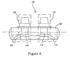
- FIG. 6 illustrates the side view of the preferred embodiment of the present invention, including an aeration equipment 100.
- the aeration equipment 100 of the embodiment comprises a first aeration apparatus 110 having a first jet aerator 114 as a power source.
- the first jet aerator 114 generally comprises an air inlet duct, a jet foundation, a gas mixing chamber, and a diffusion pipe.
- the aerating bubbles are generated beneath the water surface from a third nozzle assembly 116 connecting with the gas mixing chamber, where the air and the water are both introduced, and the third nozzle assembly 116 are arranged in a radial manner.
- the second aeration apparatus 120 has a second jet aerator 124 as the power source.
- the second jet aerator 124 also comprises an air inlet duct, a jet foundation, a gas mixing chamber, and a diffusion pipe.
- the aerating bubbles are generated beneath the water surface from the fourth nozzle assembly 126 connecting with the gas mixing chamber where the air and the water are both Introduced, and the fourth nozzle assembly 126 are arranged in a radial manner.
- the first jet aerator 114 and the second jet aerator 124 can have the same power or not.
- the first pump 111 and the second pump 121 both can also be replaced by the first jet aerator 114 and the second jet aerator 124. Even so, the composition of the whole structure and the method to control the movement of the aeration equipment are still the same. It also includes the arrangement of plurality apparatuses in, for example, a line or a circle. The purpose of the performance and the increase of the aeration range can both be accomplished effectively by utilizing the free mobility of the aeration equipment 100.
- the magnitude of the thrust of the reacting forces of the aeration equipment 100 is determined by the flow rate and the disposition of the nozzle assemblies.
- the symmetric disposition of the nozzle assemblies generates a zero thrust, the resultant of the reacting forces.
- the asymmetric disposition of the nozzle assemblies may generate a nonzero thrust, the resultant of the reacting forces, in which the thrust can be increased with the flow rate in direct ratio at the same time.
- FIG. 7 and FIG. 8 both illustrate a decoration apparatus 200 mounted on the external of the first aeration apparatus 110 and the second aeration apparatus 120 of the aeration equipment 100 of the present invention.
- the decoration apparatus 200 is, for example, a deco art, an advertisement, a display view model, a warning apparatus, or a lighting apparatus (such as a signal apparatus).
- the aforementioned apparatuses of the decoration apparatus 200 provide the aeration equipment 100 aerating, stabilizing the water quality, and advertising/entertaining in a pool in a park, or a fair, or other entertainment venue.
Landscapes
- Life Sciences & Earth Sciences (AREA)
- Chemical & Material Sciences (AREA)
- Chemical Kinetics & Catalysis (AREA)
- Environmental Sciences (AREA)
- Marine Sciences & Fisheries (AREA)
- Animal Husbandry (AREA)
- Biodiversity & Conservation Biology (AREA)
- Aeration Devices For Treatment Of Activated Polluted Sludge (AREA)
Priority Applications (1)
| Application Number | Priority Date | Filing Date | Title |
|---|---|---|---|
| EP06019163A EP1900423A1 (de) | 2006-09-13 | 2006-09-13 | Belüftungsanlage |
Applications Claiming Priority (1)
| Application Number | Priority Date | Filing Date | Title |
|---|---|---|---|
| EP06019163A EP1900423A1 (de) | 2006-09-13 | 2006-09-13 | Belüftungsanlage |
Publications (1)
| Publication Number | Publication Date |
|---|---|
| EP1900423A1 true EP1900423A1 (de) | 2008-03-19 |
Family
ID=37496989
Family Applications (1)
| Application Number | Title | Priority Date | Filing Date |
|---|---|---|---|
| EP06019163A Withdrawn EP1900423A1 (de) | 2006-09-13 | 2006-09-13 | Belüftungsanlage |
Country Status (1)
| Country | Link |
|---|---|
| EP (1) | EP1900423A1 (de) |
Cited By (5)
| Publication number | Priority date | Publication date | Assignee | Title |
|---|---|---|---|---|
| CN102823537A (zh) * | 2011-06-13 | 2012-12-19 | 虎尾科技大学 | 曝气设备 |
| CN104737968A (zh) * | 2015-03-19 | 2015-07-01 | 江苏大学 | 一种太阳能自主移动式增氧系统 |
| CN106771042A (zh) * | 2017-01-20 | 2017-05-31 | 广州三环保有限公司 | 一种带gps的环境监测供氧机 |
| CN111995058A (zh) * | 2020-08-26 | 2020-11-27 | 狄璐伟 | 一种水面环境治理用曝氧浮岛 |
| CN113046217A (zh) * | 2012-04-18 | 2021-06-29 | 生命科技股份有限公司 | 用于气体流与液体质量传递的方法和设备 |
Citations (4)
| Publication number | Priority date | Publication date | Assignee | Title |
|---|---|---|---|---|
| US3496901A (en) * | 1968-08-13 | 1970-02-24 | Acme Products Inc | Floating pump with aerator |
| JPH078987A (ja) * | 1993-01-18 | 1995-01-13 | Kubota Corp | 屋外型浄水装置 |
| WO1998022337A1 (en) * | 1996-11-20 | 1998-05-28 | Felice De Risi | Hydraulic system for manoeuvring boats, ships and crafts in general |
| GB2366218A (en) * | 2000-08-04 | 2002-03-06 | Crossland Tankers Ltd | Floating mixer for sewage treatment |
-
2006
- 2006-09-13 EP EP06019163A patent/EP1900423A1/de not_active Withdrawn
Patent Citations (4)
| Publication number | Priority date | Publication date | Assignee | Title |
|---|---|---|---|---|
| US3496901A (en) * | 1968-08-13 | 1970-02-24 | Acme Products Inc | Floating pump with aerator |
| JPH078987A (ja) * | 1993-01-18 | 1995-01-13 | Kubota Corp | 屋外型浄水装置 |
| WO1998022337A1 (en) * | 1996-11-20 | 1998-05-28 | Felice De Risi | Hydraulic system for manoeuvring boats, ships and crafts in general |
| GB2366218A (en) * | 2000-08-04 | 2002-03-06 | Crossland Tankers Ltd | Floating mixer for sewage treatment |
Cited By (7)
| Publication number | Priority date | Publication date | Assignee | Title |
|---|---|---|---|---|
| CN102823537A (zh) * | 2011-06-13 | 2012-12-19 | 虎尾科技大学 | 曝气设备 |
| CN113046217A (zh) * | 2012-04-18 | 2021-06-29 | 生命科技股份有限公司 | 用于气体流与液体质量传递的方法和设备 |
| CN113046217B (zh) * | 2012-04-18 | 2024-09-06 | 生命科技股份有限公司 | 用于气体流与液体质量传递的方法和设备 |
| CN104737968A (zh) * | 2015-03-19 | 2015-07-01 | 江苏大学 | 一种太阳能自主移动式增氧系统 |
| CN106771042A (zh) * | 2017-01-20 | 2017-05-31 | 广州三环保有限公司 | 一种带gps的环境监测供氧机 |
| CN111995058A (zh) * | 2020-08-26 | 2020-11-27 | 狄璐伟 | 一种水面环境治理用曝氧浮岛 |
| CN111995058B (zh) * | 2020-08-26 | 2022-09-13 | 江苏源泉泵业股份有限公司 | 一种水面环境治理用曝氧浮岛 |
Similar Documents
| Publication | Publication Date | Title |
|---|---|---|
| US7581716B2 (en) | Aeration equipment | |
| US10647600B2 (en) | Systems and methods for formation of biologically active granules and biologically active granules | |
| KR100759200B1 (ko) | 산소용해장치 | |
| JP5944491B2 (ja) | 汚水槽の中へガスを注入するための機器 | |
| FI120234B (fi) | Laite ja menetelmä veden ilmastamiseksi/sekoittamiseksi | |
| CN102823537A (zh) | 曝气设备 | |
| EP1900423A1 (de) | Belüftungsanlage | |
| US10654732B2 (en) | Equipment and process for massive dissolution of gases in liquids | |
| KR101127077B1 (ko) | 마이크로 버블 디퓨져 | |
| CN100378011C (zh) | 曝气设备 | |
| US7963508B1 (en) | Method and apparatus for digesting sludge | |
| US10889515B2 (en) | Systems and methods for formation of biologically active granules and biologically active granules | |
| CN2367606Y (zh) | 闭锁水域的水质净化装置 | |
| US7661660B2 (en) | Method and apparatus for aeration of a fluid | |
| CN104496016B (zh) | 一种生化充氧搅拌工艺及装置系统 | |
| JP3227567B2 (ja) | 水質浄化処理装置 | |
| US8011642B2 (en) | Cruising aerator | |
| US20210047214A1 (en) | Systems and methods for water and solids treatment | |
| US4734197A (en) | Jet aerator header assemblies and methods for use thereof in total, partial, and non-barriered oxidation ditches | |
| US20130207282A1 (en) | Aeration apparatus | |
| WO2016179327A1 (en) | Systems and methods for formation of biologically active granules | |
| RU2081578C1 (ru) | Аэратор и ферментер с аэрирующим и перемешивающим устройством | |
| JP2002346578A (ja) | 超音波を併用した水質浄化処理装置 | |
| US20060087047A1 (en) | Fluid mixing apparatus | |
| JP2004298817A (ja) | 水質浄化システムと気液混合装置 |
Legal Events
| Date | Code | Title | Description |
|---|---|---|---|
| PUAI | Public reference made under article 153(3) epc to a published international application that has entered the european phase |
Free format text: ORIGINAL CODE: 0009012 |
|
| AK | Designated contracting states |
Kind code of ref document: A1 Designated state(s): AT BE BG CH CY CZ DE DK EE ES FI FR GB GR HU IE IS IT LI LT LU LV MC NL PL PT RO SE SI SK TR |
|
| AX | Request for extension of the european patent |
Extension state: AL BA HR MK YU |
|
| AKX | Designation fees paid | ||
| STAA | Information on the status of an ep patent application or granted ep patent |
Free format text: STATUS: THE APPLICATION IS DEEMED TO BE WITHDRAWN |
|
| 18D | Application deemed to be withdrawn |
Effective date: 20080920 |
|
| REG | Reference to a national code |
Ref country code: DE Ref legal event code: 8566 |