EP1900517A1 - Appareil pour produire des structures gaufrées sur la surface d'un cylindre - Google Patents
Appareil pour produire des structures gaufrées sur la surface d'un cylindre Download PDFInfo
- Publication number
- EP1900517A1 EP1900517A1 EP06405390A EP06405390A EP1900517A1 EP 1900517 A1 EP1900517 A1 EP 1900517A1 EP 06405390 A EP06405390 A EP 06405390A EP 06405390 A EP06405390 A EP 06405390A EP 1900517 A1 EP1900517 A1 EP 1900517A1
- Authority
- EP
- European Patent Office
- Prior art keywords
- cylinder
- engraving
- stylus
- base
- distance
- Prior art date
- Legal status (The legal status is an assumption and is not a legal conclusion. Google has not performed a legal analysis and makes no representation as to the accuracy of the status listed.)
- Withdrawn
Links
Images


Classifications
-
- B—PERFORMING OPERATIONS; TRANSPORTING
- B41—PRINTING; LINING MACHINES; TYPEWRITERS; STAMPS
- B41C—PROCESSES FOR THE MANUFACTURE OR REPRODUCTION OF PRINTING SURFACES
- B41C1/00—Forme preparation
- B41C1/02—Engraving; Heads therefor
- B41C1/04—Engraving; Heads therefor using heads controlled by an electric information signal
- B41C1/045—Mechanical engraving heads
-
- B—PERFORMING OPERATIONS; TRANSPORTING
- B44—DECORATIVE ARTS
- B44B—MACHINES, APPARATUS OR TOOLS FOR ARTISTIC WORK, e.g. FOR SCULPTURING, GUILLOCHING, CARVING, BRANDING, INLAYING
- B44B3/00—Artists' machines or apparatus equipped with tools or work holders moving or able to be controlled substantially two-dimensionally for carving, engraving, or guilloching shallow ornamenting or markings
- B44B3/04—Artists' machines or apparatus equipped with tools or work holders moving or able to be controlled substantially two-dimensionally for carving, engraving, or guilloching shallow ornamenting or markings wherein non-plane surfaces are worked
Definitions
- the invention relates to an apparatus and a method for producing embossed structures in a surface of a cylinder.
- Embossing methods are known per se and have a wide range of applications. Embossing is especially produced in flat materials such as metal foils or coated metal foils.
- embossing in flat material for example, embossing dies or embossing rolls with embossed structures such as elevations and / or depressions are pressed against the material, whereupon corresponding depressions or elevations form in the material as an image of the embossed structures.
- the embossing of sheet material is advantageously carried out continuously, while the material between two embossing rollers (or an embossing roller and a counter-roller without embossed structure) is passed therethrough.
- Such a continuous process allows high production rates and thus embossing of industrial quantities, such as those incurred in the production of packaging material.
- the embossing rollers are produced for example by Molettieren.
- this process is time consuming and expensive.
- Other known methods such as specific mechanical, chemical or laser engraving methods, or the introduction of the embossed structure by embossing in a thermoplastic intermediate mold and subsequent production of a casting, share these disadvantages, allow only a poor reproducibility or require a lot of expertise and mechanical skills. Often, therefore, refrained from generating an impression only for aesthetic reasons.
- unspecific standard patterns are used due to the high costs and non-specific patterns, picture elements or logos.
- imprints to be provided material eg. For example, for packaging for consumer goods, is often already provided with a print.
- the embossing to be produced is introduced into the material to match the imprint, for. B. to recreate contours of a lettering or a picture element by the embossing and thus further emphasize.
- the embossing in the register with the imprint is difficult with the known embossing methods.
- the object of the invention is to provide a the technical field mentioned above associated device and a corresponding method, which allow a simple, fast and cost-effective production of embossing cylinders.
- the embossing structure generating device comprises an electromechanical engraving unit having a stylus movably mounted on a base of the engraving unit for working the surface, a drive for moving the stylus relative to the base, in a direction perpendicular to the surface of the cylinder, and a mechanism for Setting and maintaining a base distance between the base of the engraving unit and the surface of the cylinder.
- an electromechanical engraving unit for imaging gravure printing cylinders and associated devices are also useful and advantageous in connection with the production of embossing cylinders.
- Embossing cylinders are used for the production of imprints on flat materials, wherein no inking takes place during the embossing process, so to speak, a dummy printing is performed.
- An important difference between a gravure die and a die is the depth and geometry of the recesses (cups) created in the surface of the cylinder.
- Electromechanical engraving machines for the transmission of image information to a gravure cylinder have long been known. Achieving the required depth for embossing cylinder can not be accomplished easily with conventional engraving machines and the tools used with it, because on the one hand normal engraving systems can hardly achieve the engraving depth required for embossing cylinders and the tools used are not suitable for the required material removal. At engraving depths as needed for embossing cylinders In addition, it is particularly important to avoid cracking or to limit its consequences to the current engraving process. Another point to keep in mind is the significant chip development that goes hand in hand with the deep structures. Finally, the material to be embossed during the embossing process is claimed mechanically unequally greater than in a printing operation. This circumstance must also be taken into account in the production of the embossing cylinder.
- the engraving unit used in the context of the invention has thus been improved in particular with regard to the engraving depth required for the introduction of embossing structures and the material removal associated therewith.
- the electromechanical engraving enables rapid and cost-effective production of embossed structures on cylinder surfaces.
- copper-coated engraving cylinders are used as green bodies for the embossing cylinders, which are provided with a chromium layer after the introduction of the embossed structures to increase the hardness and resistance.
- other materials such as zinc or plastics can be processed.
- the device according to the invention advantageously comprises a controller for controlling the drive for moving the stylus as a function of input data.
- the drive signal is generated in such a way that it is suitable for generating embossing structures in the surface of the cylinder by means of the stylus.
- the controller may comprise computing means for processing the input data such that conventional image data for engraving printing cylinders, in particular halftone data, can be received as input data and transformed in such a way that Based on the transformed data, the drive signal can be generated, which is suitable for generating the embossed structures.
- the user can thus also use the existing methods, devices and computer programs for generating engraving data for the preparation of the embossing process.
- places that are printed with intense tones, at the same time receive a raised or recessed embossing.
- Halftone data can also be used, resulting in infinitely variable embossing depths.
- At least one of the embossed structures is advantageously produced in several successive engraving processes, wherein material is removed from the surface at the same position of the surface of the cylinder in the successive engraving processes by the stylus.
- the control is thus advantageously designed such that such a method is feasible.
- the amount of material to be removed per engraving process at a given depth of the structure to be introduced can thus be reduced by a multiple. This has a much longer life of the stylus and a significantly reduced risk of Stichelbruchs result. It can also be achieved with this measure engraving depths that can not be achieved in a single-step engraving.
- the mechanism for setting the basic distance is therefore preferably free of support with respect to the surface of the cylinder, d. H. during the engraving process, it does not support itself on the cylinder surface.
- the mechanism maintains the engraving system at a precisely defined distance from the cylinder surface and is such that throughout the range of cylinder circumferences used, this well-defined distance of the cutting tool can be achieved and maintained. For a good processing result, the accuracy and repeatability of the distance should be better than 10 microns.
- the engraving process can be continued seamlessly after an unexpected breaking of the cutting tool by replacing the tool, the engraving in the axial direction to a Set back before breaking the tool and restart the engraving.
- the support-free mechanism can be designed in various ways.
- the mechanism may, for. B. include an adjustable stop, which limits a spring-driven feed movement of the base of the engraving unit in the direction of the surface of the cylinder.
- Such a stop can be structurally simple form and store adjustable.
- existing solutions for conventional sliding feet can essentially be taken over and only have to be supplemented by the adjustable stop.
- the spring-driven delivery of the engraving unit is retained.
- the non-support mechanism may additionally or alternatively include means for measuring a distance between the base of the engraving unit and the surface of the cylinder and a drive for adjusting the base distance between the base of the engraving unit and the surface of the cylinder depending on the measured distance.
- the measurement is carried out in particular contactless, for example by an optical sensor, a capacitive sensor or by a laser interferometer.
- the setting takes place, for example, by means of a fast servomotor, which acts on an adjusting device of the stop or directly on the base.
- the adjustable storage or the stop are in both cases designed so that the engraving process occurring retroactive forces can be taken from the base.
- the engraving signal is reshaped, ie that the signal amplitude corresponding to the measured distance is amplified or attenuated - in this case, the basic distance is thus already changed at the level engraving signal.
- the latter possibility can be particularly simple and inexpensive to implement without additional mechanical parts, but it - depending on the tolerances in the cylinder diameter - a reduction in the maximum engraving depth of the engraving system result.
- an already completed material removal at the currently processed position can be taken into account by taking into account the input data during readjustment.
- the measured distance is thus corrected by the already performed removal. This measure is indicated in a multi-level engraving and also allows further engraving after an interruption, z. B. after a break of the stylus.
- a profile of the surface of the cylinder can be measured out and stored. This is then taken into account when adjusting the basic distance.
- the profile reflects both the geometry of the unprocessed cylinder surface and inaccuracies in cylinder centering. Its consideration in determining the basic distance to be set ensures that engraving of the concrete cylinder surface is always followed and that the given engraving depths are precisely maintained over the entire cylinder surface. A puncture or other interruptions do not affect the precise engraving, because it can always fall back on the original profile of the cylinder.
- the measurement of the cylinder profile also allows the processing of difficult workpieces, eg. B. cylinders with increasing or changing diameter in the axial direction.
- this can also be kept constant during an entire engraving process, wherein between successive engraving operations, the basic distance between the base of the engraving unit and the surface of the cylinder is in each case reduced by a predetermined value, in particular as a function of the input data.
- the predetermined value can always be the same or different changes can be made between different engraving operations.
- the values can be selected independently of the embossing structures to be generated or else depending on the input data. The latter opens up the possibility of choosing the values such that, for example, the removal of material in the individual engraving processes remains approximately constant or that only chips are produced during processing which can be removed without difficulty.
- a smoothing engraving can also be carried out in the surface of the cylinder before the embossing structures are produced.
- at least a substantial part of the surface of the cylinder is processed by the stylus before generating the embossed structures, wherein the distance between the stylus and an axis of rotation of the cylinder predetermined by the engraving device is kept constant.
- the feed rate is chosen in view of a long life of the stylus.
- the engraving depth is adjusted so that the stylus remains in contact with it for one full revolution of the cylinder and over its entire length.
- the untreated cylinder may have a low quality surface in relation to its roughness and deviations from a perfect cylinder, and therefore all operations prior to introduction of the embossing structures must be much less precise and thus more cost effective and faster.
- the device may additionally comprise a conventional sliding foot.
- the device is in this case designed such that it can be switched over between an embossing cylinder and a pressure cylinder mode. This means that when creating embossed structures, the support-free mechanism for setting the basic spacing is used, while the gliding foot is used when producing intaglio cups.
- the slide foot can be retracted, folded away or removed for embossing cylinder mode.
- the device has characteristics of edge steepness that meets the requirements of engraving in the imaging of gravure cylinders.
- the engraving system can be operated in the frequency engraving mode necessary for the imaging of gravure cylinders.
- a multi-level engraving is also possible with a supporting mechanism for setting the base distance.
- a circular engraving is performed, in which the same track is processed during at least two complete (consecutive) cylinder revolutions.
- the working depth of the burin is thereby increased from a first approach to a second approach in the same track (and for any further rounds).
- the axial position of the engraving system is maintained. As soon as along the corresponding circular line the desired engraving depth is reached, the engraving system is moved to the next track, whereupon it can be processed in the same way.
- the base distance between the base of the engraving unit and the surface of the cylinder can be adjusted by means of a sliding foot supported on a still unprocessed area of the surface.
- the basic distance is therefore maintained from the first handling to the second handling (and also in other possible passages).
- the increase of the working depth of the stylus takes place by a modification of the drive signal.
- the drive signal is superimposed, for example, with a correspondingly rising signal, or amplified with a stepwise increasing gain factor.
- the embossed structures should be such that the embossing process proceeds as gently as possible in order to prevent the material from breaking or becoming too thin at certain points. It is therefore advantageous if, when generating the drive signal as a function of the input data, the input data representing an image are modified with regard to smoother transitions between regions of the image of different brightness values. This can be done in particular by a soft-focus transformation. In this process, sudden transitions in the brightness value are distributed over a larger image area, which also results in smoother transitions in the embossed structure and finally in the embossing.
- the embossing takes place between two embossing cylinders which interact as die and male.
- the input data for one of the cylinders can be inverted.
- the image represented by the input data is compressed and / or stretched in order to form the structures on the matrix and the male mold correspondingly in such a way that no squeezing of the material to be embossed takes place.
- the upsetting or stretching can by known and many Devices for producing a print template available algorithms are performed, which are commonly used for widening or narrowing of fonts.
- embossed structures may be produced which comprise one or more substantially continuous engraved characters composed of a plurality of adjacent tracks on the surface of the cylinder.
- conventional gravure forms of the stylus is excited by a sinusoidal frequency. This sine frequency is superimposed on a modulated video signal.
- Conventional intaglio printing forms therefore have a large number of distanced cells, each of which absorbs ink and releases it to the paper during the printing process. Because the color dissolves and because the eye usually does not perceive the individual halftone dots, the printed image appears visually coherent.
- a method for engraving large continuous areas of gravure cylinders for example, from EP 0 805 957 B1 (MDC Max Duschwyler AG) known.
- a pulse width or pulse width modulated drive signal is generated.
- the usual sinusoidal signal is omitted.
- this method is particularly well suited for the production of embossing cylinders.
- intermediate values can also be engraved in a simple manner. These intermediate values correspond to areas of the embossed structure which have a smaller depth (or height) than the maximum depth (or maximum height).
- the chip produced during the production of embossed structures can become very long, in particular if the engraved structures are non-planar and comprise oblong tracks in the direction of rotation of the machined cylinder.
- problems may arise, for example, when the chip is caught in a suction device or wrapped around parts of the machine or the embossing cylinder.
- structures are created in the surface of the cylinder for breaking a chip created during machining of the surface of the cylinder.
- the structures for breaking the chip are, in particular, small-scale structures with a depth that is less than a depth of the surrounding embossed structure. It has been shown that predetermined breaking points in the span can already be created by small depth differences. It is therefore basically sufficient to retract the engraving tool in the area of large areas at regular or irregular intervals, so that the diameter of the chip is slightly reduced at the corresponding point.
- the computing means are preferably designed and controlled in such a way that data for generating structures for breaking a chip resulting during engraving are automatically recorded in the transformed data.
- the controller which receives and processes the data necessary for the introduction of the embossed structures, examines these data for large areas to be engraved and, if the areas exceed a predetermined size, at suitable intervals modify the data such that the engraving tool briefly withdrawn so far that the desired reduction in the diameter of the chip or its complete demolition is achieved.
- the device according to the invention comprises a device for extracting chips, wherein a suction opening of this device is arranged in the region of the stylus at the base of the engraving unit.
- the opening is designed so that at this point the exhaust air undergoes maximum acceleration, so that in particular long, thick chips can be sucked in the region of origin, without them getting caught and clog the suction.
- the stylus advantageously has a tool angle of 90-140 °, preferably 90-120 °.
- the tool angle refers to those Angle in which the cutting flanks of the tool are in relation to each other.
- the feed rate is chosen to optimize the machining speed while maintaining unwanted bumps and indentations on the engraved surface at a level that does not interfere with the subsequent stamping operation.
- feed distances of up to 50 ⁇ m are advantageous.
- unwanted structures of 14.5 ⁇ m depth are created.
- the relatively small angle of maximum 140 °, preferably 120 ° the depth of such structures can thus be kept within limits. It has also been shown that tool angles in the specified range at the same time allow the production of robust stylus.
- the stylus advantageously has a lower tapering portion and an upper portion adjoining the lower portion above, wherein delimiting edges of the upper portion enclose an angle that is smaller as the tool angle, which is enclosed by the edges in the tapered part.
- the angle is in particular at least 45 °, preferably at least 60 °, smaller than the tool angle.
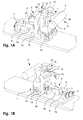
- FIG. 1 shows an exemplary embodiment of a engraver unit according to the invention, which is suitable for both the engraving and the embossing mode.
- the engraving unit is mounted in a manner known per se on a carriage by means of which it can be moved relative to a cylinder 5 to be machined, for example with a surface 5a made of copper to be machined.
- the engraving unit comprises a lower mounted engraving system 1. This is arranged pivotably about an axis 1a on a base plate 1b. At the engraving 1 a sliding foot 2 is adjustably attached. The adjustment takes place via an adjusting mechanism 3 with an adjusting spindle 3a. Also on the engraving an electrically operated stylus 4 is attached.
- the deflection of the stylus in a direction perpendicular to the surface 5a of the cylinder 5 takes place in a manner known in electromechanical engraving systems.
- the stylus is arranged in particular on a lever which is mounted on a torsion spring, and which can be deflected by overcoming the spring force by means of an electromagnet.
- the lowering of the engraving system 1 by pivoting about the axis 1a is effected by an electric feed unit.
- This comprises a mounted on the base plate 1 b electric motor 6 and connected to the drive axle of the motor 6, also mounted on the base plate 1b gearbox 7.
- the output shaft of the transmission 7 is connected to a feed spindle 8 with external thread on which a spring mechanism 9 hinged is.
- the spring mechanism 9 comprises a nut segment 9a with an internal thread, which cooperates with the external thread of the feed spindle 8 such that the nut segment 9a can be moved forward or backward in a direction substantially perpendicular to the surface of the cylinder 5.
- the rear end of a lever 9b is articulated with integrated spring elements.
- this lever 9b can be reduced by overcoming the spring force.
- the lever 9b is hinged at its front end to the back of the engraving system 1.
- the spring mechanism 9 thus provides the necessary contact pressure of the engraving system 1 on the surface 5 a of the cylinder 5 ready.
- the sliding foot 2 is presented with the aid of the adjusting mechanism 3 so far that a predetermined basic distance between the stylus 4 and the surface 5 a of the cylinder 5 is defined.
- the engraving system 1 with the sliding foot 2 located in the engraving position can then be lowered completely onto the cylinder surface 5a by the electric feed unit, so that the contact pressure prescribed for the engraving is achieved. Thereafter, the engraving of the printing cylinder is possible, wherein the basic distance between engraving 1 and cylinder surface 5a is continuously tracked using the supported on the cylinder surface 5a Gleitfusses 2.
- an embossed structure takes place in the illustrated embodiment in several steps, ie the desired depth of the structures is achieved by repeated processing, wherein the processing depth is increased in each case from one processing step to the next.
- the load on the cutting tool can be kept below a maximum load.
- the surface is due to the already introduced structure such that the Gleitfuss 2 can not be used for the determination of the distance between the cylinder surface 5a and 4 Stichel, since it penetrates into the previously introduced embossed structure, which is the distance to the cylinder surface 5a changed and may even lead to damage of the cylinder 5 or the Gleitfusses 2.
- a fine delivery mechanism 10 for the engraving system 1 is used instead.
- This mechanism comprises a frame 11 which is fixedly mounted on the engraving system and extends rearwardly.
- the rear traversing cross member a through opening is formed with internal thread, which receives a precision feed spindle 12 with external thread.
- an adjustment handle 13 is attached at the rear end of the feed spindle 12.
- a ball is attached at the front end of the feed spindle 12.
- This ball acts on a pressure plate 14, which is firmly connected by means of a yoke 15 with the base plate 1 b of the engraving unit.
- the feed spindle 12 and the pressure plate 14 together form a stop, by means of which the movement of the engraving system 1 on the surface 5 a of the cylinder 5 can be limited. By turning the feed spindle 12, the stop and thus the front end position of the engraving system 1 can be finely adjusted.
- a bracket 16 for holding a scraper on the engraving system 1 is rotatably mounted.
- the attached to the bracket 16 diamond scraper is pressed by arranged at the lateral attachment points of the bracket 16 springs and by the weight of the bracket 16 on the surface 5 a of the cylinder 5 and serves unwanted, over the surface 5 a protruding structures by the Engraving process have been created to remove.
- the scraper is not used in embossing mode.
- the sliding foot 2 is pulled back by an adjusting device (not shown).
- the feed spindle 12 is then pre-rotated until the engraving system 1 is still retained so far that the stylus 4 remains just as far removed from the cylinder surface 5a when lowered by the feed unit that he these are not touched.
- the adjusting handle 13 By turning the adjusting handle 13, the cutting depth can now be determined very precisely and increased accordingly in each subsequent processing step.
- the adjustment of the basic distance takes place with the aid of a video detection system which can optically detect the depressions generated in the cylinder surface.
- the engraving system is first to be moved onto the cylinder with a coarse feed mechanism. Subsequently, the surface of the cylinder is scribed with the tip of the stylus, wherein only that portion of the stylus penetrates into the material, which has a clearly defined and constant tool angle with respect to the stylus tip. This ensures that the engraving depth can be calculated directly from the width of the recess produced optically by means of the video acquisition system using the tool angle.
- the distance between the engraving system and the cylinder surface is then corrected to the predetermined basic distance with the aid of the fine delivery mechanism.
- the increase in the cutting depth between subsequent processing steps is carried out by the precisely actuated Feinzu einsmechanismus, without further distance measurements are performed.
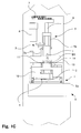
- FIG. 2 shows a schematic representation of the control of the engraving unit according to the invention for producing embossing and gravure printing structures.
- the base plate 1b of the engraving unit is fastened to the carriage 20, by means of which it can be moved relative to the cylinder 5, in particular along a direction 21 parallel to the cylinder axis.
- the engraving system 1 is moved by the force acting on the spring mechanism 9 drive 6 along a direction 22 to the cylinder 5 and away from it.
- the stylus 4 which is driven by a drive 23 in itself known manner electromechanically, in particular electromagnetically, can be actuated so that it penetrates into the surface 5 a of the cylinder 5 for engraving.
- the sliding foot 2 which can be moved by a further drive 24 in small steps from a front position (shown in FIG. 2) to a rear position.
- a distance sensor 25 Further arranged on the engraving system 1 is a distance sensor 25 with a mechanical contact element 26, which can contact the surface 5 a of the cylinder 5 with its free front end. The contact element 26 can be withdrawn if necessary.
- a further actuator 27 is also arranged on the base plate 1 b of the engraving unit. This cooperates with a stop 28 on the engraving system 1, so that the movement of the engraving system in the direction 22 is limited to the surface 5a of the cylinder, while a movement away from the cylinder surface 5a is not affected backwards by this device.
- the above-described drives are controlled by a controller 40.
- This includes an input interface 41 for receiving input data, a central processing unit (CPU) 42 receiving data from the input interface, a memory 43 cooperating with the CPU 42, a peripheral interface 44 for communicating with the distance sensor 25 and the drivers 6 , 24, 27, a signal processor 45 and a drive signal generator 46, the signal processor 45 receives an input signal and control commands from the CPU 42 and passes the signal to the drive signal generator 46 after processing. The latter generates a signal which is suitable for direct control of the drive 23 for the stylus 4.
- CPU central processing unit
- the sliding foot 2 is first retracted by the CPU 42 controlled by the drive 24 to the rear. Subsequently, the engraving system 1 is moved so far on the surface 5a of the cylinder 5 that the tip of the stylus 4 in its rest position from the axis of rotation of the cylinder 5 has a distance which the average diameter of the cylinder 5 plus the expected diameter tolerance and a maximum axis error equivalent.
- the carriage 20 is moved to an axial initial position, after which the contact element 26 of the distance sensor 25 travels through the entire cylinder surface 5a by rotating the cylinder 5 and moving the carriage 20 axially.
- the distance between the engraving system 1 and the cylinder surface 5a is measured continuously or stepwise, transmitted via the peripheral interface 44 to the CPU 42 and stored by the latter in the memory 43.
- the memory contains a distance profile of the entire cylinder surface 5a, in which both local deviations of the cylinder diameter and non-circularities due to axis errors are taken into account.
- the contact element 26 of the distance sensor 25 is now withdrawn, and the carriage 20 is moved back to its initial position.
- the basic distance of the engraving system 1 from the cylinder surface 5a is now adjusted depending on the recorded distance profile and the received via the input interface 41 and stored in the memory 43 pressure data by the drive 27 at the stop 28 that optimally to be generated in a first engraving recesses, d , H. with the best possible quality and lowest possible wear of the stylus 4, can be engraved.
- the distance of the engraving system 1 from the cylinder surface 5a is continuously readjusted by the servo-formed drive 27 depending on the recorded distance profile. As a result, surface inaccuracies and axis errors of the cylinder bearing are compensated.
- the engraving itself can be done in a conventional manner along a helix (helical), or adjacent tracks are engraved (ring engraving).
- the carriage 20 After completion of the first engraving process, the carriage 20 is moved with the engraving unit back to its initial position. Subsequently, a new basic distance between the engraving system 1 and the cylinder surface 5a is set by the drive 27. In the determination of the new basic distance, in turn, the distance profile and the pressure data are used, whereby it is also taken into account which depressions have already been generated in the surface 5a during the first engraving process.
- the second engraving process on the one hand, further, previously unprocessed Adjusting the cylinder surface 5a processed, on the other hand depressions in already previously processed areas of the cylinder 5 - as necessary - further deepened.
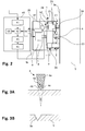
- FIG. 3A shows an embodiment of a stylus 4 which is suitable for use in the engraving unit according to the invention for producing embossed structures.
- the stylus 4 is formed by a diamond, which is prismatic ground. It comprises a shank 4a, which is adjoined by a front cutting edge 4b in the working direction and a free edge 4c in the working direction. Both the cutting edge 4b and the free edge 4c each comprise a rear portion and a front portion adjoining the front thereof, the two front portions of the cutting edge 4b and the free edge 4c converging at a tool angle ⁇ .
- the cutting lines between the cutting edge 4b and the free edge 4c form the cutting tip 4d of the stylus 4.
- the rear portions include an angle ⁇ , which is smaller than the tool angle ⁇ .
- FIG. 3B shows a recess 5b formed in the surface of the embossing cylinder 5 with the stylus 4 according to FIG. 4A.
- the recess 5b with a minimal areal extent has walls according to the geometry of the stylus 4, which initially starts steeply from the surface 5a of the cylinder 5 run inwards. This is followed by converging wall sections.
- the illustrated recess 5b can be made even deeper in a further engraving process, wherein the area claimed by the recess 5b on the cylinder surface 5a will increase only insignificantly. It can thus be generated with the illustrated stylus 4 deep embossed structures with small surface area. Accordingly, embossing cylinders, which are produced according to the method according to the invention, can be used to produce embossments with high detail resolution while at the same time having a large embossing depth or height.
- FIGS 4A-4D schematically illustrate the processing of an image signal to a drive signal for generating embossed patterns in a die and a male.
- the image signal 50 corresponds to an image signal as provided for driving engraving machines. It has an amplitude A (t) variable with time t, a high amplitude representing a high color density, the amplitude zero corresponding to full white (no color output and thus no engraving).
- the image signal 50 is a halftone signal and includes portions corresponding to an intermediate tone between white and full black.
- the image signal 50 comprises a plurality of temporally successive sections 50.1... 50.8, with sections 50.2, 50.4, 50.6, 50.8 of constant amplitude A alternating with sections 50.1, 50.3, 50.5, 50.7, in which the amplitude A changes at a constant rate, d. H. decreases or increases.
- an inverted image signal 51 is first generated (see FIG. 4B):
- the intermediate tones are correspondingly inverted, 40% of fully black becomes e.g. B. 60% full black.
- the image signal 50 and the inverted image signal 51 undergo further transformation (see FIG. 4C), with 50 transitions to darker portions (larger values of A) being temporally preferred by a given offset t o1 in the case of the original image signal, transitions becoming brighter Sections (smaller values of A) are delayed in time by the predetermined offset t o1 .
- transitions to brighter sections are delayed in time by the predetermined offset t o1
- transitions to darker sections are delayed in time by the predetermined offset t o1 .
- the transformed signal 52 obtained from the original image signal 50 thus has a higher black content than the original image signal 50, whereas the transformed signal 53 obtained from the inverted image signal 51 has a higher white content compared to the inverted image signal 51. Due to the symmetry of the made Transformations, the image size of the embossed structure in comparison with the original image signal 50 is maintained.
- the transformation can be realized, for example, with algorithms for compressing fonts. Such algorithms are well known from the pre-press or from existing controls for engraving machines and can be used in this field for the application according to the invention.
- the transformed signals 52, 53 are finally subjected to a blur transformation.
- the sections 52.1, 52.3, 52.5, 52.7; 53.1, 53.3, 53.5, 53.7 with alternating amplitude A at the expense of sections 52.2, 52.4, 52.6, 52.8; 53.2, 53.4, 53.6, 53.8 is extended with constant amplitude A, ie the beginning of the rise or fall of the signal is advanced by a predetermined offset t o2 and the section is also extended by this offset.
- the transitions between constant and alternating sections are rounded off by inserting intermediate values that create a smooth transition.
- the drive signals 54, 55 generated by the described transformations for producing embossed patterns in a die are shown in FIG. 4D. They are particularly suitable for operating an engraving machine, which can engrave large continuous areas with coherent areas composed of several tracks. Such a system is as mentioned above, for example in the EP 0 805 957 B1 (MDC Max Duschwyler AG).
- FIG. 4E shows a cross section through the die 60 or male part 61 produced by the drive signal.
- the elevations of the male part 61 are narrower than the corresponding recesses of the female part 60. Accordingly, the material to be embossed between the female part 60 and the male part 61 becomes the embossing process not squeezed, but can be suitably received between the opposing surfaces. The rounding of the transitions also reduces the risk of damaging the material to be embossed during the embossing process.
- FIGS. 5A-5E show a schematic representation of a multistage process according to the invention for producing an embossed structure. As an example of that too generating structure are used in the die 60 according to Figure 4E produced wells. To be able to produce good imprints will be an advantage
- Embossed structures with depths of 100 - 300 microns, generated.
- FIG. 5A shows the still unprocessed section of the die 60. Dashed lines indicate the structure to be produced. The process will take place in several stages, whereby material will be removed up to a certain maximum depth (levels 70.1 ... 70.4). In the example chosen, the distances of the first plane 70.1 to the surface 60a of the die 60 and adjacent planes 70.1... 70.4 are each selected to be the same size. The planes 70.1... 70.4 have, for example, a distance of 55, 110, 165 or 220 ⁇ m from the original cylinder surface.
- Figures 5B, 5C, 5D respectively show the partially machined portion of the die 60 after the first, second and third engraving operations.
- the same drive signal is used for each engraving process, only the distance of the engraving system from the (original) cylinder surface is changed.
- the respectively removed material 71.1, 71.2, 71.3 is shown with a wide hatching.
- the processing takes place in each case up to a depth specified by the corresponding level 70.1... 70.3.
- the maximum machining depth, which the stylus used has to perform thus corresponds to the distance between two planes 70.1... 70.3, namely 55 ⁇ m, and is therefore fixed.
- Figure 5E shows the final result. After removal of the material 71.4 in the fourth engraving step, the predetermined shape is reached.
- the planes to which engraving may also be selected depend on the recesses to be produced, or so that the material to be abraded in each engraving process remains approximately constant from step to step.
- the multi-stage engraving may comprise a plurality of successive engraving operations, wherein in each process by a helical or circular engraving in a conventional manner substantially the entire cylinder surface is processed (with the exception of those points which are not to edit or in which the desired Engraving depth has already been reached).
- This allows a multi-stage engraving even when using a supporting mechanism for adjusting the base distance, such as a sliding foot.
- the sliding foot (or a contact element of another supporting mechanism) is supported on the still unprocessed area of the cylinder surface.
- the working depth of the stylus is gradually increased from handling to handling in the same track.
- the drive signal can be superimposed with a correspondingly rising signal or amplified with a stepwise increasing gain factor. If the full engraving depth is not required along a certain ring line, then the maximum number of engraving processes does not have to be carried out there, but after reaching the desired depth along the entire ring line, the engraving system can be moved to the next line and start processing there.
- this can also be produced in just one engraving step.
- the surface of the embossing cylinder can, for example, be provided with a layer of chromium for greater durability. Subsequently, the cylinder is ready for use. It can be used in particular in a conventional printing press, as it is used for gravure printing. The gravure printing and the embossing can be performed in the same printing press, but with separate cylinders, in particular by directly successively arranged printing units. This allows for efficient printing and embossing, where desired, the printed pixels and imprints can be precisely registered.
- an apparatus and a method are provided by the invention, which allow a simple, fast and cost-effective production of embossing cylinders.
Landscapes
- Engineering & Computer Science (AREA)
- Mechanical Engineering (AREA)
- Manufacturing & Machinery (AREA)
- Manufacture Or Reproduction Of Printing Formes (AREA)
- Shaping Of Tube Ends By Bending Or Straightening (AREA)
- Machines For Manufacturing Corrugated Board In Mechanical Paper-Making Processes (AREA)
Priority Applications (4)
| Application Number | Priority Date | Filing Date | Title |
|---|---|---|---|
| EP06405390A EP1900517A1 (fr) | 2006-09-12 | 2006-09-12 | Appareil pour produire des structures gaufrées sur la surface d'un cylindre |
| PCT/CH2007/000434 WO2008031242A2 (fr) | 2006-09-12 | 2007-09-03 | Dispositif de formation de structures de gaufrage dans une surface d'un cylindre |
| RU2009113606/12A RU2009113606A (ru) | 2006-09-12 | 2007-09-03 | Устройство для создания структур тиснения в поверхности цилиндра |
| EP07800626A EP2061659B1 (fr) | 2006-09-12 | 2007-09-03 | Dispositif de formation de structures de gaufrage dans une surface d'un cylindre |
Applications Claiming Priority (1)
| Application Number | Priority Date | Filing Date | Title |
|---|---|---|---|
| EP06405390A EP1900517A1 (fr) | 2006-09-12 | 2006-09-12 | Appareil pour produire des structures gaufrées sur la surface d'un cylindre |
Publications (1)
| Publication Number | Publication Date |
|---|---|
| EP1900517A1 true EP1900517A1 (fr) | 2008-03-19 |
Family
ID=37768755
Family Applications (2)
| Application Number | Title | Priority Date | Filing Date |
|---|---|---|---|
| EP06405390A Withdrawn EP1900517A1 (fr) | 2006-09-12 | 2006-09-12 | Appareil pour produire des structures gaufrées sur la surface d'un cylindre |
| EP07800626A Not-in-force EP2061659B1 (fr) | 2006-09-12 | 2007-09-03 | Dispositif de formation de structures de gaufrage dans une surface d'un cylindre |
Family Applications After (1)
| Application Number | Title | Priority Date | Filing Date |
|---|---|---|---|
| EP07800626A Not-in-force EP2061659B1 (fr) | 2006-09-12 | 2007-09-03 | Dispositif de formation de structures de gaufrage dans une surface d'un cylindre |
Country Status (3)
| Country | Link |
|---|---|
| EP (2) | EP1900517A1 (fr) |
| RU (1) | RU2009113606A (fr) |
| WO (1) | WO2008031242A2 (fr) |
Cited By (1)
| Publication number | Priority date | Publication date | Assignee | Title |
|---|---|---|---|---|
| DE112013002312B4 (de) * | 2012-05-04 | 2020-11-05 | Hell Gravure Systems Gmbh & Co. Kg | Gravierorgan zur Gravur von Druckformen |
Citations (6)
| Publication number | Priority date | Publication date | Assignee | Title |
|---|---|---|---|---|
| EP0741008A2 (fr) * | 1995-05-02 | 1996-11-06 | MDC Max Dätwyler Bleienbach AG | Appareil pour graver des cylindres d'impression |
| DE19635831A1 (de) * | 1996-09-04 | 1998-03-05 | Hell Ag Linotype | Verfahren und Einrichtung zur Steuerung eines Gravierorgans |
| DE19920207A1 (de) * | 1999-05-03 | 2000-11-09 | Heidelberger Druckmasch Ag | Verfahren zum Betrieb einer Graviermaschine |
| DE19952994A1 (de) * | 1999-11-04 | 2001-05-10 | Heidelberger Druckmasch Ag | Verfahren zur Gravur von Druckzylindern |
| US6515772B1 (en) * | 1993-02-25 | 2003-02-04 | Mdc Max Daetwyler Ag | Apparatus and method for engraving a gravure printing cylinder |
| DE10149828A1 (de) * | 2001-10-09 | 2003-04-30 | Hell Gravure Systems Gmbh | Verfahren zur Lagekorrektur eines Gravierorgans |
-
2006
- 2006-09-12 EP EP06405390A patent/EP1900517A1/fr not_active Withdrawn
-
2007
- 2007-09-03 WO PCT/CH2007/000434 patent/WO2008031242A2/fr not_active Ceased
- 2007-09-03 EP EP07800626A patent/EP2061659B1/fr not_active Not-in-force
- 2007-09-03 RU RU2009113606/12A patent/RU2009113606A/ru not_active Application Discontinuation
Patent Citations (6)
| Publication number | Priority date | Publication date | Assignee | Title |
|---|---|---|---|---|
| US6515772B1 (en) * | 1993-02-25 | 2003-02-04 | Mdc Max Daetwyler Ag | Apparatus and method for engraving a gravure printing cylinder |
| EP0741008A2 (fr) * | 1995-05-02 | 1996-11-06 | MDC Max Dätwyler Bleienbach AG | Appareil pour graver des cylindres d'impression |
| DE19635831A1 (de) * | 1996-09-04 | 1998-03-05 | Hell Ag Linotype | Verfahren und Einrichtung zur Steuerung eines Gravierorgans |
| DE19920207A1 (de) * | 1999-05-03 | 2000-11-09 | Heidelberger Druckmasch Ag | Verfahren zum Betrieb einer Graviermaschine |
| DE19952994A1 (de) * | 1999-11-04 | 2001-05-10 | Heidelberger Druckmasch Ag | Verfahren zur Gravur von Druckzylindern |
| DE10149828A1 (de) * | 2001-10-09 | 2003-04-30 | Hell Gravure Systems Gmbh | Verfahren zur Lagekorrektur eines Gravierorgans |
Cited By (1)
| Publication number | Priority date | Publication date | Assignee | Title |
|---|---|---|---|---|
| DE112013002312B4 (de) * | 2012-05-04 | 2020-11-05 | Hell Gravure Systems Gmbh & Co. Kg | Gravierorgan zur Gravur von Druckformen |
Also Published As
| Publication number | Publication date |
|---|---|
| EP2061659B1 (fr) | 2011-05-25 |
| WO2008031242A3 (fr) | 2008-07-10 |
| WO2008031242A2 (fr) | 2008-03-20 |
| RU2009113606A (ru) | 2010-10-20 |
| EP2061659A2 (fr) | 2009-05-27 |
Similar Documents
| Publication | Publication Date | Title |
|---|---|---|
| EP0906193B1 (fr) | Procede de production de plaques a gaufrer | |
| DE69629279T2 (de) | Verfahren und vorrichtung zum gravieren | |
| EP3822080B1 (fr) | Procédé de détermination des paramètres d'impression d'une machine d'impression et banc d'essai | |
| DE69936407T2 (de) | Verfahren zur Werkzeugeinstellung in einer Blechherstellungsmaschine | |
| EP4182099B1 (fr) | Tôle d'acier laminée à écrouissage superficiel, rouleau d'écrouissage superficiel et procédé de production de tôle d'acier laminée à écrouissage superficiel | |
| EP2092991B1 (fr) | Matrice à plier pour une presse à plier, notamment presse plieuse et procédé de pliage d'une pièce | |
| DE4203940A1 (de) | Vorrichtung zur ermittlung der kontaktposition zweier walzen mit parallelen achsen | |
| DE102012006558B4 (de) | Verfahren zur Herstellung einer Flexodruckform | |
| DE2508985A1 (de) | Verfahren und vorrichtung zur herstellung eines tiefdruckzylinders | |
| DE102012011893B4 (de) | Verfahren und Vorrichtung zum Tuschieren eines Werkzeuges in einer Presse | |
| EP0353479A1 (fr) | Procédé et dispositif pour réduire la charge de presse dans une presse à découper comportant des butées fixes | |
| DE69025809T2 (de) | Laserstrahlbearbeitung und Gerät dazu | |
| EP2061659B1 (fr) | Dispositif de formation de structures de gaufrage dans une surface d'un cylindre | |
| DE102011054776B4 (de) | Markierprägevorrichtung für die Beschriftung auf Holz und Verfahren zum Prägen | |
| EP2523809B1 (fr) | Procédé et dispositif destinés à optimiser la position relative d'au moins deux cylindres d'impression | |
| DE69704391T2 (de) | Walzen ringförmiger Werkstücke | |
| DE4318200C2 (de) | Verfahren zum Einstellen der Berührung zweier im Abstand zueinander verstellbarer Walzen | |
| EP1386727B1 (fr) | Procédé pour améliorer la qualité d'une image gravée dans un cylindre d'impression | |
| WO2006131088A2 (fr) | Procede d'application durable d'une image a echelle de gris sur une surface mate | |
| DE2439420A1 (de) | Verfahren und vorrichtung zum rollen von verzahnungen | |
| DE19710005A1 (de) | Verfahren und Einrichtung zur Gravur von Druckzylindern | |
| DE69102058T2 (de) | Vorrichtung zum Beschreiben, Schneiden und Stanzen von Bahnmaterial. | |
| DE60121905T2 (de) | Verfahren zum Herstellen mindestens einer Einprägung auf der Oberfläche eines Metalbehälters | |
| EP1638711B1 (fr) | Machine et procede d'estampage de pieces | |
| DE102021131839B4 (de) | Verfahren zum Herstellen eines Presswerkzeugs mit tiefer Strukturierung |
Legal Events
| Date | Code | Title | Description |
|---|---|---|---|
| PUAI | Public reference made under article 153(3) epc to a published international application that has entered the european phase |
Free format text: ORIGINAL CODE: 0009012 |
|
| AK | Designated contracting states |
Kind code of ref document: A1 Designated state(s): AT BE BG CH CY CZ DE DK EE ES FI FR GB GR HU IE IS IT LI LT LU LV MC NL PL PT RO SE SI SK TR |
|
| AX | Request for extension of the european patent |
Extension state: AL BA HR MK YU |
|
| AKX | Designation fees paid | ||
| REG | Reference to a national code |
Ref country code: DE Ref legal event code: 8566 |
|
| STAA | Information on the status of an ep patent application or granted ep patent |
Free format text: STATUS: THE APPLICATION IS DEEMED TO BE WITHDRAWN |
|
| 18D | Application deemed to be withdrawn |
Effective date: 20080920 |