EP1900569B1 - Dispositif à rochet pour étirer des objets pouvant être enroulés - Google Patents
Dispositif à rochet pour étirer des objets pouvant être enroulés Download PDFInfo
- Publication number
- EP1900569B1 EP1900569B1 EP20070018283 EP07018283A EP1900569B1 EP 1900569 B1 EP1900569 B1 EP 1900569B1 EP 20070018283 EP20070018283 EP 20070018283 EP 07018283 A EP07018283 A EP 07018283A EP 1900569 B1 EP1900569 B1 EP 1900569B1
- Authority
- EP
- European Patent Office
- Prior art keywords
- bolt
- catch
- locking
- ratchet
- ratchet device
- Prior art date
- Legal status (The legal status is an assumption and is not a legal conclusion. Google has not performed a legal analysis and makes no representation as to the accuracy of the status listed.)
- Not-in-force
Links
- 238000003780 insertion Methods 0.000 claims description 4
- 230000037431 insertion Effects 0.000 claims description 4
- 230000007935 neutral effect Effects 0.000 claims 6
- 230000014759 maintenance of location Effects 0.000 claims 2
- 230000000903 blocking effect Effects 0.000 description 7
- 238000006073 displacement reaction Methods 0.000 description 2
- 210000003746 feather Anatomy 0.000 description 2
- 230000000712 assembly Effects 0.000 description 1
- 238000000429 assembly Methods 0.000 description 1
- 210000000078 claw Anatomy 0.000 description 1
- ZINJLDJMHCUBIP-UHFFFAOYSA-N ethametsulfuron-methyl Chemical compound CCOC1=NC(NC)=NC(NC(=O)NS(=O)(=O)C=2C(=CC=CC=2)C(=O)OC)=N1 ZINJLDJMHCUBIP-UHFFFAOYSA-N 0.000 description 1
- 238000012423 maintenance Methods 0.000 description 1
- 238000004804 winding Methods 0.000 description 1
Images



Classifications
-
- B—PERFORMING OPERATIONS; TRANSPORTING
- B60—VEHICLES IN GENERAL
- B60P—VEHICLES ADAPTED FOR LOAD TRANSPORTATION OR TO TRANSPORT, TO CARRY, OR TO COMPRISE SPECIAL LOADS OR OBJECTS
- B60P7/00—Securing or covering of load on vehicles
- B60P7/06—Securing of load
- B60P7/08—Securing to the vehicle floor or sides
- B60P7/0823—Straps; Tighteners
- B60P7/083—Tensioning by repetetive movement of an actuating member
Definitions
- the invention relates to a ratchet assembly for tensioning aufwickelbarer objects, with a toothed ratchet wheel rotatably supporting base, a pivotally mounted on the same axis of rotation as the ratchet wheel to the base part hand lever, adapted to the teeth of the ratchet pawl mechanism consisting of a driving pawl on the hand lever and a Pawl on the base part, and one mounted between a basic position and at least one unlocking movable on the hand lever latch which locks the hand lever in the basic position positively to the base part, and releases in the unlocked position.
- Such a ratchet assembly is known from DE 10 2004 059 339 EP 1642683 known. It is used to secure, for example, the cargo of a truck by lashing against slipping on the vehicle loading surface by means of a windable belt or other windable tension element. Furthermore, such ratchet assemblies are also used, for example, to tension the side panels of a truck by means of straps attached to these tarpaulins.
- both a ratchet wheel serving as a tensioning element is rotatable on the same axis and a hand lever is pivotally mounted.
- the drive of the ratchet wheel is a pawl mechanism of a driving pawl on the hand lever and a pawl on the base part.
- a mechanism for canceling the clamping force is integrated in the known ratchet assembly.
- a pivotally mounted on the hand lever latch must be operated, and at the same time the hand lever are moved in a wide open pivot position of up to 115 °. This results in a mechanical unlocking of the pawl and a freewheeling function of the ratchet wheel.
- the aim of the invention is to enable a secure cancellation of the clamping force even in confined spaces.
- the bolt is designed to be movable in addition to basic and Entriegel ein in a freewheeling position in which a formed on the latch pressure element holds the pawl out of engagement with the ratchet wheel.
- the lifting of the clamping force is therefore not carried out by a wide opening of the clamping lever, but by closing the hand lever - but with simultaneous operation of the bolt mounted in the hand lever. In this way, in the case of cramped spatial conditions, which do not allow a wide opening of the hand lever, a secure cancellation of the clamping force is possible.
- Embodiments of the ratchet arrangement provide that the pawl is pivotally mounted on the base part, and that the driving pawl is pivotally mounted on the hand lever.
- a particularly advantageous embodiment is characterized by a driver element formed on one of the two pawls, which also holds the other pawl out of engagement with the ratchet wheel in the disengaged position of one pawl. This leads to a structural simplification, since at the same time the other pawl loses its engagement in the ratchet wheel by lifting the blocking effect of a pawl. In other words, the one pawl takes the other with, and can be dispensed with separate actuating means.
- the driver element is formed on the pawl contour, which is adjacent to the cooperating with the teeth of the ratchet pawl projection of the pawl.
- ratchet assembly is characterized by retaining means which block the bolt with its lever closed in its freewheeling position. Is therefore the freewheel of the ratchet wheel and thus canceling the clamping force once set, it requires further maintenance of the freewheel no continuous operation of the bolt more. Rather, only the closed position of the Hand levers off to maintain the freewheel. The operator therefore has both hands free for other manipulations.
- the retaining means described preferably consist of mutually engaging behind in the direction of movement of the bolt projections on pawl and bolt.
- the bolt is provided for locking the hand lever with a locking surface of the base part engaging behind locking pawl, and that the pawl of the blocking surface facing away from is provided with an insertion.
- This solution offers the advantage of a simplified closing of the hand lever after the clamping work. This only needs to be pressed in the direction of the base part, wherein the pawl withdraws due to its insertion bevel and then locked behind the locking surface. A will-emphasized operation of the bolt is therefore not necessary for the closing of the hand lever.
- ratchet assembly is characterized by an actuating button for the latch arranged in the hand lever near a handle formed thereon.
- the actuating button is pivotally connected to the bolt and at the same time guided longitudinally on the hand lever.
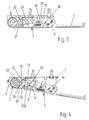
- FIGS. 1 and 2 show a ratchet tensioning device in its normal position.
- a base part 1 is fastened by means of several screws 1 a to a vehicle body.
- the base part 1 consists of a base plate 1 b and two right side walls 1 c. Pivoting with respect to a rotation axis A, a hand lever 2 is mounted on the base part 1, which has a handle 3 at its other end. Near the handle 3 is located in the hand lever an actuating button. 4
- the ratchet wheel 5 is extended out of the base part 1 out and there has a slot 6 or also serving as a drive polygon.
- the slot or polygon serves to wind there a windable object, such as a strap or a wind-up tarpaulin.
- the side walls 1 c are provided with holes in which the ratchet wheel 5 is mounted.
- the pivotal mounting of the hand lever 2 takes place.
- a bolt 10 mounted longitudinally movable. In this longitudinal direction of the latch 10 is acted upon by a voltage applied to the other hand on a surface of the hand lever 2 spring 11. The spring 11 pushes the latch 10 in the direction of the handle 3 or to the operation button 4 back.
- the actuating button 4 for the latch 10 is designed as a double-jointed button. It is connected via a hinge 12 pivotally connected to the bolt 10, at the same time is their other end, as above all Fig. 6 can recognize, led at 13 in the hand lever 2.
- the guide 13 is here a slot guide with an oblique arrangement of the slot.
- Fig. 7 shows in a second embodiment, an alternative operation of the bolt 10.
- the actuating button 4 is designed in this case as a rocker and its outer arm must, in order to move the bolt 10 against the force of the spring 11, are tightened in the direction R.
- On the other arm of the rocker is a cam 15 which slides on the surface 16 of the bolt 10 along and in this way the bolt 10 of the handle 3 drives away.
- the embodiment is after Fig. 7 designed as the first embodiment according to the FIGS. 1 to 6 ,
- Fig. 2 is located on the longitudinally guided bolt 10, a locking hook 18, which engages behind a locking element 19 formed on the base part 1 when the hand lever is locked.
- a locking hook 18 which engages behind a locking element 19 formed on the base part 1 when the hand lever is locked.
- the blocking surface 19 is a web, which is prepared by forming the corresponding portion of the base plate 1 b.
- the blocking surface 19 facing away from the locking hook 18 is provided with an insertion bevel 20. This has such a tendency and extension that, when the first opened hand lever 2 is pivoted back into the base part 1 back, the bolt is pushed back by the locking surface 19 and against the force of the spring 11, and then snaps behind the locking surface 19 , For closing the hand lever 2, it is therefore sufficient to simply press the hand lever 2 against the base part 1.
- a driving pawl 21 is pivotally mounted in the hand lever 2 on an axis A1. Also close to the ratchet wheel 5, a pawl 22 is pivotally mounted in the base part 1 on an axis A2.
- the axes A1, A2 are parallel to each other and parallel to the axis of rotation A of the ratchet wheel 5.
- the driving pawl 21 and the pawl 22 are each provided with a spring 23, which tends to the pawl projections 26, 27 (FIG. Fig. 4 ) against the teeth of the ratchet wheel 5. For clarity, only the spring 23 of the housing-fixed pawl 22 is shown in the drawing.
- the driving pawl 21 has an outer side 25 and the pawl projection 26, whose shape adapted in the manner of the tooth contour of the ratchet wheel 5, that the driving pawl 21 with the pawl projection 26, the ratchet wheel 5 in the direction of rotation D. can drive when the hand lever 2 according to Fig. 4 and Fig. 5 is pivoted.
- the engagement of the driving pawl 21 in the ratchet wheel 5 thus takes place when the hand lever 2 is pivoted outwardly from the base part 1.
- Fig. 4 shows how in this case the pawl projection 27 of the pawl 22 locks the ratchet wheel 5 against turning back against the direction of rotation D or blocks.
- the pawl 22 is rocker-shaped with two latch arms 22a, 22b designed. Near its pawl projection 27 is located on the pawl arm 22a of the pawl, a driver element 29, designed here as a corner contour. With a corresponding pivoting of the pawl 22, the driver element 29 abuts against the outside 25 of the driving pawl 21, whereby the pawl 22 entrains the driving pawl 21, and both pawls 21, 22 at the same time lose the engagement in the ratchet wheel 5. This function will now be explained in more detail.
- the Fig. 4 shows the hand lever 2 in a slightly open position, whereby the spring-loaded latch 10 sits by non-actuation of the actuating button 4 in its normal position. If, in this position, the bolt 10 is fully advanced in the direction R, then a projection 31 formed on the bolt 10 reaches below and behind a projection 32 which is formed on the pawl arm 22b of the pawl 22. The projection 31 is directed to the latch 10 to the base part 1, and the projection 32 on the pawl 22 to the hand lever 2 directed towards. In addition, the projection 32 is on that arm 22b of the rocker-shaped pawl 22, which faces away from the pawl projection 27 of the pawl 22.
- the bolt can be removed from its basic position ( Fig. 2 ) not into its freewheeling position ( Fig. 6 ) move.
- an end region 36 formed on the latch 10, on which the projection 31 is located abuts against the pawl 22 or against the projection 32 formed thereon from outside. This abutment is in FIG Fig. 3 shown. From the basic position to Fig. 2 can therefore be the latch 10 at most up to the Entriegel ein Fig. 3 move, and not to the freewheeling position Fig. 6 ,
- the driver element 29 of the ratchet arm 22a takes along the driving pawl 21, whereby it also rotates away from the ratchet wheel 5 and loses engagement in the ratchet wheel. In this way, the ratchet wheel 5 is free to move in the sense of a freewheel.
- the bolt is provided with a suitable pressure element 33.
- the pressure element 33 is here a surface on the bolt 10, against which the Kinkinkenarm 22 b abuts, whereby the pawl 22 pivots.
- FIGS. 8 and 9 a further embodiment of the ratchet assembly is shown. Again, this embodiment also has the ratchet wheel 5, the pawl 22 mounted on the axis A2 in the base part 1, the driving pawl 21 mounted on the hand lever 2 on the axis A1, and the latch 10 guided longitudinally displaceably in the hand lever 2
- the design of the formed on the bolt 10 pressure element 33 As a pressure element 33 serves here a ramp which passes during advancement of the bolt 10 under the rear arm of the rocker-shaped driving claw 21.
- the bolt 10 acts only indirectly on the pawl 22 to keep them out of engagement with the ratchet wheel 5.
- the driving pawl 21 takes the pawl 22 with.
- the ratchet wheel 5 remote from the pawl arm of the driving pawl 21 abuts against the pawl 22 b of the pawl 22.
- a projection 40 and on the ratchet arm 22 b of Pawl 22 a recess 41 is formed.
Landscapes
- Engineering & Computer Science (AREA)
- Transportation (AREA)
- Mechanical Engineering (AREA)
- Lock And Its Accessories (AREA)
- Devices For Conveying Motion By Means Of Endless Flexible Members (AREA)
- Transmission Devices (AREA)
Claims (15)
- Dispositif à rochet pour étirer des objets pouvant être enroulés, comprenant une partie de base (1) supportant en rotation une roue à rochet dentée (5), un levier manuel (2) monté de façon pivotante par rapport à la partie de base (1) sur le même axe de rotation (A) que la roue à rochet (5), un mécanisme à cliquets adapté à la denture de la roue à rochet (5) constitué d'un cliquet d'entraînement (21) sur le levier manuel (2) et d'un cliquet d'arrêt (22) sur la partie de base (1), et un verrou (10) monté sur le levier manuel (2) de façon à pouvoir être déplacé entre une position de base et au moins une position de déverrouillage qui verrouille le levier manuel (2) dans la position de base par liaison mécanique avec la partie de base (1) et le libère dans la position de déverrouillage,
caractérisé
en ce que le verrou (10) est réalisé de façon à pouvoir être déplacé, en plus de la positon de base et de déverrouillage, dans une position de roue libre dans laquelle un élément de pression (33) réalisé sur le verrou (10) maintient le cliquet d'arrêt (22) hors de prise dans la roue à rochet (5). - Dispositif à rochet selon la revendication 1, caractérisé en ce que dans la position de roue libre, l'élément de pression (33) du verrou (10) maintient également le cliquet d'entraînement (21) hors de prise dans la roue à rochet (5).
- Dispositif à rochet selon la revendication 1 ou 2, caractérisé en ce que dans la position de roue libre, l'élément de pression (33) appuie directement contre le cliquet d'arrêt (22) et maintient ainsi celui-ci hors de prise dans la roue à rochet (5).
- Dispositif à rochet selon la revendication 1 ou 2, caractérisé en ce que dans la position de roue libre, l'élément de pression (33) appuie contre le cliquet d'entraînement (21), qui peut pour sa part être déplacé en entraînant le cliquet d'arrêt (22) contre le cliquet d'arrêt (22), et maintient ainsi celui-ci hors de prise dans la roue à rochet (5).
- Dispositif à rochet selon l'une des revendications précédentes, caractérisé en ce que le cliquet d'arrêt (22) est monté de façon à pouvoir être déplacé par pivotement sur la partie de base (1), et le cliquet d'entraînement (21), de façon à pouvoir être déplacé par pivotement sur le levier manuel (2).
- Dispositif à rochet selon l'une des revendications précédentes, caractérisé par un élément de prise réalisé sur l'un des deux cliquets (22, 21), qui dans la position hors de prise de ce cliquet (22 ou 21), maintient également l'autre cliquet (21 ou 22) hors de prise dans la roue à rochet (5).
- Dispositif à rochet selon la revendication 6, caractérisé en ce que l'élément de prise (29) est un contour réalisé sur le cliquet d'arrêt (22), qui est adjacent à la saillie de cliquet (27) du cliquet d'arrêt (22) coopérant avec la denture de la roue à rochet (5).
- Dispositif à rochet selon l'une des revendications précédentes, caractérisé en ce que le verrou (10) est monté de façon à pouvoir être déplacé de façon longitudinale sur le levier manuel (2).
- Dispositif à rochet selon l'une des revendications précédentes, caractérisé par des moyens de limitation de course (32 ; 31, 36), qui lorsque le levier manuel (2) est fermé, bloquent un déplacement du verrou (10) vers sa position de roue libre.
- Dispositif à rochet selon la revendication 9, caractérisé en ce que les moyens de limitation de course sont constitués d'une butée (32) sur le cliquet d'arrêt (22) et d'une contre-butée (31, 36) sur le verrou (10).
- Dispositif à rochet selon l'une des revendications précédentes, caractérisé par des moyens de retenue (32, 31), qui lorsque le levier manuel (2) est fermé, bloquent le verrou (10) dans sa position de roue libre.
- Dispositif à rochet selon la revendication 11, caractérisé en ce que les moyens de retenue sont constitués de saillies (32, 31) sur le cliquet d'arrêt (22) et le verrou (10) qui se saisissent mutuellement par l'arrière dans le sens de déplacement du verrou (10).
- Dispositif à rochet selon l'une des revendications précédentes, caractérisé en ce que le verrou (10), pour verrouiller le levier manuel (2), est pourvu d'un crochet d'arrêt (18) qui saisit par l'arrière une surface d'arrêt (19) de la partie de base (1) et en ce que le crochet d'arrêt (18) est pourvu en opposition à la surface d'arrêt (19) d'un biseau d'introduction (20).
- Dispositif à rochet selon l'une des revendications précédentes, caractérisé par un bouton d'actionnement (4) pour le verrou (10) agencé dans le levier manuel (2) à proximité d'une poignée (3) réalisée sur celui-ci.
- Dispositif à rochet selon la revendication 14, caractérisé en ce que le bouton d'actionnement (4) est relié avec le verrou (10) de façon à pouvoir être déplacé par pivotement, et en même temps, guidé de façon longitudinale sur le levier manuel (2).
Applications Claiming Priority (1)
| Application Number | Priority Date | Filing Date | Title |
|---|---|---|---|
| DE200610044403 DE102006044403A1 (de) | 2006-09-18 | 2006-09-18 | Ratschenanordnung zum Spannen aufwickelbarer Gegenstände |
Publications (3)
| Publication Number | Publication Date |
|---|---|
| EP1900569A2 EP1900569A2 (fr) | 2008-03-19 |
| EP1900569A3 EP1900569A3 (fr) | 2013-06-12 |
| EP1900569B1 true EP1900569B1 (fr) | 2014-03-05 |
Family
ID=38729011
Family Applications (1)
| Application Number | Title | Priority Date | Filing Date |
|---|---|---|---|
| EP20070018283 Not-in-force EP1900569B1 (fr) | 2006-09-18 | 2007-09-18 | Dispositif à rochet pour étirer des objets pouvant être enroulés |
Country Status (3)
| Country | Link |
|---|---|
| EP (1) | EP1900569B1 (fr) |
| DE (1) | DE102006044403A1 (fr) |
| ES (1) | ES2451647T3 (fr) |
Families Citing this family (5)
| Publication number | Priority date | Publication date | Assignee | Title |
|---|---|---|---|---|
| FR2978391B1 (fr) * | 2011-07-28 | 2013-08-09 | Thiriet | Dispositif d'enroulement a commande manuelle d'un element enroulable, tel qu'une bache |
| DE202012100152U1 (de) | 2012-01-17 | 2012-02-24 | F. Hesterberg & Söhne Gmbh & Co. Kg | Ratschenanordnung zum Spannen aufwickelbarer Gegenstände |
| DE102013103684A1 (de) | 2013-04-12 | 2014-10-30 | F. Hesterberg & Söhne Gmbh & Co. Kg | Hebelanordnung zum Verschließen eines Nutzfahrzeug-Ladeaufbaus |
| FR3034057B1 (fr) | 2015-03-24 | 2017-03-10 | Thiriet | Dispositif d'enroulement a commande manuelle d'un element enroulable |
| US11406162B2 (en) * | 2020-11-11 | 2022-08-09 | Nite Ize, Inc. | Systems and methods for an improved ratcheting device including pivoting tooth |
Family Cites Families (11)
| Publication number | Priority date | Publication date | Assignee | Title |
|---|---|---|---|---|
| CH583089A5 (fr) * | 1975-04-30 | 1976-12-31 | Konrad Albert | |
| SE412557C (sv) * | 1978-04-28 | 1985-07-15 | Holmbergs Fab Ab Brdr | Bandstreckare |
| DE3240993C2 (de) * | 1981-11-06 | 1986-04-03 | Rud-Kettenfabrik Rieger & Dietz Gmbh U. Co, 7080 Aalen | Spannvorrichtung für Spannstränge, insbes. Gurte |
| DE3203750C2 (de) * | 1982-02-04 | 1986-07-24 | Edith 6901 Dossenheim Rutzki | Spannschloß für Gurtbänder |
| DE10004300A1 (de) * | 2000-02-01 | 2001-09-06 | Kranen Rolf | Vorrichtung zum lösbaren arretieren von Verriegelungen an Spannhebelelementen |
| FR2819501B1 (fr) * | 2001-01-15 | 2003-03-21 | Thiriet Fils | Dispositif d'enroulement a commande manuelle d'un element enroulable |
| CN2545095Y (zh) * | 2002-04-12 | 2003-04-16 | 宁波旭力金属制品有限公司 | 分步释放拉紧机机壳 |
| US6682053B1 (en) * | 2002-11-05 | 2004-01-27 | An-Chuan Chou | Winch of a lashing rope |
| DE10349229B4 (de) * | 2003-10-23 | 2013-05-29 | Wolfcraft Gmbh | Bandspanner und zugehörige Spannbacken |
| WO2006001714A1 (fr) * | 2004-06-25 | 2006-01-05 | Greyson Manufacturing Limited | Appareil tendeur |
| DE102004059339A1 (de) * | 2004-09-11 | 2006-03-16 | Pwp S.A., Payerne | Ratschenspannvorrichtung zum Spannen von Gegenständen wie Gurten und Planen |
-
2006
- 2006-09-18 DE DE200610044403 patent/DE102006044403A1/de not_active Withdrawn
-
2007
- 2007-09-18 EP EP20070018283 patent/EP1900569B1/fr not_active Not-in-force
- 2007-09-18 ES ES07018283T patent/ES2451647T3/es active Active
Also Published As
| Publication number | Publication date |
|---|---|
| DE102006044403A1 (de) | 2008-03-27 |
| ES2451647T3 (es) | 2014-03-28 |
| EP1900569A3 (fr) | 2013-06-12 |
| EP1900569A2 (fr) | 2008-03-19 |
Similar Documents
| Publication | Publication Date | Title |
|---|---|---|
| DE2603365C3 (de) | Verschluß für einen Kraftfahrzeugraum | |
| EP1536090B1 (fr) | Serrure pour véhicule | |
| WO2011070072A1 (fr) | Mécanisme de verrouillage pour un boîtier et serrure adaptée à ce mécanisme | |
| DE2403238A1 (de) | Tuerschloss | |
| DE4446460A1 (de) | Schloß zum unterstützten Schließen, insbesondere für eine Tür eines Automobils | |
| EP1900569B1 (fr) | Dispositif à rochet pour étirer des objets pouvant être enroulés | |
| EP2147175A1 (fr) | Serrure de portière de véhicule pouvant être actionnée de près et à distance | |
| DE102004002213B4 (de) | Fußgängerschutz-Aktuator mit Rückstelleinrichtung | |
| DE19933371A1 (de) | Schließeinrichtung mit Zuziehhilfe | |
| DE102005034833A1 (de) | Verschluß mit Ratschenklinke | |
| DE10019668A1 (de) | Schließvorrichtung, insbesondere für eine Kofferraumklappe | |
| EP1158126B1 (fr) | Serrure | |
| EP2843168A1 (fr) | Serrure de véhicule automobile | |
| DE4111646A1 (de) | Verriegelungseinrichtung, insbesondere fuer ein cabrio-faltverdeck | |
| DE3220705C2 (de) | Kraftfahrzeug-Türverschluß | |
| EP1642683B1 (fr) | Dispositif à cliquet pour la mise sous tension de sangles ou baches | |
| DE102017209376A1 (de) | Fahrzeugverschluss-Verriegelungsanordnung mit Doppelklinken-Verriegelungsmechanismus | |
| DE3935804A1 (de) | Kraftfahrzeug-haubenschloss oder -tuerschloss | |
| DE19821752A1 (de) | Verriegelungsvorrichtung für eine Kraftfahrzeugtür | |
| DE19806154C2 (de) | Kraftfahrzeugtürverschluß | |
| EP2617602B1 (fr) | Dispositif à rochet pour étirer des objets pouvant être enroulés | |
| EP0600228B1 (fr) | Dispositif pour ouvrir et fermer un couvercle de trou d'homme dans un véhicule de combat, en particulier un char | |
| EP0995866A2 (fr) | Serrure, notamment crémone serrure | |
| DE10042191A1 (de) | Kraftfahrzeug-Türschloß mit gesteuertem Stellelement | |
| EP0735220B1 (fr) | Serreure avec pêne réversible |
Legal Events
| Date | Code | Title | Description |
|---|---|---|---|
| PUAI | Public reference made under article 153(3) epc to a published international application that has entered the european phase |
Free format text: ORIGINAL CODE: 0009012 |
|
| AK | Designated contracting states |
Kind code of ref document: A2 Designated state(s): AT BE BG CH CY CZ DE DK EE ES FI FR GB GR HU IE IS IT LI LT LU LV MC MT NL PL PT RO SE SI SK TR |
|
| AX | Request for extension of the european patent |
Extension state: AL BA HR MK YU |
|
| PUAL | Search report despatched |
Free format text: ORIGINAL CODE: 0009013 |
|
| AK | Designated contracting states |
Kind code of ref document: A3 Designated state(s): AT BE BG CH CY CZ DE DK EE ES FI FR GB GR HU IE IS IT LI LT LU LV MC MT NL PL PT RO SE SI SK TR |
|
| AX | Request for extension of the european patent |
Extension state: AL BA HR MK RS |
|
| RIC1 | Information provided on ipc code assigned before grant |
Ipc: B60P 7/08 20060101AFI20130507BHEP |
|
| 17P | Request for examination filed |
Effective date: 20130822 |
|
| RBV | Designated contracting states (corrected) |
Designated state(s): AT BE BG CH CY CZ DE DK EE ES FI FR GB GR HU IE IS IT LI LT LU LV MC MT NL PL PT RO SE SI SK TR |
|
| GRAP | Despatch of communication of intention to grant a patent |
Free format text: ORIGINAL CODE: EPIDOSNIGR1 |
|
| INTG | Intention to grant announced |
Effective date: 20131031 |
|
| GRAS | Grant fee paid |
Free format text: ORIGINAL CODE: EPIDOSNIGR3 |
|
| GRAA | (expected) grant |
Free format text: ORIGINAL CODE: 0009210 |
|
| AKX | Designation fees paid |
Designated state(s): AT BE BG CH CY CZ DE DK EE ES FI FR GB GR HU IE IS IT LI LT LU LV MC MT NL PL PT RO SE SI SK TR |
|
| AK | Designated contracting states |
Kind code of ref document: B1 Designated state(s): AT BE BG CH CY CZ DE DK EE ES FI FR GB GR HU IE IS IT LI LT LU LV MC MT NL PL PT RO SE SI SK TR |
|
| REG | Reference to a national code |
Ref country code: GB Ref legal event code: FG4D Free format text: NOT ENGLISH |
|
| REG | Reference to a national code |
Ref country code: CH Ref legal event code: EP |
|
| REG | Reference to a national code |
Ref country code: AT Ref legal event code: REF Ref document number: 654620 Country of ref document: AT Kind code of ref document: T Effective date: 20140315 |
|
| REG | Reference to a national code |
Ref country code: ES Ref legal event code: FG2A Ref document number: 2451647 Country of ref document: ES Kind code of ref document: T3 Effective date: 20140328 |
|
| REG | Reference to a national code |
Ref country code: IE Ref legal event code: FG4D Free format text: LANGUAGE OF EP DOCUMENT: GERMAN |
|
| REG | Reference to a national code |
Ref country code: DE Ref legal event code: R096 Ref document number: 502007012807 Country of ref document: DE Effective date: 20140417 |
|
| REG | Reference to a national code |
Ref country code: NL Ref legal event code: VDEP Effective date: 20140305 |
|
| PG25 | Lapsed in a contracting state [announced via postgrant information from national office to epo] |
Ref country code: LT Free format text: LAPSE BECAUSE OF FAILURE TO SUBMIT A TRANSLATION OF THE DESCRIPTION OR TO PAY THE FEE WITHIN THE PRESCRIBED TIME-LIMIT Effective date: 20140305 |
|
| REG | Reference to a national code |
Ref country code: LT Ref legal event code: MG4D |
|
| PG25 | Lapsed in a contracting state [announced via postgrant information from national office to epo] |
Ref country code: SE Free format text: LAPSE BECAUSE OF FAILURE TO SUBMIT A TRANSLATION OF THE DESCRIPTION OR TO PAY THE FEE WITHIN THE PRESCRIBED TIME-LIMIT Effective date: 20140305 Ref country code: CY Free format text: LAPSE BECAUSE OF FAILURE TO SUBMIT A TRANSLATION OF THE DESCRIPTION OR TO PAY THE FEE WITHIN THE PRESCRIBED TIME-LIMIT Effective date: 20140305 Ref country code: FI Free format text: LAPSE BECAUSE OF FAILURE TO SUBMIT A TRANSLATION OF THE DESCRIPTION OR TO PAY THE FEE WITHIN THE PRESCRIBED TIME-LIMIT Effective date: 20140305 |
|
| PG25 | Lapsed in a contracting state [announced via postgrant information from national office to epo] |
Ref country code: LV Free format text: LAPSE BECAUSE OF FAILURE TO SUBMIT A TRANSLATION OF THE DESCRIPTION OR TO PAY THE FEE WITHIN THE PRESCRIBED TIME-LIMIT Effective date: 20140305 |
|
| PG25 | Lapsed in a contracting state [announced via postgrant information from national office to epo] |
Ref country code: RO Free format text: LAPSE BECAUSE OF FAILURE TO SUBMIT A TRANSLATION OF THE DESCRIPTION OR TO PAY THE FEE WITHIN THE PRESCRIBED TIME-LIMIT Effective date: 20140305 Ref country code: BG Free format text: LAPSE BECAUSE OF FAILURE TO SUBMIT A TRANSLATION OF THE DESCRIPTION OR TO PAY THE FEE WITHIN THE PRESCRIBED TIME-LIMIT Effective date: 20140605 Ref country code: EE Free format text: LAPSE BECAUSE OF FAILURE TO SUBMIT A TRANSLATION OF THE DESCRIPTION OR TO PAY THE FEE WITHIN THE PRESCRIBED TIME-LIMIT Effective date: 20140305 Ref country code: IS Free format text: LAPSE BECAUSE OF FAILURE TO SUBMIT A TRANSLATION OF THE DESCRIPTION OR TO PAY THE FEE WITHIN THE PRESCRIBED TIME-LIMIT Effective date: 20140705 Ref country code: CZ Free format text: LAPSE BECAUSE OF FAILURE TO SUBMIT A TRANSLATION OF THE DESCRIPTION OR TO PAY THE FEE WITHIN THE PRESCRIBED TIME-LIMIT Effective date: 20140305 Ref country code: NL Free format text: LAPSE BECAUSE OF FAILURE TO SUBMIT A TRANSLATION OF THE DESCRIPTION OR TO PAY THE FEE WITHIN THE PRESCRIBED TIME-LIMIT Effective date: 20140305 |
|
| PG25 | Lapsed in a contracting state [announced via postgrant information from national office to epo] |
Ref country code: SK Free format text: LAPSE BECAUSE OF FAILURE TO SUBMIT A TRANSLATION OF THE DESCRIPTION OR TO PAY THE FEE WITHIN THE PRESCRIBED TIME-LIMIT Effective date: 20140305 Ref country code: PL Free format text: LAPSE BECAUSE OF FAILURE TO SUBMIT A TRANSLATION OF THE DESCRIPTION OR TO PAY THE FEE WITHIN THE PRESCRIBED TIME-LIMIT Effective date: 20140305 |
|
| REG | Reference to a national code |
Ref country code: DE Ref legal event code: R097 Ref document number: 502007012807 Country of ref document: DE |
|
| REG | Reference to a national code |
Ref country code: DE Ref legal event code: R082 Ref document number: 502007012807 Country of ref document: DE Representative=s name: BUNGARTZ CHRISTOPHERSEN PARTNERSCHAFT MBB PATE, DE |
|
| PG25 | Lapsed in a contracting state [announced via postgrant information from national office to epo] |
Ref country code: PT Free format text: LAPSE BECAUSE OF FAILURE TO SUBMIT A TRANSLATION OF THE DESCRIPTION OR TO PAY THE FEE WITHIN THE PRESCRIBED TIME-LIMIT Effective date: 20140707 |
|
| PLBE | No opposition filed within time limit |
Free format text: ORIGINAL CODE: 0009261 |
|
| STAA | Information on the status of an ep patent application or granted ep patent |
Free format text: STATUS: NO OPPOSITION FILED WITHIN TIME LIMIT |
|
| PG25 | Lapsed in a contracting state [announced via postgrant information from national office to epo] |
Ref country code: DK Free format text: LAPSE BECAUSE OF FAILURE TO SUBMIT A TRANSLATION OF THE DESCRIPTION OR TO PAY THE FEE WITHIN THE PRESCRIBED TIME-LIMIT Effective date: 20140305 |
|
| 26N | No opposition filed |
Effective date: 20141208 |
|
| REG | Reference to a national code |
Ref country code: DE Ref legal event code: R097 Ref document number: 502007012807 Country of ref document: DE Effective date: 20141208 |
|
| PG25 | Lapsed in a contracting state [announced via postgrant information from national office to epo] |
Ref country code: LU Free format text: LAPSE BECAUSE OF FAILURE TO SUBMIT A TRANSLATION OF THE DESCRIPTION OR TO PAY THE FEE WITHIN THE PRESCRIBED TIME-LIMIT Effective date: 20140918 Ref country code: MC Free format text: LAPSE BECAUSE OF FAILURE TO SUBMIT A TRANSLATION OF THE DESCRIPTION OR TO PAY THE FEE WITHIN THE PRESCRIBED TIME-LIMIT Effective date: 20140305 |
|
| PG25 | Lapsed in a contracting state [announced via postgrant information from national office to epo] |
Ref country code: SI Free format text: LAPSE BECAUSE OF FAILURE TO SUBMIT A TRANSLATION OF THE DESCRIPTION OR TO PAY THE FEE WITHIN THE PRESCRIBED TIME-LIMIT Effective date: 20140305 |
|
| REG | Reference to a national code |
Ref country code: IE Ref legal event code: MM4A |
|
| PG25 | Lapsed in a contracting state [announced via postgrant information from national office to epo] |
Ref country code: BE Free format text: LAPSE BECAUSE OF NON-PAYMENT OF DUE FEES Effective date: 20140930 |
|
| PG25 | Lapsed in a contracting state [announced via postgrant information from national office to epo] |
Ref country code: IE Free format text: LAPSE BECAUSE OF NON-PAYMENT OF DUE FEES Effective date: 20140918 |
|
| REG | Reference to a national code |
Ref country code: AT Ref legal event code: MM01 Ref document number: 654620 Country of ref document: AT Kind code of ref document: T Effective date: 20140918 |
|
| PG25 | Lapsed in a contracting state [announced via postgrant information from national office to epo] |
Ref country code: AT Free format text: LAPSE BECAUSE OF NON-PAYMENT OF DUE FEES Effective date: 20140918 |
|
| PG25 | Lapsed in a contracting state [announced via postgrant information from national office to epo] |
Ref country code: GR Free format text: LAPSE BECAUSE OF FAILURE TO SUBMIT A TRANSLATION OF THE DESCRIPTION OR TO PAY THE FEE WITHIN THE PRESCRIBED TIME-LIMIT Effective date: 20140606 Ref country code: MT Free format text: LAPSE BECAUSE OF FAILURE TO SUBMIT A TRANSLATION OF THE DESCRIPTION OR TO PAY THE FEE WITHIN THE PRESCRIBED TIME-LIMIT Effective date: 20140305 |
|
| PG25 | Lapsed in a contracting state [announced via postgrant information from national office to epo] |
Ref country code: HU Free format text: LAPSE BECAUSE OF FAILURE TO SUBMIT A TRANSLATION OF THE DESCRIPTION OR TO PAY THE FEE WITHIN THE PRESCRIBED TIME-LIMIT; INVALID AB INITIO Effective date: 20070918 |
|
| REG | Reference to a national code |
Ref country code: FR Ref legal event code: PLFP Year of fee payment: 10 |
|
| PGFP | Annual fee paid to national office [announced via postgrant information from national office to epo] |
Ref country code: CH Payment date: 20160926 Year of fee payment: 10 Ref country code: GB Payment date: 20160921 Year of fee payment: 10 |
|
| PGFP | Annual fee paid to national office [announced via postgrant information from national office to epo] |
Ref country code: FR Payment date: 20160922 Year of fee payment: 10 |
|
| PGFP | Annual fee paid to national office [announced via postgrant information from national office to epo] |
Ref country code: ES Payment date: 20160923 Year of fee payment: 10 Ref country code: TR Payment date: 20160907 Year of fee payment: 10 |
|
| PGFP | Annual fee paid to national office [announced via postgrant information from national office to epo] |
Ref country code: DE Payment date: 20160930 Year of fee payment: 10 |
|
| PGFP | Annual fee paid to national office [announced via postgrant information from national office to epo] |
Ref country code: IT Payment date: 20160922 Year of fee payment: 10 |
|
| REG | Reference to a national code |
Ref country code: DE Ref legal event code: R119 Ref document number: 502007012807 Country of ref document: DE |
|
| REG | Reference to a national code |
Ref country code: CH Ref legal event code: PL |
|
| GBPC | Gb: european patent ceased through non-payment of renewal fee |
Effective date: 20170918 |
|
| REG | Reference to a national code |
Ref country code: FR Ref legal event code: ST Effective date: 20180531 |
|
| PG25 | Lapsed in a contracting state [announced via postgrant information from national office to epo] |
Ref country code: LI Free format text: LAPSE BECAUSE OF NON-PAYMENT OF DUE FEES Effective date: 20170930 Ref country code: DE Free format text: LAPSE BECAUSE OF NON-PAYMENT OF DUE FEES Effective date: 20180404 Ref country code: GB Free format text: LAPSE BECAUSE OF NON-PAYMENT OF DUE FEES Effective date: 20170918 Ref country code: CH Free format text: LAPSE BECAUSE OF NON-PAYMENT OF DUE FEES Effective date: 20170930 |
|
| PG25 | Lapsed in a contracting state [announced via postgrant information from national office to epo] |
Ref country code: IT Free format text: LAPSE BECAUSE OF NON-PAYMENT OF DUE FEES Effective date: 20170918 Ref country code: FR Free format text: LAPSE BECAUSE OF NON-PAYMENT OF DUE FEES Effective date: 20171002 |
|
| REG | Reference to a national code |
Ref country code: ES Ref legal event code: FD2A Effective date: 20181019 |
|
| PG25 | Lapsed in a contracting state [announced via postgrant information from national office to epo] |
Ref country code: ES Free format text: LAPSE BECAUSE OF NON-PAYMENT OF DUE FEES Effective date: 20170919 |
|
| PG25 | Lapsed in a contracting state [announced via postgrant information from national office to epo] |
Ref country code: TR Free format text: LAPSE BECAUSE OF NON-PAYMENT OF DUE FEES Effective date: 20170918 |