EP1900654B1 - Automate de réception des marchandises - Google Patents
Automate de réception des marchandises Download PDFInfo
- Publication number
- EP1900654B1 EP1900654B1 EP07114704A EP07114704A EP1900654B1 EP 1900654 B1 EP1900654 B1 EP 1900654B1 EP 07114704 A EP07114704 A EP 07114704A EP 07114704 A EP07114704 A EP 07114704A EP 1900654 B1 EP1900654 B1 EP 1900654B1
- Authority
- EP
- European Patent Office
- Prior art keywords
- package
- goods receiving
- receiving device
- automatic goods
- packages
- Prior art date
- Legal status (The legal status is an assumption and is not a legal conclusion. Google has not performed a legal analysis and makes no representation as to the accuracy of the status listed.)
- Not-in-force
Links
- 238000012546 transfer Methods 0.000 claims description 25
- 239000002699 waste material Substances 0.000 claims description 9
- 230000004044 response Effects 0.000 claims description 2
- 230000003247 decreasing effect Effects 0.000 claims 1
- 230000005484 gravity Effects 0.000 claims 1
- 238000012856 packing Methods 0.000 abstract description 6
- 230000032258 transport Effects 0.000 description 28
- 230000002093 peripheral effect Effects 0.000 description 8
- 238000000926 separation method Methods 0.000 description 4
- 229940079593 drug Drugs 0.000 description 3
- 239000003814 drug Substances 0.000 description 3
- 230000008901 benefit Effects 0.000 description 2
- 230000000694 effects Effects 0.000 description 2
- 241000446313 Lamella Species 0.000 description 1
- 238000013019 agitation Methods 0.000 description 1
- 238000013461 design Methods 0.000 description 1
- 238000011161 development Methods 0.000 description 1
- 230000003993 interaction Effects 0.000 description 1
- 239000011159 matrix material Substances 0.000 description 1
- 238000002483 medication Methods 0.000 description 1
- 239000002184 metal Substances 0.000 description 1
- 238000012545 processing Methods 0.000 description 1
- 230000000284 resting effect Effects 0.000 description 1
- 230000007704 transition Effects 0.000 description 1
Images






Classifications
-
- B—PERFORMING OPERATIONS; TRANSPORTING
- B65—CONVEYING; PACKING; STORING; HANDLING THIN OR FILAMENTARY MATERIAL
- B65G—TRANSPORT OR STORAGE DEVICES, e.g. CONVEYORS FOR LOADING OR TIPPING, SHOP CONVEYOR SYSTEMS OR PNEUMATIC TUBE CONVEYORS
- B65G1/00—Storing articles, individually or in orderly arrangement, in warehouses or magazines
- B65G1/02—Storage devices
- B65G1/04—Storage devices mechanical
- B65G1/0407—Storage devices mechanical using stacker cranes
-
- B—PERFORMING OPERATIONS; TRANSPORTING
- B65—CONVEYING; PACKING; STORING; HANDLING THIN OR FILAMENTARY MATERIAL
- B65G—TRANSPORT OR STORAGE DEVICES, e.g. CONVEYORS FOR LOADING OR TIPPING, SHOP CONVEYOR SYSTEMS OR PNEUMATIC TUBE CONVEYORS
- B65G1/00—Storing articles, individually or in orderly arrangement, in warehouses or magazines
- B65G1/02—Storage devices
- B65G1/04—Storage devices mechanical
-
- B—PERFORMING OPERATIONS; TRANSPORTING
- B65—CONVEYING; PACKING; STORING; HANDLING THIN OR FILAMENTARY MATERIAL
- B65G—TRANSPORT OR STORAGE DEVICES, e.g. CONVEYORS FOR LOADING OR TIPPING, SHOP CONVEYOR SYSTEMS OR PNEUMATIC TUBE CONVEYORS
- B65G1/00—Storing articles, individually or in orderly arrangement, in warehouses or magazines
- B65G1/02—Storage devices
- B65G1/04—Storage devices mechanical
- B65G1/0485—Check-in, check-out devices
-
- B—PERFORMING OPERATIONS; TRANSPORTING
- B65—CONVEYING; PACKING; STORING; HANDLING THIN OR FILAMENTARY MATERIAL
- B65G—TRANSPORT OR STORAGE DEVICES, e.g. CONVEYORS FOR LOADING OR TIPPING, SHOP CONVEYOR SYSTEMS OR PNEUMATIC TUBE CONVEYORS
- B65G11/00—Chutes
- B65G11/06—Chutes of helical or spiral form
- B65G11/063—Chutes of helical or spiral form for articles
-
- B—PERFORMING OPERATIONS; TRANSPORTING
- B65—CONVEYING; PACKING; STORING; HANDLING THIN OR FILAMENTARY MATERIAL
- B65G—TRANSPORT OR STORAGE DEVICES, e.g. CONVEYORS FOR LOADING OR TIPPING, SHOP CONVEYOR SYSTEMS OR PNEUMATIC TUBE CONVEYORS
- B65G2201/00—Indexing codes relating to handling devices, e.g. conveyors, characterised by the type of product or load being conveyed or handled
- B65G2201/02—Articles
- B65G2201/027—Tablets, capsules, pills or the like
Definitions
- the invention relates to an automatic goods receiving machine, in particular for storing packages in an automatic warehouse, which has numerous storage locations and a bearing manipulator transporting the packages, with an outgoing from an input hopper transport device.
- EP 1 407 984 B1 discloses a goods receiving machine according to the preamble of claim 1 and describes a shelf storage with drawing shelves.
- the shelf storage is used to hold packages that may contain medications, for example.
- the shelf storage includes a transport device, which is along a corridor, on both sides of which Ziehregale located, is movable.
- the transport device carries a manipulator capable of removing the packages from one of the drawing shelves and transporting them to a receiving device, which is followed by a conveyor belt.
- the Packs manually inserted into the goods transfer rack, grabbed by the manipulator and transported to a storage location.
- EP 0 620 528 B2 (Schausten ) describes an automatic goods receiving device with automatic separation and pre-sorting of entered packages. A barcode attached to the packages is read by a scanner to identify the package.
- the invention has for its object to provide a pick-and-place machine for storing packages in an automatic warehouse, which brings the packs in a defined position with simple technical means.
- the goods receiving machine of the present invention is defined by claim 1. After that, the transport device leads to a spiral chute, on which an alignment of the packs takes place and behind which a selection device is provided.
- the invention enables the unordered feeding of packages of different formats and sizes with subsequent separation and alignment, so that an automatic identification can take place.
- the spiral chute forms a suitable element for bringing parallelepipedic packings into an appropriate orientation.
- the packs are pressed against the peripheral wall, where they overlap one major surface invest. If a package passes transversely to the spiral chute, it is at the end, which faces the longitudinal axis of the spiral chute, because of the larger slope there, accelerated downwards accelerated so that the package undergoes a rotation and then against one of its longitudinal sides against the peripheral wall of the spiral chute sets.
- the spiral chute also has the effect that the packs preferably lie with their broad side on the bottom of the spiral chute and not upright go through the spiral chute.
- the spiral chute is therefore a suitable means for bringing the packs in a defined orientation, namely with broadside resting on the bottom, one front side of the pack pointing to the front and the other front side to the rear.
- the selection device discards those packages which are unsuitable for storage in a waste basket, while it releases the other packages for transfer to the automatic warehouse.
- a coarse separation of the packages is possible by the interaction of the transport device and the spiral chute.
- the transport device is driven in such a way that it conveys a package up to a delivery point and only carries out a conveying step beyond when a sensor at the foot of the spiral chute does not detect any packing.
- the packages may initially be conveyed in an arbitrary arrangement and order. If said sensor determines that there is no packing, the transport device is caused to perform a defined conveying step whereby the front package is transferred to and slides down the spiral chute. As long as the sensor detects a package, no further drive of the transport device takes place. The sensor indicates that no Pack is more present, the transport device is put back into operation until a front pack is transferred to the spiral chute.
- the spiral chute has a chute bottom with fold lines, the kink lines separating surfaces with different slopes from each other.
- a descending packing is pulsed, thereby improving the alignment effect.
- the package is prevented from sticking to the bottom of the chute without turning into the correct position adjacent to the side wall of the chute.
- a controlled stopper For separating the packs, a controlled stopper can be provided, which separates successive packs from one another.
- a surveying station is provided with a first sensor for measuring the height and a second sensor for measuring the width of the pack.
- An ejector redirects the package to the transport device when the measured height is greater than the measured width. In this way it is avoided that a package is transferred in the wrong orientation to the warehouse. A pack that is in the wrong orientation is returned to the conveyor and passes through the spiral chute a second time.
- packages whose identification can not be read by machine are transported to a waste basket.
- a grab accessing the packs may be provided, which deposits the packs in a collection compartment.
- the warehouse manipulator can pick up the packages individually and transfer them to the rack warehouse.
- FIG. 1 shows an automatic warehouse 10, which has numerous Ziehregale that can be driven under the control of a computer in a central corridor 11.
- FIG. 1 are the drawing galleries not shown, however the rails 12 in which they are guided. These rails run across the aisle.
- the Ziehregallager is formed in the same way as that of EP 1 407 984 B1 ,
- the warehouse 10 is divided into individual modules 13, which have a rectangular plan. Some of the modules 13 contain the drawbars and others form the aisle 11.
- the goods receiving machine 14 is located on the front side of the warehouse 10, which forms the feed side and here at the same time the goods issue page.
- the goods receiving machine 14 includes an arranged in front of the housing of the warehouse 10 input point 20, which is here a funnel, in which the existing of individual packages contents of a goods container can be randomly poured into it.
- the warehouse with the goods receipt machine is typically a pharmacy warehouse in which medicines and other pharmacy products, packaged in boxes, are stored. For storage, the delivered packages, which are unsorted, are filled manually into the hopper.
- a transport device 21 which in the present case has a conveyor belt 22 with transverse lugs 23, leads to a delivery point 24, which is located at the upper end of the transport device 21.
- the transport device 21 is here a steep conveyor, at the lower end of the input point 20 is located.
- To the input point 20 also leads a return conveyor 25, which leads out of the goods receiving machine 14 and packages that had an incorrect orientation, returns to the input point, so that they pass through the transport device 21 again.
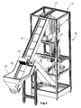
- FIG. 2 shows the skeleton of the module 13, in which the goods receiving machine is housed.
- the transport device 21 leads into it.
- a downward spiral chute 26 connects, which runs around a vertical column 27 helically and extends from the delivery point 24 to a lower Verresssstation 29 ( FIG. 5 ).
- a scraper 28 in the form of a rotating brush is arranged above the conveyor belt 22.
- the scraper 28 prevents two packages from completely or partially overlapping each other. In the case of an overlay, he strips the upper pack from the lower pack, so that both come to lie on the conveyor belt next to each other or behind each other.
- the helical chute extends more than one turn around the pillar 27 mounted in a frame 30.
- the spiral chute 26 has a helical bottom 31 and a peripheral wall 32 bounding the bottom radially outward. The design of the bottom 31 will be explained later in more detail.
- the surveying station 29 At the lower end of the spiral chute 26 is the surveying station 29 ( FIG. 6 ). This has a transversely almost horizontal plate, which follows in the longitudinal direction of the slope of the spiral chute. Through a slot of this plate extends a stopper 33, against which a spiral chute sliding down pack. In the oblique plate of the surveying station 29 are openings 38 through which a plurality of prongs of an auxiliary stopper 39 can be inserted through from below. As the stopper 33 is lowered and the auxiliary stopper 39 is raised, the package slides over the tines of the auxiliary stopper from the surveying station 29 to the transfer station 40. The next succeeding package is stopped by the auxiliary stopper 39 and prevented from following the first package.
- the auxiliary stopper 39 is only lowered after the stopper 33 is raised.
- the package then slides against the stopper 33.
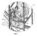
- the surveying station 29 measures the height and width of the package and determines whether the height of the package lying is greater than the width. The determination of whether the package is "higher than wide” is made by means of a sensor 43 which detects the package height and a sensor 44 which determines the package width ( FIG. 7 ).
- the sensors 43 and 44 are ultrasonic sensors, which are arranged at the surveying station 29 and determine without contact the relevant dimension of the pack.
- an ejector 35 is activated, which transfers the pack to the return conveyor 25.
- the provided in the transition to the surveying station 29 sensor 34 is used to control the transport device 21.
- the sensor 34 prevents the transport device 21 is set in motion, if he still notes the presence of a pack.
- the transport device 21 is driven until a package reaches the delivery point 24 at the upper end of the transport device. This is determined by an upper sensor provided there. If there is no package on the sensor 34, then the transport device continues to run for a short distance before being shut down. The package that caused the triggering of the upper sensor then falls onto the spiral chute and slides down on it.
- This control of the transport device causes a certain pre-separation. There are several packs on the spiral chute, but it can not happen that the entire spiral chute is full of packs. Ideally, a maximum of one pack slides down the spiral chute at any one time.
- the transfer station 40 Behind the surveying station 29 is a transfer station 40.
- the transfer station 40 has a slightly inclined in the transverse direction plate, a one-sided contact plate 41 and a stop 42.
- the transfer station 40 can be pivoted about a horizontal transverse axis.
- the Transfer station 40 is inclined according to the slope of the surveying station 29 when the package from the surveying station 29 on the transfer station 40 against the stop 42 slips. Thereafter, the transfer station is pivoted about the horizontal transverse axis in the illustrated horizontal gripping position.
- a pack, which lies on the transfer station 40 and has met the criteria required by the surveying device is gripped by a gripper 45, which is designed here as a suction pad with a plurality of controlled Saugnäpfen.
- the gripper 45 is located at the end of a pivot arm 46 which is pivotable about a horizontal axis 47 controlled between the transfer station 40 and a pick-up tray 55.
- On the pivot arm 46 of the gripper 45 is movable in height.
- a pneumatic cylinder 48a is provided on the pivoting.
- the pivoting is effected by a further pneumatic cylinder 48b, which is supported on a plate 49 fixed to the frame.
- the plate 49 also carries a scanner 50 for scanning an identification on the package, e.g. As a bar code reader or a data matrix reader.
- the scanner 50 is arranged to scan the upper broad side and the exposed narrow side of a package located in the transfer station 40 and recognize a barcode present on these pages.
- Another scanner 51 is located near the collection compartment 55. This scanner detects the package as it hangs on the gripper 45 and pivots in front of the scanner. It detects those sides of the package that were obscured by walls in the transfer station 40 and the faces of the package.
- a pack on which an identification has been recognized is deposited by the gripper 45 in the pick-up tray 55.
- This is attached to a pendulum arm 54 of a pneumatic cylinder 52 between a receiving position and a Pick-up position is pivotable. In the pick-up position, the package can be picked up by a manipulator of the automatic warehouse.
- ejector 56 in the form of a lever which is pivotable about an axis 57 and passes through a slot 58 in the abutment plate 41 to drop a package from the transfer station 40 into the waste basket 37 inside. If the package exceeds the predetermined maximum dimensions, so that it does not fit into a warehouse of the warehouse, it is ejected in the transfer station. This is done by the ejector 56, which penetrates through an opening in the side wall and pushes down the pack, so that it falls into a waste basket 37 ( FIG. 7 ).
- the ejector 56 is part of a selection device 53 for selecting not for the storage of suitable packages. It is activated when an identification on the package could not be detected or read.
- the pack is first covered by the gripper 45 to the transfer station 40 and then dropped from there into the waste basket 37.
- the ejector 56 is also actuated when it is determined by a sensor 59 provided at the transfer station 40 that the packing present in the transfer station at a front stop is "too long", ie that its length exceeds a limit, so that storage does not occur is possible. If this is the case, an ejection of the pack into the waste basket 37 takes place by actuating the ejector 56.
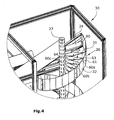
- the bottom 31 of the spiral chute 26 is according to FIG. 4 from individual blades 60, which are each made together with a peripheral part 61 in one piece from sheet metal.
- the peripheral parts 61 of a plurality of fins are integrally connected to each other.
- Each sipe 60 is from the peripheral part 61 to the column 27 out.
- the fin 60 has an outer first region 60a, a middle second region 60b and an inner region 60c.
- the three areas are connected by crease lines 63, 64.
- the first area 60a has the lowest pitch
- the second area 60b has a larger pitch
- the inner area 60c the largest slope.
- FIG. 8 shows a section of the spiral chute in the unwound state.
- the peripheral part 61 and the protruding therefrom lamella 60 can be seen.
- sections 60a, 60b and 60c have increasing slopes in this order.
- the louvers are each provided with a tab 65 with hole 66 which engages a hole 67 of an adjacent louver to form a substantially continuous chute bottom.
- the control of the goods receiving machine 14 is carried out by the computer of the warehouse, which also controls the manipulator of the warehouse and performs the storage and retrieval of packages. If the control computer of the warehouse gives a command to issue a good, the putaway is interrupted. In this case, the goods issue has priority. After completion of the goods issue of the warehouse manipulator for the receipt of goods from the automatic teller 14 is available.
- FIG. 9 an alternative embodiment of the reading device for reading the identification on the package is shown, with a modified structure of the transfer station 40th
- the spiral chute 26 is the same as in the first embodiment and this surveying chute is followed by first the surveying station 29 with the stopper 33 and the ejector 35 connects.
- the reading device 70 On the Downslope behind the surveying station 29, the reading device 70 is provided. This is a loop surrounding the transport path that contains a radio-frequency antenna.
- the reading device 70 is used to read from a tag or chip on the package contactless identification.
- the tag or chip is a transponder which reads out its contents in response to an external request signal.
- This system is known as an RFID system (Radio Frequency Identification). It has the advantage that the pack does not have to be brought into a specific position with respect to the reading device, as when reading a barcode. Another advantage is that in the RFID system considerably more data can be stored and retrieved than in the usual barcode system. So it is possible, for example, save the identification of the drug in question, the expiration date, the batch number or other data and output on query.
- the reading device 70 is arranged at the inlet end of the retrieval tray 55, which by the pendulum arm 54 of the in FIG. 9 represented receiving position about the pivot axis 71 can be pivoted transversely to the transport direction in a (not shown) pickup position in which the manipulator of the automatic warehouse can access the pack 72.
- the retrieval compartment 55 is pivoted down about an axis 73 transverse to the conveying path so that the package 72 is thrown into the waste basket.
Landscapes
- Engineering & Computer Science (AREA)
- Mechanical Engineering (AREA)
- Warehouses Or Storage Devices (AREA)
- Vending Machines For Individual Products (AREA)
- Chutes (AREA)
Claims (14)
- Automate de réception des marchandises, particulièrement pour stocker des paquets dans un dépôt automatique (10) avec plusieurs endroits de stockage et un manipulateur du dépôt transportant les paquets, comprenant un dispositif de transport (21) s'étendant d'un endroit d'introduction (20),
caractérisé en ce que
le dispositif de transport (21) mène à une chute en hélice (26) sur laquelle les paquets sont alignés et après laquelle est prévu un dispositif de sélection (53). - Automate de réception des marchandises selon la revendication 1, caractérisé en ce que le dispositif de transport (21) est entraîné de manière à ce qu'il transporte un paquet jusqu'à un endroit de distribution (24) et fasse un mouvement de transport au-delà de cet endroit seulement si un capteur (34) ne détecte pas un paquet dans la zone d'extrémité basse de la chute en hélice (26).
- Automate de réception des marchandises selon la revendication 1 ou 2, caractérisé en ce que la chute en hélice (26) comprend un fond de chute (31) avec des lignes de pli (63, 64), les lignes de pli délimitant des surfaces de différentes pentes.
- Automate de réception des marchandises selon la revendication 3, caractérisé en ce que la pente des surfaces (60a, 60b, 60c) décroît avec la croissance de l'écart de l'axe longitudinal vertical de la chute en hélice.
- Automate de réception des marchandises selon l'une quelconque des revendications 1-4, caractérisé en ce que le dispositif de transport (21) est une bande de transport (22) munie de nervures (23).
- Automate de réception des marchandises selon l'une quelconque des revendications 1-5, caractérisé en ce que le dispositif de transport (21) comprend une racle (28) pour éliminer des superpositions de paquets.
- Automate de réception des marchandises selon l'une quelconque des revendications 1-6, caractérisé en ce qu'une butée commandée (33) est prévue à l'extrémité basse de la chute en hélice, la butée séparant des paquets positionnés l'un derrière l'autre.
- Automate de réception des marchandises selon l'une quelconque des revendications 1-7, caractérisé en ce que une station de mesurage (29) est prévue, comprenant un premier capteur (43) pour mesurer la hauteur et un deuxième capteur (44) pour mesurer la largeur d'un paquet, et qu'un éjecteur (35) retourne le paquet sur ledit dispositif de transport (21) quand la hauteur mesurée est plus grande que la largeur mesurée.
- Automate de réception des marchandises selon l'une quelconque des revendications 1-8, caractérisé en ce qu'une griffe (45) prenant les paquets est prévue en une station de transfert (40), la griffe pouvant déposer les paquets dans un compartiment de récupération (55).
- Automate de réception des marchandises selon l'une quelconque des revendications 1-9, caractérisé en ce qu'au moins un dispositif de lecture (50, 51) est prévu pour lire une identification sur le paquet, et qu'un paquet, dont l'identification était lue avec succès, est disposé dans un compartiment de récupération (55) auquel peut accéder le manipulateur du dépôt.
- Automate de réception des marchandises selon la revendication 10, caractérisé en ce qu'un éjecteur (56) est prévu qui fait tomber le paquet dans un réservoir des déchets (37), en cas aucune identification peut être lue.
- Automate de réception des marchandises selon l'une quelconque des revendications 1-11, caractérisé en ce que le dispositif de transport (21) et la chute en hélice (26) sont inclus dans un module (13) correspondant aux modules du dépôt automatique (10).
- Automate de réception des marchandises selon l'une quelconque des revendications 1-12, caractérisé en ce qu'au moins un dispositif de lecture (70) est prévu pour lire une identification sur un paquet (72), et que le dispositif de lecture comprend une antenne à haute fréquence coopérant avec un transpondeur prévu sur le paquet.
- Automate de réception des marchandises selon la revendication 10 ou 13, caractérisé en ce que le compartiment de récupération (55) est positionné en arrière d'une station de mesurage (29), vu dans la direction du chemin de transport par gravité, et qu'il est déplaçable, en fonction du signal reçu par ledit dispositif de lecture (70), dans une position de récupération transversalement par rapport audit chemin de transport.
Priority Applications (1)
| Application Number | Priority Date | Filing Date | Title |
|---|---|---|---|
| PL07114704T PL1900654T3 (pl) | 2006-09-12 | 2007-08-21 | Automat do przyjmowania towarów |
Applications Claiming Priority (1)
| Application Number | Priority Date | Filing Date | Title |
|---|---|---|---|
| DE202006013956U DE202006013956U1 (de) | 2006-09-12 | 2006-09-12 | Warenannahmeautomat |
Publications (2)
| Publication Number | Publication Date |
|---|---|
| EP1900654A1 EP1900654A1 (fr) | 2008-03-19 |
| EP1900654B1 true EP1900654B1 (fr) | 2009-10-14 |
Family
ID=38814368
Family Applications (1)
| Application Number | Title | Priority Date | Filing Date |
|---|---|---|---|
| EP07114704A Not-in-force EP1900654B1 (fr) | 2006-09-12 | 2007-08-21 | Automate de réception des marchandises |
Country Status (6)
| Country | Link |
|---|---|
| EP (1) | EP1900654B1 (fr) |
| AT (1) | ATE445556T1 (fr) |
| DE (2) | DE202006013956U1 (fr) |
| ES (1) | ES2334845T3 (fr) |
| PL (1) | PL1900654T3 (fr) |
| PT (1) | PT1900654E (fr) |
Cited By (1)
| Publication number | Priority date | Publication date | Assignee | Title |
|---|---|---|---|---|
| WO2025190578A1 (fr) * | 2024-03-13 | 2025-09-18 | AMI Förder- und Lagertechnik GmbH | Structure d'entrepôt |
Families Citing this family (11)
| Publication number | Priority date | Publication date | Assignee | Title |
|---|---|---|---|---|
| DE202007009399U1 (de) | 2007-07-04 | 2007-09-27 | Gebr. Willach Gmbh | Kombiniertes Warenlager |
| DE202007013104U1 (de) | 2007-09-19 | 2007-11-15 | Gebr. Willach Gmbh | Automatisches Warenlager |
| DE202008001683U1 (de) * | 2008-02-06 | 2008-07-03 | Beils, Dirk Rolf | Automatisierte Einlagerungsvorrichtung für ein Apothekerlager |
| DE202008012069U1 (de) | 2008-09-11 | 2008-11-06 | Gebr. Willach Gmbh | Lagerautomat |
| DE202009001446U1 (de) | 2009-02-10 | 2010-07-01 | Gebr. Willach Gmbh | Lagerautomat |
| DE102013218538A1 (de) * | 2013-09-16 | 2015-03-19 | Gebr. Willach Gmbh | Warenübergabevorrichtung sowie Warenlager mit Warenübergabevorrichtung |
| DE102014114297B4 (de) * | 2014-10-01 | 2020-09-03 | Kirchhoff Automotive Deutschland Gmbh | Zuführeinrichtung für eine Fertigungsreihe, zum Vereinzeln von etwa als Schüttgut gelieferten Teilen sowie Verfahren zum Vereinzeln derartiger Teile |
| CN108974747B (zh) * | 2018-08-21 | 2024-05-28 | 坎德拉(深圳)科技创新有限公司 | 一种自助终端机与货物分拣方法 |
| CN109573537A (zh) * | 2018-12-27 | 2019-04-05 | 芜湖恒美电热器具有限公司 | 发热芯陶瓷片自动排齐装置 |
| DE102019119218A1 (de) * | 2019-07-16 | 2021-01-21 | Heinz Buse | Verfahren und Vorrichtung zum Vereinzeln von Massengütern |
| IT202000029798A1 (it) * | 2020-12-03 | 2022-06-03 | Bucci Automations S P A | Apparato di singolarizzazione per singolarizzare articoli e sistema di singolarizzazione comprendente lo stesso |
Family Cites Families (8)
| Publication number | Priority date | Publication date | Assignee | Title |
|---|---|---|---|---|
| US2790532A (en) * | 1953-06-26 | 1957-04-30 | Albertoli John | Can unscrambler |
| DE2422164B2 (de) * | 1974-05-08 | 1977-07-28 | Zusatz in: 25 04 526 Poerink, Jannes Jonge, Borne (Niederlande) | Einrichtung zum transport und zur kuehlung freiliegend gebackener brote und dergleichen |
| DE2702343C3 (de) * | 1977-01-21 | 1979-10-25 | Demag Ag, 4100 Duisburg | Regalförderzeug |
| ES2104219T5 (es) * | 1993-04-10 | 2002-04-01 | Christoph Schausten | Procedimiento para el almacenamiento de material embalado y dispositivo para la realizacion del procedimiento. |
| US6371275B1 (en) * | 2000-06-15 | 2002-04-16 | Northrop Grumman Corporation | Dual entry-double helix spiral chute |
| DE20215479U1 (de) * | 2002-10-09 | 2004-03-04 | Gebr. Willach Gmbh | Regallager mit Ziehregalen |
| DE102004012133B4 (de) * | 2003-09-10 | 2009-11-12 | Indunorm Bewegungstechnik Gmbh | Vorrichtung zum Vereinzeln quaderförmiger Stückgüter verschiedenster Abmessungen, insbesondere von Arzneimittelpackungen |
| DE102005044925A1 (de) * | 2004-09-27 | 2006-04-06 | Kht Kommissionier- Und Handhabungstechnik Gmbh | System und Verfahren zur Übergabe von Arzneimittelpackungen |
-
2006
- 2006-09-12 DE DE202006013956U patent/DE202006013956U1/de not_active Expired - Lifetime
-
2007
- 2007-08-21 DE DE502007001718T patent/DE502007001718D1/de active Active
- 2007-08-21 PL PL07114704T patent/PL1900654T3/pl unknown
- 2007-08-21 ES ES07114704T patent/ES2334845T3/es active Active
- 2007-08-21 AT AT07114704T patent/ATE445556T1/de active
- 2007-08-21 EP EP07114704A patent/EP1900654B1/fr not_active Not-in-force
- 2007-08-21 PT PT07114704T patent/PT1900654E/pt unknown
Cited By (1)
| Publication number | Priority date | Publication date | Assignee | Title |
|---|---|---|---|---|
| WO2025190578A1 (fr) * | 2024-03-13 | 2025-09-18 | AMI Förder- und Lagertechnik GmbH | Structure d'entrepôt |
Also Published As
| Publication number | Publication date |
|---|---|
| DE502007001718D1 (de) | 2009-11-26 |
| PL1900654T3 (pl) | 2010-03-31 |
| ATE445556T1 (de) | 2009-10-15 |
| ES2334845T3 (es) | 2010-03-16 |
| DE202006013956U1 (de) | 2008-01-31 |
| PT1900654E (pt) | 2009-11-17 |
| EP1900654A1 (fr) | 2008-03-19 |
Similar Documents
| Publication | Publication Date | Title |
|---|---|---|
| EP1900654B1 (fr) | Automate de réception des marchandises | |
| EP1592523B1 (fr) | Dispositif de triage pour envois plats | |
| DE69008458T2 (de) | Verfahren und Apparat für die Puffersteuerung in Fördersystemen. | |
| DE3779966T2 (de) | Verfahren zum zusammenstellen von waren. | |
| EP2417586B1 (fr) | Dispositif de reprise des vides, en particulier de bouteilles en plastique et de boîtes métal | |
| EP1902983B1 (fr) | Entrepôt | |
| DE69628589T2 (de) | Ladvorrichtung zum zuführen von stapeln von dokumenten | |
| EP2353149B1 (fr) | Procédé et installation de transport pour le recyclage d'emballages vides en retour, en particulier de bouteilles et de boîtes | |
| DE69925498T2 (de) | Automatisches lager | |
| EP3889077B1 (fr) | Système de préparation des commandes | |
| DE69009983T2 (de) | Vorrichtung und Verfahren zum Handhaben von Waren. | |
| EP2907591B1 (fr) | Station de transbordement, automate de reprise et procédé de transbordement, notamment pour bouteilles consignées | |
| EP4438533A1 (fr) | Procédé et dispositif pour former des piles d'emballages | |
| DE69401969T2 (de) | Kommissionier-Verfahren und -Vorrichtung | |
| DE69804397T2 (de) | Vorrichtung zur Neuorientierung von Briefumschlag | |
| WO2012013532A1 (fr) | Poste de contrôle, dispositif de séparation et procédé de séparation de colis | |
| DE69605612T2 (de) | System und Verfahren zum Sammeln von Gegenständen | |
| DE102004012133B4 (de) | Vorrichtung zum Vereinzeln quaderförmiger Stückgüter verschiedenster Abmessungen, insbesondere von Arzneimittelpackungen | |
| EP2088096A1 (fr) | Dispositif d'insertion automatisée pour un stock de pharmacie | |
| DE68926110T2 (de) | Verwaltungssystem und verfahren für eine rotierende lagerungsstruktur | |
| EP1652799B1 (fr) | Dispositif pour individualiser des marchandises | |
| EP3438023B1 (fr) | Dispositif et procédé de préparation des commandes permettant de transférer des compositions médicamenteuses | |
| DE69417144T2 (de) | Vorrichtung zum behandeln der rückgabe von nicht verkauften artikeln | |
| AT511598B1 (de) | Automatisiertes warenumschlaglager | |
| DE69521919T2 (de) | Vorrichtung zum Zuführen und Sortieren von Gegenständen |
Legal Events
| Date | Code | Title | Description |
|---|---|---|---|
| PUAI | Public reference made under article 153(3) epc to a published international application that has entered the european phase |
Free format text: ORIGINAL CODE: 0009012 |
|
| AK | Designated contracting states |
Kind code of ref document: A1 Designated state(s): AT BE BG CH CY CZ DE DK EE ES FI FR GB GR HU IE IS IT LI LT LU LV MC MT NL PL PT RO SE SI SK TR |
|
| AX | Request for extension of the european patent |
Extension state: AL BA HR MK YU |
|
| 17P | Request for examination filed |
Effective date: 20080604 |
|
| AKX | Designation fees paid |
Designated state(s): AT BE BG CH CY CZ DE DK EE ES FI FR GB GR HU IE IS IT LI LT LU LV MC MT NL PL PT RO SE SI SK TR |
|
| GRAP | Despatch of communication of intention to grant a patent |
Free format text: ORIGINAL CODE: EPIDOSNIGR1 |
|
| GRAS | Grant fee paid |
Free format text: ORIGINAL CODE: EPIDOSNIGR3 |
|
| GRAA | (expected) grant |
Free format text: ORIGINAL CODE: 0009210 |
|
| AK | Designated contracting states |
Kind code of ref document: B1 Designated state(s): AT BE BG CH CY CZ DE DK EE ES FI FR GB GR HU IE IS IT LI LT LU LV MC MT NL PL PT RO SE SI SK TR |
|
| REG | Reference to a national code |
Ref country code: GB Ref legal event code: FG4D Free format text: NOT ENGLISH |
|
| REG | Reference to a national code |
Ref country code: CH Ref legal event code: EP |
|
| REG | Reference to a national code |
Ref country code: CH Ref legal event code: NV Representative=s name: ISLER & PEDRAZZINI AG |
|
| REG | Reference to a national code |
Ref country code: IE Ref legal event code: FG4D |
|
| REG | Reference to a national code |
Ref country code: PT Ref legal event code: SC4A Free format text: AVAILABILITY OF NATIONAL TRANSLATION Effective date: 20091109 |
|
| REF | Corresponds to: |
Ref document number: 502007001718 Country of ref document: DE Date of ref document: 20091126 Kind code of ref document: P |
|
| REG | Reference to a national code |
Ref country code: SE Ref legal event code: TRGR |
|
| REG | Reference to a national code |
Ref country code: ES Ref legal event code: FG2A Ref document number: 2334845 Country of ref document: ES Kind code of ref document: T3 |
|
| LTIE | Lt: invalidation of european patent or patent extension |
Effective date: 20091014 |
|
| REG | Reference to a national code |
Ref country code: PL Ref legal event code: T3 |
|
| PG25 | Lapsed in a contracting state [announced via postgrant information from national office to epo] |
Ref country code: LT Free format text: LAPSE BECAUSE OF FAILURE TO SUBMIT A TRANSLATION OF THE DESCRIPTION OR TO PAY THE FEE WITHIN THE PRESCRIBED TIME-LIMIT Effective date: 20091014 Ref country code: IS Free format text: LAPSE BECAUSE OF FAILURE TO SUBMIT A TRANSLATION OF THE DESCRIPTION OR TO PAY THE FEE WITHIN THE PRESCRIBED TIME-LIMIT Effective date: 20100214 |
|
| PG25 | Lapsed in a contracting state [announced via postgrant information from national office to epo] |
Ref country code: SI Free format text: LAPSE BECAUSE OF FAILURE TO SUBMIT A TRANSLATION OF THE DESCRIPTION OR TO PAY THE FEE WITHIN THE PRESCRIBED TIME-LIMIT Effective date: 20091014 Ref country code: LV Free format text: LAPSE BECAUSE OF FAILURE TO SUBMIT A TRANSLATION OF THE DESCRIPTION OR TO PAY THE FEE WITHIN THE PRESCRIBED TIME-LIMIT Effective date: 20091014 |
|
| PG25 | Lapsed in a contracting state [announced via postgrant information from national office to epo] |
Ref country code: RO Free format text: LAPSE BECAUSE OF FAILURE TO SUBMIT A TRANSLATION OF THE DESCRIPTION OR TO PAY THE FEE WITHIN THE PRESCRIBED TIME-LIMIT Effective date: 20091014 Ref country code: EE Free format text: LAPSE BECAUSE OF FAILURE TO SUBMIT A TRANSLATION OF THE DESCRIPTION OR TO PAY THE FEE WITHIN THE PRESCRIBED TIME-LIMIT Effective date: 20091014 Ref country code: DK Free format text: LAPSE BECAUSE OF FAILURE TO SUBMIT A TRANSLATION OF THE DESCRIPTION OR TO PAY THE FEE WITHIN THE PRESCRIBED TIME-LIMIT Effective date: 20091014 Ref country code: BG Free format text: LAPSE BECAUSE OF FAILURE TO SUBMIT A TRANSLATION OF THE DESCRIPTION OR TO PAY THE FEE WITHIN THE PRESCRIBED TIME-LIMIT Effective date: 20100114 |
|
| PLBE | No opposition filed within time limit |
Free format text: ORIGINAL CODE: 0009261 |
|
| STAA | Information on the status of an ep patent application or granted ep patent |
Free format text: STATUS: NO OPPOSITION FILED WITHIN TIME LIMIT |
|
| PG25 | Lapsed in a contracting state [announced via postgrant information from national office to epo] |
Ref country code: SK Free format text: LAPSE BECAUSE OF FAILURE TO SUBMIT A TRANSLATION OF THE DESCRIPTION OR TO PAY THE FEE WITHIN THE PRESCRIBED TIME-LIMIT Effective date: 20091014 Ref country code: CZ Free format text: LAPSE BECAUSE OF FAILURE TO SUBMIT A TRANSLATION OF THE DESCRIPTION OR TO PAY THE FEE WITHIN THE PRESCRIBED TIME-LIMIT Effective date: 20091014 |
|
| 26N | No opposition filed |
Effective date: 20100715 |
|
| PG25 | Lapsed in a contracting state [announced via postgrant information from national office to epo] |
Ref country code: GR Free format text: LAPSE BECAUSE OF FAILURE TO SUBMIT A TRANSLATION OF THE DESCRIPTION OR TO PAY THE FEE WITHIN THE PRESCRIBED TIME-LIMIT Effective date: 20100115 |
|
| PGFP | Annual fee paid to national office [announced via postgrant information from national office to epo] |
Ref country code: PT Payment date: 20100810 Year of fee payment: 4 |
|
| PGFP | Annual fee paid to national office [announced via postgrant information from national office to epo] |
Ref country code: BE Payment date: 20100823 Year of fee payment: 4 |
|
| PG25 | Lapsed in a contracting state [announced via postgrant information from national office to epo] |
Ref country code: MC Free format text: LAPSE BECAUSE OF NON-PAYMENT OF DUE FEES Effective date: 20100831 |
|
| PGFP | Annual fee paid to national office [announced via postgrant information from national office to epo] |
Ref country code: IE Payment date: 20110819 Year of fee payment: 5 |
|
| PGFP | Annual fee paid to national office [announced via postgrant information from national office to epo] |
Ref country code: SE Payment date: 20110823 Year of fee payment: 5 Ref country code: FI Payment date: 20110822 Year of fee payment: 5 |
|
| PG25 | Lapsed in a contracting state [announced via postgrant information from national office to epo] |
Ref country code: MT Free format text: LAPSE BECAUSE OF FAILURE TO SUBMIT A TRANSLATION OF THE DESCRIPTION OR TO PAY THE FEE WITHIN THE PRESCRIBED TIME-LIMIT Effective date: 20091014 |
|
| BERE | Be: lapsed |
Owner name: GEBR. WILLACH G.M.B.H. Effective date: 20110831 |
|
| REG | Reference to a national code |
Ref country code: PT Ref legal event code: MM4A Free format text: LAPSE DUE TO NON-PAYMENT OF FEES Effective date: 20120221 |
|
| REG | Reference to a national code |
Ref country code: CH Ref legal event code: PL |
|
| PG25 | Lapsed in a contracting state [announced via postgrant information from national office to epo] |
Ref country code: LI Free format text: LAPSE BECAUSE OF NON-PAYMENT OF DUE FEES Effective date: 20110831 Ref country code: CH Free format text: LAPSE BECAUSE OF NON-PAYMENT OF DUE FEES Effective date: 20110831 |
|
| PG25 | Lapsed in a contracting state [announced via postgrant information from national office to epo] |
Ref country code: PT Free format text: LAPSE BECAUSE OF NON-PAYMENT OF DUE FEES Effective date: 20120221 Ref country code: BE Free format text: LAPSE BECAUSE OF NON-PAYMENT OF DUE FEES Effective date: 20110831 |
|
| PG25 | Lapsed in a contracting state [announced via postgrant information from national office to epo] |
Ref country code: CY Free format text: LAPSE BECAUSE OF FAILURE TO SUBMIT A TRANSLATION OF THE DESCRIPTION OR TO PAY THE FEE WITHIN THE PRESCRIBED TIME-LIMIT Effective date: 20091014 |
|
| PG25 | Lapsed in a contracting state [announced via postgrant information from national office to epo] |
Ref country code: LU Free format text: LAPSE BECAUSE OF NON-PAYMENT OF DUE FEES Effective date: 20100821 Ref country code: HU Free format text: LAPSE BECAUSE OF FAILURE TO SUBMIT A TRANSLATION OF THE DESCRIPTION OR TO PAY THE FEE WITHIN THE PRESCRIBED TIME-LIMIT Effective date: 20100415 |
|
| PG25 | Lapsed in a contracting state [announced via postgrant information from national office to epo] |
Ref country code: TR Free format text: LAPSE BECAUSE OF FAILURE TO SUBMIT A TRANSLATION OF THE DESCRIPTION OR TO PAY THE FEE WITHIN THE PRESCRIBED TIME-LIMIT Effective date: 20091014 |
|
| REG | Reference to a national code |
Ref country code: SE Ref legal event code: EUG |
|
| PG25 | Lapsed in a contracting state [announced via postgrant information from national office to epo] |
Ref country code: SE Free format text: LAPSE BECAUSE OF NON-PAYMENT OF DUE FEES Effective date: 20120822 Ref country code: FI Free format text: LAPSE BECAUSE OF NON-PAYMENT OF DUE FEES Effective date: 20120821 |
|
| REG | Reference to a national code |
Ref country code: IE Ref legal event code: MM4A |
|
| PG25 | Lapsed in a contracting state [announced via postgrant information from national office to epo] |
Ref country code: IE Free format text: LAPSE BECAUSE OF NON-PAYMENT OF DUE FEES Effective date: 20120821 |
|
| REG | Reference to a national code |
Ref country code: AT Ref legal event code: MM01 Ref document number: 445556 Country of ref document: AT Kind code of ref document: T Effective date: 20120831 |
|
| PG25 | Lapsed in a contracting state [announced via postgrant information from national office to epo] |
Ref country code: AT Free format text: LAPSE BECAUSE OF NON-PAYMENT OF DUE FEES Effective date: 20120831 |
|
| REG | Reference to a national code |
Ref country code: FR Ref legal event code: PLFP Year of fee payment: 10 |
|
| REG | Reference to a national code |
Ref country code: FR Ref legal event code: PLFP Year of fee payment: 11 |
|
| REG | Reference to a national code |
Ref country code: FR Ref legal event code: PLFP Year of fee payment: 12 |
|
| PGFP | Annual fee paid to national office [announced via postgrant information from national office to epo] |
Ref country code: ES Payment date: 20200917 Year of fee payment: 14 Ref country code: FR Payment date: 20200820 Year of fee payment: 14 |
|
| PGFP | Annual fee paid to national office [announced via postgrant information from national office to epo] |
Ref country code: PL Payment date: 20200814 Year of fee payment: 14 Ref country code: IT Payment date: 20200831 Year of fee payment: 14 |
|
| PG25 | Lapsed in a contracting state [announced via postgrant information from national office to epo] |
Ref country code: FR Free format text: LAPSE BECAUSE OF NON-PAYMENT OF DUE FEES Effective date: 20210831 |
|
| PGFP | Annual fee paid to national office [announced via postgrant information from national office to epo] |
Ref country code: NL Payment date: 20220822 Year of fee payment: 16 |
|
| REG | Reference to a national code |
Ref country code: ES Ref legal event code: FD2A Effective date: 20221004 |
|
| PG25 | Lapsed in a contracting state [announced via postgrant information from national office to epo] |
Ref country code: ES Free format text: LAPSE BECAUSE OF NON-PAYMENT OF DUE FEES Effective date: 20210822 |
|
| PGFP | Annual fee paid to national office [announced via postgrant information from national office to epo] |
Ref country code: GB Payment date: 20220824 Year of fee payment: 16 Ref country code: DE Payment date: 20220712 Year of fee payment: 16 |
|
| PG25 | Lapsed in a contracting state [announced via postgrant information from national office to epo] |
Ref country code: IT Free format text: LAPSE BECAUSE OF NON-PAYMENT OF DUE FEES Effective date: 20210831 |
|
| REG | Reference to a national code |
Ref country code: DE Ref legal event code: R119 Ref document number: 502007001718 Country of ref document: DE |
|
| REG | Reference to a national code |
Ref country code: NL Ref legal event code: MM Effective date: 20230901 |
|
| GBPC | Gb: european patent ceased through non-payment of renewal fee |
Effective date: 20230821 |
|
| PG25 | Lapsed in a contracting state [announced via postgrant information from national office to epo] |
Ref country code: NL Free format text: LAPSE BECAUSE OF NON-PAYMENT OF DUE FEES Effective date: 20230901 |
|
| PG25 | Lapsed in a contracting state [announced via postgrant information from national office to epo] |
Ref country code: NL Free format text: LAPSE BECAUSE OF NON-PAYMENT OF DUE FEES Effective date: 20230901 |
|
| PG25 | Lapsed in a contracting state [announced via postgrant information from national office to epo] |
Ref country code: GB Free format text: LAPSE BECAUSE OF NON-PAYMENT OF DUE FEES Effective date: 20230821 |
|
| PG25 | Lapsed in a contracting state [announced via postgrant information from national office to epo] |
Ref country code: GB Free format text: LAPSE BECAUSE OF NON-PAYMENT OF DUE FEES Effective date: 20230821 Ref country code: DE Free format text: LAPSE BECAUSE OF NON-PAYMENT OF DUE FEES Effective date: 20240301 |
|
| PG25 | Lapsed in a contracting state [announced via postgrant information from national office to epo] |
Ref country code: PL Free format text: LAPSE BECAUSE OF NON-PAYMENT OF DUE FEES Effective date: 20210821 |
|
| PG25 | Lapsed in a contracting state [announced via postgrant information from national office to epo] |
Ref country code: PL Free format text: LAPSE BECAUSE OF NON-PAYMENT OF DUE FEES Effective date: 20210821 |