EP1900669B1 - Dispositif destiné au positionnement d'une arête arrière de feuille - Google Patents
Dispositif destiné au positionnement d'une arête arrière de feuille Download PDFInfo
- Publication number
- EP1900669B1 EP1900669B1 EP07114492A EP07114492A EP1900669B1 EP 1900669 B1 EP1900669 B1 EP 1900669B1 EP 07114492 A EP07114492 A EP 07114492A EP 07114492 A EP07114492 A EP 07114492A EP 1900669 B1 EP1900669 B1 EP 1900669B1
- Authority
- EP
- European Patent Office
- Prior art keywords
- sheet
- roller
- rollers
- folding
- sheets
- Prior art date
- Legal status (The legal status is an assumption and is not a legal conclusion. Google has not performed a legal analysis and makes no representation as to the accuracy of the status listed.)
- Not-in-force
Links
Images




Classifications
-
- B—PERFORMING OPERATIONS; TRANSPORTING
- B65—CONVEYING; PACKING; STORING; HANDLING THIN OR FILAMENTARY MATERIAL
- B65H—HANDLING THIN OR FILAMENTARY MATERIAL, e.g. SHEETS, WEBS, CABLES
- B65H45/00—Folding thin material
- B65H45/12—Folding articles or webs with application of pressure to define or form crease lines
- B65H45/18—Oscillating or reciprocating blade folders
Definitions
- the invention relates to a device and a method for positioning sheet-like objects moved in a folding machine with at least one knife folding device according to the preamble of claim 1 or 17.
- the guide roller closest to the cross-rupture stopper is positioned exactly, that is, so that the sheet is "free” between the leading edge stop and the guide roller.
- the guide roller must be positioned so that the roller just barely rotates and is neither on the sheet trailing edge nor directly on the folded sheet.
- Such a device is from the German utility model DE 299 04 757 known.
- a device for holding down and loading of moving sheet-like objects is proposed, in which one or more guide rollers are provided for holding down the objects. For exact positioning of the guide rollers, at least one of these guide rollers is provided with a marking.
- Object of the present invention is to provide an alternative device that reduces the settling times of the sheet when hitting the attack of a knife folding even at high speeds and large grammages and can be done by the same time trouble-free folding in the sword folder.
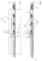
- the sheet 10 is conveyed by means of the conveyor belt 2 against a leading edge stopper 3.
- a leading edge stopper 3 At least one roller 5, 5 'rests on the conveyor belt 2 or sheet 10.
- the sheet 10 is conveyed between rollers 5, 5 ', 6, 13 and a conveyor belt 2 against a leading edge stop.
- the rollers 5, b 13 are in this case rotatably and pivotally mounted on a common carrier. In this way, on the one hand, it is supported that the sheets are conveyed exactly straight in the transport direction, in the embodiment 100, a springback of the sheet upon impact with the front edge stop is positively influenced, in the embodiment 100 'a format-dependent setting is made possible.
- rollers 5, 5 ' are pivoted in dependence on the position of the folding blade 9 from an active position to an inactive position, the folding operation is not adversely affected by frictional forces between the sheet 10 and rollers 5, 5' adversely.
- rollers 5 and 13 are pivotally mounted on a common support 12 via levers 11, 11 'and can by means of driving pins 7, 7', which are fixed to a push rod 8, are pivoted. These embodiments are particularly easy to manufacture and controllable.
- the reciprocating movement of the push rod 8 is caused by a pneumatic cylinder in response to signals from a sensor.
- a pneumatic cylinder in response to signals from a sensor.
- the roller 13 depending on the sheet format be pivoted, wherein the roller 5 'is mounted in the vicinity or on the leading edge stopper 3.
- the roller 5 ' must be clocked, because only one role, namely the role 5' gets up on the bow and reduces the bouncing.
- the timing of the roller 5 ' is done either via pivoting lever 11' or via a control element 14 or a lifting element 16. All these solutions enable a simple and rapid adjustment of the roller 5 '.
- the sheet 10 is transported via an inlet plate 1 by means of rollers 5 and 6, the spring-loaded (not shown) are biased in the direction of the conveyor belts 2, in the transport direction A to the leading edge stop 3 of a Schwertfalzwerkes.
- the sheet 10 is always aligned longitudinally to the subsequent folding blade 9 (see Fig. 3 ).
- the leading edge stop positions the sheet 10 at the leading edge.
- the kinetic energy of the sheet 10 causes the sheet to rebound differently depending on the speed of transport following the impact on the leading edge fence.
- a plurality of rollers 5 are placed on the sheet 10.
- the rollers 5 have a fixed distance to each other in the paper direction, which ensures that depending on the format of the sheet always at least one roller rests on the sheet.
- rollers 5 are rotatably and pivotally attached to a common carrier 12 via lever 11. They are biased by springs, not shown, in the direction of the conveyor belt 2. Between carrier 12 and lever 11 is a push rod 8, which by a device, not shown, for example, a pneumatic cylinder, reciprocates (arrow D in Fig. 4 ) can be.
- the driving pins 7 either come into contact with the levers 11 and lift the rollers 5 from the sheet 10 or get out of engagement with the levers 11 and the rollers 5 are lowered due to the Spring force on the conveyor belt 2 back.
- a sensor 4 which may be formed, for example, as a light sensor.
- the incoming sheet 10 passes with the leading edge of the sensor 4, which is attached to or in the vicinity of the leading edge stopper 3.
- the sensor 4 is now covered.
- the path from the leading edge lug 3 to the sensor 4 is fixed and known.
- the period between the time at which the folded sheet 10 covered with the front edge of the sensor, and the time at which the folding blade 9 extends downward, is dependent on the time in which the signatures 10 the distance from the sensor 4 to to the leading edge stop 3 and, secondly, the settling time of the signature at the leading edge stop.
- the settling time can be selected and set by the operator.
- the rollers 5 pivot by means of the pull rod upwards and release the contact with the folded sheet.
- the rollers 5 pivot down again. Before the next sheet is thus conveyed in the direction of the leading edge stop, the folding blade lifts off and the rollers 5 lower again onto the conveyor belt 2.
- the control for triggering the folding blade and the pneumatic cylinder is done via a control unit, not shown.
- the sensor 4 can also be mounted directly on the front edge stop 3.
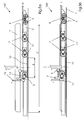
- a further device 100 ' according to the invention is shown.
- the sheet 10 is transported via the inlet plate 1 in the transport direction A by means of the conveyor belts 2 to the leading edge stopper 3.
- the transport of the sheet 10 is supported by the rollers 6, which stand up on the conveyor belt and further by rollers 13, which can be switched on or off depending on the sheet format, which will be described below in particular in connection with the description of Fig. 7a - 7c will be explained in more detail.
- roller 5 ' At or near the leading edge stop, another roll 5 'is attached.
- This roller 5 ' is biased by a spring, not shown, in the direction of the conveyor belt 2.
- the roller 5 ' stands on the sheet 10 as soon as it comes close to the leading edge stopper 3.
- a rebounding of the sheet is reduced and in particular avoided that the sheet bulges when hitting the leading edge stop and forms a wave.
- the roller 5 '(or the rollers 5') would interfere because, due to the frictional connection, increased friction between the sheet 10 and the roller 5 would adversely affect the folding operation. Therefore, the roller 5 'is lifted off the sheet before striking the folding blade 9 on the sheet, as in Fig. 5b shown.
- roller 5 ' is rotatably and pivotally attached via a lever 11' at or in the vicinity of the leading edge stopper 3.
- the incoming sheet 10 passes with its leading edge the sensor 4, which is also mounted on or in the vicinity of the leading edge stop, and already detected arc when they are still on a path to the leading edge stop.
- the path from the leading edge stop 3 to the sensor 4 is fixed and known.
- the period between the time at which the folded sheet 10 covered with the leading edge of the sensor, and the time at which the folding blade 9 extends downwards, thus, on the one hand depends on the time in which the signatures 10 the way from the sensor. 4 travels to the leading edge stop 3, and secondly from the settling time of the Fold sheet at leading edge stop 3.
- the settling time can be selected and set by the operator.
- the roller 5 Immediately before the folding blade 9 extends downward, the roller 5 'pivots in response to the movement of a control element 14 upwards and triggers contact with the signatures.
- the control element 14 can be moved by a lifting cylinder, electromagnet or the like.
- the roller pivots 5 'back down. So before the next sheet 10 is conveyed in the direction of the leading edge stop 3, the folding blade has been lifted and the roll 5 'has been lowered onto the conveyor belt 2 again.
- rollers 13 can be lowered onto the conveyor belt 2 in order to support the transport of the sheets 10. So that these rollers 13 do not interfere with the folding process on the one hand and, on the other hand, they do not have to be moved clockwise up and down as the roller 5 ', these rollers 13 can be switched on or off depending on the format, as in FIGS Fig. 7a to 7c shown.
- the rollers 13 are pivotally mounted on a common carrier 12 via lever 11 'and can by means of driving pins 7', which are fixed to a push rod 8, are pivoted.
- the movement of the push rod 8 can be done manually or automatically, for example by means of a pneumatic cylinder, which is not shown in detail.
- Fig. 7a shows a detail of the state of the rollers 13 at a minimum sheet size.
- the rollers 13 are placed inside the feeder that all rollers 13 can be lowered on the conveyor belt 2, since they no longer touch the sheet 10 when it rests on the leading edge stopper 3.
- Fig. 7b shows a detail of the state of the rollers 13 in a medium sheet format.
- the downstream in the transport direction roller would touch the sheet 10 when it rests against the leading edge stopper 3. Therefore, the push rod 8 is moved by the adjustment G against the sheet transport direction A. As a result, the driving pin 7 'lifts the lever 11' and thus the roller 13.
- Fig. 7c shows a detail of the state of the rollers 13 at a maximum Sheet size.
- the push rod 8 is moved by the displacement H against the transport direction A, which causes all the rollers 13 via the driving pins 7 ', which act on the lever 11 ', are lifted.
- the exemplary embodiment shows only two rollers 13 by way of example. However, the number of rollers 13 can be selected as desired.
- FIG. 8a to 8d the sequence of movements of an alternative roller 5 'is shown, which can not be switched on or off via levers 11', as described above, but directly via a corresponding lifting element 16.
- This alternative roller 5 ' is also in the vicinity of the front edge stop 3 appropriate and effective.
- the roller 5 ' is mounted in a fork 15.
- the fork 15 is movable in the axial direction of the piston rod 20.
- the mobility is made possible by a slot 17 in the fork 15.
- the fork 15 is secured by a pin 18. Due to the spring force of the compression spring 19, which is supported on one side on the fork 15 and on the other side on the lifting element 16, the roller 5 'is pressed against the conveyor belt 2. If the conveyor belt 2 moves, the roller 5 'thereby rotates and produces a driving force, which is later transferred to the sheet 10 as soon as it comes into the area of the roller 5'.
- Fig. 8b shows the role in the lowered state on the conveyor belt.
- the roller 5 passeses, he raises the role against the spring force by the spring travel E upwards, as in Fig. 8c shown.
- the roller 5 is moved by a lifting element by a stroke F upwards so that it lifts off the sheet 10, as in Fig. 8d shown.
- This stroke is exercised just before the sheet is pressed with the folding blade between folding rollers not shown here.
- the hub is, as already shown above, controlled by a sensor and associated control.
- a lifting element for example, pneumatic cylinders or electromagnets or the like come into question.
Landscapes
- Folding Of Thin Sheet-Like Materials, Special Discharging Devices, And Others (AREA)
- Registering Or Overturning Sheets (AREA)
Claims (17)
- Dispositif (100, 100') pour le positionnement de feuilles (10) déplacées dans une machine de pliage par au moins un groupe de couteaux de pliage à couteaux , se composant au moins d'une bande de transport inférieure (2) et d'au moins un rouleau (5, 5') qui s'applique sur la bande de transport, les feuilles (10) étant transportées à l'aide de la bande de transport en direction d'une butée avant (3),
caractérisé en ce qu'au moins un rouleau (5, 5') est mobile en fonction de la position du couteau de pliage (9) d'une position active dans laquelle elle touche la feuille (10) et une positon inactive dans laquelle elle est soulevée par la feuille (10). - Dispositif (100) selon la revendication 1, caractérisé en ce que plusieurs rouleaux (5, 6) s'appliquent sur la bande de transport, les rouleaux (5) étant fixés sur un support commun (12) de manière rotative et pivotante.
- Dispositif (100') selon la revendication 1, caractérisé en ce que plusieurs rouleaux (5', 6, 13) s'appliquent sur la bande de transport, les rouleaux (5) étant fixés sur un support commun (12) de manière rotative et pivotante.
- Dispositif (100, 100') selon la revendication 1, caractérisé en ce que les rouleaux (5 13) sont fixés de manière pivotante sur le support (12) par un levier (11, 11').
- Dispositif (100, 100') selon la revendication 4, caractérisé en ce que le levier (11, 11) est basculé par des broches d'entraînement (7, 7') qui sont fixées sur une tige de traction (8).
- Dispositif (100, 100') selon la revendication 2, caractérisé en ce que la tige de traction (8) est déplacée en va et vient par un vérin pneumatique.
- Dispositif (100) selon l'une des revendications 4 à 6, caractérisé en ce que les rouleaux (5) sont pivotés en fonction de signaux d'un capteur.
- Dispositif (100') selon l'une des revendications 4 à 6, caractérisé en ce que les rouleaux (13) sont pivotés en fonction du format de feuille.
- Dispositif (100') selon la revendication 1, caractérisé en ce qu'au moins un rouleau (5') est placé sur ou à proximité de la butée de bord avant (3).
- Dispositif (100') selon la revendication 1 ou 9, caractérisé en ce qu'au moins un rouleau (5') est fixé de manière pivotante par un levier (11').
- Dispositif selon la revendication 10, caractérisé en ce que le levier (11') d'au moins un rouleau (5') est basculé par un élément de commande (14).
- Dispositif selon la revendication 1 ou 9, caractérisé en ce que le rouleau (5') est logé dans une fourche (15) qui est mobile dans la direction axiale d'une tige de piston (20) d'un élément de levage (16).
- Dispositif selon la revendication 12, caractérisé en ce que la fourche (15) est fixée et bloquée contre la torsion sur la tige de piston (20) par une cheville (18).
- Dispositif selon la revendication 12 ou 13, caractérisé en ce qu'un ressort de pression (19) est disposé entre l'élément de levage (16) et la fourche (15).
- Dispositif selon l'une des revendications 12 à 14, caractérisé en ce que l'élément de levage est un vérin pneumatique.
- Dispositif selon l'une des revendications 12 15, caractérisé en ce que l'élément de levage est un électroaimant.
- Procédé pour le positionnement de feuilles déplacées (10) dans une machine de pliage avec au moins un groupe de pliage à couteaux, caractérisé par les étapes suivantes :a) transport d'une feuille en direction d'une butée de bord avant (3)b) détermination de la position du bord avant de la feuille (10) au moyen d'un capteur (4)c) Déclenchement du couteau de pliage (9) en fonction du trajet restant à parcourir de la feuille (10) jusqu'à la butée de bord avant (3) et d'un temps de repos préréglé de la feuille (10),d) soulèvement d'au moins un rouleau (5, 5') qui presse la feuille (10) contre une bande de transport (2) de sorte que lors de l'impact du couteau de pliage (9) avec la feuille (10), au moins un rouleau ne touche plus la feuille,e) abaissement d'au moins un rouleau (5, 5') si la feuille (10) ne recouvre plus le capteur (4).
Applications Claiming Priority (1)
| Application Number | Priority Date | Filing Date | Title |
|---|---|---|---|
| DE102006042878A DE102006042878A1 (de) | 2006-09-13 | 2006-09-13 | Vorrichtung zum Positionieren einer Hinterkante von Bogen |
Publications (3)
| Publication Number | Publication Date |
|---|---|
| EP1900669A2 EP1900669A2 (fr) | 2008-03-19 |
| EP1900669A3 EP1900669A3 (fr) | 2009-11-04 |
| EP1900669B1 true EP1900669B1 (fr) | 2012-03-07 |
Family
ID=38826550
Family Applications (1)
| Application Number | Title | Priority Date | Filing Date |
|---|---|---|---|
| EP07114492A Not-in-force EP1900669B1 (fr) | 2006-09-13 | 2007-08-17 | Dispositif destiné au positionnement d'une arête arrière de feuille |
Country Status (6)
| Country | Link |
|---|---|
| EP (1) | EP1900669B1 (fr) |
| JP (1) | JP5442191B2 (fr) |
| CN (1) | CN101143663B (fr) |
| AT (1) | ATE548311T1 (fr) |
| DE (1) | DE102006042878A1 (fr) |
| PT (1) | PT1900669E (fr) |
Families Citing this family (4)
| Publication number | Priority date | Publication date | Assignee | Title |
|---|---|---|---|---|
| US20120238422A1 (en) * | 2009-12-10 | 2012-09-20 | Horizon International Inc. | Knife folding machine |
| DE102011018859A1 (de) * | 2011-04-28 | 2012-10-31 | Heidelberger Druckmaschinen Aktiengesellschaft | Falzmaschine mit Transportvorrichtung |
| CN104444554B (zh) * | 2014-09-29 | 2017-09-01 | 武汉恒飞电气科技有限公司 | 自动衣料折叠机 |
| JP7120622B2 (ja) | 2018-10-17 | 2022-08-17 | ホリゾン・インターナショナル株式会社 | ナイフ折り機及びその制御装置並びにナイフ折り機の制御方法 |
Family Cites Families (13)
| Publication number | Priority date | Publication date | Assignee | Title |
|---|---|---|---|---|
| JPS6143803Y2 (fr) * | 1979-05-09 | 1986-12-10 | ||
| DE8406391U1 (de) * | 1984-03-01 | 1984-07-19 | Stahl Gmbh & Co Maschinenfabrik, 7140 Ludwigsburg | Falzmaschine mit niederhalteeinrichtung |
| DE4213017C2 (de) * | 1992-04-21 | 1998-03-19 | Heidelberger Druckmasch Ag | Bogenanleger an Druckmaschinen |
| DE9304281U1 (de) * | 1993-03-22 | 1993-05-13 | Stahl Gmbh & Co Maschinenfabrik, 7140 Ludwigsburg | Vorrichtung zum Belasten von Falzbogen |
| US5685539A (en) * | 1995-07-05 | 1997-11-11 | Pitney Bowes Inc. | Disk transport for paper sheets |
| DE19606821A1 (de) * | 1996-02-23 | 1997-08-28 | Boewe Systec Ag | Schwertfalzwerk |
| JP2786617B2 (ja) * | 1996-05-16 | 1998-08-13 | 三菱重工業株式会社 | 折機のシート等の搬送装置 |
| JP3776219B2 (ja) * | 1997-09-03 | 2006-05-17 | ホリゾン・インターナショナル株式会社 | 用紙のナイフ折り装置 |
| DE29904757U1 (de) * | 1999-03-16 | 1999-06-17 | Heidelberger Druckmaschinen Ag, 69115 Heidelberg | Falzmaschine mit Niederhalteeinrichtung |
| JP3692322B2 (ja) * | 2000-12-25 | 2005-09-07 | 三菱重工業株式会社 | 折帖搬送装置 |
| JP3999057B2 (ja) * | 2002-06-13 | 2007-10-31 | シャープ株式会社 | 整合装置、および、それを備えた画像形成システム |
| DE102004015963A1 (de) | 2004-04-01 | 2005-11-10 | Koenig & Bauer Ag | Systems mit alternativen Bearbeitungsstrecken zur Weiterverarbeitung von Produkten, Längsfalzapparat sowie Verfahren zum synchronen Betrieb eines Falzapparates |
| US7703599B2 (en) * | 2004-04-19 | 2010-04-27 | Curt G. Joa, Inc. | Method and apparatus for reversing direction of an article |
-
2006
- 2006-09-13 DE DE102006042878A patent/DE102006042878A1/de not_active Withdrawn
-
2007
- 2007-08-17 PT PT07114492T patent/PT1900669E/pt unknown
- 2007-08-17 AT AT07114492T patent/ATE548311T1/de active
- 2007-08-17 EP EP07114492A patent/EP1900669B1/fr not_active Not-in-force
- 2007-09-13 CN CN2007101547595A patent/CN101143663B/zh not_active Expired - Fee Related
- 2007-09-13 JP JP2007237930A patent/JP5442191B2/ja active Active
Also Published As
| Publication number | Publication date |
|---|---|
| DE102006042878A1 (de) | 2008-03-27 |
| JP5442191B2 (ja) | 2014-03-12 |
| CN101143663B (zh) | 2012-04-25 |
| ATE548311T1 (de) | 2012-03-15 |
| CN101143663A (zh) | 2008-03-19 |
| EP1900669A2 (fr) | 2008-03-19 |
| PT1900669E (pt) | 2012-05-07 |
| JP2008069011A (ja) | 2008-03-27 |
| EP1900669A3 (fr) | 2009-11-04 |
Similar Documents
| Publication | Publication Date | Title |
|---|---|---|
| EP2727869B1 (fr) | Dispositif et procédé destinés à plier des feuilles imprimées | |
| DE3153613C2 (fr) | ||
| EP4320060B1 (fr) | Machine d'impression comportant plusieurs stations de traitement des feuilles | |
| DE102013008533A1 (de) | Anleger für einen Klebebinder | |
| EP1900669A2 (fr) | Dispositif destiné au positionnement d'une arête arrière de feuille | |
| EP3533609B1 (fr) | Dispositif et procédé de traitement ultérieur séquentiel de feuilles imprimées | |
| EP1939008B1 (fr) | Assembleuse et brocheuse dotée d'une chaîne variable | |
| EP0225994B1 (fr) | Procédé et dispositif pour placer et freiner des feuilles ou des feuilles en paquet imprimées dans une presse à imprimer | |
| DE2337210A1 (de) | Klemmgreifer fuer bogenverarbeitende, intermittierend foerdernde maschinen, insbesondere druck- und stanzmaschinen | |
| DE102017205868A1 (de) | Transportsystem für bogenförmige Elemente | |
| EP2727868B1 (fr) | Dispositif et procédé destinés à plier des feuilles imprimées | |
| EP1770036B1 (fr) | Dispositif de guidage de feuilles pour un margeur de feuilles | |
| EP2248748B1 (fr) | Dispositif de positionnement de feuilles dans une plieuse | |
| EP1900668B1 (fr) | Dispositif destiné au positionnement d'une arête arrière de feuille dans une plieuse à lame | |
| EP1900660B1 (fr) | Dispositif destiné au positionnement d'une arête arrière de feuille | |
| DE7824283U1 (de) | Automatische entnahmevorrichtung fuer eine zusammentragevorrichtung | |
| EP2181857B1 (fr) | Assembleuse dotée d'un pas de chaîne variable | |
| DE202017103367U1 (de) | Vorrichtung zum Stoppen eines Fördergutes auf einem Förderer | |
| DE102021006551A1 (de) | Maschinenanordnung mit mehreren jeweils Bogen bearbeitenden Bearbeitungsstationen | |
| WO2016030167A1 (fr) | Sacoche | |
| DE102007028132A1 (de) | Bogenausleger einer Druckmaschine | |
| DE102008042900A1 (de) | Bogenbremse vor einem Auslegerstapel einer bogenverarbeitenden Maschine mit umlaufend geführten Bremsbändern | |
| DE102005009454B4 (de) | Abnahmegreifer im Bogenausleger einer Druckmaschine | |
| DE10024018B4 (de) | Vorrichtung zum Bilden eines Bogenstroms von sich schuppenartig teilweise überdeckenden Bogen | |
| EP2088107B1 (fr) | Plieuse à poches |
Legal Events
| Date | Code | Title | Description |
|---|---|---|---|
| PUAI | Public reference made under article 153(3) epc to a published international application that has entered the european phase |
Free format text: ORIGINAL CODE: 0009012 |
|
| AK | Designated contracting states |
Kind code of ref document: A2 Designated state(s): AT BE BG CH CY CZ DE DK EE ES FI FR GB GR HU IE IS IT LI LT LU LV MC MT NL PL PT RO SE SI SK TR |
|
| AX | Request for extension of the european patent |
Extension state: AL BA HR MK YU |
|
| PUAL | Search report despatched |
Free format text: ORIGINAL CODE: 0009013 |
|
| AK | Designated contracting states |
Kind code of ref document: A3 Designated state(s): AT BE BG CH CY CZ DE DK EE ES FI FR GB GR HU IE IS IT LI LT LU LV MC MT NL PL PT RO SE SI SK TR |
|
| AX | Request for extension of the european patent |
Extension state: AL BA HR MK RS |
|
| 17P | Request for examination filed |
Effective date: 20100504 |
|
| AKX | Designation fees paid |
Designated state(s): AT BE BG CH CY CZ DE DK EE ES FI FR GB GR HU IE IS IT LI LT LU LV MC MT NL PL PT RO SE SI SK TR |
|
| GRAP | Despatch of communication of intention to grant a patent |
Free format text: ORIGINAL CODE: EPIDOSNIGR1 |
|
| GRAS | Grant fee paid |
Free format text: ORIGINAL CODE: EPIDOSNIGR3 |
|
| GRAA | (expected) grant |
Free format text: ORIGINAL CODE: 0009210 |
|
| AK | Designated contracting states |
Kind code of ref document: B1 Designated state(s): AT BE BG CH CY CZ DE DK EE ES FI FR GB GR HU IE IS IT LI LT LU LV MC MT NL PL PT RO SE SI SK TR |
|
| REG | Reference to a national code |
Ref country code: GB Ref legal event code: FG4D Free format text: NOT ENGLISH |
|
| REG | Reference to a national code |
Ref country code: AT Ref legal event code: REF Ref document number: 548311 Country of ref document: AT Kind code of ref document: T Effective date: 20120315 Ref country code: CH Ref legal event code: EP |
|
| REG | Reference to a national code |
Ref country code: IE Ref legal event code: FG4D Free format text: LANGUAGE OF EP DOCUMENT: GERMAN |
|
| REG | Reference to a national code |
Ref country code: DE Ref legal event code: R096 Ref document number: 502007009423 Country of ref document: DE Effective date: 20120503 |
|
| REG | Reference to a national code |
Ref country code: PT Ref legal event code: SC4A Free format text: AVAILABILITY OF NATIONAL TRANSLATION Effective date: 20120419 |
|
| REG | Reference to a national code |
Ref country code: NL Ref legal event code: VDEP Effective date: 20120307 |
|
| PG25 | Lapsed in a contracting state [announced via postgrant information from national office to epo] |
Ref country code: NL Free format text: LAPSE BECAUSE OF FAILURE TO SUBMIT A TRANSLATION OF THE DESCRIPTION OR TO PAY THE FEE WITHIN THE PRESCRIBED TIME-LIMIT Effective date: 20120307 Ref country code: LT Free format text: LAPSE BECAUSE OF FAILURE TO SUBMIT A TRANSLATION OF THE DESCRIPTION OR TO PAY THE FEE WITHIN THE PRESCRIBED TIME-LIMIT Effective date: 20120307 |
|
| LTIE | Lt: invalidation of european patent or patent extension |
Effective date: 20120307 |
|
| PG25 | Lapsed in a contracting state [announced via postgrant information from national office to epo] |
Ref country code: GR Free format text: LAPSE BECAUSE OF FAILURE TO SUBMIT A TRANSLATION OF THE DESCRIPTION OR TO PAY THE FEE WITHIN THE PRESCRIBED TIME-LIMIT Effective date: 20120608 Ref country code: FI Free format text: LAPSE BECAUSE OF FAILURE TO SUBMIT A TRANSLATION OF THE DESCRIPTION OR TO PAY THE FEE WITHIN THE PRESCRIBED TIME-LIMIT Effective date: 20120307 Ref country code: LV Free format text: LAPSE BECAUSE OF FAILURE TO SUBMIT A TRANSLATION OF THE DESCRIPTION OR TO PAY THE FEE WITHIN THE PRESCRIBED TIME-LIMIT Effective date: 20120307 |
|
| PG25 | Lapsed in a contracting state [announced via postgrant information from national office to epo] |
Ref country code: CY Free format text: LAPSE BECAUSE OF FAILURE TO SUBMIT A TRANSLATION OF THE DESCRIPTION OR TO PAY THE FEE WITHIN THE PRESCRIBED TIME-LIMIT Effective date: 20120307 |
|
| PG25 | Lapsed in a contracting state [announced via postgrant information from national office to epo] |
Ref country code: SE Free format text: LAPSE BECAUSE OF FAILURE TO SUBMIT A TRANSLATION OF THE DESCRIPTION OR TO PAY THE FEE WITHIN THE PRESCRIBED TIME-LIMIT Effective date: 20120307 Ref country code: PL Free format text: LAPSE BECAUSE OF FAILURE TO SUBMIT A TRANSLATION OF THE DESCRIPTION OR TO PAY THE FEE WITHIN THE PRESCRIBED TIME-LIMIT Effective date: 20120307 Ref country code: RO Free format text: LAPSE BECAUSE OF FAILURE TO SUBMIT A TRANSLATION OF THE DESCRIPTION OR TO PAY THE FEE WITHIN THE PRESCRIBED TIME-LIMIT Effective date: 20120307 Ref country code: SI Free format text: LAPSE BECAUSE OF FAILURE TO SUBMIT A TRANSLATION OF THE DESCRIPTION OR TO PAY THE FEE WITHIN THE PRESCRIBED TIME-LIMIT Effective date: 20120307 Ref country code: CZ Free format text: LAPSE BECAUSE OF FAILURE TO SUBMIT A TRANSLATION OF THE DESCRIPTION OR TO PAY THE FEE WITHIN THE PRESCRIBED TIME-LIMIT Effective date: 20120307 Ref country code: EE Free format text: LAPSE BECAUSE OF FAILURE TO SUBMIT A TRANSLATION OF THE DESCRIPTION OR TO PAY THE FEE WITHIN THE PRESCRIBED TIME-LIMIT Effective date: 20120307 Ref country code: IS Free format text: LAPSE BECAUSE OF FAILURE TO SUBMIT A TRANSLATION OF THE DESCRIPTION OR TO PAY THE FEE WITHIN THE PRESCRIBED TIME-LIMIT Effective date: 20120707 |
|
| PG25 | Lapsed in a contracting state [announced via postgrant information from national office to epo] |
Ref country code: SK Free format text: LAPSE BECAUSE OF FAILURE TO SUBMIT A TRANSLATION OF THE DESCRIPTION OR TO PAY THE FEE WITHIN THE PRESCRIBED TIME-LIMIT Effective date: 20120307 |
|
| PLBE | No opposition filed within time limit |
Free format text: ORIGINAL CODE: 0009261 |
|
| STAA | Information on the status of an ep patent application or granted ep patent |
Free format text: STATUS: NO OPPOSITION FILED WITHIN TIME LIMIT |
|
| PG25 | Lapsed in a contracting state [announced via postgrant information from national office to epo] |
Ref country code: DK Free format text: LAPSE BECAUSE OF FAILURE TO SUBMIT A TRANSLATION OF THE DESCRIPTION OR TO PAY THE FEE WITHIN THE PRESCRIBED TIME-LIMIT Effective date: 20120307 |
|
| 26N | No opposition filed |
Effective date: 20121210 |
|
| BERE | Be: lapsed |
Owner name: HEIDELBERGER DRUCKMASCHINEN A.G. Effective date: 20120831 |
|
| PG25 | Lapsed in a contracting state [announced via postgrant information from national office to epo] |
Ref country code: IT Free format text: LAPSE BECAUSE OF FAILURE TO SUBMIT A TRANSLATION OF THE DESCRIPTION OR TO PAY THE FEE WITHIN THE PRESCRIBED TIME-LIMIT Effective date: 20120307 |
|
| PG25 | Lapsed in a contracting state [announced via postgrant information from national office to epo] |
Ref country code: MC Free format text: LAPSE BECAUSE OF NON-PAYMENT OF DUE FEES Effective date: 20120831 |
|
| REG | Reference to a national code |
Ref country code: DE Ref legal event code: R097 Ref document number: 502007009423 Country of ref document: DE Effective date: 20121210 |
|
| GBPC | Gb: european patent ceased through non-payment of renewal fee |
Effective date: 20120817 |
|
| PG25 | Lapsed in a contracting state [announced via postgrant information from national office to epo] |
Ref country code: ES Free format text: LAPSE BECAUSE OF FAILURE TO SUBMIT A TRANSLATION OF THE DESCRIPTION OR TO PAY THE FEE WITHIN THE PRESCRIBED TIME-LIMIT Effective date: 20120618 |
|
| REG | Reference to a national code |
Ref country code: FR Ref legal event code: ST Effective date: 20130430 |
|
| REG | Reference to a national code |
Ref country code: IE Ref legal event code: MM4A |
|
| PG25 | Lapsed in a contracting state [announced via postgrant information from national office to epo] |
Ref country code: BE Free format text: LAPSE BECAUSE OF NON-PAYMENT OF DUE FEES Effective date: 20120831 |
|
| PG25 | Lapsed in a contracting state [announced via postgrant information from national office to epo] |
Ref country code: IE Free format text: LAPSE BECAUSE OF NON-PAYMENT OF DUE FEES Effective date: 20120817 Ref country code: BG Free format text: LAPSE BECAUSE OF FAILURE TO SUBMIT A TRANSLATION OF THE DESCRIPTION OR TO PAY THE FEE WITHIN THE PRESCRIBED TIME-LIMIT Effective date: 20120607 Ref country code: GB Free format text: LAPSE BECAUSE OF NON-PAYMENT OF DUE FEES Effective date: 20120817 |
|
| PG25 | Lapsed in a contracting state [announced via postgrant information from national office to epo] |
Ref country code: FR Free format text: LAPSE BECAUSE OF NON-PAYMENT OF DUE FEES Effective date: 20120831 |
|
| REG | Reference to a national code |
Ref country code: AT Ref legal event code: MM01 Ref document number: 548311 Country of ref document: AT Kind code of ref document: T Effective date: 20120831 |
|
| PG25 | Lapsed in a contracting state [announced via postgrant information from national office to epo] |
Ref country code: AT Free format text: LAPSE BECAUSE OF NON-PAYMENT OF DUE FEES Effective date: 20120831 |
|
| PG25 | Lapsed in a contracting state [announced via postgrant information from national office to epo] |
Ref country code: MT Free format text: LAPSE BECAUSE OF FAILURE TO SUBMIT A TRANSLATION OF THE DESCRIPTION OR TO PAY THE FEE WITHIN THE PRESCRIBED TIME-LIMIT Effective date: 20120307 |
|
| PG25 | Lapsed in a contracting state [announced via postgrant information from national office to epo] |
Ref country code: TR Free format text: LAPSE BECAUSE OF FAILURE TO SUBMIT A TRANSLATION OF THE DESCRIPTION OR TO PAY THE FEE WITHIN THE PRESCRIBED TIME-LIMIT Effective date: 20120307 |
|
| PG25 | Lapsed in a contracting state [announced via postgrant information from national office to epo] |
Ref country code: LU Free format text: LAPSE BECAUSE OF NON-PAYMENT OF DUE FEES Effective date: 20120817 |
|
| PG25 | Lapsed in a contracting state [announced via postgrant information from national office to epo] |
Ref country code: HU Free format text: LAPSE BECAUSE OF FAILURE TO SUBMIT A TRANSLATION OF THE DESCRIPTION OR TO PAY THE FEE WITHIN THE PRESCRIBED TIME-LIMIT Effective date: 20070817 |
|
| PGFP | Annual fee paid to national office [announced via postgrant information from national office to epo] |
Ref country code: CH Payment date: 20140821 Year of fee payment: 8 |
|
| PGFP | Annual fee paid to national office [announced via postgrant information from national office to epo] |
Ref country code: PT Payment date: 20140218 Year of fee payment: 8 |
|
| REG | Reference to a national code |
Ref country code: PT Ref legal event code: MM4A Free format text: LAPSE DUE TO NON-PAYMENT OF FEES Effective date: 20160217 |
|
| REG | Reference to a national code |
Ref country code: CH Ref legal event code: PL |
|
| PG25 | Lapsed in a contracting state [announced via postgrant information from national office to epo] |
Ref country code: LI Free format text: LAPSE BECAUSE OF NON-PAYMENT OF DUE FEES Effective date: 20150831 Ref country code: CH Free format text: LAPSE BECAUSE OF NON-PAYMENT OF DUE FEES Effective date: 20150831 |
|
| PG25 | Lapsed in a contracting state [announced via postgrant information from national office to epo] |
Ref country code: PT Free format text: LAPSE BECAUSE OF NON-PAYMENT OF DUE FEES Effective date: 20160217 |
|
| P01 | Opt-out of the competence of the unified patent court (upc) registered |
Effective date: 20230425 |
|
| PGFP | Annual fee paid to national office [announced via postgrant information from national office to epo] |
Ref country code: DE Payment date: 20240831 Year of fee payment: 18 |
|
| REG | Reference to a national code |
Ref country code: DE Ref legal event code: R119 Ref document number: 502007009423 Country of ref document: DE |