EP1900894A1 - Modularer verschlusslaschenmechanismus - Google Patents
Modularer verschlusslaschenmechanismus Download PDFInfo
- Publication number
- EP1900894A1 EP1900894A1 EP06778449A EP06778449A EP1900894A1 EP 1900894 A1 EP1900894 A1 EP 1900894A1 EP 06778449 A EP06778449 A EP 06778449A EP 06778449 A EP06778449 A EP 06778449A EP 1900894 A1 EP1900894 A1 EP 1900894A1
- Authority
- EP
- European Patent Office
- Prior art keywords
- latch
- casing
- carriage
- door
- rotation shaft
- Prior art date
- Legal status (The legal status is an assumption and is not a legal conclusion. Google has not performed a legal analysis and makes no representation as to the accuracy of the status listed.)
- Withdrawn
Links
Images




Classifications
-
- E—FIXED CONSTRUCTIONS
- E05—LOCKS; KEYS; WINDOW OR DOOR FITTINGS; SAFES
- E05B—LOCKS; ACCESSORIES THEREFOR; HANDCUFFS
- E05B65/00—Locks or fastenings for special use
- E05B65/10—Locks or fastenings for special use for panic or emergency doors
- E05B65/1046—Panic bars
- E05B65/1053—Panic bars sliding towards and away form the door
-
- E—FIXED CONSTRUCTIONS
- E05—LOCKS; KEYS; WINDOW OR DOOR FITTINGS; SAFES
- E05B—LOCKS; ACCESSORIES THEREFOR; HANDCUFFS
- E05B65/00—Locks or fastenings for special use
- E05B65/10—Locks or fastenings for special use for panic or emergency doors
-
- E—FIXED CONSTRUCTIONS
- E05—LOCKS; KEYS; WINDOW OR DOOR FITTINGS; SAFES
- E05B—LOCKS; ACCESSORIES THEREFOR; HANDCUFFS
- E05B15/00—Other details of locks; Parts for engagement by bolts of fastening devices
- E05B15/10—Bolts of locks or night latches
- E05B15/102—Bolts having movable elements
-
- E—FIXED CONSTRUCTIONS
- E05—LOCKS; KEYS; WINDOW OR DOOR FITTINGS; SAFES
- E05C—BOLTS OR FASTENING DEVICES FOR WINGS, SPECIALLY FOR DOORS OR WINDOWS
- E05C9/00—Arrangements of simultaneously actuated bolts or other securing devices at well-separated positions on the same wing
- E05C9/04—Arrangements of simultaneously actuated bolts or other securing devices at well-separated positions on the same wing with two sliding bars moved in opposite directions when fastening or unfastening
- E05C9/046—Arrangements of simultaneously actuated bolts or other securing devices at well-separated positions on the same wing with two sliding bars moved in opposite directions when fastening or unfastening with two interconnected mechanisms each driving one rod
-
- E—FIXED CONSTRUCTIONS
- E05—LOCKS; KEYS; WINDOW OR DOOR FITTINGS; SAFES
- E05C—BOLTS OR FASTENING DEVICES FOR WINGS, SPECIALLY FOR DOORS OR WINDOWS
- E05C9/00—Arrangements of simultaneously actuated bolts or other securing devices at well-separated positions on the same wing
- E05C9/04—Arrangements of simultaneously actuated bolts or other securing devices at well-separated positions on the same wing with two sliding bars moved in opposite directions when fastening or unfastening
- E05C9/047—Arrangements of simultaneously actuated bolts or other securing devices at well-separated positions on the same wing with two sliding bars moved in opposite directions when fastening or unfastening comprising key-operated locks, e.g. a lock cylinder to drive auxiliary deadbolts or latch bolts
-
- E—FIXED CONSTRUCTIONS
- E05—LOCKS; KEYS; WINDOW OR DOOR FITTINGS; SAFES
- E05C—BOLTS OR FASTENING DEVICES FOR WINGS, SPECIALLY FOR DOORS OR WINDOWS
- E05C9/00—Arrangements of simultaneously actuated bolts or other securing devices at well-separated positions on the same wing
- E05C9/04—Arrangements of simultaneously actuated bolts or other securing devices at well-separated positions on the same wing with two sliding bars moved in opposite directions when fastening or unfastening
- E05C9/048—Arrangements of simultaneously actuated bolts or other securing devices at well-separated positions on the same wing with two sliding bars moved in opposite directions when fastening or unfastening externally mounted on the wing, i.e. surface mounted
-
- E—FIXED CONSTRUCTIONS
- E05—LOCKS; KEYS; WINDOW OR DOOR FITTINGS; SAFES
- E05B—LOCKS; ACCESSORIES THEREFOR; HANDCUFFS
- E05B17/00—Accessories in connection with locks
- E05B17/20—Means independent of the locking mechanism for preventing unauthorised opening, e.g. for securing the bolt in the fastening position
- E05B17/2003—Preventing opening by insertion of a tool, e.g. flexible, between door and jamb to withdraw the bolt
-
- E—FIXED CONSTRUCTIONS
- E05—LOCKS; KEYS; WINDOW OR DOOR FITTINGS; SAFES
- E05B—LOCKS; ACCESSORIES THEREFOR; HANDCUFFS
- E05B63/00—Locks or fastenings with special structural characteristics
- E05B63/04—Locks or fastenings with special structural characteristics for alternative use on the right-hand or left-hand side of wings
- E05B63/042—Locks or fastenings with special structural characteristics for alternative use on the right-hand or left-hand side of wings constructed symmetrically
-
- E—FIXED CONSTRUCTIONS
- E05—LOCKS; KEYS; WINDOW OR DOOR FITTINGS; SAFES
- E05B—LOCKS; ACCESSORIES THEREFOR; HANDCUFFS
- E05B65/00—Locks or fastenings for special use
- E05B65/10—Locks or fastenings for special use for panic or emergency doors
- E05B65/1006—Locks or fastenings for special use for panic or emergency doors of the vertical rod type
-
- Y—GENERAL TAGGING OF NEW TECHNOLOGICAL DEVELOPMENTS; GENERAL TAGGING OF CROSS-SECTIONAL TECHNOLOGIES SPANNING OVER SEVERAL SECTIONS OF THE IPC; TECHNICAL SUBJECTS COVERED BY FORMER USPC CROSS-REFERENCE ART COLLECTIONS [XRACs] AND DIGESTS
- Y10—TECHNICAL SUBJECTS COVERED BY FORMER USPC
- Y10T—TECHNICAL SUBJECTS COVERED BY FORMER US CLASSIFICATION
- Y10T292/00—Closure fasteners
- Y10T292/08—Bolts
- Y10T292/0894—Spring arm
- Y10T292/0895—Operating means
Definitions
- the present invention relates to a closing latch modular mechanism which is designed to be used in particular in connection with the anti-panic function of a lock, either a domestic lock or, more especially, a lock installed in an emergency exit door of premises frequented by large numbers of people (dance halls, large shopping areas, shopping malls, office buildings, hospitals, etc.).
- the anti-panic function of a lock enables the door to be opened from the inside in all circumstances without having to use a key, and simply by actuating a handle or pushing or depressing a bar.
- This modular mechanism can be used in independently operable locks regardless of their actuating system, i.e. manual, automatic, mechanical or electromechanical; all that is necessary is that this system produces an action capable of activating the mechanism of the invention so as to effect the retraction of the latch.
- Anti-panic opening systems are obligatory in order to facilitate the rapid evacuation of people from areas where large numbers of people congregate, as well as in the domestic sector.
- the actuation of the mechanism must be smooth and require little force.
- the mechanism must be robust in order to resist attempts to force or break the lock, which can compromise the ease and facility of actuation needed to ensure the safety of people.
- the mechanism has to function reliably and be designed and constructed as simply as possible.
- one of these standards specifies that, in the rest state (that is to say, when no pressure is exerted on the door panel equipped with an anti-panic lock), this anti-panic lock can be opened by applying a maximum force of 80 N; the standard also specifies that the same lock can be opened by a force of 220 N when a force of 1000 N is exerted on the door, which is equivalent to the force exerted by four people who would be squashed against the door on account of the almost inevitable stampede caused by panic in emergency escape situations, for example when attempting to escape from a fire inside a locked building.
- this standard is to prevent the numerous fatalities which occur in such stampedes not on account of the direct action of the fire or of the accompanying danger, but by the fact that the bodies of people who are in front are increasingly crushed by people from behind, due to the fact that before the door is opened it is subjected to a pressure which already prevents it being opened subsequently and which is caused by people who, in trying to escape, are crushed against the door before they have been able to actuate the anti-panic bar that would open the door and thereby allow a mass exodus of the fleeing people.
- the difficulty is to satisfy these standards, which are aimed at improving the safety of people while at the same time ensuring an adequate security of property.
- the reason why the anti-panic mechanism is not activated when the door is subjected to a foreseeable pressure in cases of human stampede is due to the fact that, in the various designs of devices currently employed for this purpose, the operation to retract the latch is effected by friction between a surface of the latch and a surface of its lock, so that if an excessive pressure is exerted on such surfaces before the said retraction is initiated, then the mechanism is inactivated, which blocks the operation.
- a normal type of mechanism consists of a catch of conventional shape that has a bevelled front surface that rests against the lock when the door is in contact with the frame, as well as a longitudinal opposite surface that remains in contact with an internal wall of the lock, thereby preventing the door from being opened while the catch is not retracted, and in this type of mechanism the said retraction is effected by a linear frictional movement on the lock, whereby as soon as a pressure that is not too large is exerted on the locked door, although the opening of the anti-panic device is then actuated, the force of the latter will still not be able to retract the said latch.
- the rotation shaft can be displaced along a longitudinal path by connecting it to displaceable connecting rod-type means that are subjected to a force that is exerted by means of an electromagnet or a permanent magnet; in order to achieve the operative rotation of the latch the longitudinal path is combined with another, curved path which is traversed by a second shaft of the latch which is at the end of the curved convex surface which is opposite the most projecting part of the emergent position of the latch.
- both shafts of the latch can be displaced along both curved parts.
- the object of the present invention is a closing latch modular mechanism which comprises a mechanism casing, a latch head or latch per se, which has a conventional configuration with a bevelled surface and a longitudinal surface parallel to the plane of the door, a support for the latch, a rotation shaft of the latch, an anti-rotation device of the latch, a rotatory lever carrying the said anti-rotation device, a carriage that is displaceable longitudinally parallel to the plane of the door, and means for actuating the carriage, wherein the said latch is installed in the said support by means of the said rotation shaft, has a receptacle of semicircular cross-section elongated tangentially at its ends, which is parallel to the rotation shaft and is situated in its rear surface at a distance from the plane of the door which is suitably larger than that of the rotation shaft, and, in opposition to the said rotation shaft, this latch has a projection that in front abuts against a wall of the said support, the said rotation shaft being situated adjacent to the front
- the crosspiece thereof presses on the concavity of the rotatory lever and causes the latter to rotate in its rotational joint, thereby compressing the second torsion spring and displacing the anti-rotation device from its rear receptacle in the latch; then, when the door is pressed in the opening direction the simple action of the keeper on the latch causes this to rotate about its axis, releasing it into the cavity of the casing of the mechanism, which takes place with the compression of the first torsion spring, which in turn restores the starting position as soon as the door becomes separated from its frame.
- This proposed mechanism is sensitive, robust and reliable; it contains a small number of parts connected to one another in a simple manner, without the need for complex kinematic linkages involving a large number of movements between their component parts; to effect opening the latch is released simply by rotation about only one shaft, without involvement of the type of friction that is found in those solutions in which the latch is retracted longitudinally, sliding on the internal wall of the keeper, where blockages occur that prevent the door opening when subjected to the pressure of people who have fallen against the door on being squashed by others attempting to flee from imminent danger; this type of release satisfies the most stringent standard mentioned hereinbefore as regards the safety of people, while providing a high degree of security for property thanks to a high basic robustness, in which its design allows the anti-rotation device to be as solid and bulky as necessary, and in addition there is a wide margin for varying the dimensions of the remote rotatory lever to the advantage of the anti-rotation device with respect to the articulation of this lever and the concavity of
- the proposed mechanism is compatible with any type of lock and actuating technology provided that this is arranged so as to effect the traction of the carriage in the sense of displacing the anti-rotation device from its receptacle in the latch.
- an envisaged modification of the invention consists in that the said actuating means for the carriage comprise a puller (traction means) that is coupled to the carriage by means of a third track so that its working path and its longitudinal position are in conjunction with the travel length and the front and rear operating positions of the said carriage.
- the envisaged mechanism has a reversible design and construction for right-hand and left-hand doors, symmetrical with respect to the longitudinal mid plane of the latch, comprising a handle, a rotating plate, second and third rockers, first and second slide rims, and first and second locks actuated by a key, wherein the rotating plate is rotatably coupled to the handle, is longitudinally convex towards the floor of the casing, has two diametrically opposite leaves that are perpendicular to the said convexity, and is capable of adopting two disengaged and engaged handle operating positions that are respectively closer to or further from the floor of the casing, the said second and third rockers have their rotation shaft fixed to the casing, both have pivots rot
- the eccentric of the appropriate one of these locks is actuated, following which the corresponding rim is introduced underneath the rotating plate (by pushing the wedged edge of the first against the convexity of the latter), thereby separating it from the floor of the casing so that, on rotation, one of its leaves presses on the pivot of one of the rims (the corresponding one), effecting the retraction of the carriage and, thereby, causing the anti-rotation device to leave the receptacle of the latch; this operation allows access from the outside by authorised personnel.
- the second and third rockers have a pin that slidably engages in a groove of both first and second straightedge plates, which are slidably guided in the direction perpendicular to the travel of the latch and which are capable of acting respectively on top and bottom complementary locking points situated in the same vertical frame of the central locking means and/or in the doorsill and doorhead frames.
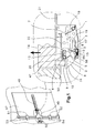
- a preferred embodiment of the object of the invention is illustrated in the accompanying drawings, and relates to a modular mechanism which (see Fig. 1 ) comprises a mechanism casing (1), a latch head or latch (2) per se, which has a conventional shape with a bevelled surface (8) and a longitudinal surface (9) parallel to the plane of the door (47), a support (3) of the latch (2), a rotation shaft (4) of the latch (2), an anti-rotation device (5) of the latch (2), a rotatory lever (6) carrying the said anti-rotation device (5), a carriage (7) that is displaceable longitudinally parallel to the plane of the door (47), and means for actuating the carriage (7), wherein the said latch (2) is installed in the said support (3) by means of the said rotation shaft (4), has a receptacle (11) of semicircular cross-section elongated tangentially at its ends, which is parallel to the rotation shaft (4) and is situated on its rear surface (10) at
- the receptacle (11) for the anti-rotation device (5) is related to the longitudinal mid plane of the latch (2); similarly, in accordance with a preferred embodiment, the said rotatory linkage (12) of the rotatory lever (6) is at a greater distance from the door (47) than is the side of the latch (2) opposite the longitudinal surface (9) thereof.
- FIG. 1 shows diagrammatically a door (47) with a generic locking system in which, apart from the central lock (48), there is a handle (30), an anti-panic push bar (49) and complementary top (51) and bottom (52) locking devices arranged both in the plane itself of the central lock (48) as well as in the doorsill and doorhead frames.
- the mechanism may be employed universally, namely for locking systems with a single conventional central lock (48), with an internal anti-panic handle (30), for cases where there are also top (51) and bottom (52) locking devices, for cases where the actuation is by means of a push-type (or lever-type) anti-panic bar (49), or for cases where the actuation is by electromechanical means, the only requirement being that the actuating means exert the necessary traction on the carriage (7) and that engagement means are provided for the handle (30) and also means known per se are provided so that the top (51) and bottom (52) locking devices are actuated via transmission of the actuation of the central lock (48).
- Figs. 2 to 4 illustrate the mode of operation starting from the rest position shown in Fig. 1 .
- the crosspiece (16) causes the rotatory lever (6) to tilt, thereby displacing the anti-rotation device (5) from the rear receptacle (11) of the latch (2), this being arranged so as to rotate on its shaft (4) ( Fig.
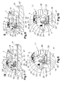
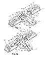
- Figs. 11 to 19 illustrate the application of the mechanism of the invention to the case where a handle (30) is incorporated, comprising an engagement mechanism actuated by means of a cylindrical combination key, as well as an anti-panic push bar (49) and top (51) and bottom (52) locking devices actuated by means of first (44) and second (45) straightedge plates.
- the said actuating means of the carriage (7) comprise a puller (21) which is coupled to the carriage (7) by means of a third track (22), such that its working path and its longitudinal position coincide with the travel length and the front and rear operating positions of the said carriage (7); furthermore, the mechanism according to the invention has a reversible design and construction for left-hand and right-hand doors (47), symmetrical with respect to the longitudinal mid plane of the latch (2), comprising a handle (30), a rotating plate (31), second (32) and third (33) rockers, first (34) and second (35) slide rims, and first (36) and second (37) locks actuated by a key, wherein the rotating plate (31) is rotatably coupled to the handle (30), has a longitudinal convexity (38) towards the floor of the casing (1), has two diametrically opposite leaves (39) that are perpendicular to the said convexity (38) and are capable of adopting two, namely a disengaged and engaged, operating positions of the handle (30), which are
- Fig. 13 the handle (30) is disengaged or in its position closest to the floor of the casing (1), the rockers (32, 33) are in the non-tilting or rest position, the rims (34, 35) are in their position remote from the rotational plate (31), and the straightedge plates (44, 45) are in their extended or most remote position from this plate (31).
- the position of the rims (34, 35) is produced by the action of the eccentric of the corresponding lock (36, 37) in the notch (43), by means of which, when this eccentric is actuated (the upper one in Figs.
- the first rim (34) drops and presses with its edge (42) against the convexity of the plate (31), which reaches its most distant position from the floor of the casing (1) and one of its leaves (39), on rotation of the handle (30), presses against the pivot (40) of the corresponding rocker (32, 33) and ( Figs.
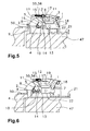
- Another object of the present invention consists in that a first rocker (24), which is rotatably installed on its own rotation shaft (4) of the latch (2), is present in a cavity (23) of the latch (2) open along its longitudinal surface (9), and that in relation to the projecting position of rest of the latch (2), this first rocker (24) has first (25) and second (26) arms that are located respectively outside and inside the casing (1) of the mechanism, and between this first arm (25) and the bottom of the cavity (23) is interposed a second helical spring (27) that has respective compressed and relaxed states in which the first arm (25) remains inside or outside the said cavity (23), and, corresponding to these positions of the first arm (25), a front part (28) of the second arm (26) oriented transversely to the door (47) remains longitudinally opposite, and adjacent or offset with respect to a projection (29) of the casing (1) of the mechanism.
- the device is intended to prevent the catch (2) being able to be released from outside by the conventional method of inserting a credit card or the like between the small gap that always remains between the locked door (47) and its lock frame. If this manoeuvre is attempted ( Figs. 7 and 9 ) the catch (2) cannot move back since the first rocker (24) is tilted against the second helical spring (27) and the front part (28) of the second arm (26) remains bearing against the projection (29) belonging to the casing (1) which is fixed to the door (47).
- the elastic recovery of the second helical spring (27) ( Figs. 8 and 10 ) lifts the first rocker (24) to its rest position, corresponding to that shown in Fig. 4 , in which the latch (2) is available for the manoeuvre of locking the door (47) to its frame.
Landscapes
- Engineering & Computer Science (AREA)
- Mechanical Engineering (AREA)
- Business, Economics & Management (AREA)
- Emergency Management (AREA)
- Lock And Its Accessories (AREA)
- Wing Frames And Configurations (AREA)
Applications Claiming Priority (2)
| Application Number | Priority Date | Filing Date | Title |
|---|---|---|---|
| ES200501577A ES2276598B1 (es) | 2005-06-28 | 2005-06-28 | Mecanismo modular de picaporte de cierre. |
| PCT/ES2006/000328 WO2007000480A1 (es) | 2005-06-28 | 2006-06-05 | Mecanismo modular de picaporte de cierre |
Publications (2)
| Publication Number | Publication Date |
|---|---|
| EP1900894A1 true EP1900894A1 (de) | 2008-03-19 |
| EP1900894A4 EP1900894A4 (de) | 2014-06-25 |
Family
ID=37595053
Family Applications (1)
| Application Number | Title | Priority Date | Filing Date |
|---|---|---|---|
| EP20060778449 Withdrawn EP1900894A4 (de) | 2005-06-28 | 2006-06-05 | Modularer verschlusslaschenmechanismus |
Country Status (8)
| Country | Link |
|---|---|
| US (1) | US20080169655A1 (de) |
| EP (1) | EP1900894A4 (de) |
| KR (1) | KR20080020593A (de) |
| CN (1) | CN101151434B (de) |
| ES (1) | ES2276598B1 (de) |
| MX (1) | MX2007015514A (de) |
| RU (1) | RU2362860C1 (de) |
| WO (1) | WO2007000480A1 (de) |
Cited By (2)
| Publication number | Priority date | Publication date | Assignee | Title |
|---|---|---|---|---|
| FR2993912A1 (fr) * | 2012-07-27 | 2014-01-31 | Thirard Ets | Serrure a plastron d'urgence |
| EP3564467A1 (de) | 2018-05-04 | 2019-11-06 | Groupe Valente | Schliesssystem mit mechanischer verriegelung |
Families Citing this family (10)
| Publication number | Priority date | Publication date | Assignee | Title |
|---|---|---|---|---|
| SE531998C2 (sv) * | 2008-02-01 | 2009-09-22 | Assa Ab | Lås med fallkolv |
| CA2888623C (en) * | 2012-10-19 | 2017-10-10 | Yale Security Inc. | Apparatus and method for electromechanically retracting a door latch |
| US10770836B2 (en) * | 2018-12-17 | 2020-09-08 | Te Connectivity Corporation | Plug connector including a profiled latch |
| US10657795B1 (en) | 2019-02-01 | 2020-05-19 | SimpliSafe, Inc. | Alarm system with first responder code for building access |
| US11761246B2 (en) * | 2019-06-05 | 2023-09-19 | Sargent Manufacturing Company | Surface vertical rod exit device |
| US11933092B2 (en) | 2019-08-13 | 2024-03-19 | SimpliSafe, Inc. | Mounting assembly for door lock |
| CN112431483B (zh) * | 2019-08-26 | 2022-02-22 | 堡笙工业有限公司 | 防盗门锁组 |
| DE202021104902U1 (de) | 2021-09-10 | 2022-12-19 | Baugruppentechnik Pollmeier Gmbh | Türschloss und Falle für ein Türschloss |
| FR3134405B1 (fr) * | 2022-04-12 | 2024-04-12 | La Croisee D S | Dispositif de verrouillage/déverrouillage d’un ouvrant, et ensemble de verrouillage/déverrouillage le comprenant |
| US12595687B2 (en) * | 2024-09-05 | 2026-04-07 | Toby Jack Sims | Panic bar latch system and method |
Family Cites Families (33)
| Publication number | Priority date | Publication date | Assignee | Title |
|---|---|---|---|---|
| US1646990A (en) * | 1925-06-01 | 1927-10-25 | Bolles William Bertram | Antipanic actuator for door fasteners |
| US4427223A (en) * | 1981-08-03 | 1984-01-24 | Von Duprin, Inc. | Latching device |
| US4545606A (en) * | 1983-01-31 | 1985-10-08 | Vodra Richard J | Door latch assembly |
| US4601499A (en) * | 1984-07-03 | 1986-07-22 | Von Duprin, Inc. | Operating mechanism for a closure latching assembly |
| US4741563A (en) * | 1986-04-07 | 1988-05-03 | Von Duprin, Inc. | Center case assembly, and a universal, center case sub-assembly |
| US4796931A (en) * | 1987-08-07 | 1989-01-10 | Yale Security Inc. | Exit device having adjustable backset |
| US4961330A (en) * | 1989-09-12 | 1990-10-09 | Sargent & Greenleaf, Inc. | High security panic exit system |
| US5340171A (en) * | 1992-01-22 | 1994-08-23 | Republic Industries, Inc. | Door latch control apparatus with independent actuators |
| US5412961A (en) * | 1993-06-01 | 1995-05-09 | Von Duprin, Inc. | Exit delaying mechanism for panic exit door |
| US6779819B2 (en) * | 1993-11-01 | 2004-08-24 | Yale Security Inc. | Exit device having press bar-operated elongated securing member |
| CA2134605C (en) * | 1993-11-01 | 1999-01-19 | Walter E. Surko, Jr. | Exit device having a deadbolt as its securing member |
| US5490697A (en) * | 1994-04-12 | 1996-02-13 | International Security Products, Inc. | Access control assembly |
| SE505779C2 (sv) * | 1994-04-14 | 1997-10-06 | Assa Ab | Låsmekanism |
| US5947534A (en) * | 1995-06-19 | 1999-09-07 | Zarzycki, Jr.; Vincent W. | Panic exit device suitable for use with standard doors |
| ES2155291B1 (es) * | 1996-04-01 | 2001-12-01 | Talleres Escoriaza Sa | Barra antipanico con reversibilidad para puertas de emergencia. |
| US6009732A (en) * | 1998-04-07 | 2000-01-04 | Detex Corporation | Panic exit device |
| US6048000A (en) * | 1998-04-28 | 2000-04-11 | Geringer; Arthur | Delayed egress panic device with internal deadlocking bolt mechanism |
| US6032985A (en) * | 1998-05-22 | 2000-03-07 | Harrow Products, Inc. | Latch assembly |
| ES2168171B1 (es) * | 1999-05-13 | 2003-05-01 | Talleres Escoriaza Sa | Dispositivo mejorado para un cierre antipanico |
| ES2217910B1 (es) * | 2001-12-07 | 2005-06-01 | Talleres De Escoriaza, S.A. | Dispositivo para una cerradura antipanico. |
| ITTO20020281A1 (it) * | 2002-03-29 | 2003-09-29 | Savio Spa | ,,sistema di apertura antipanico per porte,,. |
| ITTO20020283A1 (it) * | 2002-03-29 | 2003-09-29 | Savio Spa | ,,dispositivo di regolazione per sistemi di apertura antipanico per porte,,. |
| ES2211277B1 (es) * | 2002-04-10 | 2005-10-01 | La Industrial Cerrajera, S.A. | Cerradura de seguridad con doble control del picaporte y funcion antipanico. |
| TW547534U (en) * | 2002-12-27 | 2003-08-11 | Ching-Tian Lin | Press type door lock device used in fireproof doors |
| TW547533U (en) * | 2002-12-27 | 2003-08-11 | Ching-Tian Lin | Improvement of fireproof door lock structure |
| TW572117U (en) * | 2003-03-17 | 2004-01-11 | Ching-Tian Lin | Fireproof door lock structure |
| TW568161U (en) * | 2003-05-14 | 2003-12-21 | Ching-Tian Lin | Structure of fireproof doors |
| TW568160U (en) * | 2003-05-14 | 2003-12-21 | Ching-Tian Lin | Structure of fireproof doors |
| FR2863000B1 (fr) * | 2003-11-28 | 2007-06-29 | Vachette Sa | Serrure de porte a empennage automatique |
| US7832777B2 (en) * | 2006-04-05 | 2010-11-16 | Von Duprin, Inc. | Door lock assembly |
| US7641244B2 (en) * | 2007-10-24 | 2010-01-05 | Thase Enterprise Co., Ltd. | Fire door lock |
| US7748757B2 (en) * | 2008-09-17 | 2010-07-06 | I-Tek Metal Mfg. Co. Ltd. | Connecting device for concealed-type top or bottom latch for panic exit door lock |
| US7634927B1 (en) * | 2009-02-04 | 2009-12-22 | I-Tek Metal Mfg. Co., Ltd. | Panic exit door lock allowing locking on both sides |
-
2005
- 2005-06-28 ES ES200501577A patent/ES2276598B1/es not_active Expired - Fee Related
-
2006
- 2006-06-05 EP EP20060778449 patent/EP1900894A4/de not_active Withdrawn
- 2006-06-05 RU RU2007137068A patent/RU2362860C1/ru not_active IP Right Cessation
- 2006-06-05 KR KR1020077020290A patent/KR20080020593A/ko not_active Withdrawn
- 2006-06-05 WO PCT/ES2006/000328 patent/WO2007000480A1/es not_active Ceased
- 2006-06-05 US US11/914,229 patent/US20080169655A1/en not_active Abandoned
- 2006-06-05 MX MX2007015514A patent/MX2007015514A/es active IP Right Grant
- 2006-06-05 CN CN200680010632XA patent/CN101151434B/zh active Active
Cited By (3)
| Publication number | Priority date | Publication date | Assignee | Title |
|---|---|---|---|---|
| FR2993912A1 (fr) * | 2012-07-27 | 2014-01-31 | Thirard Ets | Serrure a plastron d'urgence |
| EP3564467A1 (de) | 2018-05-04 | 2019-11-06 | Groupe Valente | Schliesssystem mit mechanischer verriegelung |
| FR3080881A1 (fr) * | 2018-05-04 | 2019-11-08 | Groupe Valente | Systeme de fermeture a verrouillage mecanique |
Also Published As
| Publication number | Publication date |
|---|---|
| WO2007000480A1 (es) | 2007-01-04 |
| ES2276598A1 (es) | 2007-06-16 |
| CN101151434B (zh) | 2012-02-22 |
| EP1900894A4 (de) | 2014-06-25 |
| CN101151434A (zh) | 2008-03-26 |
| MX2007015514A (es) | 2008-03-06 |
| ES2276598B1 (es) | 2008-02-16 |
| KR20080020593A (ko) | 2008-03-05 |
| US20080169655A1 (en) | 2008-07-17 |
| RU2362860C1 (ru) | 2009-07-27 |
Similar Documents
| Publication | Publication Date | Title |
|---|---|---|
| US5953942A (en) | Catch mechanism for locks | |
| EP1900894A1 (de) | Modularer verschlusslaschenmechanismus | |
| JP4538001B2 (ja) | ドアー錠におけるラッチ・ボルトの錠掛けのガイド構造 | |
| JP2554702B2 (ja) | ドアーロック | |
| CN102918220B (zh) | 多重开启门锁机构 | |
| EP0651120A2 (de) | Panikverschluss mit einem Schliessriegel als Sicherheitsvorrichtung | |
| US20060123859A1 (en) | Mortise lock with automatic projection of dead bolt | |
| CN111051631A (zh) | 闩锁装置 | |
| CN108291414A (zh) | 具有锁式致动的连接机构的门或其他可关闭的板体 | |
| CN111386378A (zh) | 一种铰链封闭件 | |
| CN103370488A (zh) | 用于具有防恐慌功能的双门扇门组件的锁系统 | |
| EP1234935A2 (de) | Linearangetriebene Verriegelungsvorrichtung für ein Türsystem eines öffentlichen Transportfahrzeuges | |
| CN1068401C (zh) | 具有紧急开锁功能的门把手总成 | |
| JPH11148258A (ja) | 自己ロック・ダイヤル組合せロック及びロック・システム | |
| EP3853431B1 (de) | Plattenverriegelungsanordnung | |
| CN103827419B (zh) | 闭合和开启系统 | |
| US20240392607A1 (en) | Push Pad Exit Device for Emergency Door Egress and Vertical Latch Bolt Assembly | |
| EP3911821B1 (de) | Plattenverschlussvorrichtung | |
| KR101043620B1 (ko) | 강제해정수단이 구비된 도어용 전자잠금장치 | |
| US7954862B2 (en) | Electromagnetic lock provided with a sliding bolt for a swinging-type door | |
| CN101815835A (zh) | 应急锁 | |
| EP3702558B1 (de) | Gegenschloss für einen inaktiven flügel einer doppelflügeltür | |
| JPH0850836A (ja) | キー操作安全スイッチ | |
| CN108661450A (zh) | 一种带逃生功能安保锁 | |
| WO2006097953A1 (en) | Recessed handle |
Legal Events
| Date | Code | Title | Description |
|---|---|---|---|
| PUAI | Public reference made under article 153(3) epc to a published international application that has entered the european phase |
Free format text: ORIGINAL CODE: 0009012 |
|
| 17P | Request for examination filed |
Effective date: 20080128 |
|
| AK | Designated contracting states |
Kind code of ref document: A1 Designated state(s): AT BE BG CH CY CZ DE DK EE ES FI FR GB GR HU IE IS IT LI LT LU LV MC NL PL PT RO SE SI SK TR |
|
| DAX | Request for extension of the european patent (deleted) | ||
| DAX | Request for extension of the european patent (deleted) | ||
| A4 | Supplementary search report drawn up and despatched |
Effective date: 20140522 |
|
| RIC1 | Information provided on ipc code assigned before grant |
Ipc: E05B 65/10 20060101AFI20140516BHEP |
|
| GRAP | Despatch of communication of intention to grant a patent |
Free format text: ORIGINAL CODE: EPIDOSNIGR1 |
|
| INTG | Intention to grant announced |
Effective date: 20150223 |
|
| GRAS | Grant fee paid |
Free format text: ORIGINAL CODE: EPIDOSNIGR3 |
|
| STAA | Information on the status of an ep patent application or granted ep patent |
Free format text: STATUS: THE APPLICATION IS DEEMED TO BE WITHDRAWN |
|
| 18D | Application deemed to be withdrawn |
Effective date: 20150707 |