EP1900917A2 - Motocyclette - Google Patents
Motocyclette Download PDFInfo
- Publication number
- EP1900917A2 EP1900917A2 EP07253480A EP07253480A EP1900917A2 EP 1900917 A2 EP1900917 A2 EP 1900917A2 EP 07253480 A EP07253480 A EP 07253480A EP 07253480 A EP07253480 A EP 07253480A EP 1900917 A2 EP1900917 A2 EP 1900917A2
- Authority
- EP
- European Patent Office
- Prior art keywords
- width direction
- collecting
- vehicle width
- engine
- exhaust pipes
- Prior art date
- Legal status (The legal status is an assumption and is not a legal conclusion. Google has not performed a legal analysis and makes no representation as to the accuracy of the status listed.)
- Granted
Links
Images






Classifications
-
- F—MECHANICAL ENGINEERING; LIGHTING; HEATING; WEAPONS; BLASTING
- F01—MACHINES OR ENGINES IN GENERAL; ENGINE PLANTS IN GENERAL; STEAM ENGINES
- F01N—GAS-FLOW SILENCERS OR EXHAUST APPARATUS FOR MACHINES OR ENGINES IN GENERAL; GAS-FLOW SILENCERS OR EXHAUST APPARATUS FOR INTERNAL-COMBUSTION ENGINES
- F01N13/00—Exhaust or silencing apparatus characterised by constructional features
- F01N13/008—Mounting or arrangement of exhaust sensors in or on exhaust apparatus
-
- F—MECHANICAL ENGINEERING; LIGHTING; HEATING; WEAPONS; BLASTING
- F01—MACHINES OR ENGINES IN GENERAL; ENGINE PLANTS IN GENERAL; STEAM ENGINES
- F01N—GAS-FLOW SILENCERS OR EXHAUST APPARATUS FOR MACHINES OR ENGINES IN GENERAL; GAS-FLOW SILENCERS OR EXHAUST APPARATUS FOR INTERNAL-COMBUSTION ENGINES
- F01N13/00—Exhaust or silencing apparatus characterised by constructional features
- F01N13/009—Exhaust or silencing apparatus characterised by constructional features having two or more separate purifying devices arranged in series
- F01N13/0097—Exhaust or silencing apparatus characterised by constructional features having two or more separate purifying devices arranged in series the purifying devices are arranged in a single housing
-
- F—MECHANICAL ENGINEERING; LIGHTING; HEATING; WEAPONS; BLASTING
- F01—MACHINES OR ENGINES IN GENERAL; ENGINE PLANTS IN GENERAL; STEAM ENGINES
- F01N—GAS-FLOW SILENCERS OR EXHAUST APPARATUS FOR MACHINES OR ENGINES IN GENERAL; GAS-FLOW SILENCERS OR EXHAUST APPARATUS FOR INTERNAL-COMBUSTION ENGINES
- F01N13/00—Exhaust or silencing apparatus characterised by constructional features
- F01N13/011—Exhaust or silencing apparatus characterised by constructional features having two or more purifying devices arranged in parallel
-
- F—MECHANICAL ENGINEERING; LIGHTING; HEATING; WEAPONS; BLASTING
- F01—MACHINES OR ENGINES IN GENERAL; ENGINE PLANTS IN GENERAL; STEAM ENGINES
- F01N—GAS-FLOW SILENCERS OR EXHAUST APPARATUS FOR MACHINES OR ENGINES IN GENERAL; GAS-FLOW SILENCERS OR EXHAUST APPARATUS FOR INTERNAL-COMBUSTION ENGINES
- F01N13/00—Exhaust or silencing apparatus characterised by constructional features
- F01N13/08—Other arrangements or adaptations of exhaust conduits
- F01N13/10—Other arrangements or adaptations of exhaust conduits of exhaust manifolds
-
- F—MECHANICAL ENGINEERING; LIGHTING; HEATING; WEAPONS; BLASTING
- F01—MACHINES OR ENGINES IN GENERAL; ENGINE PLANTS IN GENERAL; STEAM ENGINES
- F01N—GAS-FLOW SILENCERS OR EXHAUST APPARATUS FOR MACHINES OR ENGINES IN GENERAL; GAS-FLOW SILENCERS OR EXHAUST APPARATUS FOR INTERNAL-COMBUSTION ENGINES
- F01N13/00—Exhaust or silencing apparatus characterised by constructional features
- F01N13/18—Construction facilitating manufacture, assembly, or disassembly
- F01N13/1805—Fixing exhaust manifolds, exhaust pipes or pipe sections to each other, to engine or to vehicle body
- F01N13/1811—Fixing exhaust manifolds, exhaust pipes or pipe sections to each other, to engine or to vehicle body with means permitting relative movement, e.g. compensation of thermal expansion or vibration
- F01N13/1822—Fixing exhaust manifolds, exhaust pipes or pipe sections to each other, to engine or to vehicle body with means permitting relative movement, e.g. compensation of thermal expansion or vibration for fixing exhaust pipes or devices to vehicle body
-
- F—MECHANICAL ENGINEERING; LIGHTING; HEATING; WEAPONS; BLASTING
- F01—MACHINES OR ENGINES IN GENERAL; ENGINE PLANTS IN GENERAL; STEAM ENGINES
- F01N—GAS-FLOW SILENCERS OR EXHAUST APPARATUS FOR MACHINES OR ENGINES IN GENERAL; GAS-FLOW SILENCERS OR EXHAUST APPARATUS FOR INTERNAL-COMBUSTION ENGINES
- F01N3/00—Exhaust or silencing apparatus having means for purifying, rendering innocuous, or otherwise treating exhaust
- F01N3/08—Exhaust or silencing apparatus having means for purifying, rendering innocuous, or otherwise treating exhaust for rendering innocuous
- F01N3/10—Exhaust or silencing apparatus having means for purifying, rendering innocuous, or otherwise treating exhaust for rendering innocuous by thermal or catalytic conversion of noxious components of exhaust
- F01N3/24—Exhaust or silencing apparatus having means for purifying, rendering innocuous, or otherwise treating exhaust for rendering innocuous by thermal or catalytic conversion of noxious components of exhaust characterised by constructional aspects of converting apparatus
- F01N3/28—Construction of catalytic reactors
- F01N3/2882—Catalytic reactors combined or associated with other devices, e.g. exhaust silencers or other exhaust purification devices
- F01N3/2885—Catalytic reactors combined or associated with other devices, e.g. exhaust silencers or other exhaust purification devices with exhaust silencers in a single housing
-
- F—MECHANICAL ENGINEERING; LIGHTING; HEATING; WEAPONS; BLASTING
- F01—MACHINES OR ENGINES IN GENERAL; ENGINE PLANTS IN GENERAL; STEAM ENGINES
- F01N—GAS-FLOW SILENCERS OR EXHAUST APPARATUS FOR MACHINES OR ENGINES IN GENERAL; GAS-FLOW SILENCERS OR EXHAUST APPARATUS FOR INTERNAL-COMBUSTION ENGINES
- F01N13/00—Exhaust or silencing apparatus characterised by constructional features
- F01N13/08—Other arrangements or adaptations of exhaust conduits
-
- F—MECHANICAL ENGINEERING; LIGHTING; HEATING; WEAPONS; BLASTING
- F01—MACHINES OR ENGINES IN GENERAL; ENGINE PLANTS IN GENERAL; STEAM ENGINES
- F01N—GAS-FLOW SILENCERS OR EXHAUST APPARATUS FOR MACHINES OR ENGINES IN GENERAL; GAS-FLOW SILENCERS OR EXHAUST APPARATUS FOR INTERNAL-COMBUSTION ENGINES
- F01N2340/00—Dimensional characteristics of the exhaust system, e.g. length, diameter or volume of the exhaust apparatus; Spatial arrangements of exhaust apparatuses
- F01N2340/04—Arrangement of the exhaust system relative to a vehicle or parts thereof
-
- F—MECHANICAL ENGINEERING; LIGHTING; HEATING; WEAPONS; BLASTING
- F01—MACHINES OR ENGINES IN GENERAL; ENGINE PLANTS IN GENERAL; STEAM ENGINES
- F01N—GAS-FLOW SILENCERS OR EXHAUST APPARATUS FOR MACHINES OR ENGINES IN GENERAL; GAS-FLOW SILENCERS OR EXHAUST APPARATUS FOR INTERNAL-COMBUSTION ENGINES
- F01N2470/00—Structure or shape of exhaust gas passages, pipes or tubes
-
- F—MECHANICAL ENGINEERING; LIGHTING; HEATING; WEAPONS; BLASTING
- F01—MACHINES OR ENGINES IN GENERAL; ENGINE PLANTS IN GENERAL; STEAM ENGINES
- F01N—GAS-FLOW SILENCERS OR EXHAUST APPARATUS FOR MACHINES OR ENGINES IN GENERAL; GAS-FLOW SILENCERS OR EXHAUST APPARATUS FOR INTERNAL-COMBUSTION ENGINES
- F01N2590/00—Exhaust or silencing apparatus adapted to particular use, e.g. for military applications, airplanes, submarines
- F01N2590/04—Exhaust or silencing apparatus adapted to particular use, e.g. for military applications, airplanes, submarines for motorcycles
-
- Y—GENERAL TAGGING OF NEW TECHNOLOGICAL DEVELOPMENTS; GENERAL TAGGING OF CROSS-SECTIONAL TECHNOLOGIES SPANNING OVER SEVERAL SECTIONS OF THE IPC; TECHNICAL SUBJECTS COVERED BY FORMER USPC CROSS-REFERENCE ART COLLECTIONS [XRACs] AND DIGESTS
- Y02—TECHNOLOGIES OR APPLICATIONS FOR MITIGATION OR ADAPTATION AGAINST CLIMATE CHANGE
- Y02A—TECHNOLOGIES FOR ADAPTATION TO CLIMATE CHANGE
- Y02A50/00—TECHNOLOGIES FOR ADAPTATION TO CLIMATE CHANGE in human health protection, e.g. against extreme weather
- Y02A50/20—Air quality improvement or preservation, e.g. vehicle emission control or emission reduction by using catalytic converters
Definitions
- the present invention relates to a motorcycle including an exhaust system connected to an engine.
- Patent Document 1 adopts a structure in which four exhaust pipes connected to the front wall of a cylinder head are extended downward from the front wall and bent rearward so as to pass through a portion below an engine, and in the portion below the engine, the respective exhaust pipes are moved toward the side where a muffler is arranged and are collected together at a collecting portion, and the muffler is connected to the collecting portion.
- the exhaust pipes, the collecting portion, and the muffler are concentrated on one side in the vehicle width direction, which may impair the weight balance with respect to the vehicle width direction.
- the present invention seeks to provide a motorcycle which makes it possible to achieve a good weight balance with respect to the vehicle width direction when a plurality of exhaust pipes are collected together and connected to a single muffler.
- An embodiment of the invention provides a motorcycle including a body frame, an engine mounted to the body frame, and an exhaust system connected to the engine, in which: the exhaust system includes a plurality of exhaust pipes connected to a front wall of the engine and extending rearward while passing below the engine, a collecting portion where the plurality of exhaust pipes are collected together, and a muffler connected to the collecting portion; and as seen from the front of the vehicle, the plurality of exhaust pipes extend from the front wall of the engine rearward on one side in a vehicle width direction and so as to pass below the engine, and are connected to the collecting portion, and the muffler is arranged on the other side in the vehicle width direction and connected to the collecting portion.
- the plurality of exhaust pipes connected to the front wall of the engine are extended from the front wall rearward on one side in the vehicle width direction and below the engine and are connected to the collecting portion, and the collecting portion is connected to the muffler arranged on the other side in the vehicle width direction. Accordingly, when seen as a whole, the respective exhaust pipes are positioned so as to be displaced to one side in the vehicle width direction. On the other hand, the muffler is positioned so as to be displaced to the other side in the vehicle width direction.
- the plurality of exhaust pipes and the muffler that are heavy-weight objects can be thus arranged in good balance on one side and on the other side in the vehicle width direction.
- the plurality of exhaust pipes are positioned on one side in the vehicle width direction, and the muffler is positioned on the other side. This gives an element of flow and motion to the design of the exhaust system, thereby making it possible to achieve enhanced marketability in appearance.
- FIGs . 1 to 11 are views illustrating an exhaust system of a motorcycle according to an embodiment of the present invention.
- the terms front and rear as used in this embodiment means the front and rear as viewed by the rider seated on the seat, and the terms left and right means the left and right as viewed from the front of the vehicle.
- reference numeral 1 denotes a motorcycle.
- the motorcycle 1 includes a double-cradle type body frame 2, an engine 3 mounted inside the cradle of the body frame 2, and an intake system 4 and an exhaust system 5 that are connected to the engine 3.
- a front fork 7 is supported by a head pipe 6 arranged at the front end of the body frame 2 so as to be steerable to the left and right.
- a front wheel 8 and a steering handlebar 9 are respectively arranged at the lower and upper end portions of the front fork 7.
- the front end portion of a rear arm 10 is supported by a rear portion of the body frame 2 so as to be vertically swingable.
- a rear wheel 11 is arranged at the rear end portion of the rear arm 10.
- a fuel tank 14 is arranged above the engine 3 in the body frame 2, and a seat 15 is arranged on the rear side of the fuel tank 14.
- the body frame 2 includes left and right frame members 2a, 2a, and upper and lower cross members 20, 21 made of steel pipes that connect the rear end portions of the left and right frame members 2a to each other.
- the left and right frame members 2a are substantially laterally symmetrical.
- the left and right frame members 2a include left and right upper tubes 16, 16, which have tank rail portions 16a, 16a extending slightly downward to the rear from an upper portion of the head pipe 6 and rear-arm supporting portions 16b, 16b extending rearwardly downward from the rear ends of the tank rail portions 16a, and left and right down tubes 17, 17, which have inclined portions 17a, 17a extending obliquely downward to the rear from a lower portion of the head pipe 6 and horizontal portions 17b, 17b extending substantially horizontally to the rear from the lower ends of the inclined portions 17a.
- left and right frame members 2a, 2a include left and right seat rails 18, 18 extending obliquely upward to the rear from the upper end portions of the left and right rear-arm supporting portions 16b, and left and right seat stays 19, 19 that connect between longitudinally midway portions of the seat rails 18 and lower portions of the rear-arm supporting portions 16b.
- the upper cross member 20 is arranged in each of the vertically halfway portions of the left and right rear-arm supporting portions 16b, 16b.
- the lower cross member 21 is arranged at the connecting portion between the lower end portion of each of the left and right rear-arm supporting portions 16b, and the rear end portion of each of the left and right horizontal portions 17b.
- the engine 3 is a water-cooled four-cycle, parallel four-cylinder engine.
- the engine 3 is mounted with the cylinder axis tilted forward, and is suspended and supported by the left and right upper tubes 16 and the left and right down tubes 17.
- the engine 3 has a structure in which a cylinder block 27, a cylinder head 28, and a head cover 29 are stacked in order on the upper mating surface of a crankcase 26 in which a crankshaft 25 is accommodated, a transmission case 26a in which a transmission mechanism (not shown) is accommodated is integrally formed and connected to a rear portion of the crankcase 26, and an oil sump 30 is connected to the bottom portion of the crankcase 26.
- Generally triangular rear-arm brackets 32, 32 are connected on the front side of the left and right rear-arm supporting portions 16b so as to be positioned inside the cradle.
- the rear arm 10 is supported by the left and right rear-arm supporting brackets 32 via a pivot shaft 33.
- footrests 34, 34 on which the rider places his/her feet are arranged so as to project outward in the vehicle width direction.
- the front end portions of generally triangular foot brackets 35, 35 that extend rearward are connected to the left and right seat stays 19.
- a tandem footrest 36 on which the passenger in the rear portion places his/her feet is arranged at the rear end portion of each of the foot brackets 35.
- a downwardly C-shaped stand bracket 37 that extends downward is connected to the lower cross member 21.
- a main stand 38 is arranged in the stand bracket 37 so as to be pivotable between an upright position in which the main stand 38 holds the vehicle body, and a retracted position in which the main stand 38 is substantially in parallel to the horizontal portions 17b of the down tubes 17.
- the main stand 38 includes a stand body 38b having left and right leg portions 38a, 38a, and a footstep arm portion 38c formed so as to extend to the outside of the vehicle from the leg portion 38a on the right side.
- the intake system 4 includes four intake pipes 40 connected to a rear wall 28a of the cylinder head 28 for respective cylinders, a throttle body 41 connected to each intake pipe 40, and a common air cleaner connected to each throttle body 41.
- a fuel injection valve 45 for injecting fuel to supply into an intake port (not shown) formed in the cylinder head 28 is fitted to the downstream end portion of each of the intake pipes 40.
- the exhaust system 5 includes first to fourth exhaust pipes 50, 51, 52, 53, which are connected to exhaust ports formed in a front wall 28b of the cylinder head 28 for respective cylinders and extend downward from the front wall 28b and then extends rearward while passing below the engine 3, a right-side collecting portion (first collecting portion) where the first and second exhaust pipes (first exhaust pipe group) 50, 51 are collected together, a left-side collecting portion (second collecting portion) where the third and fourth exhaust pipes (second exhaust pipe group) 52, 53 are collected together, a main collecting portion (third collecting portion) 56 where the left-side and right-side collecting portions 54, 55 are collected together, and a single muffler 57 connected to a rearwardly extended portion 56b of the main collecting portion 56.
- the first to fourth exhaust pipes 50 to 53, the right-side and left-side collecting portions 54, 55, and the main collecting portion 56 are joined integrally by welding.
- the muffler 57 is detachably connected to the rearwardly extended portion 56b of the main collecting portion 56 by a band member 47.
- Upstream-side catalysts (first catalyst) 48, 48 for performing purification of an exhaust gas are arranged inside the right-side and left-side collecting portions 54, 55.
- a downstream-side catalyst (second catalyst) 49 for performing purification of an exhaust gas is arranged inside the muffler 57.
- the muffler 57 is arranged so as to be oriented obliquely upward on the left side (other side) in the vehicle width direction of the rear wheel 11. As seen in plan view, the muffler 57 has a cylindrical rear-side muffler portion 57b that extends substantially in parallel to the vehicle body centerline C, and a substantially conical front-side muffler portion 57c that extends from the front end of the rear-side muffler portion 57b so as to be bent toward the vehicle body centerline C.
- the muffler 57 is located within the projection plane of the rear wheel 11.
- the catalyst 49 is arranged at the boundary between the front-side and rear-side muffler portions 57c, 57b.
- a mounting strip 57a is formed in the upper wall of the rear-side muffler portion 57b of the muffler 57 so as to project upward.
- the mounting strip 57a is mounted and fixed on the rear side of the tandem footrest 36 of the left foot bracket 35.
- a flat mounting bracket 58 is connected to the right-side and left-side collecting portions 54, 55 so as to bridge the upper ends of the respective collecting portions 54, 55.
- a mounting hole 58a is formed in the mounting bracket 58 so as to be positioned between the two collecting portions 55, 54.
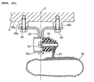
- FIG. 9 is a cross-sectional view of the right-side and left-side collecting portions 54, 55 as seen from the rear of the vehicle.
- a grommet 59 is fitted onto the mounting hole 58a.
- a boss portion 30a is formed at the bottom portion of the oil sump 30.
- the mounting bracket 58 is mounted to the boss portion 30a through the intermediation of the grommet 59 by means of a bolt 60 that is inserted from below.
- the right-side and left-side collecting portions 54, 55 are thus elastically supported on the oil sump 30.
- a mounting bracket 61 is connected to the upstream-side end portion of the main collecting portion 56 so as to project upward. Further, a pair of left and right boss portions 26b, 26b are formed at the bottom portion of the transmission case 26a of the crankcase 26.
- a substantially T-shaped stay 62 is fixed to the respective boss portions 26b by means of bolts 63, 63 that are threadedly inserted from below.
- a cylinder member 62a is arranged in and fixed to the stay 62 with its axis oriented in the vehicle width direction.
- a grommet 64 is inserted and fixed inside the cylinder member 62a.
- the mounting bracket 61 is mounted to the stay 62 via the grommet 64 by means of a bolt 65 inserted in the vehicle width direction.
- the main collecting portion 56 is thus elastically supported on the crankcase 26.
- the right-side collecting portion 54 has a bifurcated connecting portion 54a to which the first and second exhaust pipes 50, 51 are connected, a small-diameter portion 54b continuous to the connecting portion 54a and formed so as to have a smaller passage area, and a large-diameter portion 54c continuous to the small-diameter portion 54b and formed so as to have a larger passage area.
- the catalyst 48 is arranged in the large-diameter portion 54c.
- the left-side collecting portion 55 has a bifurcated connecting portion 55a to which the third and fourth exhaust pipes 52, 53 are connected, a small-diameter portion 55b, and a large-diameter portion 55c.
- the catalyst 48 is arranged in the large-diameter portion 55c.
- the right-side and left-side collecting portions 54, 55 are displaced to the right side in the vehicle width direction with respect to a vehicle body centerline C. That is, with the left-side and right-side collecting portions 54, 55 seen as a single mass, its center is displaced to the right side in the vehicle width direction. It should be noted that the centerline of the engine 3 in the vehicle width direction coincides with the vehicle body centerline C.
- the connecting portion 54a of the right-side collecting portion 54 is displaced to the right side in the vehicle width direction with respect to the vehicle body centerline C and arranged in proximity to the right down tube 17.
- the small-diameter portion 54b is formed so as to be bent in a L shape to the left side in the vehicle width direction from the connecting portion 54a.
- the downstream-side end portion of the large-diameter portion 54c is in proximity to the vehicle body centerline C.
- the connecting portion 55a of the left-side collecting portion 55 is arranged such that its center substantially coincides with the vehicle body centerline C.
- the small-diameter portion 55b is formed so as to be bent in a L shape to the left side in the vehicle width direction on the vehicle body centerline C.
- the large-diameter portion 55c is arranged with its inner end portion overlapping the vehicle body centerline C. In other words, the large-diameter portions 54c, 55c of the right-side and left-side collecting portions 54, 55 are displaced to the left side in the vehicle width direction with respect to the connecting portions 54a, 55a.
- the main collecting portion 56 is arranged so as to be positioned on the left side in the vehicle width direction with respect to the vehicle body centerline C.
- the main collecting portion 56 has a bifurcated connecting portion 56a to which the right-side and left-side collecting portions 54, 55 are connected, and the rearwardly extended portion (inclined portion) 56b.
- the rearwardly extended portion 56b extends in a substantially linear fashion obliquely outward to the left from the connecting portion 56a and, as seen from the lateral side, extends obliquely upward.
- the rearwardly extended portion 56b extends rearward so as to pass through a space between the left-side footrest 34 and the main stand 38, from a position in rear of the engine 3 and below the lower cross member 21.
- the muffler 57 is connected to the rear end portion of the rearwardly extended portion 56b.
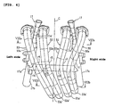
- the first to fourth exhaust pipes 50 to 53 has front-side exhaust pipe portions 50a to 53a that extend obliquely downward from first to fourth exhaust ports in the front wall 28b of the cylinder head 28 toward the right side (one side) in the vehicle width direction, and rear-side exhaust pipe portions 50b to 53b that extend rearward from the lower end portions of the front-side exhaust pipe portions 50a to 53a while being bent so as to pass below the oil sump 30 of the engine 3.
- the detailed structure of the first to fourth exhaust pipes 50 to 53 is as described below.
- the right down tube 17 is positioned between the first and second exhaust pipes 50, 51, and the left down tube 17 is positioned between the third and fourth exhaust pipes 52, 53.
- the vehicle body centerline C is positioned at substantially the middle in the vehicle width direction between the second and third exhaust pipes 51, 52.
- the first to fourth front-side exhaust pipe portions 50a to 53a are positioned forward of the inclined portions 17a of the left and right down tubes 17, and crossing portions 17a' of the left and right inclined portions 17a with the front-side exhaust pipe portions 50a to 53a have an elliptic cross section crushed in the vehicle width direction (see FIG. 4). This prevents interference from occurring as the inclined portions 17a, 17a of the down tubes 17 pass between the respective front-side exhaust pipe portions 50a, 51a and 52a, 53a.
- the first and second rear-side exhaust pipe portions 50b, 51b extend linearly to the rear while in contact with each other from the lower end portions of the front-side exhaust pipe portions 50a, 51a and are connected to the right-side collecting portion 54.
- the third and fourth rear-side exhaust pipe portions 52b, 53b are connected while in contact with each other to the left-side collecting portion 55.
- the first and second front-side exhaust pipe portions 50a, 51a first extend obliquely downward to the inner side toward the vehicle body centerline C from the connecting portions with the exhaust ports, that is, from the upstream end portions, and then extend obliquely downward while being bent to the outer side at bending R portions r1, r2.
- the first and second front-side exhaust pipe portions 50a, 51a are thus generally shaped in a L shape as a whole.
- the third and fourth front-side exhaust pipe portions 52a, 53a extend obliquely downward from their upstream end portions toward the vehicle body centerline C while being gently curved at bending R portions r3, r4.
- the lower end portion of the third front-side exhaust pipe portion 52a extends to the right side in the vehicle width direction beyond the vehicle body centerline C, and the lower end portion of the fourth front-side exhaust pipe portion 53a extends so as to overlap the vehicle body centerline C.
- each of the bending R portions r1, r2, r3, r4 has a center of curvature positioned on one side (right side) in the vehicle width direction with respect to the center of each of the front-side exhaust pipes, and is thus bent so as to be convex facing toward the other side in the vehicle width direction.
- the radii of the bending R's of the bending R portions r1, r2 of the first and second front-side exhaust pipe portions 50a, 51a are set to values smaller than the radii of the bending R' s of the bending R portions r3, r4 of the third and fourth front-side exhaust pipe portions 52a, 53a (see Figs. 4, 5).
- top portions c3, c4 of the bending R's of the bending R portions r3, r4 of the third and fourth front-side exhaust pipe portions 52a, 53a are positioned higher than top portions c1, c2 of the bending R' s of the bending R portions r1, r2 of the first and second front-side exhaust pipe portions 50a, 51a.
- each of the first to fourth front-side exhaust pipe portions 50a to 53a with respect to the bending R portions r1 to r4 have the following structure.
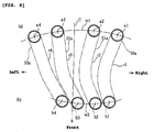
- the centers a1 to a4 of the first to fourth front-side exhaust pipe portions 50a to 53a in the upstream-side portion are arranged so as to diverge toward the front of the vehicle as a whole.
- a curve w1 connecting the centers a1 to a4 is convex facing toward the rear of the vehicle.
- the centers b1 to b4 of the first to fourth front-side exhaust pipe portions 50a to 53a in the downstream-side portion are arranged so as to converge toward the front of the vehicle as a whole.
- a curve w2 connecting the centers b1 to b4 is convex facing toward the front of the vehicle.
- the second and third front-side exhaust pipe portions 51a, 52a are positioned on the rear side with respect to the first and fourth front-side exhaust pipe portions 50a, 53a, and in the downstream-side portion, the second and third front-side exhaust pipe portions 51a, 52a are positioned on the front side with respect to the first and fourth front-side exhaust pipe portions 50a, 53a.
- rearwardly bent portions 50a', 51a' at the lower ends of the first and second front-side exhaust pipe portions 50a, 51a are formed on the outer side in the vehicle width direction with respect to, and positioned higher than, rearwardly bent portions 52a', 53a' at the lower ends of the third and fourth front-side exhaust pipe portions 52a, 53a. Further, the rearwardly bent portion 50a' of the first front-side exhaust pipe portion 50a is formed so as to be positioned higher than the rearwardly bent portion 51a' of the second front-side exhaust pipe portion 51a (see FIG. 4).
- the first and second rear-side exhaust pipe portions 50b, 51b are arranged at positions higher than the third and fourth rear-side exhaust pipe portions 52b, 53b, and further the first rear-side exhaust pipe portion 50b is arranged at a position higher than the second rear-side exhaust pipe portion 51b.
- the bank angle becomes large as a result.
- the exhaust system 5 includes an exhaust valve 67.
- the exhaust valve 67 is arranged at the downstream-side end portion of the rearwardly extended portion 56b of the main collecting portion 56 and on the upstream side of the downstream-side catalyst 49, and is formed by arranging a valve plate 67b, which causes the passage area inside the main collecting portion 56 to change, on a valve shaft 67a that radially extends through the main collecting portion 56 (see FIG. 7).
- the valve shaft 67a is arranged in a titled manner so that its position is higher on the outer side in the vehicle width direction.
- a drive cable (not shown) is connected to the valve shaft 67a.
- the exhaust system 5 has an oxygen concentration sensor 68 that detects the concentration of oxygen in an exhaust gas.
- An air fuel ratio is found on the basis of the oxygen concentration detected by the oxygen concentration sensor 68, and the amount of fuel supply from the fuel injection valve 45 is controlled so that this air-fuel ratio becomes a target air-fuel ratio.
- the oxygen concentration sensor 68 has a detecting portion 68a inserted with its distal end portion positioned inside the rearwardly extended portion 56b of the main collecting portion 56, a sensor body 68b connected to the detecting portion 68a, and an external connection cable 68c for leading a detection signal to the outside from the detecting portion 68a (see FIG. 11).
- a sensor fitting hole 56d is formed in the rearwardly extended portion 56b of the main collecting portion 56.
- a nut member 69 is connected to the fitting hole 56d in an airtight manner.
- the oxygen concentration sensor 68 is detachably mounted to the main collecting portion 56 by fastening and fixing the sensor body 68b to the nut member 69 in an airtight manner.
- the oxygen concentration sensor 68 is arranged in an upper wall portion 56e of the rearwardly extended portion 56b of the main collecting portion 56, and on the upstream side in front of the exhaust valve 67.
- the oxygen concentration sensor 68 thus detects the concentration of oxygen in the exhaust gas that has passed through each of the left and right upstream-side catalysts 48, 48.
- the oxygen concentration sensor 68 is arranged in a tilted manner so that the upper portion of the sensor body 68b is positioned on the inner side in the vehicle width direction and upward. Further, as seen in the longitudinal direction of the vehicle, the oxygen concentration sensor 68 is arranged so as to cross the exhaust valve 67.
- the oxygen concentration sensor 68 is arranged between the engine 3 and the rear wheel 11, and so as to be positioned substantially at the same height as the lower cross member 21.
- the oxygen concentration sensor 68 is arranged so as to be positioned above the main stand 38 that is in the retracted position, positioned below the rear arm 10 and on its outer side in the vehicle width direction, and positioned on the inner side in the vehicle width direction of the footrest 34 on the left side.
- the oxygen concentration sensor 68 is surrounded by the lower cross member 21, the stand bracket 37, the stand body 38b, the footstep arm portion 38c, the rear-arm supporting portion 16b, and the rear arm 10.
- the four exhaust pipes, the first to fourth exhaust pipes 50 to 53 connected to the exhaust ports of the respective cylinders in the front wall 28b of the cylinder head 28 are extended from the rear wall 28b obliquely downward to the right side in the vehicle width direction and are connected to the right-side and left-side collecting portions 54, 55 that are displaced to this right side, and the right-side and left-side collecting portions 54, 55 are connected via the main collecting portion 56 to the single muffler 57 that is displaced to the left side in the vehicle width direction.
- the first to fourth exhaust pipes 50 to 53 and the left-side and right-side collecting portions 54, 55 are positioned on the right side in the vehicle width direction, and the muffler 57 is positioned on the left side in the vehicle width direction, with respect to the vehicle body centerline C.
- the exhaust pipes and the muffler, which are heavy-weight objects in the exhaust system 5 can be thus laid out with good balance on the left and right, thereby achieving good weight balance with respect to the vehicle width direction.
- the first to fourth exhaust pipes 50 to 53 are tilted obliquely downward toward the right side from the front wall 28b. Therefore, the exhaust pipes are enlarged in length as compared with a case where, for example, the exhaust pipes are extended vertically downward, thereby making it possible to secure a required exhaust pipe length and an improvement in output performance.
- the first to four exhaust pipes 50 to 53 are first displaced toward the right side and connected to the right-side and left-side collecting portions 54, 55 arranged so as to be displaced to this right side, and are then connected via the main collecting portion 56 to the muffler 57 arranged so as to be displaced to the opposite side (left side).
- the left and right collecting portions 54, 55 are arranged so as to be displaced to one side in the vehicle width direction, this means that when the collecting portions 54, 55 are seen as a single mass, its center is displaced to one side in the vehicle width direction.
- the exhaust pipe lengths of the respective exhaust pipes 50 to 53 can be made substantially same. That is, since the first and second exhaust pipes 50, 51 have a generally curved shape, and the third and fourth exhaust pipes 52, 53 have a generally linear shape, it is possible to reduce the difference in exhaust pipe length between the first and second exhaust pipes 50, 51 and the third and fourth exhaust pipes 52, 53.
- the radius of the bending R differs between the bending R portions r1, r2 of the first and second exhaust pipes 50, 51 and the bending R portions r3, r4 of the third and fourth exhaust pipes 52, 53, the feel of a smooth curve with little or no linear section, that is, a hand-bent or hand-made feel can be given. Enhanced marketability in appearance can be achieved also in this respect.
- the curve w1 in the upstream-side portions of the first to fourth exhaust pipes 50 to 53 with respect to the bending R portions r1 to r4 is formed in a convex shape facing toward the rear of the vehicle, and the curve w2 in the downstream-side portions is formed in a convex shape facing toward the front of the vehicle.
- the above-mentioned hand-bent feel can be given also in this respect.
- the right-side and left-side collecting portions 54, 55 are supported by the oil sump 30 via the mounting bracket 58, thereby achieving increased reliability in terms of the supporting strength for the right-side and left-side collecting portions 54, 55 that are heavy-weight objects.
- the front end portion of the main collecting portion 56 is supported by the transmission case 26a of the crankcase 26 via the mounting bracket 61, thereby achieving increased reliability in terms of the supporting strength for the main collecting portion 56 that is a heavy-weight object.
- the portions on the front side and rear side of the catalysts 48 arranged in the left-side and right-side collecting portions 54, 55 are supported by the engine 3 via the mounting brackets 58, 61, respectively, thereby achieving a further increase in reliability in terms of supporting strength.
- the description is directed to the case where the number of exhaust pipes is four
- the exhaust system according to the present invention is also applicable to a case where the number of exhaust pipes is three or five.
- the same effect as that of the above embodiment can be obtained by arranging the exhaust pipes so as to be displaced to one side in the vehicle width direction.
Landscapes
- Engineering & Computer Science (AREA)
- Chemical & Material Sciences (AREA)
- Combustion & Propulsion (AREA)
- Mechanical Engineering (AREA)
- General Engineering & Computer Science (AREA)
- Chemical Kinetics & Catalysis (AREA)
- Analytical Chemistry (AREA)
- Health & Medical Sciences (AREA)
- Toxicology (AREA)
- Exhaust Silencers (AREA)
- Automatic Cycles, And Cycles In General (AREA)
- Axle Suspensions And Sidecars For Cycles (AREA)
Applications Claiming Priority (1)
| Application Number | Priority Date | Filing Date | Title |
|---|---|---|---|
| JP2006249222A JP4745179B2 (ja) | 2006-09-14 | 2006-09-14 | 自動二輪車 |
Publications (3)
| Publication Number | Publication Date |
|---|---|
| EP1900917A2 true EP1900917A2 (fr) | 2008-03-19 |
| EP1900917A3 EP1900917A3 (fr) | 2009-09-02 |
| EP1900917B1 EP1900917B1 (fr) | 2011-02-09 |
Family
ID=38738884
Family Applications (1)
| Application Number | Title | Priority Date | Filing Date |
|---|---|---|---|
| EP07253480A Active EP1900917B1 (fr) | 2006-09-14 | 2007-09-03 | Motocyclette |
Country Status (4)
| Country | Link |
|---|---|
| EP (1) | EP1900917B1 (fr) |
| JP (1) | JP4745179B2 (fr) |
| AT (1) | ATE498057T1 (fr) |
| DE (1) | DE602007012392D1 (fr) |
Cited By (3)
| Publication number | Priority date | Publication date | Assignee | Title |
|---|---|---|---|---|
| GR20080100358A (el) * | 2008-05-27 | 2009-12-31 | Honda Motor Co., Ltd. | Συστημα εξατμισης μοτοσικλετας |
| CN103352747A (zh) * | 2013-06-28 | 2013-10-16 | 安徽江淮汽车股份有限公司 | 汽车排气管与收烟罩间连接装置 |
| WO2022106037A1 (fr) * | 2020-11-23 | 2022-05-27 | Piaggio & C. S.P.A | Système de gaz d'échappement pour une motocyclette |
Families Citing this family (3)
| Publication number | Priority date | Publication date | Assignee | Title |
|---|---|---|---|---|
| JP5414330B2 (ja) * | 2009-03-31 | 2014-02-12 | 本田技研工業株式会社 | 鞍乗り型車両 |
| US8359847B2 (en) | 2009-10-01 | 2013-01-29 | Albert Earl Hatchett | Device and method for converting a motorcycle exhaust system into a multiple exhaust system |
| JP6845880B2 (ja) * | 2019-02-25 | 2021-03-24 | 本田技研工業株式会社 | 鞍乗り型車両の排気構造 |
Citations (1)
| Publication number | Priority date | Publication date | Assignee | Title |
|---|---|---|---|---|
| US20020050415A1 (en) | 2000-10-30 | 2002-05-02 | Suzuki Kabushiki Kaisha | Exhaust system of motorcycle |
Family Cites Families (6)
| Publication number | Priority date | Publication date | Assignee | Title |
|---|---|---|---|---|
| JPS5817219U (ja) * | 1981-07-29 | 1983-02-02 | スズキ株式会社 | エンジンの排気チヤンバ−取着装置 |
| JPS5943616U (ja) * | 1982-09-13 | 1984-03-22 | スズキ株式会社 | エンジンのマフラプレチヤンバ− |
| DE69213780T2 (de) * | 1991-02-22 | 1997-01-30 | Yamaha Motor Co Ltd | Motorrad mit Abgasvorrichtung |
| JP2966554B2 (ja) * | 1991-02-22 | 1999-10-25 | ヤマハ発動機株式会社 | 自動二輪車用排気装置のo2 センサ配置構造 |
| US7347045B2 (en) * | 2004-06-30 | 2008-03-25 | Harley-Davidson Motor Company Group, Inc. | Motorcycle dynamic exhaust system |
| JP4473804B2 (ja) * | 2005-09-30 | 2010-06-02 | 本田技研工業株式会社 | 自動二輪車の排気装置 |
-
2006
- 2006-09-14 JP JP2006249222A patent/JP4745179B2/ja active Active
-
2007
- 2007-09-03 AT AT07253480T patent/ATE498057T1/de not_active IP Right Cessation
- 2007-09-03 DE DE602007012392T patent/DE602007012392D1/de active Active
- 2007-09-03 EP EP07253480A patent/EP1900917B1/fr active Active
Patent Citations (1)
| Publication number | Priority date | Publication date | Assignee | Title |
|---|---|---|---|---|
| US20020050415A1 (en) | 2000-10-30 | 2002-05-02 | Suzuki Kabushiki Kaisha | Exhaust system of motorcycle |
Cited By (4)
| Publication number | Priority date | Publication date | Assignee | Title |
|---|---|---|---|---|
| GR20080100358A (el) * | 2008-05-27 | 2009-12-31 | Honda Motor Co., Ltd. | Συστημα εξατμισης μοτοσικλετας |
| CN103352747A (zh) * | 2013-06-28 | 2013-10-16 | 安徽江淮汽车股份有限公司 | 汽车排气管与收烟罩间连接装置 |
| WO2022106037A1 (fr) * | 2020-11-23 | 2022-05-27 | Piaggio & C. S.P.A | Système de gaz d'échappement pour une motocyclette |
| US12071883B2 (en) | 2020-11-23 | 2024-08-27 | Piaggio & C. S.P.A | Exhaust gas system for a motorcycle |
Also Published As
| Publication number | Publication date |
|---|---|
| JP2008069704A (ja) | 2008-03-27 |
| EP1900917B1 (fr) | 2011-02-09 |
| DE602007012392D1 (de) | 2011-03-24 |
| EP1900917A3 (fr) | 2009-09-02 |
| ATE498057T1 (de) | 2011-02-15 |
| JP4745179B2 (ja) | 2011-08-10 |
Similar Documents
| Publication | Publication Date | Title |
|---|---|---|
| EP1900624B1 (fr) | Motocyclette équipée d'un capteur de concentration d'oxygène monté sur le tuyau d'échappement | |
| EP3276149B1 (fr) | Motocyclette | |
| US7882700B2 (en) | Exhaust pipe structure | |
| EP1900917B1 (fr) | Motocyclette | |
| EP2557290A1 (fr) | Structure de tuyau d'échappement d'un moteur à combustion interne | |
| JP6378611B2 (ja) | エンジンの排気装置 | |
| JP5609434B2 (ja) | 自動二輪車の排気ガスセンサ取付構造 | |
| JP6928180B2 (ja) | 鞍乗型車両の排気ガスセンサ配置構造 | |
| JP2019183673A (ja) | 排気ガスセンサの配置構造 | |
| JP2004150339A (ja) | 小型車両における燃料配管構造 | |
| JP5800073B2 (ja) | 自動二輪車の排気ガスセンサ取付構造 | |
| JPH0828258A (ja) | 自動二輪車の排気管構造 | |
| US8177015B2 (en) | Motorcycle | |
| JP4473804B2 (ja) | 自動二輪車の排気装置 | |
| WO2019043869A1 (fr) | Dispositif d'échappement pour véhicules à selle | |
| EP4080023B1 (fr) | Véhicule à enfourcher | |
| CN112031943B (zh) | 鞍乘型车辆 | |
| JP4999517B2 (ja) | 小型車両の燃料供給装置 | |
| EP3779138A1 (fr) | Dispositif d'échappement pour moteur à combustion interne | |
| JPS58119914A (ja) | 自動二輪車用v型エンジンの排気装置 | |
| JPH0718334B2 (ja) | 自動二輪車の排気管構造 | |
| JP2021021347A (ja) | エンジンの排気装置 | |
| JP5042175B2 (ja) | 自動二輪車の排気装置およびこれを備えた自動二輪車 | |
| JP2005335435A (ja) | 自動二輪車におけるフレーム構造 |
Legal Events
| Date | Code | Title | Description |
|---|---|---|---|
| PUAI | Public reference made under article 153(3) epc to a published international application that has entered the european phase |
Free format text: ORIGINAL CODE: 0009012 |
|
| AK | Designated contracting states |
Kind code of ref document: A2 Designated state(s): AT BE BG CH CY CZ DE DK EE ES FI FR GB GR HU IE IS IT LI LT LU LV MC MT NL PL PT RO SE SI SK TR |
|
| AX | Request for extension of the european patent |
Extension state: AL BA HR MK YU |
|
| PUAL | Search report despatched |
Free format text: ORIGINAL CODE: 0009013 |
|
| AK | Designated contracting states |
Kind code of ref document: A3 Designated state(s): AT BE BG CH CY CZ DE DK EE ES FI FR GB GR HU IE IS IT LI LT LU LV MC MT NL PL PT RO SE SI SK TR |
|
| AX | Request for extension of the european patent |
Extension state: AL BA HR MK RS |
|
| 17P | Request for examination filed |
Effective date: 20100226 |
|
| AKX | Designation fees paid |
Designated state(s): AT BE BG CH CY CZ DE DK EE ES FI FR GB GR HU IE IS IT LI LT LU LV MC MT NL PL PT RO SE SI SK TR |
|
| RIC1 | Information provided on ipc code assigned before grant |
Ipc: F01N 13/18 20100101ALI20100518BHEP Ipc: F01N 13/10 20100101AFI20100518BHEP Ipc: F01N 13/02 20100101ALN20100518BHEP Ipc: F01N 13/00 20100101ALI20100518BHEP |
|
| GRAP | Despatch of communication of intention to grant a patent |
Free format text: ORIGINAL CODE: EPIDOSNIGR1 |
|
| GRAS | Grant fee paid |
Free format text: ORIGINAL CODE: EPIDOSNIGR3 |
|
| GRAA | (expected) grant |
Free format text: ORIGINAL CODE: 0009210 |
|
| AK | Designated contracting states |
Kind code of ref document: B1 Designated state(s): AT BE BG CH CY CZ DE DK EE ES FI FR GB GR HU IE IS IT LI LT LU LV MC MT NL PL PT RO SE SI SK TR |
|
| REG | Reference to a national code |
Ref country code: GB Ref legal event code: FG4D |
|
| REG | Reference to a national code |
Ref country code: CH Ref legal event code: EP |
|
| REG | Reference to a national code |
Ref country code: IE Ref legal event code: FG4D |
|
| REF | Corresponds to: |
Ref document number: 602007012392 Country of ref document: DE Date of ref document: 20110324 Kind code of ref document: P |
|
| REG | Reference to a national code |
Ref country code: DE Ref legal event code: R096 Ref document number: 602007012392 Country of ref document: DE Effective date: 20110324 |
|
| REG | Reference to a national code |
Ref country code: NL Ref legal event code: VDEP Effective date: 20110209 |
|
| LTIE | Lt: invalidation of european patent or patent extension |
Effective date: 20110209 |
|
| PG25 | Lapsed in a contracting state [announced via postgrant information from national office to epo] |
Ref country code: LV Free format text: LAPSE BECAUSE OF FAILURE TO SUBMIT A TRANSLATION OF THE DESCRIPTION OR TO PAY THE FEE WITHIN THE PRESCRIBED TIME-LIMIT Effective date: 20110209 Ref country code: SE Free format text: LAPSE BECAUSE OF FAILURE TO SUBMIT A TRANSLATION OF THE DESCRIPTION OR TO PAY THE FEE WITHIN THE PRESCRIBED TIME-LIMIT Effective date: 20110209 Ref country code: ES Free format text: LAPSE BECAUSE OF FAILURE TO SUBMIT A TRANSLATION OF THE DESCRIPTION OR TO PAY THE FEE WITHIN THE PRESCRIBED TIME-LIMIT Effective date: 20110520 Ref country code: PT Free format text: LAPSE BECAUSE OF FAILURE TO SUBMIT A TRANSLATION OF THE DESCRIPTION OR TO PAY THE FEE WITHIN THE PRESCRIBED TIME-LIMIT Effective date: 20110609 Ref country code: GR Free format text: LAPSE BECAUSE OF FAILURE TO SUBMIT A TRANSLATION OF THE DESCRIPTION OR TO PAY THE FEE WITHIN THE PRESCRIBED TIME-LIMIT Effective date: 20110510 Ref country code: LT Free format text: LAPSE BECAUSE OF FAILURE TO SUBMIT A TRANSLATION OF THE DESCRIPTION OR TO PAY THE FEE WITHIN THE PRESCRIBED TIME-LIMIT Effective date: 20110209 |
|
| PG25 | Lapsed in a contracting state [announced via postgrant information from national office to epo] |
Ref country code: SI Free format text: LAPSE BECAUSE OF FAILURE TO SUBMIT A TRANSLATION OF THE DESCRIPTION OR TO PAY THE FEE WITHIN THE PRESCRIBED TIME-LIMIT Effective date: 20110209 Ref country code: AT Free format text: LAPSE BECAUSE OF FAILURE TO SUBMIT A TRANSLATION OF THE DESCRIPTION OR TO PAY THE FEE WITHIN THE PRESCRIBED TIME-LIMIT Effective date: 20110209 Ref country code: PL Free format text: LAPSE BECAUSE OF FAILURE TO SUBMIT A TRANSLATION OF THE DESCRIPTION OR TO PAY THE FEE WITHIN THE PRESCRIBED TIME-LIMIT Effective date: 20110209 Ref country code: NL Free format text: LAPSE BECAUSE OF FAILURE TO SUBMIT A TRANSLATION OF THE DESCRIPTION OR TO PAY THE FEE WITHIN THE PRESCRIBED TIME-LIMIT Effective date: 20110209 Ref country code: FI Free format text: LAPSE BECAUSE OF FAILURE TO SUBMIT A TRANSLATION OF THE DESCRIPTION OR TO PAY THE FEE WITHIN THE PRESCRIBED TIME-LIMIT Effective date: 20110209 Ref country code: BE Free format text: LAPSE BECAUSE OF FAILURE TO SUBMIT A TRANSLATION OF THE DESCRIPTION OR TO PAY THE FEE WITHIN THE PRESCRIBED TIME-LIMIT Effective date: 20110209 Ref country code: CY Free format text: LAPSE BECAUSE OF FAILURE TO SUBMIT A TRANSLATION OF THE DESCRIPTION OR TO PAY THE FEE WITHIN THE PRESCRIBED TIME-LIMIT Effective date: 20110209 Ref country code: BG Free format text: LAPSE BECAUSE OF FAILURE TO SUBMIT A TRANSLATION OF THE DESCRIPTION OR TO PAY THE FEE WITHIN THE PRESCRIBED TIME-LIMIT Effective date: 20110509 |
|
| PG25 | Lapsed in a contracting state [announced via postgrant information from national office to epo] |
Ref country code: DK Free format text: LAPSE BECAUSE OF FAILURE TO SUBMIT A TRANSLATION OF THE DESCRIPTION OR TO PAY THE FEE WITHIN THE PRESCRIBED TIME-LIMIT Effective date: 20110209 Ref country code: EE Free format text: LAPSE BECAUSE OF FAILURE TO SUBMIT A TRANSLATION OF THE DESCRIPTION OR TO PAY THE FEE WITHIN THE PRESCRIBED TIME-LIMIT Effective date: 20110209 |
|
| PG25 | Lapsed in a contracting state [announced via postgrant information from national office to epo] |
Ref country code: RO Free format text: LAPSE BECAUSE OF FAILURE TO SUBMIT A TRANSLATION OF THE DESCRIPTION OR TO PAY THE FEE WITHIN THE PRESCRIBED TIME-LIMIT Effective date: 20110209 Ref country code: CZ Free format text: LAPSE BECAUSE OF FAILURE TO SUBMIT A TRANSLATION OF THE DESCRIPTION OR TO PAY THE FEE WITHIN THE PRESCRIBED TIME-LIMIT Effective date: 20110209 Ref country code: SK Free format text: LAPSE BECAUSE OF FAILURE TO SUBMIT A TRANSLATION OF THE DESCRIPTION OR TO PAY THE FEE WITHIN THE PRESCRIBED TIME-LIMIT Effective date: 20110209 |
|
| PLBE | No opposition filed within time limit |
Free format text: ORIGINAL CODE: 0009261 |
|
| STAA | Information on the status of an ep patent application or granted ep patent |
Free format text: STATUS: NO OPPOSITION FILED WITHIN TIME LIMIT |
|
| 26N | No opposition filed |
Effective date: 20111110 |
|
| REG | Reference to a national code |
Ref country code: DE Ref legal event code: R097 Ref document number: 602007012392 Country of ref document: DE Effective date: 20111110 |
|
| PG25 | Lapsed in a contracting state [announced via postgrant information from national office to epo] |
Ref country code: MC Free format text: LAPSE BECAUSE OF NON-PAYMENT OF DUE FEES Effective date: 20110930 |
|
| REG | Reference to a national code |
Ref country code: CH Ref legal event code: PL |
|
| REG | Reference to a national code |
Ref country code: IE Ref legal event code: MM4A |
|
| PG25 | Lapsed in a contracting state [announced via postgrant information from national office to epo] |
Ref country code: LI Free format text: LAPSE BECAUSE OF NON-PAYMENT OF DUE FEES Effective date: 20110930 Ref country code: CH Free format text: LAPSE BECAUSE OF NON-PAYMENT OF DUE FEES Effective date: 20110930 Ref country code: IE Free format text: LAPSE BECAUSE OF NON-PAYMENT OF DUE FEES Effective date: 20110903 |
|
| PG25 | Lapsed in a contracting state [announced via postgrant information from national office to epo] |
Ref country code: MT Free format text: LAPSE BECAUSE OF FAILURE TO SUBMIT A TRANSLATION OF THE DESCRIPTION OR TO PAY THE FEE WITHIN THE PRESCRIBED TIME-LIMIT Effective date: 20110209 |
|
| PG25 | Lapsed in a contracting state [announced via postgrant information from national office to epo] |
Ref country code: LU Free format text: LAPSE BECAUSE OF NON-PAYMENT OF DUE FEES Effective date: 20110903 |
|
| PG25 | Lapsed in a contracting state [announced via postgrant information from national office to epo] |
Ref country code: IS Free format text: LAPSE BECAUSE OF FAILURE TO SUBMIT A TRANSLATION OF THE DESCRIPTION OR TO PAY THE FEE WITHIN THE PRESCRIBED TIME-LIMIT Effective date: 20110209 |
|
| PG25 | Lapsed in a contracting state [announced via postgrant information from national office to epo] |
Ref country code: TR Free format text: LAPSE BECAUSE OF FAILURE TO SUBMIT A TRANSLATION OF THE DESCRIPTION OR TO PAY THE FEE WITHIN THE PRESCRIBED TIME-LIMIT Effective date: 20110209 |
|
| PG25 | Lapsed in a contracting state [announced via postgrant information from national office to epo] |
Ref country code: HU Free format text: LAPSE BECAUSE OF FAILURE TO SUBMIT A TRANSLATION OF THE DESCRIPTION OR TO PAY THE FEE WITHIN THE PRESCRIBED TIME-LIMIT Effective date: 20110209 |
|
| REG | Reference to a national code |
Ref country code: FR Ref legal event code: PLFP Year of fee payment: 10 |
|
| REG | Reference to a national code |
Ref country code: FR Ref legal event code: PLFP Year of fee payment: 11 |
|
| REG | Reference to a national code |
Ref country code: FR Ref legal event code: PLFP Year of fee payment: 12 |
|
| P01 | Opt-out of the competence of the unified patent court (upc) registered |
Effective date: 20230526 |
|
| PGFP | Annual fee paid to national office [announced via postgrant information from national office to epo] |
Ref country code: DE Payment date: 20250919 Year of fee payment: 19 |
|
| PGFP | Annual fee paid to national office [announced via postgrant information from national office to epo] |
Ref country code: IT Payment date: 20250923 Year of fee payment: 19 |
|
| PGFP | Annual fee paid to national office [announced via postgrant information from national office to epo] |
Ref country code: GB Payment date: 20250918 Year of fee payment: 19 |
|
| PGFP | Annual fee paid to national office [announced via postgrant information from national office to epo] |
Ref country code: FR Payment date: 20250919 Year of fee payment: 19 |