EP1900993A2 - Pompe de dosage à additif de lubrifiant et procédé de dosage doté de deux pistons se déplaçant l'un contre l'autre - Google Patents
Pompe de dosage à additif de lubrifiant et procédé de dosage doté de deux pistons se déplaçant l'un contre l'autre Download PDFInfo
- Publication number
- EP1900993A2 EP1900993A2 EP07012465A EP07012465A EP1900993A2 EP 1900993 A2 EP1900993 A2 EP 1900993A2 EP 07012465 A EP07012465 A EP 07012465A EP 07012465 A EP07012465 A EP 07012465A EP 1900993 A2 EP1900993 A2 EP 1900993A2
- Authority
- EP
- European Patent Office
- Prior art keywords
- piston
- lubricant
- pistons
- opening
- volume
- Prior art date
- Legal status (The legal status is an assumption and is not a legal conclusion. Google has not performed a legal analysis and makes no representation as to the accuracy of the status listed.)
- Withdrawn
Links
- 239000000314 lubricant Substances 0.000 title claims abstract description 81
- 238000000034 method Methods 0.000 title claims abstract description 14
- 238000005461 lubrication Methods 0.000 description 7
- 238000011161 development Methods 0.000 description 2
- 230000018109 developmental process Effects 0.000 description 2
- 230000002093 peripheral effect Effects 0.000 description 2
- 238000004891 communication Methods 0.000 description 1
- 230000006835 compression Effects 0.000 description 1
- 238000007906 compression Methods 0.000 description 1
- 238000013461 design Methods 0.000 description 1
- 238000012986 modification Methods 0.000 description 1
- 230000004048 modification Effects 0.000 description 1
- 238000007789 sealing Methods 0.000 description 1
Images


Classifications
-
- F—MECHANICAL ENGINEERING; LIGHTING; HEATING; WEAPONS; BLASTING
- F16—ENGINEERING ELEMENTS AND UNITS; GENERAL MEASURES FOR PRODUCING AND MAINTAINING EFFECTIVE FUNCTIONING OF MACHINES OR INSTALLATIONS; THERMAL INSULATION IN GENERAL
- F16N—LUBRICATING
- F16N27/00—Proportioning devices
- F16N27/02—Gating equipment
-
- F—MECHANICAL ENGINEERING; LIGHTING; HEATING; WEAPONS; BLASTING
- F16—ENGINEERING ELEMENTS AND UNITS; GENERAL MEASURES FOR PRODUCING AND MAINTAINING EFFECTIVE FUNCTIONING OF MACHINES OR INSTALLATIONS; THERMAL INSULATION IN GENERAL
- F16N—LUBRICATING
- F16N13/00—Lubricating-pumps
- F16N13/02—Lubricating-pumps with reciprocating piston
- F16N13/06—Actuation of lubricating-pumps
- F16N13/10—Actuation of lubricating-pumps with mechanical drive
- F16N13/14—Actuation of lubricating-pumps with mechanical drive with cam or wobble-plate on shaft parallel to the pump cylinder or cylinders
-
- F—MECHANICAL ENGINEERING; LIGHTING; HEATING; WEAPONS; BLASTING
- F16—ENGINEERING ELEMENTS AND UNITS; GENERAL MEASURES FOR PRODUCING AND MAINTAINING EFFECTIVE FUNCTIONING OF MACHINES OR INSTALLATIONS; THERMAL INSULATION IN GENERAL
- F16N—LUBRICATING
- F16N13/00—Lubricating-pumps
- F16N13/02—Lubricating-pumps with reciprocating piston
- F16N13/06—Actuation of lubricating-pumps
- F16N13/16—Actuation of lubricating-pumps with fluid drive
Definitions
- the invention relates to a method for metering a lubricant and a lubricant metering pump.
- the invention is therefore based on the object to dose small amounts of lubricant exactly.
- At least one piston is moved from a starting position relative to at least one other piston by increasing a dosing volume located between the pistons and thereby the lubricant is conveyed through an inlet opening into the metering volume, then the Inlet opening is closed and the pistons are moved with the metering volume in the direction of a discharge opening until the dispensing volume is connected to the dispensing opening in a dispensing position, then moves at least one piston with reduction of the metering volume relative to at least one other piston and a predetermined metered amount of the lubricant the discharge opening is promoted and finally the pistons are moved back to the starting position.
- this object is achieved by an embodiment in which at least two in a cylinder relative to each other movably arranged pistons which are opposite in the stroke direction, arranged in the region of a piston stroke at least one of the pistons, opening into the cylinder Inlet opening and a spaced apart in the stroke direction of the inlet opening, into the cylinder discharge opening, which is arranged in the region of the piston stroke of at least one of the pistons are provided, wherein between the piston is a variable volume and from the inlet port to the discharge port movable dosing.
- the solution according to the invention is simple and allows a surprisingly accurate dosing of the lubricant.
- a particularly accurate metering can be made possible if the metering volume is reduced to zero when the lubricant is dispensed.
- This is achieved, for example, in that both pistons are moved in the dispensing position relative to each other until they abut each other.
- the piston strokes may overlap, at least in the delivery position. This embodiment allows the complete ejection of the lubricant from the metering volume.
- At least one piston may be hydraulically or pneumatically driven in at least one direction.
- the hydraulic drive by the lubricant itself is a simple and cost-effective to be realized design that does not require additional pressure lines and leads to a self-sufficient, self-operating lubricant metering pump that requires no additional energy from the outside.
- the hydraulic drive of at least one piston can take place against a spring force, which is generated by at least one spring element and provides for an automatic reset.
- the spring force can be conducted via the metering volume to the hydraulically driven piston, that is to say one piston is moved against the spring force acting on the other splitting piston.
- the piston peripheral surfaces are gap seals which can seal the pistons, in particular without rubber seals, against the piston receptacle, so that no air volumes in the area of the metering volume can arise which would impair the metering accuracy.
- the piston strokes may overlap in the region between the inlet port and the delivery port.
- the inlet opening can preferably be closed by the one piston located at the inlet opening.
- the Dispensing opening preferably closed by the other lying at the discharge opening piston.
- the end face of the piston closing the dispensing opening is preferably further from the dispensing opening in the starting position than from the inlet opening.
- the promotion of the lubricant in the metering volume through the inlet opening and / or the promotion of the lubricant from the metering volume through the discharge opening can be effected under the action of a hydraulic or pneumatic pressure or under the action of a spring element on at least one of the pistons.
- the drive of at least one piston for example when moving out of and / or into the delivery position and / or the initial position, by the other piston, for example by a piston under spring force or by means of one on the one Piston acting hydraulic or pneumatic pressure is pressed against the other piston.
- the driving force acting on the one piston can be forwarded to the other piston via the lubricant contained in the metering volume, so that it is taken along passively.
- the lubricant is automatically conveyed from the metering volume through the discharge opening when the metering volume comes into communication with the discharge opening and the driving force moves the one piston to displace the lubricant from the metering volume through the discharge opening to the other piston.
- the other piston is provided with an element, such as a spring element, which generates an opposing force opposing the driving force.
- the reliability can be increased if in the starting position and / or in the delivery position in each case at least one piston is held in an end position, so the respective piston stroke ends in the region of the inlet opening and / or the discharge opening.
- Such an end position can be achieved, for example, when a piston is driven under a force acting on it against a stop.
- the lubricant metering pump 1 has at least two pistons 2a, 2b, which are movably arranged in a piston receptacle 4.
- the stroke directions H of the two pistons 2a, 2b are parallel or preferably coincide.
- the pistons 2a, 2b are opposite in the stroke direction H.
- the pistons 2a, 2b each have a metering section 5a, 5b and a control section 6a, 6b, wherein the control section 6a, 6b may be provided with a larger, substantially transversely to the stroke direction H extending cross-sectional area than the respective metering section 5a, 5b.
- the piston seat 4 in the region of the metering sections 5a, 5b with a smaller clear cross section and in the region of the control sections 6a, 6b with a larger be provided clear cross section, which is adapted in each case to the outer contours of these sections.
- the tolerances between the piston receptacle 4 and the metering sections 5a, 5b are preferably selected such that a gap seal 7a, 7b is formed on the circumferential surfaces between the metering sections 5a, 5b of the pistons 2a, 2b and the piston receptacle 4.
- At least one in the stroke direction H located end face drive surface 8a, 8b of the piston 2a, 2b serves as a drive surface on which a hydraulic or pneumatic pressure can act to drive the respective piston.
- the drive surfaces 8a, 8b are preferably arranged on the control section 6a, 6b.
- the pistons 2a, 2b may be provided with spring elements 9a, 9b which act on the pistons 2a, 2b in each case with a spring force F.
- the spring forces respectively generated in the two pistons can be directed against each other, so that the two pistons 2a, 2b in the idle state, when no pressure on the drive surfaces 8a, 8b, acts, are pushed towards each other.
- At least one spring element, in FIG. 1 the spring element 9a acts against the pressure acting on the drive surfaces 8a, 8b.
- the lubricant metering pump 1 in the embodiment shown in FIG. 1 has at least one control opening 10 per piston 2 a, 2 b, which opens into a drive chamber 11 a, 11 b adjoining one of the drive surfaces 8 a, 8 b.
- the drive chambers 11a, 11b and drive surfaces 8a, 8b are located on the opposite with respect to the stroke direction H against the spring elements 9a, 9b end face of the piston 2a, 2b.
- An inlet opening 12 and a discharge opening 13 are spaced apart in the stroke direction H and open into the piston receptacle 4.
- the inlet opening 12 is arranged in a portion of the piston seat 4, which in the course of a stroke H1 (see. FIG. 5) is swept by the end face 14a of the metering section 5a of the piston 2a located at the inlet opening 12.
- the discharge opening 13 is correspondingly arranged in a region of the piston receptacle 4 which, in the course of a stroke H2 (see FIG. 5) of the other piston 2b lying on the delivery opening, is swept by the front end face 14b of the metering section 5 of this piston 2b.
- the stroke H2 of the piston 2b may end in the region of the discharge opening 13 or may extend beyond the discharge opening 13 in the direction away from the other piston 2a. Likewise, the stroke of the piston 2a in the region of the inlet opening 12 or in the direction away from other pistons beyond the inlet opening 12.
- variable-size metering volume 16 is arranged, which is connected in the initial position of FIG. 1 with the inlet port 12.
- each piston Preferably on the control section 6 of each piston are in the stroke direction H or counter-stroke direction H, with the pistons rigidly connected stops 17a, 17b, 17c provided, which cooperate with the piston receiving associated stationary counter-attacks and each stroke H1, H2 of the piston 2a, 2b in at least one direction limit.
- the stroke H1 can be limited in both directions by stops. This also applies to the piston 2b.
- both the inlet opening 12 and the control openings 10 are connected to each other and with a preferably intermittently pressurized lubricant line 18. This results in a self-sufficient, self-acting lubricant pump.
- the discharge opening 13 may be connected to a lubricant line, not shown, which leads to one or more lubrication points, also not shown.
- the inlet opening 12, or the lubricant line 18 may be connected to a likewise not shown lubricant supply or a lubricant supply pump, not shown.
- FIGS. 1 to 6 show the same embodiment at different times of an operating cycle in which the amount of lubricant contained in the dosing volume is dispensed.
- the dosing volume can be reduced or increased in a simple manner.
- the lubricant line 18 is no longer pressurized. This happens, for example, because a lubricant supply pump, not shown in FIGS. 1 to 6, is connected to the lubricant line 18.
- the lubricant line 18 is connected in Fig. 2, for example, with a lubricant reservoir.
- the piston 2a in the embodiment of FIG. 1 can also be referred to as a drive piston.
- Fig. 3 the time is shown schematically, to which the end face 14b of lying on the discharge port 13 piston 2b just starts to sweep the discharge port 13. Until this time, the discharge port 13 was closed by the metering section 5b of the piston 2b. If the end face 14b passes the discharge opening 13, then it is opened and connected to the metering volume 16.
- the lubricant in the dosing volume can now give pressure of the spring element 9a and / or the pressure of the spring element 9b by flowing through the discharge opening 13 from the lubricant metering pump 1, as indicated in Fig. 4 by the arrow 21.
- the piston 2a occluding the inlet opening 12 lies in the region of the dispensing opening 13, so that it remains open. This end position ensures that the entire lubricant contained in the dosing volume 16 can be dispensed. Since the piston 2b conveys the lubricant from the metering volume with its lifting movement against the piston 2a, the piston in the embodiment of FIG. 1 can be referred to as a metering piston.
- the lubricant pressure in the lubricant line 18 is rebuilt in a next lubrication cycle, as shown in FIG. 5 by the arrow 19, then the lubricant pressure acts via the control openings 10 on the drive chambers 11a and 11b and the pistons 2a, 2b become moved back from the delivery position to the starting position, wherein the end faces 14a, 14b may lie against each other at least at the beginning of this movement.
- the piston 2b closes again the discharge opening 13, as shown in Fig. 6.
- the gap seal 7b it is avoided that lubricant can flow through the discharge opening 13 due to pressure differences between the metering volume 16 and the discharge opening 13 and can change the dispensed quantity dispensed.
- the end face 14b of the one piston 2b located at the delivery opening 13 is further spaced from the delivery opening 13 than from the inlet opening 12.
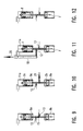
- FIG. 7 is designed structurally simpler than the first embodiment. Only one of the pistons, in this embodiment the piston 2a located at the inlet opening, is hydraulically driven. Consequently, only one control port 10 is provided. In contrast to the embodiment of FIG. 1, the control opening 10 also does not open at the side of the piston 2 facing the other piston 2b, but at its opposite side, so that the piston 2a is moved towards the piston 2b by a pressure in the drive chamber 11a , The spring element 9a, acting against the pressure in the drive chamber 11a, is arranged on the other side of the piston 2a with respect to the drive chamber 11a.
- FIGS. 7 to 12 The function of the second embodiment is described below with reference to FIGS. 7 to 12, wherein the positions of FIGS. 7 to 12 correspond to the positions in FIGS. 1 to 6 with respect to the position of the metering volume 16. Due to the different arrangement of drive chambers and spring elements, however, the movement of the dosing volume 1 b with respect to the pressure build-up and down in the control opening 10 is phase-shifted.
- the lubricant line 18 is in the starting position of FIG. 7, in which the piston 2b is in its moved to the other piston 2a towards the end position and the piston 2a is in its moving away from the piston 2b end position, pressure-free.
- the pistons 2a, 2b are pressed by the respectively acting on them spring elements 9a, 9b to form the metering volume 16 against corresponding stops and the metering volume 16 is filled with lubricant. If now the lubricant line 18 is acted upon by a lubrication pump, not shown, at the beginning of a lubrication cycle, it acts on the drive chamber 11a of the piston 2a (FIG. 8).
- the piston 2a moves against the action of the spring element 9a with its end face 14a via the inlet opening 12 and closes it.
- the piston 2b is displaced by the piston 2b against the action of the spring element 9b, so that the dosing volume 16 with the pistons 2a, 2b moves towards the discharge opening 13.
- the lubricant line 18 is no longer pressurized and the piston 2a, 2b move under the action of the spring elements 9a, 9b in the direction of the initial position associated, located at the inlet port 12 end positions, while the lubricant from the drive chamber 11a through the lubricant line 18 flows back ( Figures 11 and 12).
- the spring elements 9a, 9b may be interchanged respectively with the drive chambers 11a, 11b, without this fundamentally changing the mode of operation, only the phase reference to the pressure in the lubricant line changes.
- the piston 2b lying on the delivery opening 13 can be driven against a stop, so that the piston 2a situated at the inlet opening 12 is moved against the stationary piston 2b and thus conveys the lubricant out of the metering volume.
Landscapes
- Engineering & Computer Science (AREA)
- General Engineering & Computer Science (AREA)
- Mechanical Engineering (AREA)
- Reciprocating Pumps (AREA)
- Details Of Reciprocating Pumps (AREA)
Applications Claiming Priority (1)
| Application Number | Priority Date | Filing Date | Title |
|---|---|---|---|
| DE102006038389.3A DE102006038389B4 (de) | 2006-08-15 | 2006-08-15 | Schmiermittel-Dosierpumpe und Dosierverfahren mit zwei gegeneinander beweglichen Kolben |
Publications (1)
| Publication Number | Publication Date |
|---|---|
| EP1900993A2 true EP1900993A2 (fr) | 2008-03-19 |
Family
ID=37682655
Family Applications (1)
| Application Number | Title | Priority Date | Filing Date |
|---|---|---|---|
| EP07012465A Withdrawn EP1900993A2 (fr) | 2006-08-15 | 2007-06-26 | Pompe de dosage à additif de lubrifiant et procédé de dosage doté de deux pistons se déplaçant l'un contre l'autre |
Country Status (4)
| Country | Link |
|---|---|
| US (1) | US8506268B2 (fr) |
| EP (1) | EP1900993A2 (fr) |
| JP (1) | JP5260001B2 (fr) |
| DE (1) | DE102006038389B4 (fr) |
Families Citing this family (3)
| Publication number | Priority date | Publication date | Assignee | Title |
|---|---|---|---|---|
| CN104006282A (zh) * | 2014-05-27 | 2014-08-27 | 郑州奥特科技有限公司 | 一种双路控制吸脂器及废脂回收装置 |
| CN107023741B (zh) * | 2016-02-02 | 2019-02-26 | 沈阳路邦机械有限公司 | 注油机 |
| CN120521134A (zh) * | 2025-07-23 | 2025-08-22 | 成都中寰流体控制设备股份有限公司 | 一种防爆电动注入泵 |
Family Cites Families (18)
| Publication number | Priority date | Publication date | Assignee | Title |
|---|---|---|---|---|
| BE404479A (fr) | ||||
| DE390212C (de) | 1922-06-02 | 1924-02-21 | Oskar Reissig | Ventillose Schmierpumpe mit umlaufendem Steuerschieber und einer oder mehreren um ihn herum achsial angeordneten Bohrungen fuer die Kolben |
| US1689419A (en) * | 1926-02-03 | 1928-10-30 | American Mach & Foundry | Valveless pump or compressor |
| DE507853C (de) | 1928-03-27 | 1930-09-20 | Helios App Wetzel & Schlosshau | Schmierpumpe |
| GB322246A (en) | 1928-09-05 | 1929-12-05 | Karl Godeke | Improvements in lubricating pumps |
| FR782769A (fr) * | 1934-12-17 | 1935-06-12 | Pompe aspirante et foulante sans clapet ni distributeur | |
| US2891718A (en) * | 1956-11-06 | 1959-06-23 | Thompson Ramo Wooldridge Inc | Opposed free piston reciprocating gas compressor |
| DE1138952B (de) | 1960-02-29 | 1962-10-31 | Strojosvit Np | Dosiereinrichtung fuer Schmiermittel, Fluessigkeiten u. dgl. |
| US3302578A (en) * | 1965-04-28 | 1967-02-07 | H V Hardman Co Inc | Metering pump |
| US3461805A (en) * | 1968-02-26 | 1969-08-19 | Photo Instr Tooling Co | Reciprocating piston metering pump |
| US3695788A (en) * | 1970-01-09 | 1972-10-03 | Bernard A Loomans | Apparatus for pumping fluids |
| JPS521502A (en) * | 1975-06-23 | 1977-01-07 | Noritsu Co Ltd | Plunger pump |
| US4534168A (en) * | 1983-06-30 | 1985-08-13 | Brantly Newby O | Pump jack |
| DE3631343A1 (de) | 1986-09-15 | 1988-03-17 | Albert Zimmer | Verfahren zum dosieren von fluessigen bis hochviskosen medien mit ueberwachung der mediumsabgabe sowie dosierventil zur ausuebung des verfahrens |
| DE3900697A1 (de) | 1989-01-12 | 1990-07-19 | Draegerwerk Ag | Ventillose pumpe |
| EP0854314B1 (fr) | 1993-03-18 | 2003-08-20 | B a r m a g AG | Methode pour alimenter en lubrifiant un palier antifriction |
| JP3129099B2 (ja) * | 1994-09-09 | 2001-01-29 | ブラザー工業株式会社 | 駆動装置付ポンプ |
| US6976831B2 (en) * | 2003-06-25 | 2005-12-20 | Halliburton Energy Services, Inc. | Transmissionless variable output pumping unit |
-
2006
- 2006-08-15 DE DE102006038389.3A patent/DE102006038389B4/de active Active
-
2007
- 2007-06-26 EP EP07012465A patent/EP1900993A2/fr not_active Withdrawn
- 2007-08-14 JP JP2007211243A patent/JP5260001B2/ja active Active
- 2007-08-14 US US11/838,760 patent/US8506268B2/en not_active Expired - Fee Related
Also Published As
| Publication number | Publication date |
|---|---|
| JP2008111545A (ja) | 2008-05-15 |
| US20080044303A1 (en) | 2008-02-21 |
| DE102006038389A1 (de) | 2008-02-21 |
| US8506268B2 (en) | 2013-08-13 |
| DE102006038389B4 (de) | 2022-11-17 |
| JP5260001B2 (ja) | 2013-08-14 |
Similar Documents
| Publication | Publication Date | Title |
|---|---|---|
| EP0825348B1 (fr) | Amplificateur de pression de fluide, particulièrement de fluide hydraulique | |
| DE2536858C3 (fr) | ||
| EP2236213B1 (fr) | Dispositif de sortie | |
| DE2612609A1 (de) | Pumpensystem | |
| EP1303700A1 (fr) | Pompe a liquides epais | |
| DE102011082420A1 (de) | Flüssigkeitsspender | |
| DE3048776A1 (de) | Druckwandlergeraet | |
| DE2617375C2 (de) | Vorrichtung zum Steuern von Schmiereinrichtungen | |
| EP1900993A2 (fr) | Pompe de dosage à additif de lubrifiant et procédé de dosage doté de deux pistons se déplaçant l'un contre l'autre | |
| DE19953183C2 (de) | Mikrodosierer | |
| DE2711208C2 (de) | Vorrichtung zum Dosieren und Abfüllen insbesondere hochviskoser Medien | |
| EP3033523B1 (fr) | Pompe à matière épaisse à deux cylindres comportant une vanne d'aiguillage | |
| DE1503334A1 (de) | Hydraulische Vorrichtung zum Erzeugen einer hin- und hergehenden Bewegung | |
| EP4401889B1 (fr) | Dispositif de décharge portionnée d'un milieu liquide | |
| EP4497511A1 (fr) | Dispositif de distribution de fluide | |
| DE2358569C2 (de) | Vorrichtung zum Dosieren eines flüssigen Zusatzstoffes in eine Hauptflüssigkeitsmenge | |
| EP1538336B1 (fr) | Pompe de dosage | |
| DE60302056T2 (de) | Abgabepumpe für medien | |
| DE3828274A1 (de) | Hydraulikpumpe | |
| DE2824680A1 (de) | Vorrichtung zum dosieren und abfuellen insbesondere hochviskoser medien | |
| EP0801982B1 (fr) | Burette à piston | |
| DE102004022226A1 (de) | Dosierverteiler mit verbesserter Dosiergenauigkeit durch Leckageleitung und Verfahren zum Verteilen und Dosieren eines Verteilermediums | |
| DE4420694A1 (de) | Dosierpumpe | |
| DE2300045A1 (de) | Dosiervorrichtung fuer fluessigkeiten | |
| DE2641250A1 (de) | Druckfluid-impulsfrequenzumwandler |
Legal Events
| Date | Code | Title | Description |
|---|---|---|---|
| PUAI | Public reference made under article 153(3) epc to a published international application that has entered the european phase |
Free format text: ORIGINAL CODE: 0009012 |
|
| AK | Designated contracting states |
Kind code of ref document: A2 Designated state(s): AT BE BG CH CY CZ DE DK EE ES FI FR GB GR HU IE IS IT LI LT LU LV MC MT NL PL PT RO SE SI SK TR |
|
| AX | Request for extension of the european patent |
Extension state: AL BA HR MK YU |
|
| STAA | Information on the status of an ep patent application or granted ep patent |
Free format text: STATUS: THE APPLICATION IS DEEMED TO BE WITHDRAWN |
|
| 18D | Application deemed to be withdrawn |
Effective date: 20100104 |