EP3033523B1 - Pompe à matière épaisse à deux cylindres comportant une vanne d'aiguillage - Google Patents
Pompe à matière épaisse à deux cylindres comportant une vanne d'aiguillage Download PDFInfo
- Publication number
- EP3033523B1 EP3033523B1 EP14719011.0A EP14719011A EP3033523B1 EP 3033523 B1 EP3033523 B1 EP 3033523B1 EP 14719011 A EP14719011 A EP 14719011A EP 3033523 B1 EP3033523 B1 EP 3033523B1
- Authority
- EP
- European Patent Office
- Prior art keywords
- delivery
- thick matter
- matter pump
- ring element
- slot
- Prior art date
- Legal status (The legal status is an assumption and is not a legal conclusion. Google has not performed a legal analysis and makes no representation as to the accuracy of the status listed.)
- Active
Links
Images


Classifications
-
- F—MECHANICAL ENGINEERING; LIGHTING; HEATING; WEAPONS; BLASTING
- F04—POSITIVE - DISPLACEMENT MACHINES FOR LIQUIDS; PUMPS FOR LIQUIDS OR ELASTIC FLUIDS
- F04B—POSITIVE-DISPLACEMENT MACHINES FOR LIQUIDS; PUMPS
- F04B15/00—Pumps adapted to handle specific fluids, e.g. by selection of specific materials for pumps or pump parts
-
- F—MECHANICAL ENGINEERING; LIGHTING; HEATING; WEAPONS; BLASTING
- F04—POSITIVE - DISPLACEMENT MACHINES FOR LIQUIDS; PUMPS FOR LIQUIDS OR ELASTIC FLUIDS
- F04B—POSITIVE-DISPLACEMENT MACHINES FOR LIQUIDS; PUMPS
- F04B7/00—Piston machines or pumps characterised by having positively-driven valving
- F04B7/0019—Piston machines or pumps characterised by having positively-driven valving a common distribution member forming a single discharge distributor for a plurality of pumping chambers
-
- F—MECHANICAL ENGINEERING; LIGHTING; HEATING; WEAPONS; BLASTING
- F04—POSITIVE - DISPLACEMENT MACHINES FOR LIQUIDS; PUMPS FOR LIQUIDS OR ELASTIC FLUIDS
- F04B—POSITIVE-DISPLACEMENT MACHINES FOR LIQUIDS; PUMPS
- F04B15/00—Pumps adapted to handle specific fluids, e.g. by selection of specific materials for pumps or pump parts
- F04B15/02—Pumps adapted to handle specific fluids, e.g. by selection of specific materials for pumps or pump parts the fluids being viscous or non-homogeneous
- F04B15/023—Pumps adapted to handle specific fluids, e.g. by selection of specific materials for pumps or pump parts the fluids being viscous or non-homogeneous supply of fluid to the pump by gravity through a hopper, e.g. without intake valve
-
- F—MECHANICAL ENGINEERING; LIGHTING; HEATING; WEAPONS; BLASTING
- F04—POSITIVE - DISPLACEMENT MACHINES FOR LIQUIDS; PUMPS FOR LIQUIDS OR ELASTIC FLUIDS
- F04B—POSITIVE-DISPLACEMENT MACHINES FOR LIQUIDS; PUMPS
- F04B19/00—Machines or pumps having pertinent characteristics not provided for in, or of interest apart from, groups F04B1/00 - F04B17/00
- F04B19/20—Other positive-displacement pumps
- F04B19/22—Other positive-displacement pumps of reciprocating-piston type
-
- F—MECHANICAL ENGINEERING; LIGHTING; HEATING; WEAPONS; BLASTING
- F04—POSITIVE - DISPLACEMENT MACHINES FOR LIQUIDS; PUMPS FOR LIQUIDS OR ELASTIC FLUIDS
- F04B—POSITIVE-DISPLACEMENT MACHINES FOR LIQUIDS; PUMPS
- F04B7/00—Piston machines or pumps characterised by having positively-driven valving
- F04B7/0019—Piston machines or pumps characterised by having positively-driven valving a common distribution member forming a single discharge distributor for a plurality of pumping chambers
- F04B7/0023—Piston machines or pumps characterised by having positively-driven valving a common distribution member forming a single discharge distributor for a plurality of pumping chambers and having a rotating movement
-
- F—MECHANICAL ENGINEERING; LIGHTING; HEATING; WEAPONS; BLASTING
- F04—POSITIVE - DISPLACEMENT MACHINES FOR LIQUIDS; PUMPS FOR LIQUIDS OR ELASTIC FLUIDS
- F04B—POSITIVE-DISPLACEMENT MACHINES FOR LIQUIDS; PUMPS
- F04B7/00—Piston machines or pumps characterised by having positively-driven valving
- F04B7/0019—Piston machines or pumps characterised by having positively-driven valving a common distribution member forming a single discharge distributor for a plurality of pumping chambers
- F04B7/0026—Piston machines or pumps characterised by having positively-driven valving a common distribution member forming a single discharge distributor for a plurality of pumping chambers and having an oscillating movement
Definitions
- the invention relates to a sludge pump with a material feed container and two with frontal orifices connected to one passage in the container wall conveyor cylinders, which are connected by a arranged inside the material feed hopper alternately with the container interior and a delivery line and the delivery piston alternately a Mountainhub and perform a delivery stroke.
- the pipe switch has an inlet opening pointing in the direction of the outlet openings and designed as a circular arc-shaped elongated hole, the width of which corresponds to the diameter and its length to the outer spacing of the mouth openings and which each has a closure projection protruding beyond the outer edge of the inlet opening in the pivoting direction Longitudinal extent corresponds to the distance between the orifices ( DE-195 03 986 A1 ).
- the well-known thick matter pump is characterized in particular by the fact that the inlet opening formed as a curved elongated hole and the two closure extensions of the pipe switch ensure that at least temporarily a short circuit of the two delivery cylinders is established during the pivoting or switching process of the pipe switch.
- the present invention seeks to improve the well-known slurry pump of the type specified in that both in the stationary and in the moving state of the pipe switch an adequate seal in the area of the diverter tank wall separation point is guaranteed.
- the solution according to the invention consists essentially in that the pipe switch has a bow-shaped elongated hole metallic ring element and arranged between the ring member and an output side connected to the conveyor line pivot pipe, a slot comprehensive breakthrough exhibiting pad member, wherein the ring member axially limited relative to the pivot tube is movable and can be pressed against the inner surface of the container wall via the cushion element under the action of the delivery pressure in the transfer tube.
- the cushioning element has a non-circular areal cross-sectional shape.
- the preferably rubber-elastic material behaves almost incompressible, much like a liquid that transfers the hydraulic pressure evenly in all directions. This means that the pressure of the conveyed material from the inside of the diverter valve ideally propagates uniformly over the upholstery element, namely into the closure extensions.
- the metallic ring member is pressed against the inner surface of the container wall, although only the inlet contour of the cushion member is in contact with the pressurized conveying medium.
- a further improvement in this regard can be achieved by providing within the cushioning element a kind of fluid or gel pocket over which the pressure can be transferred even better.
- the container wall carries on its inner surface facing the ring member a provided with the mouth openings replaceable wear plate. This can be relatively easily replaced in case of wear. In addition, this can be used against the material container wear-resistant and therefore more expensive material.
- a further advantageous embodiment of the invention provides that the ring element has a schwenkrohr facility arranged, adapted over its outer contour to the cushion element, step-shaped pocket for receiving the cushion element.
- a further improvement in this regard is achieved when the ring member is also limited to the slot through a stepped pocket wall whose height is smaller than the outer edge of the bag.
- a further improvement of the positioning of the ring element on the pivot tube is achieved in that at the cylinder-side end of the pivot tube an arcuately limited, penetrated by a pivot tube channel elevation is arranged, which has a corresponding outer contour of the pocket in the ring element.
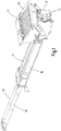
- thick matter pump has a material supply container 10 for receiving thick matter, such as liquid concrete.
- the liquid concrete is conveyed via a pipe bend 12 in an only indicated conveying line 14. This is done by means of two delivery cylinders 16,17, with the front side Mouth openings 18,19 are connected to one passage opening 18 ', 19' in the container wall 20 and their delivery piston 22,23 alternately perform a filling stroke and a delivery stroke.
- Inside the material feed container 10 there is a diverter 24, via which the delivery cylinders 16, 17 are alternately connectable to the container interior 21 and the delivery line 14.
- the diverter 24 is pivotable via a hydraulic drive mechanism in each case in its desired position with respect to the mouth openings 18,19.
- the delivery pistons 22,23 are moved by means of hydraulic cylinder-piston units 26,27, of which in Fig. 1 only the cylinders are indicated schematically.
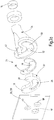
- the diverter 24 has an opening in the direction of the orifices 18,19, designed as arcuate curved slot 28 inlet opening whose width corresponds to the diameter and the length of the outer distance of the mouth openings 18,19 and each one in Pivoting direction over the outer edge of the inlet opening 28 protruding closure approach 30,31, the longitudinal extent corresponds to the distance between the mouth openings 18,19 approximately.
- a special feature of the invention is that the pipe switch has a bow-shaped elongated hole 28 exhibiting metallic ring member 32 and a between the ring member 32 and an output side connected to the feed line pivot pipe 34 arranged cushion member 36.
- the padding element 36 has a long hole 28 in the ring member 32 comprehensive slot-shaped opening 38.
- the ring member 32 is axially movable relative to the pivot tube 34 and is under the action of the delivery pressure generated in the delivery stroke in the transfer tube 34 via the ring member 32 against the inner surface of the container wall 20 pressed.
- the container wall 20 carries on its the inner surface facing the ring member 32 a with the passage openings 18 ', 19' and provided with a bearing bore 40 for the bearing pin 42 replaceable metallic wear plate 20 '.
- the ring member 32 has a pivot tube side arranged, adapted over its outer contour to the cushion member 36 step-shaped pocket 44 for receiving the cushion member 36.
- the ring member 32 is also limited to the slot 28 through a stepped inner pocket wall 46 whose height is smaller than the outer pocket edge 48.
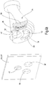
- At the cylinder-side end of the pivot tube 34 is an arcuately limited elevation 50, which is penetrated by the pivot tube channel 52 ( Fig. 3a ) and one of the pockets 44 in the ring element 32 corresponding outer contour ( Fig. 3b ).
- the cushion element 36 consists of a resilient, elastic or rubber-elastic material. A further improvement in the contact pressure effect can be achieved in that the cushioning element 36 contains a filling designed as an incompressible liquid.
- the inlet opening of the pipe switch or of the ring element is designed with its curved slot shape so that the two delivery cylinders 16,17 are short-circuited via their orifices 18,19 within the slot 28. If, in this position, both delivery cylinders 16, 17 carry out a delivery stroke with their delivery pistons 22, 23, a smooth, bumpless switching process can be ensured. In preparation for the switching operation, a pre-pressure can already be built up in the previously filled delivery cylinder while the closure attachment 30, 31 is being moved past the diverter 24. This gives a further improvement in terms of the continuous flow through the delivery line during the switching process. On the other hand, this means that the piston speeds and thus also the stroke duration during the filling stroke and the delivery stroke are different, since due to the described functional Special features for the filling stroke less time available than for the delivery stroke.
- the invention relates to a sludge pump with a material feed container 10 and two with end-side orifices 18,19 to a respective passage opening 18 ', 19' in the container wall 20 connected to the delivery cylinders 16,17.
- the delivery cylinders 16, 17 can be connected in alternation with the container interior 21 and a delivery line 14 by a pipe switch 24 arranged in the interior of the material delivery container 10, while their delivery pistons 22, 23 alternately perform a filling stroke and a delivery stroke.
- the diverter 24 has an opening in the direction of openings 18,19 facing, as a circular arc curved slot 28 formed inlet opening whose width corresponds to the diameter and its length to the outer distance of the mouth openings 18,19 and each one in the pivoting direction on the outer edge of the slot projecting closure approach 30,31, whose longitudinal extent corresponds to the distance between the mouth openings.
- the pipe switch 24 a the arcuate slot 28 exhibiting metallic ring member 32 and a connected between the ring member 32 and an output side to the feed line 14 Swivel tube 34 arranged, a the slot 28 comprehensive breakthrough 38 exhibiting cushion member 36, wherein the ring member 32 relative to the pivot tube 34 axially movable and under the action of the delivery pressure in the transfer tube 24 via the cushion member 36 against the inner surface of the container wall can be pressed.
Landscapes
- Engineering & Computer Science (AREA)
- Mechanical Engineering (AREA)
- General Engineering & Computer Science (AREA)
- Reciprocating Pumps (AREA)
- Details Of Reciprocating Pumps (AREA)
Claims (8)
- Pompe à matière épaisse avec un récipient de dépôt de matière (10) et deux cylindres de refoulement (16, 17) raccordés respectivement à une ouverture de passage (18', 19') dans la paroi de récipient par des ouvertures de décharge (18, 19), qui peuvent être reliés en alternance à l'intérieur (21) du récipient et à une conduite de refoulement (14) au moyen d'une vanne d'aiguillage (24) disposée à l'intérieur du récipient de dépôt de matière (10), et dont les pistons de refoulement (22, 23) effectuent en alternance une course de remplissage et une course de refoulement, dans laquelle la vanne d'aiguillage (24) présente une ouverture d'admission orientée en direction des ouvertures de décharge (18, 19) et réalisée en forme de trou oblong (28) incurvé en forme d'arc, dont la largeur correspond au diamètre et dont la longueur correspond à la distance extérieure des ouvertures de passage (18', 19') et qui présente une aile de fermeture (30, 31) saillante respectivement au-delà du bord extérieur du trou oblong (28) dans la direction de pivotement, caractérisée en ce que la vanne d'aiguillage (24) présente un élément annulaire métallique (32) présentant le trou oblong en forme d'arc (28) ainsi qu'un élément de rembourrage (36) disposé entre l'élément annulaire (32) et un tube pivotant (34) relié par sa sortie à la conduite de refoulement (14) et présentant un passage (38) comprenant le trou oblong (28), dans laquelle l'élément annulaire (32) est mobile axialement par rapport au tube pivotant (34) et peut être pressé contre la face intérieure de la paroi de récipient (20) par l'intermédiaire de l'élément de rembourrage (36) sous l'action de la pression de refoulement dans la vanne d'aiguillage (24).
- Pompe à matière épaisse selon la revendication 1, caractérisée en ce que la paroi de récipient (20) porte sur sa face intérieure tournée vers l'élément annulaire (32) une plaque d'usure échangeable (20') dotée des ouvertures de passage (18', 19').
- Pompe à matière épaisse selon la revendication 1 ou 2, caractérisée en ce que l'élément annulaire (32) présente une poche (44) disposée vers le tube pivotant, adaptée par son contour extérieur à l'élément de rembourrage (36), façonnée en forme étagée en formant un bord de poche extérieur (48), afin de contenir l'élément de rembourrage (36).
- Pompe à matière épaisse selon la revendication 3, caractérisée en ce que l'élément annulaire (32) est également limité en direction du trou oblong (28) par une paroi de poche étagée (46), dont la hauteur est inférieure au bord de poche extérieur (48).
- Pompe à matière épaisse selon la revendication 3 ou 4, caractérisée en ce qu'une élévation limitée en forme d'arc (50) traversée par un canal du tube pivotant (52) est disposée sur l'extrémité du tube pivotant (34) proche des cylindres, et présente un contour extérieur correspondant à la poche (44) dans l'élément annulaire (32).
- Pompe à matière épaisse selon l'une quelconque des revendications 1 à 5, caractérisée en ce que l'élément de rembourrage (36) se compose d'un matériau souple ou élastique.
- Pompe à matière épaisse selon l'une quelconque des revendications 1 à 6, caractérisée en ce que l'élément de rembourrage (36) se compose au moins en partie d'un matériau élastique de type caoutchouc.
- Pompe à matière épaisse selon l'une quelconque des revendications 1 à 7, caractérisée en ce que l'élément de rembourrage (36) contient un remplissage sous forme de liquide incompressible.
Applications Claiming Priority (2)
| Application Number | Priority Date | Filing Date | Title |
|---|---|---|---|
| DE102013215990.0A DE102013215990A1 (de) | 2013-08-13 | 2013-08-13 | Zweizylinder-Dickstoffpumpe mit Rohrweiche |
| PCT/EP2014/058291 WO2015022088A1 (fr) | 2013-08-13 | 2014-04-24 | Pompe à matière épaisse à deux cylindres comportant une vanne d'aiguillage |
Publications (2)
| Publication Number | Publication Date |
|---|---|
| EP3033523A1 EP3033523A1 (fr) | 2016-06-22 |
| EP3033523B1 true EP3033523B1 (fr) | 2017-08-23 |
Family
ID=50543602
Family Applications (1)
| Application Number | Title | Priority Date | Filing Date |
|---|---|---|---|
| EP14719011.0A Active EP3033523B1 (fr) | 2013-08-13 | 2014-04-24 | Pompe à matière épaisse à deux cylindres comportant une vanne d'aiguillage |
Country Status (7)
| Country | Link |
|---|---|
| US (1) | US20160160851A1 (fr) |
| EP (1) | EP3033523B1 (fr) |
| JP (1) | JP2016528433A (fr) |
| KR (1) | KR20160041910A (fr) |
| CN (1) | CN105683569A (fr) |
| DE (1) | DE102013215990A1 (fr) |
| WO (1) | WO2015022088A1 (fr) |
Families Citing this family (3)
| Publication number | Priority date | Publication date | Assignee | Title |
|---|---|---|---|---|
| EP3282125A1 (fr) * | 2016-08-11 | 2018-02-14 | Putzmeister Engineering GmbH | Vanne pour matériaux visqueux |
| CN110195466B (zh) * | 2019-04-24 | 2021-07-13 | 湖南睿弓机械科技有限公司 | 清淤机械及其液压系统 |
| JP7620288B2 (ja) * | 2021-03-12 | 2025-01-23 | 古河機械金属株式会社 | 水流揚鉱システム |
Family Cites Families (20)
| Publication number | Priority date | Publication date | Assignee | Title |
|---|---|---|---|---|
| US3663129A (en) * | 1970-09-18 | 1972-05-16 | Leon A Antosh | Concrete pump |
| US3989420A (en) * | 1974-05-15 | 1976-11-02 | J. I. Case Company | Concrete pumping apparatus |
| DE2415276C2 (de) * | 1974-03-29 | 1976-11-11 | Friedrich Schwing | Pumpe zum Fördern von Dickstoffen, insbesondere Beton |
| US3963385A (en) * | 1975-05-05 | 1976-06-15 | Caban Angel M | Valve assembly for concrete pumps |
| DE2829181A1 (de) * | 1978-07-03 | 1980-01-17 | Scheele Maschf W | Rohrweiche fuer eine betonpumpe |
| DE3153268C2 (en) * | 1981-01-31 | 1988-01-28 | Friedrich Wilh. Schwing Gmbh, 4690 Herne, De | Two-cylinder viscous-material pump, preferably concrete pump |
| JPS6063079U (ja) * | 1983-10-07 | 1985-05-02 | 合資会社 八代石油 | コンクリ−トポンプの吐出口と分配管の間隙をシ−ルするリング |
| JPS60175780A (ja) * | 1984-02-23 | 1985-09-09 | Kyokuto Kaihatsu Kogyo Co Ltd | コンクリ−トポンプにおける吸送部の切換装置 |
| DE3419832A1 (de) * | 1984-05-26 | 1985-11-28 | Karl Dipl.-Ing. 7000 Stuttgart Schlecht | Rohrweiche einer dickstoff, insbesondere beton foerdernden doppelkolbenpumpe |
| DE3430193A1 (de) * | 1984-08-16 | 1986-02-27 | Linnhoff & Thesenfitz Maschinen- und Anlagenbau GmbH, 8754 Großostheim | Schwenkrohrsystem fuer betonpumpen |
| US5037275A (en) * | 1987-06-27 | 1991-08-06 | Karl Schlecht | Pipe junction switch for two-cylinder thick-material pump |
| DE3824466A1 (de) * | 1988-07-19 | 1990-01-25 | Putzmeister Maschf | Mehrzylinder-dickstoffpumpe |
| US5302094A (en) * | 1988-07-19 | 1994-04-12 | Putzmeister-Werk Maschinenfabrik Gmbh | Tube switch for a double-cylinder sludge pump |
| US5180294A (en) * | 1992-03-04 | 1993-01-19 | Confloat Consulting Ltd. | Concrete pump having pressurized seal for swing tube |
| DE19503986A1 (de) | 1995-02-07 | 1996-08-08 | Hudelmaier Ulrike | Verfahren und Vorrichtung zum Fördern von Beton oder anderen Dickstoffen |
| US6857861B2 (en) * | 2002-05-15 | 2005-02-22 | Kennametal Inc. | Ring for concrete pump |
| KR20040057014A (ko) * | 2002-12-24 | 2004-07-01 | 한락수 | 콘크리트 펌프용 접동 구조물 및 그 제작방법 |
| DE10343802B4 (de) * | 2003-09-22 | 2007-12-06 | Schwing Gmbh | Kolben-Dickstoffpumpe mit kontinuierlichem Förderstrom |
| WO2007111689A2 (fr) * | 2005-11-08 | 2007-10-04 | Good Earth Tools, Inc. | Bagues d'etancheite pour pompes a boue abrasive |
| CN101718265B (zh) * | 2009-12-16 | 2012-10-10 | 三一重工股份有限公司 | 泵送设备的密封组件、分配阀总成、泵送设备及控制方法 |
-
2013
- 2013-08-13 DE DE102013215990.0A patent/DE102013215990A1/de not_active Withdrawn
-
2014
- 2014-04-24 JP JP2016533842A patent/JP2016528433A/ja active Pending
- 2014-04-24 KR KR1020167002999A patent/KR20160041910A/ko not_active Ceased
- 2014-04-24 WO PCT/EP2014/058291 patent/WO2015022088A1/fr not_active Ceased
- 2014-04-24 EP EP14719011.0A patent/EP3033523B1/fr active Active
- 2014-04-24 CN CN201480045266.6A patent/CN105683569A/zh active Pending
-
2016
- 2016-02-12 US US15/042,202 patent/US20160160851A1/en not_active Abandoned
Non-Patent Citations (1)
| Title |
|---|
| None * |
Also Published As
| Publication number | Publication date |
|---|---|
| US20160160851A1 (en) | 2016-06-09 |
| CN105683569A (zh) | 2016-06-15 |
| EP3033523A1 (fr) | 2016-06-22 |
| KR20160041910A (ko) | 2016-04-18 |
| JP2016528433A (ja) | 2016-09-15 |
| DE102013215990A1 (de) | 2015-02-19 |
| WO2015022088A1 (fr) | 2015-02-19 |
Similar Documents
| Publication | Publication Date | Title |
|---|---|---|
| DE102009005318B3 (de) | Verfahren zur Förderung breiiger Massen und Pumpvorrichtung zur Förderung breiiger Massen | |
| DE1498394A1 (de) | Abgabevorrichtung | |
| EP1982104B1 (fr) | Dispositif hydraulique avec pompe de lubrification | |
| LU84030A1 (de) | Verfahren und vorrichtung zum abgeben von viskosen konzentraten veraenderlicher viskositaet in genau dosierbaren mengen von variablem volumen | |
| DE202009002951U1 (de) | Schmierstoffverteiler | |
| EP3033523B1 (fr) | Pompe à matière épaisse à deux cylindres comportant une vanne d'aiguillage | |
| DE2447054A1 (de) | Dreiwege-verteiler fuer betondoppelpumpen | |
| EP2025978A2 (fr) | Distributeur pour un dispositif de nettoyage des vitres dans un véhicule | |
| EP0315750B1 (fr) | Pompe pour matière épaisse | |
| EP3939705A1 (fr) | Appareil de nettoyage haute pression | |
| EP0016410B1 (fr) | Pompe pour matières visqueuses, notamment pompe à béton | |
| DE4136097C1 (fr) | ||
| EP0036945A2 (fr) | Dispositif pour transporter des matériaux fluides | |
| DE3034467A1 (de) | Hydraulische vorrichtung zum ueberwachen einer verbindung | |
| CH652805A5 (de) | Druckumsetzer mit mindestens drei oelhydraulisch angetriebenen kolben. | |
| DE2943967C2 (fr) | ||
| DE947040C (de) | Hydraulisch angetriebene Kolbenpumpe zur Foerderung von dickfluessigen, breiigen Massen, z. B. Beton | |
| EP1900993A2 (fr) | Pompe de dosage à additif de lubrifiant et procédé de dosage doté de deux pistons se déplaçant l'un contre l'autre | |
| EP1590586B1 (fr) | Soupape pour le transvasement en cadence de produits d'un recipient d'alimentation dans des recipients d'emballage | |
| DE102017126651B4 (de) | Pumpeinrichtung mit über einem gemeinsamen Antrieb gekoppelten Pumpen | |
| DE19927070B4 (de) | Hydraulische Presse | |
| DE2404345A1 (de) | Beduesungsvorrichtung, insbesondere fuer untertaegige gewinnungsbetriebe | |
| DE2024877C3 (de) | Handpumpe in Verbindung mit einer motorgetriebenen Kreiselpumpe | |
| EP0485862B1 (fr) | Pompe pour matière épaisse ayant un couple de cylindres aspirant et refoulant alternativement | |
| EP3695119B1 (fr) | Pompe à pistons comportant un élément de commande forcée |
Legal Events
| Date | Code | Title | Description |
|---|---|---|---|
| PUAI | Public reference made under article 153(3) epc to a published international application that has entered the european phase |
Free format text: ORIGINAL CODE: 0009012 |
|
| 17P | Request for examination filed |
Effective date: 20160308 |
|
| AK | Designated contracting states |
Kind code of ref document: A1 Designated state(s): AL AT BE BG CH CY CZ DE DK EE ES FI FR GB GR HR HU IE IS IT LI LT LU LV MC MK MT NL NO PL PT RO RS SE SI SK SM TR |
|
| AX | Request for extension of the european patent |
Extension state: BA ME |
|
| DAX | Request for extension of the european patent (deleted) | ||
| GRAP | Despatch of communication of intention to grant a patent |
Free format text: ORIGINAL CODE: EPIDOSNIGR1 |
|
| INTG | Intention to grant announced |
Effective date: 20170509 |
|
| GRAS | Grant fee paid |
Free format text: ORIGINAL CODE: EPIDOSNIGR3 |
|
| GRAA | (expected) grant |
Free format text: ORIGINAL CODE: 0009210 |
|
| AK | Designated contracting states |
Kind code of ref document: B1 Designated state(s): AL AT BE BG CH CY CZ DE DK EE ES FI FR GB GR HR HU IE IS IT LI LT LU LV MC MK MT NL NO PL PT RO RS SE SI SK SM TR |
|
| REG | Reference to a national code |
Ref country code: GB Ref legal event code: FG4D Free format text: NOT ENGLISH |
|
| REG | Reference to a national code |
Ref country code: CH Ref legal event code: EP |
|
| REG | Reference to a national code |
Ref country code: AT Ref legal event code: REF Ref document number: 921640 Country of ref document: AT Kind code of ref document: T Effective date: 20170915 |
|
| REG | Reference to a national code |
Ref country code: IE Ref legal event code: FG4D Free format text: LANGUAGE OF EP DOCUMENT: GERMAN |
|
| REG | Reference to a national code |
Ref country code: DE Ref legal event code: R096 Ref document number: 502014005162 Country of ref document: DE |
|
| REG | Reference to a national code |
Ref country code: NL Ref legal event code: MP Effective date: 20170823 |
|
| REG | Reference to a national code |
Ref country code: LT Ref legal event code: MG4D |
|
| PG25 | Lapsed in a contracting state [announced via postgrant information from national office to epo] |
Ref country code: NL Free format text: LAPSE BECAUSE OF FAILURE TO SUBMIT A TRANSLATION OF THE DESCRIPTION OR TO PAY THE FEE WITHIN THE PRESCRIBED TIME-LIMIT Effective date: 20170823 Ref country code: HR Free format text: LAPSE BECAUSE OF FAILURE TO SUBMIT A TRANSLATION OF THE DESCRIPTION OR TO PAY THE FEE WITHIN THE PRESCRIBED TIME-LIMIT Effective date: 20170823 Ref country code: LT Free format text: LAPSE BECAUSE OF FAILURE TO SUBMIT A TRANSLATION OF THE DESCRIPTION OR TO PAY THE FEE WITHIN THE PRESCRIBED TIME-LIMIT Effective date: 20170823 Ref country code: FI Free format text: LAPSE BECAUSE OF FAILURE TO SUBMIT A TRANSLATION OF THE DESCRIPTION OR TO PAY THE FEE WITHIN THE PRESCRIBED TIME-LIMIT Effective date: 20170823 Ref country code: NO Free format text: LAPSE BECAUSE OF FAILURE TO SUBMIT A TRANSLATION OF THE DESCRIPTION OR TO PAY THE FEE WITHIN THE PRESCRIBED TIME-LIMIT Effective date: 20171123 Ref country code: SE Free format text: LAPSE BECAUSE OF FAILURE TO SUBMIT A TRANSLATION OF THE DESCRIPTION OR TO PAY THE FEE WITHIN THE PRESCRIBED TIME-LIMIT Effective date: 20170823 |
|
| PG25 | Lapsed in a contracting state [announced via postgrant information from national office to epo] |
Ref country code: RS Free format text: LAPSE BECAUSE OF FAILURE TO SUBMIT A TRANSLATION OF THE DESCRIPTION OR TO PAY THE FEE WITHIN THE PRESCRIBED TIME-LIMIT Effective date: 20170823 Ref country code: PL Free format text: LAPSE BECAUSE OF FAILURE TO SUBMIT A TRANSLATION OF THE DESCRIPTION OR TO PAY THE FEE WITHIN THE PRESCRIBED TIME-LIMIT Effective date: 20170823 Ref country code: LV Free format text: LAPSE BECAUSE OF FAILURE TO SUBMIT A TRANSLATION OF THE DESCRIPTION OR TO PAY THE FEE WITHIN THE PRESCRIBED TIME-LIMIT Effective date: 20170823 Ref country code: BG Free format text: LAPSE BECAUSE OF FAILURE TO SUBMIT A TRANSLATION OF THE DESCRIPTION OR TO PAY THE FEE WITHIN THE PRESCRIBED TIME-LIMIT Effective date: 20171123 Ref country code: ES Free format text: LAPSE BECAUSE OF FAILURE TO SUBMIT A TRANSLATION OF THE DESCRIPTION OR TO PAY THE FEE WITHIN THE PRESCRIBED TIME-LIMIT Effective date: 20170823 Ref country code: IS Free format text: LAPSE BECAUSE OF FAILURE TO SUBMIT A TRANSLATION OF THE DESCRIPTION OR TO PAY THE FEE WITHIN THE PRESCRIBED TIME-LIMIT Effective date: 20171223 Ref country code: GR Free format text: LAPSE BECAUSE OF FAILURE TO SUBMIT A TRANSLATION OF THE DESCRIPTION OR TO PAY THE FEE WITHIN THE PRESCRIBED TIME-LIMIT Effective date: 20171124 |
|
| PG25 | Lapsed in a contracting state [announced via postgrant information from national office to epo] |
Ref country code: CZ Free format text: LAPSE BECAUSE OF FAILURE TO SUBMIT A TRANSLATION OF THE DESCRIPTION OR TO PAY THE FEE WITHIN THE PRESCRIBED TIME-LIMIT Effective date: 20170823 Ref country code: RO Free format text: LAPSE BECAUSE OF FAILURE TO SUBMIT A TRANSLATION OF THE DESCRIPTION OR TO PAY THE FEE WITHIN THE PRESCRIBED TIME-LIMIT Effective date: 20170823 Ref country code: DK Free format text: LAPSE BECAUSE OF FAILURE TO SUBMIT A TRANSLATION OF THE DESCRIPTION OR TO PAY THE FEE WITHIN THE PRESCRIBED TIME-LIMIT Effective date: 20170823 |
|
| REG | Reference to a national code |
Ref country code: DE Ref legal event code: R097 Ref document number: 502014005162 Country of ref document: DE |
|
| PG25 | Lapsed in a contracting state [announced via postgrant information from national office to epo] |
Ref country code: SM Free format text: LAPSE BECAUSE OF FAILURE TO SUBMIT A TRANSLATION OF THE DESCRIPTION OR TO PAY THE FEE WITHIN THE PRESCRIBED TIME-LIMIT Effective date: 20170823 Ref country code: EE Free format text: LAPSE BECAUSE OF FAILURE TO SUBMIT A TRANSLATION OF THE DESCRIPTION OR TO PAY THE FEE WITHIN THE PRESCRIBED TIME-LIMIT Effective date: 20170823 Ref country code: SK Free format text: LAPSE BECAUSE OF FAILURE TO SUBMIT A TRANSLATION OF THE DESCRIPTION OR TO PAY THE FEE WITHIN THE PRESCRIBED TIME-LIMIT Effective date: 20170823 |
|
| PLBE | No opposition filed within time limit |
Free format text: ORIGINAL CODE: 0009261 |
|
| STAA | Information on the status of an ep patent application or granted ep patent |
Free format text: STATUS: NO OPPOSITION FILED WITHIN TIME LIMIT |
|
| 26N | No opposition filed |
Effective date: 20180524 |
|
| PG25 | Lapsed in a contracting state [announced via postgrant information from national office to epo] |
Ref country code: SI Free format text: LAPSE BECAUSE OF FAILURE TO SUBMIT A TRANSLATION OF THE DESCRIPTION OR TO PAY THE FEE WITHIN THE PRESCRIBED TIME-LIMIT Effective date: 20170823 |
|
| PG25 | Lapsed in a contracting state [announced via postgrant information from national office to epo] |
Ref country code: MT Free format text: LAPSE BECAUSE OF FAILURE TO SUBMIT A TRANSLATION OF THE DESCRIPTION OR TO PAY THE FEE WITHIN THE PRESCRIBED TIME-LIMIT Effective date: 20170823 |
|
| PG25 | Lapsed in a contracting state [announced via postgrant information from national office to epo] |
Ref country code: MC Free format text: LAPSE BECAUSE OF FAILURE TO SUBMIT A TRANSLATION OF THE DESCRIPTION OR TO PAY THE FEE WITHIN THE PRESCRIBED TIME-LIMIT Effective date: 20170823 |
|
| REG | Reference to a national code |
Ref country code: CH Ref legal event code: PL |
|
| REG | Reference to a national code |
Ref country code: BE Ref legal event code: MM Effective date: 20180430 |
|
| GBPC | Gb: european patent ceased through non-payment of renewal fee |
Effective date: 20180424 |
|
| REG | Reference to a national code |
Ref country code: IE Ref legal event code: MM4A |
|
| PG25 | Lapsed in a contracting state [announced via postgrant information from national office to epo] |
Ref country code: LU Free format text: LAPSE BECAUSE OF NON-PAYMENT OF DUE FEES Effective date: 20180424 |
|
| PG25 | Lapsed in a contracting state [announced via postgrant information from national office to epo] |
Ref country code: BE Free format text: LAPSE BECAUSE OF NON-PAYMENT OF DUE FEES Effective date: 20180430 Ref country code: GB Free format text: LAPSE BECAUSE OF NON-PAYMENT OF DUE FEES Effective date: 20180424 Ref country code: LI Free format text: LAPSE BECAUSE OF NON-PAYMENT OF DUE FEES Effective date: 20180430 Ref country code: CH Free format text: LAPSE BECAUSE OF NON-PAYMENT OF DUE FEES Effective date: 20180430 |
|
| PG25 | Lapsed in a contracting state [announced via postgrant information from national office to epo] |
Ref country code: FR Free format text: LAPSE BECAUSE OF NON-PAYMENT OF DUE FEES Effective date: 20180430 Ref country code: IE Free format text: LAPSE BECAUSE OF NON-PAYMENT OF DUE FEES Effective date: 20180424 |
|
| PG25 | Lapsed in a contracting state [announced via postgrant information from national office to epo] |
Ref country code: PT Free format text: LAPSE BECAUSE OF FAILURE TO SUBMIT A TRANSLATION OF THE DESCRIPTION OR TO PAY THE FEE WITHIN THE PRESCRIBED TIME-LIMIT Effective date: 20170823 |
|
| PG25 | Lapsed in a contracting state [announced via postgrant information from national office to epo] |
Ref country code: CY Free format text: LAPSE BECAUSE OF FAILURE TO SUBMIT A TRANSLATION OF THE DESCRIPTION OR TO PAY THE FEE WITHIN THE PRESCRIBED TIME-LIMIT Effective date: 20170823 Ref country code: HU Free format text: LAPSE BECAUSE OF FAILURE TO SUBMIT A TRANSLATION OF THE DESCRIPTION OR TO PAY THE FEE WITHIN THE PRESCRIBED TIME-LIMIT; INVALID AB INITIO Effective date: 20140424 Ref country code: MK Free format text: LAPSE BECAUSE OF NON-PAYMENT OF DUE FEES Effective date: 20170823 |
|
| PG25 | Lapsed in a contracting state [announced via postgrant information from national office to epo] |
Ref country code: AL Free format text: LAPSE BECAUSE OF FAILURE TO SUBMIT A TRANSLATION OF THE DESCRIPTION OR TO PAY THE FEE WITHIN THE PRESCRIBED TIME-LIMIT Effective date: 20170823 |
|
| PGFP | Annual fee paid to national office [announced via postgrant information from national office to epo] |
Ref country code: DE Payment date: 20200424 Year of fee payment: 7 Ref country code: TR Payment date: 20200424 Year of fee payment: 7 |
|
| REG | Reference to a national code |
Ref country code: AT Ref legal event code: MM01 Ref document number: 921640 Country of ref document: AT Kind code of ref document: T Effective date: 20190424 |
|
| PGFP | Annual fee paid to national office [announced via postgrant information from national office to epo] |
Ref country code: IT Payment date: 20200423 Year of fee payment: 7 |
|
| PG25 | Lapsed in a contracting state [announced via postgrant information from national office to epo] |
Ref country code: AT Free format text: LAPSE BECAUSE OF NON-PAYMENT OF DUE FEES Effective date: 20190424 |
|
| REG | Reference to a national code |
Ref country code: DE Ref legal event code: R119 Ref document number: 502014005162 Country of ref document: DE |
|
| PG25 | Lapsed in a contracting state [announced via postgrant information from national office to epo] |
Ref country code: DE Free format text: LAPSE BECAUSE OF NON-PAYMENT OF DUE FEES Effective date: 20211103 |
|
| PG25 | Lapsed in a contracting state [announced via postgrant information from national office to epo] |
Ref country code: IT Free format text: LAPSE BECAUSE OF NON-PAYMENT OF DUE FEES Effective date: 20200424 |
|
| PG25 | Lapsed in a contracting state [announced via postgrant information from national office to epo] |
Ref country code: IT Free format text: LAPSE BECAUSE OF NON-PAYMENT OF DUE FEES Effective date: 20210424 |