EP1900995A1 - Lampe de mineur et méthode de fabrication d'une lampe de mineur - Google Patents
Lampe de mineur et méthode de fabrication d'une lampe de mineur Download PDFInfo
- Publication number
- EP1900995A1 EP1900995A1 EP06027069A EP06027069A EP1900995A1 EP 1900995 A1 EP1900995 A1 EP 1900995A1 EP 06027069 A EP06027069 A EP 06027069A EP 06027069 A EP06027069 A EP 06027069A EP 1900995 A1 EP1900995 A1 EP 1900995A1
- Authority
- EP
- European Patent Office
- Prior art keywords
- housing
- lamp
- ring
- led
- power led
- Prior art date
- Legal status (The legal status is an assumption and is not a legal conclusion. Google has not performed a legal analysis and makes no representation as to the accuracy of the status listed.)
- Withdrawn
Links
- 238000004519 manufacturing process Methods 0.000 title claims abstract description 10
- 238000000034 method Methods 0.000 title claims abstract 3
- 238000004023 plastic welding Methods 0.000 claims description 11
- 230000002093 peripheral effect Effects 0.000 claims description 7
- 229920003023 plastic Polymers 0.000 claims description 6
- 239000004033 plastic Substances 0.000 claims description 6
- 230000017525 heat dissipation Effects 0.000 claims description 3
- 238000009432 framing Methods 0.000 claims description 2
- 150000001875 compounds Chemical class 0.000 claims 1
- 238000011161 development Methods 0.000 description 7
- 230000018109 developmental process Effects 0.000 description 7
- 239000007789 gas Substances 0.000 description 7
- 238000005538 encapsulation Methods 0.000 description 4
- WHXSMMKQMYFTQS-UHFFFAOYSA-N Lithium Chemical compound [Li] WHXSMMKQMYFTQS-UHFFFAOYSA-N 0.000 description 3
- 238000009825 accumulation Methods 0.000 description 3
- 229910052744 lithium Inorganic materials 0.000 description 3
- 239000002360 explosive Substances 0.000 description 2
- 239000004519 grease Substances 0.000 description 2
- 238000005286 illumination Methods 0.000 description 2
- 230000010354 integration Effects 0.000 description 2
- 230000003321 amplification Effects 0.000 description 1
- 238000001816 cooling Methods 0.000 description 1
- 238000010586 diagram Methods 0.000 description 1
- 230000000694 effects Effects 0.000 description 1
- 239000012528 membrane Substances 0.000 description 1
- 238000003199 nucleic acid amplification method Methods 0.000 description 1
- 230000003287 optical effect Effects 0.000 description 1
- 238000007789 sealing Methods 0.000 description 1
Images

Classifications
-
- F—MECHANICAL ENGINEERING; LIGHTING; HEATING; WEAPONS; BLASTING
- F21—LIGHTING
- F21L—LIGHTING DEVICES OR SYSTEMS THEREOF, BEING PORTABLE OR SPECIALLY ADAPTED FOR TRANSPORTATION
- F21L4/00—Electric lighting devices with self-contained electric batteries or cells
- F21L4/08—Electric lighting devices with self-contained electric batteries or cells characterised by means for in situ recharging of the batteries or cells
-
- F—MECHANICAL ENGINEERING; LIGHTING; HEATING; WEAPONS; BLASTING
- F21—LIGHTING
- F21V—FUNCTIONAL FEATURES OR DETAILS OF LIGHTING DEVICES OR SYSTEMS THEREOF; STRUCTURAL COMBINATIONS OF LIGHTING DEVICES WITH OTHER ARTICLES, NOT OTHERWISE PROVIDED FOR
- F21V29/00—Protecting lighting devices from thermal damage; Cooling or heating arrangements specially adapted for lighting devices or systems
- F21V29/50—Cooling arrangements
- F21V29/70—Cooling arrangements characterised by passive heat-dissipating elements, e.g. heat-sinks
-
- F—MECHANICAL ENGINEERING; LIGHTING; HEATING; WEAPONS; BLASTING
- F21—LIGHTING
- F21V—FUNCTIONAL FEATURES OR DETAILS OF LIGHTING DEVICES OR SYSTEMS THEREOF; STRUCTURAL COMBINATIONS OF LIGHTING DEVICES WITH OTHER ARTICLES, NOT OTHERWISE PROVIDED FOR
- F21V15/00—Protecting lighting devices from damage
- F21V15/01—Housings, e.g. material or assembling of housing parts
-
- F—MECHANICAL ENGINEERING; LIGHTING; HEATING; WEAPONS; BLASTING
- F21—LIGHTING
- F21V—FUNCTIONAL FEATURES OR DETAILS OF LIGHTING DEVICES OR SYSTEMS THEREOF; STRUCTURAL COMBINATIONS OF LIGHTING DEVICES WITH OTHER ARTICLES, NOT OTHERWISE PROVIDED FOR
- F21V21/00—Supporting, suspending, or attaching arrangements for lighting devices; Hand grips
- F21V21/08—Devices for easy attachment to any desired place, e.g. clip, clamp, magnet
- F21V21/088—Clips; Clamps
- F21V21/0885—Clips; Clamps for portable lighting devices
-
- F—MECHANICAL ENGINEERING; LIGHTING; HEATING; WEAPONS; BLASTING
- F21—LIGHTING
- F21V—FUNCTIONAL FEATURES OR DETAILS OF LIGHTING DEVICES OR SYSTEMS THEREOF; STRUCTURAL COMBINATIONS OF LIGHTING DEVICES WITH OTHER ARTICLES, NOT OTHERWISE PROVIDED FOR
- F21V23/00—Arrangement of electric circuit elements in or on lighting devices
- F21V23/04—Arrangement of electric circuit elements in or on lighting devices the elements being switches
- F21V23/0414—Arrangement of electric circuit elements in or on lighting devices the elements being switches specially adapted to be used with portable lighting devices
-
- F—MECHANICAL ENGINEERING; LIGHTING; HEATING; WEAPONS; BLASTING
- F21—LIGHTING
- F21V—FUNCTIONAL FEATURES OR DETAILS OF LIGHTING DEVICES OR SYSTEMS THEREOF; STRUCTURAL COMBINATIONS OF LIGHTING DEVICES WITH OTHER ARTICLES, NOT OTHERWISE PROVIDED FOR
- F21V29/00—Protecting lighting devices from thermal damage; Cooling or heating arrangements specially adapted for lighting devices or systems
- F21V29/50—Cooling arrangements
- F21V29/70—Cooling arrangements characterised by passive heat-dissipating elements, e.g. heat-sinks
- F21V29/74—Cooling arrangements characterised by passive heat-dissipating elements, e.g. heat-sinks with fins or blades
-
- F—MECHANICAL ENGINEERING; LIGHTING; HEATING; WEAPONS; BLASTING
- F21—LIGHTING
- F21V—FUNCTIONAL FEATURES OR DETAILS OF LIGHTING DEVICES OR SYSTEMS THEREOF; STRUCTURAL COMBINATIONS OF LIGHTING DEVICES WITH OTHER ARTICLES, NOT OTHERWISE PROVIDED FOR
- F21V33/00—Structural combinations of lighting devices with other articles, not otherwise provided for
- F21V33/0064—Health, life-saving or fire-fighting equipment
-
- F—MECHANICAL ENGINEERING; LIGHTING; HEATING; WEAPONS; BLASTING
- F21—LIGHTING
- F21V—FUNCTIONAL FEATURES OR DETAILS OF LIGHTING DEVICES OR SYSTEMS THEREOF; STRUCTURAL COMBINATIONS OF LIGHTING DEVICES WITH OTHER ARTICLES, NOT OTHERWISE PROVIDED FOR
- F21V33/00—Structural combinations of lighting devices with other articles, not otherwise provided for
- F21V33/0064—Health, life-saving or fire-fighting equipment
- F21V33/0076—Safety or security signalisation, e.g. smoke or burglar alarms, earthquake detectors; Self-defence devices
-
- F—MECHANICAL ENGINEERING; LIGHTING; HEATING; WEAPONS; BLASTING
- F21—LIGHTING
- F21Y—INDEXING SCHEME ASSOCIATED WITH SUBCLASSES F21K, F21L, F21S and F21V, RELATING TO THE FORM OR THE KIND OF THE LIGHT SOURCES OR OF THE COLOUR OF THE LIGHT EMITTED
- F21Y2115/00—Light-generating elements of semiconductor light sources
- F21Y2115/10—Light-emitting diodes [LED]
Definitions
- the invention relates to a light insert, in particular for mine lamps according to the preamble of patent claim 1 and a lamp with a light insert according to claim 6.
- the invention further relates to a method for producing a miner's lamp according to claim 13.
- the invention aims to remedy this situation.
- the invention is based on the object to provide a light insert and a lamp with a light insert, which has a high light output and in which a heat accumulation is prevented and which is also inexpensive to manufacture. According to the invention, this object is solved by the features of the characterizing part of patent claim 1.
- a light insert is created, which has a high light output and in which a heat accumulation is prevented and which is also inexpensive to manufacture.
- the means for dissipating heat is a heat conducting sheet, which is heat-conductively connected to the reflector housing.
- precisely one high-power LED is arranged on the printed circuit board such that it is positioned on the axis of rotation of the reflector housing.
- the arrangement on the optical axis of the reflector housing a maximum reflection of the emitted light is achieved.
- the low-power LEDs are arranged at regular intervals around the high-power LED. As a result, a uniform light amplification is achieved.
- the low-power LEDs and the high-power LED both separately and jointly activated.
- different degrees of illumination can be achieved.
- the heat baffle with a cover plate limits a space which is filled with a thermal grease. This increases the efficiency of heat dissipation.
- a lamp having the features of patent claim 6.
- a lamp is provided which has a high light output and in which a heat accumulation is prevented and which is also inexpensive to manufacture.
- the housing is designed in several parts, wherein at least the disc and the disc housing receiving part are made of the same plastic. This allows a homogeneous connection of the disc with the housing.
- the disc is connected to the housing by means of plastic welding.
- a recess is provided on the housing, behind which a switching element is arranged, and a control panel for operating a switching element is provided, which has a peripheral edge which engages in a gap between a ring, the circumferential of the recess Framing operating part is arranged on the housing, and the housing is formed, wherein the ring is connected to the housing by means of plastic welding, that the peripheral edge of the control unit is pressed into the gap.
- a charging connection socket is arranged on the lamp, which can be covered by a slide, which is movably arranged in a rail. In this way, a possibility for external charging of a battery disposed within the lamp housing is made possible, which is protected by the slider against external influences.
- a gas sensor is arranged on the lamp, which is integrated in the lamp housing. This allows early alarming of the worker in the presence of harmful or explosive gases.
- the invention is further based on the object to provide a method for producing a miner's lamp, which allows a high-density connection of the housing parts and thereby ensures a high-density encapsulation of the light and thus meets the requirements of the highest protection classes. According to the invention, this object is solved by the features of claim 12.
- a method for producing a miner's lamp which enables a high-density connection of the housing parts and thus ensures a high-density encapsulation of the light insert and thus meets the requirements of the highest protection classes. Due to the high-density encapsulation in particular an uncontrolled heat leakage is avoided, which in turn can lead to hazards in connection with high-explosive gases.
- a recess is placed on the housing, under which a switching element is arranged, and on the recess of a ring is arranged, wherein the housing and the ring are formed such that between these a gap is formed, and an elastic operating part having a peripheral edge, is arranged between the housing and ring, that the edge engages in the gap and that the operating element acts on the switching element when externally pressurized, and subsequently the ring is connected to the housing by means of plastic welding, wherein the edge between ring and housing is pressed.
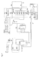
- the miner's lamp chosen as an exemplary embodiment essentially comprises a lamp insert 1, which is arranged in a housing which is formed from two housing parts 2, 3 and a disk 4.
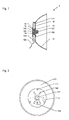
- the lamp insert 1 comprises a reflector 11 which is substantially parabolic. In the region of its smallest inner diameter three fixing tabs 111 for fixing a printed circuit board 12 are integrally formed on the reflector 11 circumferentially at equal intervals.
- a high-power LED 121 is arranged centrally. To the high-power LED 121 star-shaped six low-power LEDs 122 are arranged. Between two low-power LEDs 122, an additional indicator low-power LED 123 is arranged. The indicator low power LED 123 is used to control a charge.
- a connection cable 124 is arranged on the printed circuit board 12.
- a heat-conducting sheet 13 is arranged on the printed circuit board 12.
- the casseroleleitblech 13 is circular and covers the connection area of the high-power LED 121.
- the heat conduction plate 13 is held between the circuit board 12 and the cover plate 14, which covers the reflector body 11 at its smallest inner diameter.
- the cover plate 14 is designed substantially circular and has in its center an inwardly directed curvature 142. In the middle, a breakthrough 141 is introduced into the cover plate 14, into which the inner curvature 142 opens. Laterally, an opening 143 for the passage of the connecting cable 124 of the printed circuit board 12 is inserted into the cover plate 14.
- the cavity formed by the inner arch 142 and the opening 141 is closed by a circular diaphragm 15. This is a membrane that allows heat to pass through.
- the closed by the diaphragm 15 cavity is filled with thermal grease 16,
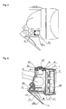
- the housing part 2 is designed substantially elliptical. On its rear side, a hollow cylinder for receiving a lithium battery 7 is integrally formed. Above the receptacle for the lithium battery 7, a charging port 21 is provided. To cover the charging port 21, the housing part 2 has a cover 22, which is pivotally mounted with a tab 222 via a rivet 223 on the housing part 2. On its side opposite the tab 222, a sealing element 221 is attached to the cover 22, by means of which the charging connection 21 can be covered. In addition to the charging connection 21, a recess 25 is made in the housing part 2 for the passage of a switch 5, which can be operated via an operating part 52.
- the control unit 52 is designed in the manner of a plastic knob, on whose side facing the switch 5 a truncated cone 521 is formed. On its outer thyak an edge 522 is integrally formed on the control panel 52 circumferentially.
- the control unit 52 is located with its peripheral edge 522 on the housing part 2, the recess 25 on the periphery and is connected to a fastening ring 53 with the housing part 2.
- a shoulder 26 is formed around the recess 25 on the housing part 2, on which the fastening ring 53 rests and forms a gap 54 into which the edge 522 of the operating part 52 engages.
- the fastening ring 53 is connected to the housing part 2 by means of plastic welding.
- a receptacle for a gas sensor 8 is arranged on the housing part 2.
- a further switch 6 for the operation of the gas sensor 8 is provided.
- the switch 6 in turn comprises a control panel 61 with a truncated cone 611 and an edge 612.
- the control panel 61 is fixed in the manner described above by means of a mounting ring 62 on the housing part 2, wherein the edge 612 of the control panel 61 in the between fastening ring 62nd and housing part 2 formed gap 63 engages.
- a fastening element 23 for fastening the miner's lamp is furthermore arranged on the housing part 2.
- a tab 231 is integrally formed on the fastening element 23, which is pivotably mounted on the housing part 2 by means of a screw 232 which is guided through an eyelet 24 integrally formed on the housing part 2.
- a recess 233 is introduced, which is designed to taper in stages in the direction of the screw 232.
- a spring element 235 is arranged, which is connected at its screw 232 facing the end with the fastening element 23 and is biased against the opposite end of the fastener 23 in the manner of a terminal.
- a spring 27 is integrally formed on the housing part 2, surrounding its housing part edges, for connection to the housing part 3.
- the housing part 3 is designed like a hood with an elliptical basic shape. In its top surface, a circular recess 31 for receiving a transparent pane 4 is introduced.
- the disc 4 is on the inside of the housing part 3, the recess 31 overlapping connected to the housing part 3 by means of plastic welding.
- a groove 33 for receiving the spring 27 of the housing part 2 is introduced in the peripheral edge 32 of the housing part 3.
- the housing parts 2 and 3 are first produced separately.
- a recess 25 is introduced into the housing part 2 for fastening the switch 5, below which a switching element 51 is arranged later.
- a fastening ring 53 is arranged, wherein in the gap 54 formed between the fastening ring 53 and the housing part 2, the edge 522 of the operating part 52 is introduced.
- the fixing ring 53 which is made of the same plastic, as the housing part 2, attached to the housing part 2 by means of plastic welding.
- the housing part 3 and to be fixed in this transparent disc 4 are made of the same plastic.
- the disc 4 is fixed in the housing part 3 such that the disc 4, the recess 31 is arranged overlapping on the inside of the housing part 3 and is subsequently connected by means of plastic welding to the housing part 3.
- the housing part 3 After inserting the lamp insert 1 and the lithium battery 7 in the housing part 2, the housing part 3 is placed on the housing part such that the spring 27 of the housing part 2 engages in the groove 33 of the housing part 3 and the reflector 11 centered on the disc 4 to the plant comes. Subsequently, the housing part 3 is screwed to the housing part 2 by means of screws (not shown).
Landscapes
- Engineering & Computer Science (AREA)
- General Engineering & Computer Science (AREA)
- Arrangement Of Elements, Cooling, Sealing, Or The Like Of Lighting Devices (AREA)
Applications Claiming Priority (2)
| Application Number | Priority Date | Filing Date | Title |
|---|---|---|---|
| CNB2006101245317A CN100473900C (zh) | 2006-09-13 | 2006-09-13 | 一种制备矿灯的生产工艺 |
| CNU2006200990943U CN200961818Y (zh) | 2006-09-21 | 2006-09-21 | 用于工矿灯的快速导热散热的大功率led光源灯杯组件 |
Publications (1)
| Publication Number | Publication Date |
|---|---|
| EP1900995A1 true EP1900995A1 (fr) | 2008-03-19 |
Family
ID=38179785
Family Applications (1)
| Application Number | Title | Priority Date | Filing Date |
|---|---|---|---|
| EP06027069A Withdrawn EP1900995A1 (fr) | 2006-09-13 | 2006-12-29 | Lampe de mineur et méthode de fabrication d'une lampe de mineur |
Country Status (1)
| Country | Link |
|---|---|
| EP (1) | EP1900995A1 (fr) |
Cited By (1)
| Publication number | Priority date | Publication date | Assignee | Title |
|---|---|---|---|---|
| DE102010013783A1 (de) * | 2010-04-03 | 2011-10-06 | Protool Gmbh | Beleuchtungsvorrichtung mit LEDs |
Citations (2)
| Publication number | Priority date | Publication date | Assignee | Title |
|---|---|---|---|---|
| EP1445532A1 (fr) * | 2003-02-10 | 2004-08-11 | Zedel | Lampe électrique portative équipée d'un système optique basculant |
| WO2006025757A1 (fr) * | 2004-08-31 | 2006-03-09 | S.C. Electromax S.R.L. | Lampe au chapeau pour mineur |
-
2006
- 2006-12-29 EP EP06027069A patent/EP1900995A1/fr not_active Withdrawn
Patent Citations (2)
| Publication number | Priority date | Publication date | Assignee | Title |
|---|---|---|---|---|
| EP1445532A1 (fr) * | 2003-02-10 | 2004-08-11 | Zedel | Lampe électrique portative équipée d'un système optique basculant |
| WO2006025757A1 (fr) * | 2004-08-31 | 2006-03-09 | S.C. Electromax S.R.L. | Lampe au chapeau pour mineur |
Cited By (2)
| Publication number | Priority date | Publication date | Assignee | Title |
|---|---|---|---|---|
| DE102010013783A1 (de) * | 2010-04-03 | 2011-10-06 | Protool Gmbh | Beleuchtungsvorrichtung mit LEDs |
| DE102010013783B4 (de) * | 2010-04-03 | 2013-11-21 | Festool Group Gmbh & Co. Kg | Beleuchtungsvorrichtung mit LEDs |
Similar Documents
| Publication | Publication Date | Title |
|---|---|---|
| EP1721102B1 (fr) | Lampe | |
| EP1405377B1 (fr) | Module a diodes electroluminescentes pour dispositifs d'eclairage | |
| DE102008052869B4 (de) | Leuchte mit LED-Tragschiene | |
| EP1776255B1 (fr) | Bloc optique de vehicule a moteur dote d'un diffuseur en plastique | |
| DE102017214668A1 (de) | Fassung mit bewegbar gelagerter Optik | |
| EP2410233A1 (fr) | Lampe de poche | |
| DE102009042615B4 (de) | Anschlusselement zur elektrischen Anbindung einer LED | |
| DE202014001946U1 (de) | Lampe | |
| EP1893910B1 (fr) | Lampe portative | |
| DE102005041333A1 (de) | Leuchtelementeinsatz für einen Beleuchtungskörper, Handlauf und Dekorelement mit einem Leuchtelementeinsatz | |
| EP1900995A1 (fr) | Lampe de mineur et méthode de fabrication d'une lampe de mineur | |
| DE202011003418U1 (de) | Leuchtenvorrichtung mit einer Halbleiterlichtquelle | |
| DE19543852A1 (de) | Kraftfahrzeugscheinwerfer mit Hochdruckgasentladungslampe | |
| EP0108368A1 (fr) | Dispositif optique avertisseur ou indicateur à diodes photoémissives | |
| DE102007056270B4 (de) | Beleuchtungseinheit mit einer LED-Lichtquelle | |
| EP0314031A2 (fr) | Armature d'éclairage avec couvercle transparent et corps de lampe relié au couvercle | |
| EP2585754B1 (fr) | Appareil d'éclairage extérieur | |
| EP1510447B3 (fr) | Phare de bicyclette | |
| EP0431462A2 (fr) | Lampe portative | |
| DE202009010900U1 (de) | LED-Leuchtmittel | |
| DE202014103064U1 (de) | Leuchtenanordnung für Leuchten beispielsweise mit LEDs | |
| DE102011102645B4 (de) | Operationsleuchte mit eingesetzter Lichteinheit, die eine nach außen abdichtende Abschlussplatte aufweist | |
| DE20013717U1 (de) | Leuchte | |
| DE202018104881U1 (de) | Leuchte | |
| DE202008002760U1 (de) | Taschenlampe |
Legal Events
| Date | Code | Title | Description |
|---|---|---|---|
| PUAI | Public reference made under article 153(3) epc to a published international application that has entered the european phase |
Free format text: ORIGINAL CODE: 0009012 |
|
| AK | Designated contracting states |
Kind code of ref document: A1 Designated state(s): AT BE BG CH CY CZ DE DK EE ES FI FR GB GR HU IE IS IT LI LT LU LV MC NL PL PT RO SE SI SK TR |
|
| AX | Request for extension of the european patent |
Extension state: AL BA HR MK YU |
|
| 17P | Request for examination filed |
Effective date: 20080209 |
|
| AKX | Designation fees paid |
Designated state(s): AT BE BG CH CY CZ DE DK EE ES FI FR GB GR HU IE IS IT LI LT LU LV MC NL PL PT RO SE SI SK TR |
|
| STAA | Information on the status of an ep patent application or granted ep patent |
Free format text: STATUS: THE APPLICATION IS DEEMED TO BE WITHDRAWN |
|
| 18D | Application deemed to be withdrawn |
Effective date: 20100701 |