EP1901002A1 - Generateur de vapeur - Google Patents
Generateur de vapeur Download PDFInfo
- Publication number
- EP1901002A1 EP1901002A1 EP06746619A EP06746619A EP1901002A1 EP 1901002 A1 EP1901002 A1 EP 1901002A1 EP 06746619 A EP06746619 A EP 06746619A EP 06746619 A EP06746619 A EP 06746619A EP 1901002 A1 EP1901002 A1 EP 1901002A1
- Authority
- EP
- European Patent Office
- Prior art keywords
- vapor
- tank
- liquid
- phase flow
- outlet
- Prior art date
- Legal status (The legal status is an assumption and is not a legal conclusion. Google has not performed a legal analysis and makes no representation as to the accuracy of the status listed.)
- Withdrawn
Links
Images


Classifications
-
- F—MECHANICAL ENGINEERING; LIGHTING; HEATING; WEAPONS; BLASTING
- F22—STEAM GENERATION
- F22B—METHODS OF STEAM GENERATION; STEAM BOILERS
- F22B37/00—Component parts or details of steam boilers
- F22B37/02—Component parts or details of steam boilers applicable to more than one kind or type of steam boiler
Definitions
- the present invention relates to a steam generator for a boiler or a nuclear reactor, generates a vapor by heating a fluid, produces and discharges a vapor-liquid two phase flow of the fluid and the vapor.
- Steam generators are used in boilers or nuclear reactors for generating a vapor from a fluid.
- a fluid is introduced into a tank, the fluid in the tank is then heated with a heater and/or a heat exchanger tube to generate vapor (gas bubbles) in the fluid, and the fluid containing the gas bubbles, i.e., a vapor-liquid two phase flow is then discharged to the outside.
- the vapor-liquid two layer flow is separated into the vapor and the fluid with a vapor-liquid separator as required, and then used.
- Patent Document 1 A boiler provided with such a steam generator is disclosed in Patent Document 1 mentioned below.
- the boiler described in Patent Document 1 is configured as follows. That is, a feed pump feeds a fluid into a steam drum; a circulating pump feeds the fed fluid in the steam drum to the steam generator; the steam generator produces a vapor-liquid two phase flow of heated water by heating the fluid; the vapor-liquid two phase flow of heated water is returned to the steam drum; the vapor-liquid two phase flow of heating is separated into a vapor and a hot liquid in the steam drum; and the steam is supplied to a load of various kinds of steam use.
- Patent Document 1 Japanese Patent Application Laid-open No. H8-285204
- the vapor-liquid two phase flow of the heated water is produced by heating a fluid in the steam generator, and then the vapor-liquid two phase flow of the heated water is returned into the steam drum via a pipe.
- the cross-sectional area of the pipe gets suddenly reduced, so that there is a problem that the vapor-liquid two phase flow is contracted and the flow is disturbed.
- the present invention aims to solve the problem described above, and an object of the present invention is to provide a steam generator that can achieve highly-precise control of a discharge flow by homogenizing a flow of the vapor-liquid two phase flow and suppressing fluctuations in the flow.
- a steam generator includes a tank having an inlet in a lower part for feeding a fluid, and an outlet in an upper part for discharging a vapor-liquid two phase flow; a heating unit that produces a vapor-liquid two phase flow by heating fluid fed into the tank; and a rectifying unit that homogenizes a vapor-liquid distribution in the vapor-liquid two phase flow in the tank.
- the rectifying unit includes a porous cylindrical member that projects from the outlet into an inside of the tank.
- the rectifying unit includes an orifice that is arranged inside the outlet.
- in the rectifying unit includes a porous rectification plate that is arranged in an upper part of the tank.
- in the rectifying unit includes a plurality of balls sandwiched between a pair of fixing plates arranged in an upper part of the tank.
- the rectifying unit includes a first rectifying unit provided in an upper part of the tank, and a second rectifying unit provided to the outlet.
- the first rectifying unit includes an orifice
- the second rectifying unit includes any one of a porous cylindrical member that projects from the outlet into an inside of the tank, a porous rectification plate, and a plurality of balls sandwiched between a pair of fixing plates.
- the first rectifying unit includes a porous cylindrical member that projects from the outlet into an inside of the tank
- the second rectifying unit includes a porous rectification member
- pores of the second rectifying unit have smaller diameters than pores of the first rectifying unit
- the rectifying unit is provided in an upper part of the tank equipped with a guide plate in a shape of a cone that guides a vapor-liquid two phase flow rectified by the rectifying unit to the outlet.
- the steam generator according to the invention of claim 1 is provided with a tank that includes an inlet for feeding a fluid formed to a lower part and an outlet for discharging a vapor-liquid two phase flow formed on an upper part; and inside the tank, provided with a heating unit that produces a vapor-liquid two phase flow by heating the fed fluid, and a rectifying unit that homogenizes a vapor-liquid distribution in the vapor-liquid two phase flow in the tank.
- the fluid when a fluid is fed into the tank from the inlet, the fluid is heated by the heating unit, and then a vapor-liquid two phase flow containing bubbles is produced, and is to be discharged from the outlet after the vapor-liquid distribution in the vapor-liquid two phase flow is homogenized by the rectifying unit, so that a flow of the vapor-liquid two phase flow does not fluctuate at the outlet, and highly-precise control of the discharge flow can be achieved.
- the rectifying unit is a porous cylindrical member provided as projected from the outlet into the inside of the tank. Accordingly, when the vapor-liquid two phase flow produced in the tank passes through pores of the cylindrical member, the sizes of contained bubbles are equalized, so that fluctuations in a flow of the vapor-liquid two phase flow at the outlet can be suppressed.
- the rectifying unit is an orifice provided in the outlet. Accordingly, when the vapor-liquid two phase flow produced in the tank passes through the orifice, the pressure of the vapor-liquid two phase flow changes; consequently, the distribution of contained bubbles is homogenized; so that fluctuations in a flow of the vapor-liquid two phase flow at the outlet can be suppressed.
- the rectifying unit is a porous rectification plate provided in an upper part of the tank. Accordingly, when the vapor-liquid two phase flow produced in the tank passes through pores of the rectification plate, the sizes of contained bubbles are equalized, so that fluctuations in a flow of the vapor-liquid two phase flow at the outlet can be suppressed.
- the rectifying unit is a plurality of balls sandwiched between a pair of fixing plates provided in the upper part of the tank. Accordingly, when the vapor-liquid two phase flow produced in the tank passes through spaces between balls, the sizes of contained bubbles are equalized, so that fluctuations in a flow of the vapor-liquid two phase flow at the outlet can be suppressed.
- the rectifying unit is constructed of a first rectifying unit provided in the upper part of the tank, and a second rectifying unit provided to the outlet. Accordingly, the vapor-liquid two phase flow produced in the tank is homogenized stepwise by two of the rectifying units, so that fluctuations in a flow of the vapor-liquid two phase flow at the outlet can be suppressed.
- the first rectifying unit is constructed of an orifice
- the second rectifying unit is constructed of a porous cylindrical member provided as projected from the outlet into the inside of the tank, or a porous rectification plate, or a plurality of balls sandwiched between a pair of fixing plates.
- the first rectifying unit is constructed of a porous cylindrical member provided as projected from the outlet into the inside of the tank;
- the second rectifying unit is constructed of a porous rectification member; and pore dimensions in the second rectifying unit are set smaller than those in the first rectifying unit. Accordingly, bubbles contained in the vapor-liquid two phase flow produced in the tank are equalized in size when passing through smaller pores of the cylindrical member, and then the sizes of the contained bubbles are again equalized when passing through larger pores of the rectification member, so that equalizing the bubbles into a smaller size in advance can ensure that fluctuations in a flow of the vapor-liquid two phase flow at the outlet are suppressed.
- the rectifying unit is provided in the upper part of the tank, and equipped with a guide plate in the shape of a cone that guides a vapor-liquid two phase flow rectified by the rectifying unit to the outlet. Accordingly, the vapor-liquid two phase flow produced in the tank is to be discharged by the guide plate guiding to the outlet after being homogenized by the rectifying unit, so that secure discharging of the vapor-liquid two phase flow in a homogenized state from the outlet can ensure that fluctuations in a flow of the vapor-liquid two phase flow are suppressed.
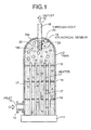
- Fig. 1 is a vertical cross-section of a steam generator according to a first embodiment of the present invention.
- a tank 12 is anchored on a mount 11.
- the tank 12 is a hollow cylinder with a spherical profile at the upper end.
- a feed pipe 14 is provided in the lower portion of the tank 12.
- the feed pipe 14 includes an inlet 13 for feeding water as a fluid.
- a discharge pipe 16 is provided at the apex of the tank 12.
- the discharge pipe 16 includes an outlet 15 for discharging a vapor-liquid two phase flow produced inside the tank 12 to the outside.
- a plurality of heaters 17 are provided inside the tank 12 in upright manner.
- the mount 11 supports bottom ends of the heaters 17 while a plurality of support plates 18 supports the rest of the body of the heaters 17.
- the heaters 17 serve as a heating unit for heating the water fed into the tank 12 thereby producing vapor-liquid two phase flow.
- a number of communicating holes are formed in each of the support plates 18 so that fluid can flow up and down.
- a rectifying unit is arranged in the tank 12.
- the rectifying unit homogenizes a vapor-liquid distribution in the vapor-liquid two phase flow produced in the tank 12.
- the homogenized vapor-liquid two phase flow is then discharged from the outlet 15.
- the rectifying unit has a configuration as follows. That is, the lower end of the discharge pipe 16 is coupled with a cylindrical member 19 that projects downward in the tank 12.
- the cylindrical member 19 includes a side surface 19a and a bottom surface 19b, and the upper end of the cylindrical member 19 communicates with the outlet 15 of the discharge pipe 16.
- a number of through-holes 20 that have the same diameter are formed on the side surface 19a and the bottom surface 19b.
- the bubbles generated inside the tank 12 vary in size and amount. Moreover, the bubbles tend to accumulate in the upper part of the tank 12, and coalesce into large bubbles, thereby forming gas pockets. Consequently, such large bubbles intermittently outflow from the outlet 15, so that fluctuations in the amount of bubbles in the vapor-liquid two phase flow generates vibrations, and the flow of the vapor-liquid two phase flow is disturbed.
- the cylindrical member 19 having the through-holes 20 is provided near the entrance of the outlet 15 from the tank 12. Even if the bubbles are built up in the upper part of the tank 12, the size and the amount of the built-up bubbles to be passed are regulated by each of the through-holes 20 of the cylindrical member 19, so that large bubbles in the tank 12 do not outflow intermittently from the outlet 15. For this reason, when the vapor-liquid two phase flow produced inside the tank 12 passes through each of the through-holes 20 of the cylindrical member 19, the bubble sizes are equalized, so that disturbance in the flow of the vapor-liquid two phase flow at the outlet 15 can be suppressed.
- the steam generator according to the first embodiment is provided with the inlet 13 for feeding water at the bottom side of the tank 12 that is hollow in shape; on the other hand, at the top end, provided with the outlet 15 for discharging the vapor-liquid two phase flow; and inside the tank 12, provided with the heaters 17 for producing the vapor-liquid two phase flow by heating water; as well as at the upper end in the tank 12, provided with the cylindrical member 19 that includes a number of the through-holes 20 as a rectifying unit that homogenizes the vapor-liquid distribution in the vapor-liquid two phase flow.
- the vapor-liquid distribution in the vapor-liquid two phase flow in the tank 12 is homogenized by the cylindrical member 19 that includes a number of the through-holes 20, and then the vapor-liquid two phase flow is discharged from the outlet 15.
- the flow of the vapor-liquid two phase flow is not disturbed when flowing out from the outlet 15, and highly-precise control of the discharge flow can be achieved.
- the lower end of the discharge pipe 16 is coupled with the cylindrical member 19 that projects downwards in the tank 12, and a number of the through-holes 20 are formed on the side surface 19a and the bottom surface 19b of the cylindrical number 19. Accordingly, the vapor-liquid two phase flow produced in the tank 12 efficiently inflows into the outlet 15 from each of the through-holes 20 of the cylindrical member 19 projected into the tank 12; and when bubbles pass through each of the through-holes 20 of the cylindrical member 19, the bubble sizes are equalized; so that disturbance in the flow of the vapor-liquid two phase flow at the outlet 15 can be securely suppressed.
- Fig. 2 is a vertical cross-section of a steam generator according to a second embodiment of the present invention.
- Members that have functions similar to those explained in the embodiment described above are assigned with the same reference numerals, and the repetition of explanations of them is omitted.
- the tank 12 is anchored on the mount 11.
- the feed pipe 14 having the inlet 13 is provided in the lower portion of the tank 12.
- the discharge pipe 16 with the outlet 15 is provided at the top end of the tank 12.
- the heaters 17 for heating water are provided inside the tank 12 in upright manner.
- the mount 11 supports bottom ends of the heaters 17 while a plurality of support plates 18 supports the rest of the body of the heaters 17.
- a rectifying unit is provided inside the outlet 15, which communicates with the tank 12.
- the rectifying unit homogenizes a vapor-liquid distribution in the vapor-liquid two phase flow produced in the tank 12.
- the homogenized vapor-liquid two phase flow is then discharged from the outlet 15.
- the rectifying unit has a configuration as follows. That is, an orifice 21 is provided at a halfway position in the discharge pipe 16, and the passage of the outlet 15 is made partially narrow.
- the bubbles generated inside the tank 12 vary in size and amount. Moreover, bubbles of various sizes tend to outflow through the outlet 15 intermittently, so that fluctuations in the amount of bubbles in the vapor-liquid two phase flow generate vibrations, and the flow of the vapor-liquid two phase flow is disturbed.
- the orifice 21 is provided inside the discharge pipe 16.
- the flow resistance at the outlet 15 increases and a flow velocity increases.
- the flow of the vapor-liquid two phase flow upstream of the orifice 21, i.e., inside the tank 12, does not diffuse downstream due to the dumping effect.
- the vapor-liquid distribution in the vapor-liquid two phase flow is homogenized, so that disturbance in the flow of the vapor-liquid two phase flow at the outlet can be suppressed.
- the steam generator according to the second embodiment is provided with the inlet 13 for feeding water at the bottom side of the tank 12 that is hollow in shape; on the other hand, at the top end, provided with the outlet 15 for discharging the vapor-liquid two phase flow; and inside the tank 12, provided with the heaters 17 for producing the vapor-liquid two phase flow by heating water; as well as in the discharge pipe 16, provided with the orifice 21 as a rectifying unit that homogenizes the vapor-liquid distribution in the vapor-liquid two phase flow.
- the vapor-liquid two phase flow in the tank 12 is to be discharged from the outlet 15 after the vapor-liquid distribution in the vapor-liquid two phase flow is homogenized when passing through the orifice 21, so that the flow of the vapor-liquid two phase flow is not disturbed at the outlet 15, and highly-precise control of the discharge flow can be achieved.
- the orifice 21 is employed as the rectifying unit, fluctuations in a flow of the vapor-liquid two phase flow can be securely suppressed by a simple configuration.
- Fig. 3 is a vertical cross-section of a steam generator according to a third embodiment of the present invention.
- Members that have functions similar to those explained in the embodiments described above are assigned with the same reference numerals, and the repetition of explanations of them is omitted.
- the tank 12 is anchored on the mount 11.
- the feed pipe 14 having the inlet 13 is provided in the lower portion of the tank 12.
- the discharge pipe 16 with the outlet 15 is provided at the top end of the tank 12.
- the heaters 17 for heating water are provided inside the tank 12 in upright manner.
- the mount 11 supports bottom ends of the heaters 17 while a plurality of support plates 18 supports the rest of the body of the heaters 17.
- a rectifying unit is provided inside the tank 12.
- the rectifying unit homogenizes the vapor-liquid distribution in the vapor-liquid two phase flow produced in the tank 12.
- the homogenized vapor-liquid two phase flow is then discharged from the outlet 15.
- the rectifying unit has a configuration as follows. That is, in an upper part of the tank 12, which is between the heaters 17 and the outlet 15, a rectification plate 31 is secured horizontally. A number of through-holes 32 that have the same diameter are formed in the rectification plate 31.
- the bubbles generated inside the tank 12 vary in size and amount; however, when the vapor-liquid two phase flow containing the bubbles passes through each of the through-holes 32 of the rectification plate 31, the bubbles are separated, and are equalized in size. Consequently, the vapor-liquid two phase flow in which the sizes of the bubbles are equalized passes through the rectification plate 31, further ascends, and then smoothly outflows from the outlet 15, so that disturbance in the flow of the vapor-liquid two phase flow at the outlet 15 can be suppressed.
- the steam generator according to the third embodiment is provided with the inlet 13 for feeding water at the bottom side of the tank 12 that is hollow in shape; on the other hand, at the top end, provided with the outlet 15 for discharging the vapor-liquid two phase flow; and inside the tank 12, provided with the heaters 17 for producing the vapor-liquid two phase flow by heating water; as well as in the upper part of the tank 12, provided with the rectification plate 31 that includes a number of the through-holes 32 as a rectifying unit that homogenizes the vapor-liquid distribution in the vapor-liquid two phase flow.
- the vapor-liquid two phase flow produced in the tank 12 is to be discharged from the outlet 15 after the sizes of bubbles are equalized and also the vapor-liquid distribution in the vapor-liquid two phase flow is homogenized when passing through each of the through-holes 32 of the rectification plate 31, so that the flow of the vapor-liquid two phase flow is not disturbed at the outlet 15, and highly-precise control of the discharge flow can be achieved.
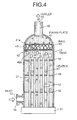
- Fig. 4 is a vertical cross-section of a steam generator according to a fourth embodiment of the present invention.
- Members that have functions similar to those explained in the embodiments described above are assigned with the same reference numerals, and the repetition of explanations of them is omitted.
- the tank 12 is anchored on the mount 11.
- the feed pipe 14 having the inlet 13 is provided in the lower portion of the tank 12.
- the discharge pipe 16 with the outlet 15 is provided at the top end of the tank 12.
- the heaters 17 for heating water are provided inside the tank 12 in upright manner.
- the mount 11 supports bottom ends of the heaters 17 while a plurality of support plates 18 supports the rest of the body of the heaters 17.
- a rectifying unit is provided inside the tank12.
- the rectifying unit homogenizes the vapor-liquid distribution in the vapor-liquid two phase flow produced in the tank 12.
- the homogenized vapor-liquid two phase flow is then discharged from the outlet 15.
- the rectifying unit has a configuration as follows. That is, in an upper part of the tank 12, which is between the heaters 17 and the outlet 15, a pair of fixing plates 41 and 42 is secured horizontally with a certain gap therebetween. Moreover, a plurality of balls 43 that has the same diameter are inserted in the gap between the pair of the fixing plates 41 and 42 in a sandwiched form, between which a plurality of communicating passages that has substantially the same diameter is formed. Through-holes 41a and 42a are formed in each of the fixing plates 41 and 42. The diameter of the through-holes 41a and 42a is smaller than the diameter of the balls 43, and larger than each of the communicating passages.
- the bubbles generated inside the tank 12 vary in size and amount; however, when the vapor-liquid two phase flow containing the bubbles passes through the communicating passages between the balls 43, the bubbles are separated, and are equalized in size. Consequently, the vapor-liquid two phase flow in which the sizes of the bubbles are equalized passes through the communicating passages, further ascends, and then smoothly outflows from the outlet 15, so that disturbance in the flow of the vapor-liquid two phase flow at the outlet 15 can be suppressed.
- the steam generator according to the fourth embodiment is provided with the inlet 13 for feeding water at the bottom side of the tank 12 that is hollow in shape; on the other hand, at the top end, provided with the outlet 15 for discharging the vapor-liquid two phase flow; and inside the tank 12, provided with the heaters 17 for producing the vapor-liquid two phase flow by heating water; as well as in the upper part of the tank 12, provided with the communicating passages formed with the balls 43 sandwiched between the pair of fixing plates 41 and 42 as a rectifying unit that homogenizes the vapor-liquid distribution in the vapor-liquid two phase flow.
- the vapor-liquid two phase flow produced in the tank 12 is to be discharged from the outlet 15 after the sizes of bubbles are equalized and also the vapor-liquid distribution in the vapor-liquid two phase flow is homogenized when passing through the communicating passages formed with the balls 43, so that the flow of the vapor-liquid two phase flow is not disturbed at the outlet 15, and highly-precise control of the discharge flow can be achieved.
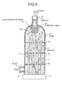
- Fig. 5 is a vertical cross-section of a steam generator according to a fifth embodiment of the present invention.
- Members that have functions similar to those explained in the embodiments described above are assigned with the same reference numerals, and the repetition of explanations of them is omitted.
- the tank 12 is anchored on the mount 11.
- the feed pipe 14 having the inlet 13 is provided in the lower portion of the tank 12.
- the discharge pipe 16 with the outlet 15 is provided at the top end of the tank 12.
- the heaters 17 for heating water are provided inside the tank 12 in upright manner.
- the mount 11 supports bottom ends of the heaters 17 while a plurality of support plates 18 supports the rest of the body of the heaters 17.
- two rectifying units are prepared for homogenizing the vapor-liquid distribution in the vapor-liquid two phase flow produced in the tank 12.
- the orifice 21 is provided at a halfway position in the discharge pipe 16, and the passage of the outlet 15 is made partially narrow.
- the cylindrical member 19 on which a number of the through-holes 20 are formed is provided at the lower end of the discharge pipe 16 that projects downward in the tank 12.
- the bubbles generated inside the tank 12 vary in size and amount. Moreover, the bubbles tend to accumulate in the upper part of the tank 12. However, when the bubbles pass through the through-holes 20 of the cylindrical member 19, the sizes and the amount of the bubbles are regulated, and the bubble sizes are equalized. Furthermore, when the vapor-liquid two phase flow in which the bubble sizes are equalized ascends and inflows into the outlet 15, a flow resistance of the vapor-liquid two phase flow containing the bubbles at the outlet 15 increases when passing through the orifice 21, and then a flow velocity increases, so that the vapor-liquid distribution in the vapor-liquid two phase flow is homogenized due to the dumping effect. As a result, disturbance in the flow of the vapor-liquid two phase flow at the outlet 15 can be securely suppressed.
- the steam generator according to the fifth embodiment is provided with the inlet 13 for feeding water at the bottom side of the tank 12 that is hollow in shape; on the other hand, at the top end, provided with the outlet 15 for discharging the vapor-liquid two phase flow; and inside the tank 12, provided with the heaters 17 for producing the vapor-liquid two phase flow by heating water; as well as, provided with the cylindrical member 19 that includes the through-holes 20 and the orifice 21 as two rectifying units that homogenize the vapor-liquid distribution in the vapor-liquid two phase flow.
- the bubble sizes are equalized; and when the vapor-liquid two phase flow passes through the orifice 21, the vapor-liquid distribution is homogenized; as a result, disturbance in the flow of the vapor-liquid two phase flow at the outlet 15 are suppressed, so that highly-precise control of the discharge flow can be achieved.
- the second rectifying unit is not limited to this.
- the rectification plate 31 that includes a number of the through-holes 32 explained in the third embodiment described above, or the balls 43 sandwiched between the pair of fixing plates 41 and 42 explained in the fourth embodiment can be used as the second rectifying unit.
- Fig. 6 is a vertical cross-section of a steam generator according to a sixth embodiment of the present invention. Members that have functions similar to those explained in the embodiments described above are assigned with the same reference numerals, and the repetition of explanations of them is omitted.
- the tank 12 is anchored on the mount 11.
- the feed pipe 14 having the inlet 13 is provided in the lower portion of the tank 12.
- the discharge pipe 16 with the outlet 15 is provided at the top end of the tank 12.
- the heaters 17 for heating water are provided inside the tank 12 in upright manner.
- the mount 11 supports bottom ends of the heaters 17 while a plurality of support plates 18 supports the rest of the body of the heaters 17.
- two rectifying units are prepared for homogenizing the vapor-liquid distribution in the vapor-liquid two phase flow produced in the tank 12.
- the cylindrical member 19 on which a number of the through-holes 20 are formed is provided at the lower end of the discharge pipe 16 that projects downward in the tank 12.
- the rectification plate 31 on which a number of the through-holes 32 are formed is secured in an upper part of the tank 12. The pore dimensions of each of the through-holes 32 on the rectification plate 31 are set smaller than those of each of the through-holes 20 on the cylindrical member 19.
- the bubbles generated inside the tank 12 vary in size and amount; however, when the vapor-liquid two phase flow containing the bubbles passes through each of the through-holes 32 of the rectification plate 31, the bubbles are separated, and are equalized in size. Furthermore, the bubbles of the vapor-liquid two phase flow may build up in the upper part of the tank 12; however, when the bubbles pass through each of the through-holes 20 of the cylindrical member 19, the sizes and the amount of the bubbles are regulated, and the bubble sizes are again equalized. As a result, disturbance in the flow of the vapor-liquid two phase flow at the outlet can be securely suppressed.
- the steam generator according to the sixth embodiment is provided with the inlet 13 for feeding water at the bottom side of the tank 12 that is hollow in shape; on the other hand, at the top end, provided with the outlet 15 for discharging the vapor-liquid two phase flow; and inside the tank 12, provided with the heaters 17 for producing the vapor-liquid two phase flow by heating water; as well as, provided with the cylindrical member 19 that includes the through-holes 20 and the rectification plate 31 that includes the through-holes 32 as two rectifying units for homogenizing the vapor-liquid distribution in the vapor-liquid two phase flow, and is configured such that the pore dimensions of each of the through-holes 32 on the rectification plate 31 is to be smaller than those of the through-holes 20 on the cylindrical member 19.
- the bubble sizes are equalized; and when the vapor-liquid two phase flow passes through each of the through-holes 20 of the cylindrical member 19, the bubble sizes are also equalized; furthermore, the pore dimensions of each of the through-holes 32 positioned upstream are set smaller than those of each of the through-holes 20 positioned downstream; as a result, while preventing pressure loss in the cylindrical member 19 of which passage dimensions are narrow, fluctuations in a flow of the vapor-liquid two phase flow at the outlet 15 are securely suppressed, so that highly-precise control of the discharge flow can be achieved.
- Fig. 7 is a vertical cross-section of a steam generator according to a seventh embodiment of the present invention.
- Members that have functions similar to those explained in the embodiments described above are assigned with the same reference numerals, and the repetition of explanations of them is omitted.
- the tank 12 is anchored on the mount 11.
- the feed pipe 14 having the inlet 13 is provided in the lower portion of the tank 12.
- the discharge pipe 16 with the outlet 15 is provided at the top end of the tank 12.
- the heaters 17 for heating water are provided inside the tank 12 in upright manner.
- the mount 11 supports bottom ends of the heaters 17 while a plurality of support plates 18 supports the rest of the body of the heaters 17.
- two sets of rectifying units for homogenizing the vapor-liquid distribution in the vapor-liquid two phase flow produced in the tank 12 are provided.
- the cylindrical member 19 on which a number of the through-holes 20 are formed is provided at the lower end of the discharge pipe 16 that projects downward in the tank 12.
- a plurality of communicating passages formed with the balls 43 sandwiched between the pair of the fixing plates 41 and 42 is provided in an upper part of the tank 12.
- the bubbles generated inside the tank 12 vary in size and amount; however, when the vapor-liquid two phase flow containing the bubbles passes through each of the communicating passages formed with the balls 43, the bubbles are separated, and are equalized in size. Furthermore, the bubbles of the vapor-liquid two phase flow may build up in the upper part of the tank 12; however, when the bubbles pass through each of the through-holes 20 of the cylindrical member 19, the sizes and the amount of the bubbles are regulated, and the bubble sizes are again equalized. As a result, disturbance in the flow of the vapor-liquid two phase flow at the outlet can be securely suppressed.
- the steam generator according to the seventh embodiment is provided with the inlet 13 for feeding water at the bottom side of the tank 12 that is hollow in shape; on the other hand, at the top end, provided with the outlet 15 for discharging the vapor-liquid two phase flow; and inside the tank 12, provided with the heaters 17 for producing the vapor-liquid two phase flow by heating water; as well as, provided with the cylindrical member 19 that includes the through-holes 20 and the balls 43 sandwiched between the fixing plates 41 and 42 to form the communicating passages as two rectifying units that homogenize the vapor-liquid distribution in the vapor-liquid two phase flow.
- the bubble sizes are equalized; and additionally the sizes of bubbles are equalized when passing through each of the through-holes 20 of the cylindrical member 19; as a result, disturbance in a flow of the vapor-liquid two phase flow at the outlet 15 are securely suppressed, so that highly-precise control of the discharge flow can be achieved. It is also possible to prevent pressure loss in the cylindrical member 19 of which passage dimensions are narrow by setting the pore dimensions of each of the communicating passages positioned upstream smaller than those of each of the through-holes 20 positioned downstream.
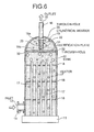
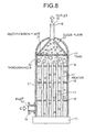
- Fig. 8 is a vertical cross-section of a steam generator according to an eighth embodiment of the present invention.
- Members that have functions similar to those explained in the embodiments described above are assigned with the same reference numerals, and the repetition of explanations of them is omitted.
- the tank 12 is anchored on the mount 11.
- the feed pipe 14 is provided in the lower portion of the tank 12.
- the feed pipe 12 includes the inlet 13 is attached.
- the discharge pipe 16 is provided at the apex of the tank 12.
- the discharge pipe 16 includes the outlet 15.
- the heaters 17 for heating water are provided inside the tank 12 in upright manner. Specifically, the mount 11 supports bottom ends of the heaters 17 while a plurality of support plates 18 supports the rest of the body of the heaters 17.
- the rectification plate 31 As a rectifying unit that homogenizes the vapor-liquid distribution in the vapor-liquid two phase flow produced in the tank 12, the rectification plate 31 is secured in an upper part of the tank 12. A number of the through-holes 32 are formed in the rectification plate 31. Moreover, a guide plate 51 in the shape of a cone is secured between the rectification plate 31 and the outlet 15. The guide plate 51 is for guiding the vapor-liquid two phase flow rectified by the rectification plate 31 to the outlet 15 without building up in the upper end area of the tank 12.
- the bubbles generated inside the tank 12 vary in size and amount. However, when the vapor-liquid two phase flow containing the bubbles passes through each of the through-holes 32 of the rectification plate 31, the bubbles are separated, and are equalized in size. Consequently, the vapor-liquid two phase flow in which the sizes of the bubbles are equalized ascends along the guide plate 51, and then smoothly outflows from the outlet 15, so that disturbance in the flow of the vapor-liquid two phase flow at the outlet 15 can be suppressed.
- the steam generator according to the eighth embodiment is provided with the inlet 13 for feeding water at the bottom side of the tank 12 that is hollow in shape; on the other hand, at the top end, provided with the outlet 15 for discharging the vapor-liquid two phase flow; inside the tank 12, provided with the heaters 17 for producing the vapor-liquid two phase flow by heating water; in the upper part of the tank 12, provided with the rectification plate 31 that includes a number of the through-holes 32 as a rectifying unit that homogenizes the vapor-liquid distribution in the vapor-liquid two phase flow; and above the rectification plate 31, provided with the guide plate 51 that guides the rectified vapor-liquid two phase flow to the outlet 15.
- the vapor-liquid two phase flow produced in the tank 12 passes through each of the through-holes 32 of the rectification plate 31, the sizes of bubbles are equalized; and then the equalized vapor-liquid two phase flow ascends along the guide plate 51 without convection, and is smoothly discharged from the outlet 15; so that a flow of the vapor-liquid two phase flow is not disturbed at the outlet 15, and highly-precise control of the discharge flow can be achieved.
- the rectifying unit according to the present invention is constructed of the cylindrical member 19, the orifice 21, the rectification plate 31, and/or the balls 43 in the embodiments described above, the configuration is not limited to this, but also an ultrasonic generator can be provided in the tank 12 or the outlet 15, and the number of the rectifying units is not limited to one or two, but also three or more units can be provided.
- the steam generator according to the present invention is configured to discharge a vapor-liquid two phase flow produced in the tank after homogenizing the vapor-liquid distribution in the vapor-liquid two phase flow, and can be applied to any kind of steam generator.
Landscapes
- Engineering & Computer Science (AREA)
- Physics & Mathematics (AREA)
- Thermal Sciences (AREA)
- Mechanical Engineering (AREA)
- General Engineering & Computer Science (AREA)
- Devices For Medical Bathing And Washing (AREA)
- Feeding, Discharge, Calcimining, Fusing, And Gas-Generation Devices (AREA)
- Cleaning By Liquid Or Steam (AREA)
- Vaporization, Distillation, Condensation, Sublimation, And Cold Traps (AREA)
Applications Claiming Priority (2)
| Application Number | Priority Date | Filing Date | Title |
|---|---|---|---|
| JP2005147916A JP2006322683A (ja) | 2005-05-20 | 2005-05-20 | 蒸気発生器 |
| PCT/JP2006/309951 WO2006123746A1 (fr) | 2005-05-20 | 2006-05-18 | Generateur de vapeur |
Publications (3)
| Publication Number | Publication Date |
|---|---|
| EP1901002A1 true EP1901002A1 (fr) | 2008-03-19 |
| EP1901002A8 EP1901002A8 (fr) | 2008-07-02 |
| EP1901002A4 EP1901002A4 (fr) | 2013-01-09 |
Family
ID=37431318
Family Applications (1)
| Application Number | Title | Priority Date | Filing Date |
|---|---|---|---|
| EP06746619A Withdrawn EP1901002A4 (fr) | 2005-05-20 | 2006-05-18 | Generateur de vapeur |
Country Status (5)
| Country | Link |
|---|---|
| US (1) | US7734158B2 (fr) |
| EP (1) | EP1901002A4 (fr) |
| JP (1) | JP2006322683A (fr) |
| CN (2) | CN101936521B (fr) |
| WO (1) | WO2006123746A1 (fr) |
Families Citing this family (11)
| Publication number | Priority date | Publication date | Assignee | Title |
|---|---|---|---|---|
| EP2332509A1 (fr) * | 2009-02-06 | 2011-06-15 | Shoichi Nakamura | Système de bain de brouillard à gaz sous pression |
| FR2943561B1 (fr) * | 2009-03-27 | 2011-05-20 | Apr2 | Procede de separation electrostatique d'un melange de granules de materiaux differents et dispositif de mise en oeuvre |
| JP5702139B2 (ja) * | 2009-04-21 | 2015-04-15 | 株式会社堀場エステック | 液体原料気化装置 |
| CN102223865B (zh) * | 2009-07-29 | 2014-06-04 | 中村正一 | 气雾罩装置 |
| US8961478B2 (en) * | 2009-10-09 | 2015-02-24 | Acp Japan Co., Ltd. | Gas mist pressure bathing system |
| MX2013001604A (es) * | 2010-08-09 | 2013-12-02 | John Dorsett | Dispositivo para calentar liquido y generar vapor. |
| WO2014088345A1 (fr) * | 2012-12-05 | 2014-06-12 | 코웨이 주식회사 | Générateur de vapeur |
| US9920952B2 (en) * | 2015-12-14 | 2018-03-20 | Miclau-S.R.I. Inc. | Water stratification drum for water heater |
| CN106124076B (zh) * | 2016-07-06 | 2017-03-08 | 中国核动力研究设计院 | 蒸汽发生器传热管倒流监测装置 |
| IT201700105423A1 (it) * | 2017-09-21 | 2017-12-21 | Ur Fog S R L | Dispositivo nebbiogeno |
| CN118998734B (zh) * | 2024-08-05 | 2025-11-25 | 中国船舶集团有限公司第七一九研究所 | 可降低结构振动噪声的换热系统 |
Family Cites Families (30)
| Publication number | Priority date | Publication date | Assignee | Title |
|---|---|---|---|---|
| US1488531A (en) * | 1921-05-23 | 1924-04-01 | Cruse Henry | Steam generator |
| US1610751A (en) * | 1924-02-19 | 1926-12-14 | Gen Electric | Electric boiler and method of operation |
| US3242313A (en) * | 1963-08-27 | 1966-03-22 | Wilbur N Lamphier | Electrode type vapor generator |
| US3216182A (en) * | 1964-10-06 | 1965-11-09 | Gen Electric | Axial flow vapor-liquid separator |
| US3720046A (en) * | 1969-06-05 | 1973-03-13 | Gen Electric | Flow distribution apparatus |
| US3735569A (en) * | 1971-09-07 | 1973-05-29 | Combustion Eng | Water-steam separator |
| FR2300292A1 (fr) * | 1975-02-05 | 1976-09-03 | Eaton Williams Raymond | Chaudiere a electrodes |
| JPS5831926B2 (ja) | 1980-07-21 | 1983-07-09 | 株式会社 佐藤商店 | 蒸気発生装置 |
| US4399349A (en) * | 1981-03-30 | 1983-08-16 | Clairol Inc. | Electrically heated facial sauna appliance |
| US4394561A (en) * | 1981-04-06 | 1983-07-19 | Wehr Corporation | Tank structure for an air humidifying electrode steam generator |
| GB8419987D0 (en) * | 1984-08-01 | 1984-09-12 | Cave N M | Heating devices |
| US4736713A (en) * | 1984-11-15 | 1988-04-12 | Westinghouse Electric Corp. | Foraminous or perforated flow distribution plate |
| EP0183049B1 (fr) * | 1984-11-15 | 1989-10-18 | Westinghouse Electric Corporation | Plaque perforée de distribution de l'écoulement |
| JPS62131101A (ja) * | 1985-12-02 | 1987-06-13 | 工業技術院長 | 蒸気発生装置 |
| DE4009353A1 (de) * | 1990-03-23 | 1991-09-26 | Melitta Haushaltsprodukte | Kaffee- oder teemaschine |
| US5075074A (en) * | 1990-05-29 | 1991-12-24 | General Electric Company | Steam-water separating system for boiling water nuclear reactors |
| US5321731A (en) * | 1992-10-19 | 1994-06-14 | General Electric Company | Modular steam separator with integrated dryer |
| US5283809A (en) * | 1993-05-03 | 1994-02-01 | General Electric Company | Steam separator latch assembly |
| CN2195686Y (zh) * | 1994-07-25 | 1995-04-26 | 核动力运行研究所 | 蒸汽发生器干燥器 |
| US5761378A (en) * | 1995-04-13 | 1998-06-02 | Helen Of Troy Limited | Hair curler steamer with PTC heater and thermally isolated cold and hot water reservoirs |
| JPH08285204A (ja) | 1995-04-17 | 1996-11-01 | Toshiba Eng Co Ltd | 強制循環型電気加熱水管式ボイラ |
| US5949958A (en) * | 1995-06-07 | 1999-09-07 | Steris Corporation | Integral flash steam generator |
| JPH10221480A (ja) * | 1996-12-06 | 1998-08-21 | Toshiba Corp | 気水分離装置、原子力発電プラント及びボイラー装置 |
| EP0857914A3 (fr) * | 1997-02-05 | 1999-06-23 | Denel (Proprietary) Limited, Eloptro Division | Générateur de vapeur |
| US6647204B1 (en) * | 1998-03-18 | 2003-11-11 | Harwil Corporation | Portable steam generating system |
| CN2459088Y (zh) * | 2000-12-29 | 2001-11-14 | 魏仕英 | 新型蒸汽喷射器 |
| JP2002333288A (ja) * | 2001-05-08 | 2002-11-22 | Mitsubishi Heavy Ind Ltd | 蒸気発生器 |
| CN2499130Y (zh) * | 2001-09-13 | 2002-07-10 | 四川省科学城高达测控公司 | 可调式蒸汽喷射器 |
| US7162149B2 (en) * | 2004-04-26 | 2007-01-09 | Robert Evans | Gaseous fluid generation system |
| JP2005326335A (ja) * | 2004-05-17 | 2005-11-24 | Toshiba Corp | 沸騰水型原子炉 |
-
2005
- 2005-05-20 JP JP2005147916A patent/JP2006322683A/ja active Pending
-
2006
- 2006-05-18 WO PCT/JP2006/309951 patent/WO2006123746A1/fr not_active Ceased
- 2006-05-18 EP EP06746619A patent/EP1901002A4/fr not_active Withdrawn
- 2006-05-18 US US11/920,079 patent/US7734158B2/en active Active
- 2006-05-18 CN CN2010102898374A patent/CN101936521B/zh active Active
- 2006-05-18 CN CN2006800174435A patent/CN101268307B/zh active Active
Non-Patent Citations (2)
| Title |
|---|
| No further relevant documents disclosed * |
| See also references of WO2006123746A1 * |
Also Published As
| Publication number | Publication date |
|---|---|
| CN101936521B (zh) | 2012-09-05 |
| EP1901002A8 (fr) | 2008-07-02 |
| CN101268307A (zh) | 2008-09-17 |
| JP2006322683A (ja) | 2006-11-30 |
| US7734158B2 (en) | 2010-06-08 |
| WO2006123746A1 (fr) | 2006-11-23 |
| US20090022484A1 (en) | 2009-01-22 |
| EP1901002A4 (fr) | 2013-01-09 |
| CN101936521A (zh) | 2011-01-05 |
| CN101268307B (zh) | 2012-06-27 |
Similar Documents
| Publication | Publication Date | Title |
|---|---|---|
| US7734158B2 (en) | Steam generator | |
| US20090007530A1 (en) | Steam-water separator | |
| US20080237140A1 (en) | Fluid Phase Distribution Adjuster | |
| US8701602B2 (en) | Waste heat steam generator | |
| US7867309B2 (en) | Steam-water separator | |
| RU2643041C2 (ru) | Многослойный реактор с нисходящим потоком, содержащий смесительное устройство, применение этого реактора, а также способ смешения | |
| JPWO2019207671A1 (ja) | 気液接触装置 | |
| US20110303381A1 (en) | Headbox for a machine for producing a fibrous web | |
| US20190150660A1 (en) | Output device for a milk foaming apparatus | |
| CN101632911A (zh) | 一种上流式反应器及其应用 | |
| CN1816386B (zh) | 塔盘装置,具有相同装置的蒸馏塔和装配方法及使用 | |
| KR101408551B1 (ko) | 증기 발생기 | |
| KR102762082B1 (ko) | 균일유속 분배기가 내장된 적층형 미세유체시스템과 3d 프린터를 이용하여 제조하는 방법 | |
| EP1740301B1 (fr) | Appareillage pour generer des bulles fines de gaz dans un liquide | |
| JP3836497B1 (ja) | イオン気泡発生装置 | |
| CN100418616C (zh) | 混合流体的方法和装置 | |
| JP2008261538A (ja) | 汽水分離器ならびにそれを備えたボイラ装置 | |
| WO2008082324A2 (fr) | Réacteur cavitationnel à plaques à canaux multiples | |
| JP2010236791A (ja) | 蒸気発生器 | |
| CN107570029A (zh) | 用于气液混合的供气装置 | |
| JP2010236851A (ja) | 蒸気渦流整流器 | |
| RU62034U1 (ru) | Пластинчатый многоканальный кавитационный реактор | |
| US6526922B2 (en) | Steam generator | |
| JP2002372312A (ja) | 貯湯式電気温水器 | |
| JP5089485B2 (ja) | ジェットポンプ及び原子炉 |
Legal Events
| Date | Code | Title | Description |
|---|---|---|---|
| PUAI | Public reference made under article 153(3) epc to a published international application that has entered the european phase |
Free format text: ORIGINAL CODE: 0009012 |
|
| 17P | Request for examination filed |
Effective date: 20071120 |
|
| AK | Designated contracting states |
Kind code of ref document: A1 Designated state(s): DE FR |
|
| RIN1 | Information on inventor provided before grant (corrected) |
Inventor name: KONDO, YOSHIYUKI C Inventor name: KASAHARA, JIROC |
|
| DAX | Request for extension of the european patent (deleted) | ||
| RBV | Designated contracting states (corrected) |
Designated state(s): DE FR |
|
| A4 | Supplementary search report drawn up and despatched |
Effective date: 20121206 |
|
| RIC1 | Information provided on ipc code assigned before grant |
Ipc: F22B 37/00 20060101AFI20121130BHEP Ipc: F22B 37/02 20060101ALI20121130BHEP |
|
| STAA | Information on the status of an ep patent application or granted ep patent |
Free format text: STATUS: THE APPLICATION IS DEEMED TO BE WITHDRAWN |
|
| 18D | Application deemed to be withdrawn |
Effective date: 20130713 |