EP1901006B1 - Backofen - Google Patents
Backofen Download PDFInfo
- Publication number
- EP1901006B1 EP1901006B1 EP07114723.5A EP07114723A EP1901006B1 EP 1901006 B1 EP1901006 B1 EP 1901006B1 EP 07114723 A EP07114723 A EP 07114723A EP 1901006 B1 EP1901006 B1 EP 1901006B1
- Authority
- EP
- European Patent Office
- Prior art keywords
- oven
- enclosure
- component
- oven door
- trough
- Prior art date
- Legal status (The legal status is an assumption and is not a legal conclusion. Google has not performed a legal analysis and makes no representation as to the accuracy of the status listed.)
- Not-in-force
Links
- 230000000903 blocking effect Effects 0.000 claims description 8
- 239000000463 material Substances 0.000 claims description 4
- 229910052782 aluminium Inorganic materials 0.000 claims description 3
- XAGFODPZIPBFFR-UHFFFAOYSA-N aluminium Chemical compound [Al] XAGFODPZIPBFFR-UHFFFAOYSA-N 0.000 claims description 3
- 239000004411 aluminium Substances 0.000 claims 1
- 238000004512 die casting Methods 0.000 claims 1
- 229910052751 metal Inorganic materials 0.000 claims 1
- 239000002184 metal Substances 0.000 claims 1
- 229910052710 silicon Inorganic materials 0.000 claims 1
- 239000010703 silicon Substances 0.000 claims 1
- 238000004140 cleaning Methods 0.000 description 3
- 239000011521 glass Substances 0.000 description 3
- 238000010411 cooking Methods 0.000 description 2
- 238000004519 manufacturing process Methods 0.000 description 2
- 238000000034 method Methods 0.000 description 2
- 229920001296 polysiloxane Polymers 0.000 description 2
- 239000007787 solid Substances 0.000 description 2
- 229910001220 stainless steel Inorganic materials 0.000 description 2
- 239000010935 stainless steel Substances 0.000 description 2
- 229910000639 Spring steel Inorganic materials 0.000 description 1
- 238000001816 cooling Methods 0.000 description 1
- 230000003247 decreasing effect Effects 0.000 description 1
- 238000004049 embossing Methods 0.000 description 1
- 238000003780 insertion Methods 0.000 description 1
- 230000037431 insertion Effects 0.000 description 1
- 238000009434 installation Methods 0.000 description 1
- 239000013067 intermediate product Substances 0.000 description 1
- 238000012986 modification Methods 0.000 description 1
- 230000004048 modification Effects 0.000 description 1
- 230000002035 prolonged effect Effects 0.000 description 1
- 230000008646 thermal stress Effects 0.000 description 1
Images

Classifications
-
- F—MECHANICAL ENGINEERING; LIGHTING; HEATING; WEAPONS; BLASTING
- F24—HEATING; RANGES; VENTILATING
- F24C—DOMESTIC STOVES OR RANGES ; DETAILS OF DOMESTIC STOVES OR RANGES, OF GENERAL APPLICATION
- F24C15/00—Details
- F24C15/02—Doors specially adapted for stoves or ranges
- F24C15/022—Latches
Definitions
- the invention relates to an oven with an oven door and with a locking device for locking the closed oven door relative to the housing of the oven by means of a motor-adjustable housing-side latch, which engages in the locking position in a blocking element on the oven door stop limited.
- the invention has the object of providing a baking oven of the type mentioned in terms of the door-side locking element so that with simple production even under extreme thermal stress of the usual application of the blocking element on the upper boundary of the oven door does not affect its dimensional accuracy and in particular fit to bolt and oven door becomes.
- the component in a metallic, arranged at the top of the furnace door enclosure is preferably braced in a top of the furnace door limiting cover.
- the complete cover can be made, for example, on both sides of the cover mounted components.
- the component is designed as an actuating element for a to be actuated when closing the oven door and the locking device starting electrical switch.
- the component has a locking recess, insertable into the recess of the enclosure of the oven door bowl body and a stop on the collar collar and that preferably a pair of resilient clamping means is provided, of which each clamping means itself is fixed on the one hand to the enclosure of the oven door and on the other hand under pretension on the hollow body.
- a sufficient connection strength between the component and the casing supporting it is permanently ensured, for example in the form of the cover delimiting the upper side of the oven door.
- the clamping means are components of a spring material existing clamping frame which is attachable to the body and which is supported on the one hand on the enclosure and the resilient tongue-like clamping means on the other hand are held in undercuts of the hollow body with bias.
- the preferably arranged on two opposite sides of the component or its trough body resilient clamping means can thus be connected in a single assembly process with enclosure and component, the free-sliding, tongue-like clamping means engage simultaneously in the undercuts of the trough body with a predetermined spring force.
- the tongue-like clamping means are embossed from the material of the enclosure and are fixed in undercuts of the hollow body. This eliminates the need for a separate spring component. If the spring tension of the tongue-like clamping means is insufficient, then it is advantageous if resilient or elastic elements, for example silicone, are preferably provided in the area of the tongue-like clamping means located in the undercuts.
- the furnace door 1 consists essentially of a front glass pane 2 and a cooking chamber defining inner, cup-shaped glass sheet 3, which delimit a cavity in the means, for example, more discs or plates are arranged to pass from the oven At least hinder incoming heat energy to the front glass pane 2.
- the said cavity, and thus the oven door 1 is bounded at the top by a covering the oven door 1 enclosure 4 in the form of a metallic cover 4 made of stainless steel, which cover the top of the oven door 1 and is fastened by means of screw at 5 to metallic, both sides of Oven door 1 vertically arranged connecting beams. 6
- the cover 4 has a plurality of air outlet openings 7 for the removal of the heated air located in said cavity of the oven door 1 to the outside by natural and / or forced convection.
- air outlet openings 7 On both sides of the air outlet openings 7 4 rectangular recesses 9 are incorporated in the inwardly inclined surface 8 of the cover, in which formed as aluminum die-cast components 10 are inserted and clamped therein in the manner described below.
- component 10.1 has a cuboid body member 11.1, which is inserted into the recess 9 of the surface 8 and rests with a circumferential collar 12 at the top of the surface 8 and is supported thereon.
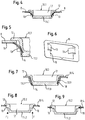
- component 10.1 For bracing the component 10.1 with the cover 4 are made of spring steel existing tongue-like clamping means 13, which are resiliently clamped and curving between the underside of the surface 8 of the cover 4 and undercuts 14 of the trough body 11.1, as in FIG. 5 illustrated by solid and dashed lines.
- the tensioning means 13 may be part of an in FIG. 6 shown as a detail clamping frame 15 which can be plugged with a cutout 16 on the trough body 11.1 with abutment on the surface 8 of the cover 4 and the clamping means 13 resiliently engage during Aufsteckvorgang in the undercuts 14.
- the components 10.1 and 10.2 ( Figure 8,9 ) have molded locking recesses 17 which occur in self-cleaning operation of the oven corresponding bolt of a locking device not shown and prevent opening of the oven door 1. These components can also serve that when closing the oven door 1, a housing-side electrical switch abuts the component and initiates a movement of the bolt in the locking recess 17.
- FIG. 7 are the tensioning means 13.1 directly part of the cover 4 and are in the undercuts 14 on the hollow body 10.1 bent it being possible to provide that in the region of the ends of the tensioning means 13.1 at position 18 elastic elements are attached, for example in the form of silicone grafts.
- FIGS. 8 and 9 Parts 19 of the hollow body 10.2 after its insertion into the recess 9 (FIG. FIG. 3 ) by printing an embossing stamp in the direction of arrow F with the underside of the cover 4 according to FIG. 1 imprinted so that a fixed connection of 10.2 and cover 4 is made.
Landscapes
- Engineering & Computer Science (AREA)
- Chemical & Material Sciences (AREA)
- Combustion & Propulsion (AREA)
- Mechanical Engineering (AREA)
- General Engineering & Computer Science (AREA)
- Electric Ovens (AREA)
- Furnace Housings, Linings, Walls, And Ceilings (AREA)
- Baking, Grill, Roasting (AREA)
Description
- Die Erfindung bezieht sich auf einen Backofen mit einer Ofentür und mit einer Verriegelungseinrichtung zum Verriegeln der geschlossenen Ofentür gegenüber dem Gehäuse des Backofens mittels eines motorisch verstellbaren gehäuseseitigen Riegels, der in der Verriegelungsstellung in ein Sperrelement an der Ofentür anschlagbegrenzt eingreift.
- Bei Backöfen insbesondere mit einer Einrichtung zur pyrolytischen Selbstreinigung der Garrraumwände ist es notwendig und vorgeschrieben, eine Verriegelungseinrichtung vorzusehen, mit welcher im Hitzereinigungsbetrieb mittels eines motorisch angetriebenen Riegels die geschlossene Ofentür verriegelt wird, so dass ein unbeabsichtigtes Öffnen derselben nicht möglich ist, wobei der Riegel mit dem Verstellen in die Verriegelungsposition anschlagbegrenzt in ein Sperrelement an der Ofentür eingreift und nach Prozessende und nach entsprechender Abkühlung des erhitzten Garraums die Ofentür wieder frei gibt. Das Dokument
EP0617235A offenbart einen Backofen mit den Merkmalen der Präambel. - Der Erfindung liegt die Aufgabe zugrunde einen Backofen der Eingangs genannten Art hinsichtlich des türseitigen Sperrelements so auszugestalten, dass bei einfacher Herstellung auch bei extremer thermischer Belastung des üblichen Einsatzbereiches des Sperrelementes an der oberen Begrenzung der Ofentür dessen Maßhaltigkeit und insbesondere Passgenauigkeit zu Riegel und Ofentür nicht beeinträchtigt wird.
- Diese Aufgabe wird bei einem Backofen der Eingangs genannten Art durch die Merkmale des Anspruchs 1 gelöst. Durch die Anordnung eines vorzugsweise als Aluminium-Druckgussteil ausgebildeten massiven Bauteils für die Sperrmulde der Verriegelungseinrichtung und dessen verspannten Einbau in die vorzugsweise aus Edelstahl bestehende Einfassung der Ofentür wird zum einen auch unter ungünstigen thermischen Verhältnissen eine hohe Maßhaltigkeit und Passgenauigkeit und damit ein hohes Kooperationspotential bezüglich der Verriegelungsfunktion erzielt und zum Beispiel bei längerem Gebrauch eine allmählich nachlassende Verbindungsfestigkeit und damit z.B: störende Klappergeräusche beim bewegen der Ofentür vermieden.
- Vorzugsweise ist das Bauteil in einer metallischen, an der Oberseite der Ofentür angeordneten Einfassung vorzugsweise in einer die Oberseite der Ofentür begrenzenden Abdeckung verspannt. Besondere Vorteile ergeben sich hierbei für die Serienproduktion des Backofens, in der als vorgefertigtes Zwischenprodukt die komplette Abdeckung mitsamt den zum Beispiel beidseitig der Abdeckung montierten Bauteilen hergestellt werden kann.
- Gemäß einer vorteilhaften Ausgestaltung der Erfindung ist das Bauteil als Betätigungselement für einen bei Verschließen der Ofentür zu betätigenden und die Verriegelungseinrichtung startenden elektrischen Schalter ausgebildet.
- Eine vorteilhafte Weiterbildung der Erfindung ist dadurch gegeben, dass das Bauteil einen die Sperrmulde aufweisenden, in die Ausnehmung der Einfassung der Ofentür einsteckbaren Muldenkörper und einen an der Einfassung anschlagenden Kragen aufweist und dass vorzugsweise ein Paar von federnden Spannmitteln vorgesehen ist, von denen jedes Spannmittel sich einerseits an der Einfassung der Ofentür und andererseits unter Vorspannung am Muldenkörper fixiert ist. Auf diese Weise wird dauerhaft eine ausreichende Verbindungsfestigkeit zwischen dem Bauteil und der sie tragenden Einfassung zum Beispiel in Form der die Oberseite der Ofentür begrenzenden Abdeckung gewährleistet. Als besonders vorteilhaft hat sich erwiesen, wenn die Spannmittel Bestandteile eines aus Federmaterial bestehenden Spannrahmens sind, der auf den Muldenkörper aufsteckbar ist und welcher sich einerseits an der Einfassung abstützt und deren federnde zungenartige Spannmittel andererseits in Hinterschneidungen des Muldenkörpers mit Vorspannung gehalten sind. Die vorzugsweise an zwei gegenüberliegenden Seiten des Bauteils bzw. dessen Muldenkörper angeordneten federnden Spannmittel können damit in einem einzigen Montagevorgang mit Einfassung und Bauteil verbunden werden, wobei die freiragenden, zungenartigen Spannmittel gleichzeitig in den Hinterschneidungen des Muldenkörpers mit einer vorbestimmten Federkraft verrasten.
- In einer Abwandelung des vorgenannten Erfindungsgedankens sind die zungenartigen Spannmittel aus dem Material der Einfassung geprägt und sind in Hinterschneidungen des Muldenkörpers fixiert. Damit erübrigt sich ein separates Federbauelement. Sollte die Federspannung der zungenartigen Spannmittel nicht ausreichen, so ist es vorteilhaft, wenn im Bereich der in den Hinterschneidungen liegenden zungenartigen Spannmittel federnde bzw. elastische Elemente vorzugsweise aus elastisch bleibenden Kunststoff zum Beispiel Silikon vorgesehen sind.
- Die Erfindung ist an Hand von in der Zeichnung dargestellten Ausführungsbeispielen nachstehend erläutert.
- Es zeigt:
- Figur 1
- die perspektivische Rückansicht der Ofentür für einen nicht dargestellten Backofen ,
- Figur 2
- eine vergrößerte Teilansicht des obersten Bereiches der Ofentür gemäß
Figur 1 , - Figur 3
- die die obere Begrenzung der Ofentür bildende metallische Abdeckung in perspektivischer Darstellung und als Einzelheit,
- Figur 4,5,6
- ein erstes Ausführungsbeispiel der Verbindung eines Bauteils und der Einfassung der Ofentür in Schnittdarstellung, vergrößerter Teilansicht und Einzelteildarstellung,
- Figur 7
- eine alternative Verbindungsweise zu
Figur 4-6 in Schnittansicht, - Figur 8,9
- eine weitere Ausführungsform hinsichtlich der Verbindungsweise von Bauteil und Einfassung der Ofentür in aufeinander folgenden Arbeitsschritten, dargestellt jeweils in Schnittansicht.
- Die Ofentür 1 gemäß den Figuren besteht im wesentlichen aus einer frontseitigen Glasscheibe 2 und einer einen Garraum begrenzenden inneren, napfartig geformten Glasscheibe 3, die einen Hohlraum begrenzen, in dem Mittel, zum Beispiel weitere Scheiben oder Platten angeordnet sind um einen Durchtritt von aus dem Garraum herkommender Wärmeenergie bis zur frontseitigen Glasscheibe 2 zumindest zu behindern.
- Der genannte Hohlraum und damit die Ofentür 1 wird nach oben hin begrenzt durch eine die Ofentür 1 überziehende Einfassung 4 in Form einer metallischen Abdeckung 4 aus Edelstahl, welche Abdeckung die Oberseite der Ofentür 1 bildet und mittels Schraubverbindung bei 5 befestigt ist an metallischen, beidseitig der Ofentür 1 senkrecht angeordneten Verbindungsholmen 6.
- Die Abdeckung 4 besitzt mehrere Luftaustrittsöffnungen 7 für die Abführung der im genannten Hohlraum der Ofentür 1 befindlichen erhitzten Luft ins Freie durch natürliche und/oder erzwungene Konvektion. Beidseitig der Luftaustrittsöffnungen 7 sind in die nach Innen hin schräg geneigte Fläche 8 der Abdeckung 4 rechteckige Ausnehmungen 9 eingearbeitet, in welche als Aluminium-Druckgussteile ausgebildete Bauteile 10 eingesteckt und darin in nachstehend beschriebener Weise verspannt sind.
- Das in den
Figuren 4 und 5 gezeigte Bauteil 10.1 besitzt einen quaderförmigen Muldenkörper 11.1, der in die Ausnehmung 9 der Fläche 8 einsteckbar ist und mit einem umlaufenden Kragen 12 an der Oberseite der Fläche 8 anliegt und sich daran abstützt. Zur Verspannung des Bauteils 10.1 mit der Abdeckung 4 dienen aus Federstahl bestehende zungenartige Spannmittel 13, die zwischen der Unterseite der Fläche 8 der Abdeckung 4 und in Hinterschneidungen 14 des Muldenkörpers 11.1 federnd und sich krümmend verspannt sind, wie inFigur 5 durch ausgezogene und gestrichelte Linienzüge verdeutlicht. Die Spannmittel 13 können Bestandteil eines inFigur 6 als Einzelheit dargestellten Spannrahmens 15 sein der mit einem Ausschnitt 16 auf den Muldenkörper 11.1 mit Anlage an der Fläche 8 der Abdeckung 4 aufsteckbar ist und deren Spannmittel 13 beim Aufsteckvorgang in den Hinterschneidungen 14 federnd verrasten. - Die Bauteile 10.1 und 10.2 (
Figur 8,9 ) besitzen eingeformte Sperrmulden 17 in welche bei Selbstreinigungsbetrieb des Backofens entsprechende Riegel einer nicht weiter dargestellten Verriegelungseinrichtung einfallen und ein Öffnen der Ofentür 1 verhindern. Diese Bauteile können auch dazu dienen, dass beim Verschließen der Ofentür 1 ein gehäuseseitiger elektrischer Schalter am Bauteil anschlägt und eine Bewegung des Riegels in die Sperrmulde 17 einleitet. - Beim Ausführungsbeispiel gemäß
Figur 7 sind die Spannmittel 13.1 unmittelbarer Bestandteil der Abdeckung 4 und werden in die Hinterschneidungen 14 am Muldenkörper 10.1 gebogen wobei vorgesehen sein kann, dass im Bereich der Enden der Spannmittel 13.1 bei Position 18 elastische Elemente zum Beispiel in Form von Silikon-Pfropfen angebracht werden. - Gemäß
Figur 8 und 9 werden Teile 19 des Muldenkörpers 10.2 nach dessen Einfügung in die Ausnehmung 9 (Figur 3 ) durch Druck eines Prägestempels in Pfeilrichtung F mit der Unterseite der Abdeckung 4 gemäßFigur 1 verprägt sodass eine feste Verbindung von 10.2 und Abdeckung 4 hergestellt ist.
Claims (10)
- Backofen mit einer Ofentür (1) und mit einer Verriegelungseinrichtung zum Verriegeln der geschlossenen Ofentür (1) gegenüber dem Gehäuse des Backofens mit Hilfe eines motorisch verstellbaren gehäuseseitigen Riegels, der in der Verriegelungsstellung in ein Sperrelement (17) an der Ofentür (1) anschlagbegrenzt eingreift, wobei das Sperrelement als in eine Ausnehmung (9) der Einfassung (4) der Ofentür (1) einsteckbares Bauteil (10.1, 10.2) ausgebildet ist, dadurch gekennzeichnet, dass das Sperrelement in der Ausnehmung (9) mittels Spannmitteln (13, 19) verspannbar ist.
- Backofen nach Anspruch 1, dadurch gekennzeichnet, dass das Bauteil (10.1, 10.2) in einer metallischen, an der Oberseite der Ofentür (1) angeordneten Einfassung, vorzugsweise in einer die Oberseite der Ofentür (1) begrenzenden Abdeckung (4) verspannt ist.
- Backofen nach einem der vorhergehenden Ansprüche, dadurch gekennzeichnet, dass das Bauteil (10.1,10.2) als aus Aluminium bestehendes Druckgussteil ausgebildet ist.
- Backofen nach einem der vorhergehenden Ansprüche, dadurch gekennzeichnet, dass das Bauteil (10.1,10.2) eine in der Verriegelungsstellung den Riegel anschlagbegrenzt aufnehmende Sperrmulde (17) aufweist.
- Backofen nach einem der vorhergehenden Ansprüche, dadurch gekennzeichnet, dass das Bauteil (10.1,10.2) als Betätigungselement für einen bei Verschließen der Ofentür (1) zu betätigenden und die Verriegelungseinrichtung startenden elektrischen Schalter ausgebildet ist.
- Backofen nach Anspruch 4, dadurch gekennzeichnet, dass das Bauteil (10.1) einen die Sperrmulde (17) aufweisenden, in die Ausnehmung (9) der Einfassung der Ofentür(1) einsteckbaren Muldenkörper (11.1,11.2) und einen an der Einfassung (4) anschlagenden Kragen (12) aufweist und dass ein Paar von federnden Spannmitteln (13,13.1)) vorgesehen sind, von denen jedes Spannmittel einerseits an der Einfassung (4) der Ofentür (1) und andererseits unter Vorspannung am Muldenkörper (11.1) fixiert ist.
- Backofen nach einem der vorhergehenden Ansprüche, dadurch gekennzeichnet, dass die Spannmittel (13) Bestandteil eines aus Federmaterial bestehenden Spannrahmens (15) sind, der auf den Muldenkörper (11.1) aufsteckbar ist und welcher sich einerseits an der Einfassung (4) abstützt und deren federnde zungenartige Spannmittel (13) andererseits in Hinterschneidungen (14) des Muldenkörpers (11.1) mit Vorspannung gehalten sind.
- Backofen nach Anspruch 6, dadurch gekennzeichnet, dass die zungenartigen Spannmittel (13.1) aus dem Material der Einfassung (4) geprägt sind und in Hinterschneidungen des Muldenkörpers (11.1) fixiert sind.
- Backofen nach Anspruch 8, dadurch gekennzeichnet, dass im Bereich der in den Hinterschneidungen (14) liegenden zungenartigen Spannmittel (13.1) federnde bzw. elastische Elemente (18) vorzugsweise aus elastisch bleibendem Kunststoff zum Beispiel Silikon vorgesehen sind.
- Backofen nach einem der vorhergehenden Ansprüche, dadurch gekennzeichnet, dass das Bauteil (10.2) einen die Sperrmulde (4) aufweisenden, in die Ausnehmung (9) der Ofentür (1) anschlagbegrenzt einsteckbaren Muldenkörper (11.2) aufweist und ein Teil des eingesteckten Muldenkörpers mit der Einfassung (4) verprägt ist.
Applications Claiming Priority (1)
| Application Number | Priority Date | Filing Date | Title |
|---|---|---|---|
| DE102006042177A DE102006042177A1 (de) | 2006-09-08 | 2006-09-08 | Backofen |
Publications (3)
| Publication Number | Publication Date |
|---|---|
| EP1901006A2 EP1901006A2 (de) | 2008-03-19 |
| EP1901006A3 EP1901006A3 (de) | 2016-09-14 |
| EP1901006B1 true EP1901006B1 (de) | 2017-12-13 |
Family
ID=38637927
Family Applications (1)
| Application Number | Title | Priority Date | Filing Date |
|---|---|---|---|
| EP07114723.5A Not-in-force EP1901006B1 (de) | 2006-09-08 | 2007-08-22 | Backofen |
Country Status (2)
| Country | Link |
|---|---|
| EP (1) | EP1901006B1 (de) |
| DE (1) | DE102006042177A1 (de) |
Cited By (1)
| Publication number | Priority date | Publication date | Assignee | Title |
|---|---|---|---|---|
| EP2553343B1 (de) | 2010-04-01 | 2018-05-30 | Electrolux Home Products Corporation N.V. | Ofentüre, sowie verfahren zum befestigen eines türabdeckteils an einer derartigen ofentüre |
Families Citing this family (2)
| Publication number | Priority date | Publication date | Assignee | Title |
|---|---|---|---|---|
| DE102014216548A1 (de) | 2014-03-19 | 2015-09-24 | BSH Hausgeräte GmbH | Tür für ein Haushaltsgerät und eine als Hybrid-Bauteil ausgebildete Abdeckung für zumindest eine Türscheibe sowie Haushaltsgerät mit einer derartigen Tür |
| EP2933567B1 (de) * | 2014-04-08 | 2019-08-28 | Whirlpool EMEA S.p.A | Kochherd für den haushalt |
Family Cites Families (7)
| Publication number | Priority date | Publication date | Assignee | Title |
|---|---|---|---|---|
| FR2703137B1 (fr) * | 1993-03-23 | 1995-04-28 | Cepem | Dispositif de verrouillage de la porte d'un four. |
| FR2756615A1 (fr) * | 1996-11-29 | 1998-06-05 | Soremam | Dispositif de verrouillage de la porte d'un four, en particulier d'un four autonettoyant a pyrolyse |
| GB2354795A (en) * | 1999-09-29 | 2001-04-04 | Silicone Altimex Ltd | Oven door catch |
| DE10108724B4 (de) * | 2001-02-23 | 2004-07-01 | AEG Hausgeräte GmbH | Verriegelungseinrichtung für die Tür eines Haushhaltsgerätes, insbesondere Haushaltsgargerätes |
| US6863316B2 (en) * | 2001-12-21 | 2005-03-08 | Emerson Electric Co. | Door latch mechanism and associated components for a self-cleaning oven |
| DE10259058A1 (de) * | 2002-12-17 | 2004-07-01 | BSH Bosch und Siemens Hausgeräte GmbH | Gargerätetür |
| US7137387B2 (en) * | 2004-06-25 | 2006-11-21 | Emerson Electric Co. | Oven lock with mechanical actuation of remotely located door switch |
-
2006
- 2006-09-08 DE DE102006042177A patent/DE102006042177A1/de not_active Withdrawn
-
2007
- 2007-08-22 EP EP07114723.5A patent/EP1901006B1/de not_active Not-in-force
Non-Patent Citations (1)
| Title |
|---|
| None * |
Cited By (2)
| Publication number | Priority date | Publication date | Assignee | Title |
|---|---|---|---|---|
| EP2553343B1 (de) | 2010-04-01 | 2018-05-30 | Electrolux Home Products Corporation N.V. | Ofentüre, sowie verfahren zum befestigen eines türabdeckteils an einer derartigen ofentüre |
| EP2553343B2 (de) † | 2010-04-01 | 2022-03-30 | Electrolux Home Products Corporation N.V. | Ofentüre, sowie verfahren zum befestigen eines türabdeckteils an einer derartigen ofentüre |
Also Published As
| Publication number | Publication date |
|---|---|
| EP1901006A2 (de) | 2008-03-19 |
| EP1901006A3 (de) | 2016-09-14 |
| DE102006042177A1 (de) | 2008-03-27 |
Similar Documents
| Publication | Publication Date | Title |
|---|---|---|
| EP1878484B1 (de) | Luftdurchtrittsvorrichtung | |
| EP3551938B1 (de) | Haushaltsgargerät | |
| EP1505352A2 (de) | Tür für ein Haushaltsgerät mit demontierbarer Scheibe | |
| DE10341847B4 (de) | Einbaukochmulde | |
| EP1901006B1 (de) | Backofen | |
| DE102013204084A1 (de) | Dunstabzugsvorrichtung, insbesondere Muldenlüftungsvorrichtung | |
| EP1217306B1 (de) | Backofen mit Wrasenkanal | |
| DE10163149A1 (de) | Gerätetür,vorzugsweise für ein Haushaltgerät | |
| EP1687571B1 (de) | Haushaltsgerät mit einer bedienleiste | |
| EP1126126A1 (de) | Backofentür mit Sichtfenster und Betätigungshandgriff | |
| EP1788313A2 (de) | Auszugsvorrichtung für ein Haushaltsgerät | |
| EP2378209B1 (de) | Dunstabzugshaube | |
| DE202006010888U1 (de) | Luftdurchtrittsvorrichtung | |
| DE19923487B4 (de) | Widerlager mit Formteil zum Befestigen von Betätigungszügen | |
| DE10143923C2 (de) | Gargerätetür | |
| DE10219349A1 (de) | Tür für ein Gerät, insbesondere für einen Garofen | |
| EP2444737A1 (de) | Vorrichtung zur Ausblasung von Wrasen aus einem Gargerät sowie Gargerät mit einer derartigen Vorrichtung | |
| DE10143926A1 (de) | Gargerätetür | |
| EP3141820A1 (de) | Tür für ein haushaltsgerät und eine als hybrid-bauteil ausgebildete abdeckung für zumindest eine türscheibe sowie haushaltsgerät mit einer derartigen tür | |
| EP1918645B1 (de) | Garofentür | |
| DE102016202777A1 (de) | Lagerbuchse für ein Haushaltsgerät mit einem Federelement, welches ein Abdeckteil zum Abdecken einer Einfädelöffnung aufweist, Baugruppe sowie Haushaltsgerät | |
| EP1526335B1 (de) | Kochfeld | |
| EP1648203B1 (de) | Verfahren zur Positionierung und Arretierung einer drehbar gelagerten Ofentür eines Mikrowellenofens sowie Mikrowellenofen | |
| EP1632723B1 (de) | Montagesystem für eine an einer Wand befestigbare Dunstabzugshaube | |
| DE102017207472A1 (de) | Filtereinheit für eine Dunstabzugshaube und Dunstabzugshaube |
Legal Events
| Date | Code | Title | Description |
|---|---|---|---|
| PUAI | Public reference made under article 153(3) epc to a published international application that has entered the european phase |
Free format text: ORIGINAL CODE: 0009012 |
|
| AK | Designated contracting states |
Kind code of ref document: A2 Designated state(s): AT BE BG CH CY CZ DE DK EE ES FI FR GB GR HU IE IS IT LI LT LU LV MC MT NL PL PT RO SE SI SK TR |
|
| AX | Request for extension of the european patent |
Extension state: AL BA HR MK YU |
|
| RAP1 | Party data changed (applicant data changed or rights of an application transferred) |
Owner name: BSH HAUSGERAETE GMBH |
|
| PUAL | Search report despatched |
Free format text: ORIGINAL CODE: 0009013 |
|
| AK | Designated contracting states |
Kind code of ref document: A3 Designated state(s): AT BE BG CH CY CZ DE DK EE ES FI FR GB GR HU IE IS IT LI LT LU LV MC MT NL PL PT RO SE SI SK TR |
|
| AX | Request for extension of the european patent |
Extension state: AL BA HR MK RS |
|
| RIC1 | Information provided on ipc code assigned before grant |
Ipc: F24C 15/02 20060101AFI20160810BHEP |
|
| 17P | Request for examination filed |
Effective date: 20170314 |
|
| RBV | Designated contracting states (corrected) |
Designated state(s): AT BE BG CH CY CZ DE DK EE ES FI FR GB GR HU IE IS IT LI LT LU LV MC MT NL PL PT RO SE SI SK TR |
|
| AKX | Designation fees paid |
Designated state(s): AT BE BG CH CY CZ DE DK EE ES FI FR GB GR HU IE IS IT LI LT LU LV MC MT NL PL PT RO SE SI SK TR |
|
| AXX | Extension fees paid |
Extension state: HR Extension state: AL Extension state: BA Extension state: RS Extension state: MK |
|
| GRAP | Despatch of communication of intention to grant a patent |
Free format text: ORIGINAL CODE: EPIDOSNIGR1 |
|
| INTG | Intention to grant announced |
Effective date: 20170726 |
|
| GRAS | Grant fee paid |
Free format text: ORIGINAL CODE: EPIDOSNIGR3 |
|
| GRAA | (expected) grant |
Free format text: ORIGINAL CODE: 0009210 |
|
| AK | Designated contracting states |
Kind code of ref document: B1 Designated state(s): AT BE BG CH CY CZ DE DK EE ES FI FR GB GR HU IE IS IT LI LT LU LV MC MT NL PL PT RO SE SI SK TR |
|
| REG | Reference to a national code |
Ref country code: GB Ref legal event code: FG4D Free format text: NOT ENGLISH |
|
| REG | Reference to a national code |
Ref country code: AT Ref legal event code: REF Ref document number: 954773 Country of ref document: AT Kind code of ref document: T Effective date: 20171215 Ref country code: CH Ref legal event code: EP |
|
| REG | Reference to a national code |
Ref country code: IE Ref legal event code: FG4D Free format text: LANGUAGE OF EP DOCUMENT: GERMAN |
|
| REG | Reference to a national code |
Ref country code: DE Ref legal event code: R096 Ref document number: 502007015980 Country of ref document: DE |
|
| REG | Reference to a national code |
Ref country code: NL Ref legal event code: MP Effective date: 20171213 |
|
| REG | Reference to a national code |
Ref country code: LT Ref legal event code: MG4D |
|
| PG25 | Lapsed in a contracting state [announced via postgrant information from national office to epo] |
Ref country code: FI Free format text: LAPSE BECAUSE OF FAILURE TO SUBMIT A TRANSLATION OF THE DESCRIPTION OR TO PAY THE FEE WITHIN THE PRESCRIBED TIME-LIMIT Effective date: 20171213 Ref country code: LT Free format text: LAPSE BECAUSE OF FAILURE TO SUBMIT A TRANSLATION OF THE DESCRIPTION OR TO PAY THE FEE WITHIN THE PRESCRIBED TIME-LIMIT Effective date: 20171213 Ref country code: SE Free format text: LAPSE BECAUSE OF FAILURE TO SUBMIT A TRANSLATION OF THE DESCRIPTION OR TO PAY THE FEE WITHIN THE PRESCRIBED TIME-LIMIT Effective date: 20171213 |
|
| PG25 | Lapsed in a contracting state [announced via postgrant information from national office to epo] |
Ref country code: BG Free format text: LAPSE BECAUSE OF FAILURE TO SUBMIT A TRANSLATION OF THE DESCRIPTION OR TO PAY THE FEE WITHIN THE PRESCRIBED TIME-LIMIT Effective date: 20180313 Ref country code: GR Free format text: LAPSE BECAUSE OF FAILURE TO SUBMIT A TRANSLATION OF THE DESCRIPTION OR TO PAY THE FEE WITHIN THE PRESCRIBED TIME-LIMIT Effective date: 20180314 Ref country code: LV Free format text: LAPSE BECAUSE OF FAILURE TO SUBMIT A TRANSLATION OF THE DESCRIPTION OR TO PAY THE FEE WITHIN THE PRESCRIBED TIME-LIMIT Effective date: 20171213 |
|
| PG25 | Lapsed in a contracting state [announced via postgrant information from national office to epo] |
Ref country code: NL Free format text: LAPSE BECAUSE OF FAILURE TO SUBMIT A TRANSLATION OF THE DESCRIPTION OR TO PAY THE FEE WITHIN THE PRESCRIBED TIME-LIMIT Effective date: 20171213 |
|
| PG25 | Lapsed in a contracting state [announced via postgrant information from national office to epo] |
Ref country code: ES Free format text: LAPSE BECAUSE OF FAILURE TO SUBMIT A TRANSLATION OF THE DESCRIPTION OR TO PAY THE FEE WITHIN THE PRESCRIBED TIME-LIMIT Effective date: 20171213 Ref country code: SK Free format text: LAPSE BECAUSE OF FAILURE TO SUBMIT A TRANSLATION OF THE DESCRIPTION OR TO PAY THE FEE WITHIN THE PRESCRIBED TIME-LIMIT Effective date: 20171213 Ref country code: EE Free format text: LAPSE BECAUSE OF FAILURE TO SUBMIT A TRANSLATION OF THE DESCRIPTION OR TO PAY THE FEE WITHIN THE PRESCRIBED TIME-LIMIT Effective date: 20171213 Ref country code: CY Free format text: LAPSE BECAUSE OF FAILURE TO SUBMIT A TRANSLATION OF THE DESCRIPTION OR TO PAY THE FEE WITHIN THE PRESCRIBED TIME-LIMIT Effective date: 20171213 Ref country code: CZ Free format text: LAPSE BECAUSE OF FAILURE TO SUBMIT A TRANSLATION OF THE DESCRIPTION OR TO PAY THE FEE WITHIN THE PRESCRIBED TIME-LIMIT Effective date: 20171213 |
|
| REG | Reference to a national code |
Ref country code: FR Ref legal event code: PLFP Year of fee payment: 12 |
|
| PG25 | Lapsed in a contracting state [announced via postgrant information from national office to epo] |
Ref country code: IS Free format text: LAPSE BECAUSE OF FAILURE TO SUBMIT A TRANSLATION OF THE DESCRIPTION OR TO PAY THE FEE WITHIN THE PRESCRIBED TIME-LIMIT Effective date: 20180413 Ref country code: PL Free format text: LAPSE BECAUSE OF FAILURE TO SUBMIT A TRANSLATION OF THE DESCRIPTION OR TO PAY THE FEE WITHIN THE PRESCRIBED TIME-LIMIT Effective date: 20171213 Ref country code: IT Free format text: LAPSE BECAUSE OF FAILURE TO SUBMIT A TRANSLATION OF THE DESCRIPTION OR TO PAY THE FEE WITHIN THE PRESCRIBED TIME-LIMIT Effective date: 20171213 Ref country code: RO Free format text: LAPSE BECAUSE OF FAILURE TO SUBMIT A TRANSLATION OF THE DESCRIPTION OR TO PAY THE FEE WITHIN THE PRESCRIBED TIME-LIMIT Effective date: 20171213 |
|
| REG | Reference to a national code |
Ref country code: DE Ref legal event code: R097 Ref document number: 502007015980 Country of ref document: DE |
|
| PG25 | Lapsed in a contracting state [announced via postgrant information from national office to epo] |
Ref country code: MT Free format text: LAPSE BECAUSE OF FAILURE TO SUBMIT A TRANSLATION OF THE DESCRIPTION OR TO PAY THE FEE WITHIN THE PRESCRIBED TIME-LIMIT Effective date: 20171213 |
|
| PLBE | No opposition filed within time limit |
Free format text: ORIGINAL CODE: 0009261 |
|
| STAA | Information on the status of an ep patent application or granted ep patent |
Free format text: STATUS: NO OPPOSITION FILED WITHIN TIME LIMIT |
|
| 26N | No opposition filed |
Effective date: 20180914 |
|
| PG25 | Lapsed in a contracting state [announced via postgrant information from national office to epo] |
Ref country code: DK Free format text: LAPSE BECAUSE OF FAILURE TO SUBMIT A TRANSLATION OF THE DESCRIPTION OR TO PAY THE FEE WITHIN THE PRESCRIBED TIME-LIMIT Effective date: 20171213 |
|
| PG25 | Lapsed in a contracting state [announced via postgrant information from national office to epo] |
Ref country code: SI Free format text: LAPSE BECAUSE OF FAILURE TO SUBMIT A TRANSLATION OF THE DESCRIPTION OR TO PAY THE FEE WITHIN THE PRESCRIBED TIME-LIMIT Effective date: 20171213 |
|
| PG25 | Lapsed in a contracting state [announced via postgrant information from national office to epo] |
Ref country code: MC Free format text: LAPSE BECAUSE OF FAILURE TO SUBMIT A TRANSLATION OF THE DESCRIPTION OR TO PAY THE FEE WITHIN THE PRESCRIBED TIME-LIMIT Effective date: 20171213 |
|
| REG | Reference to a national code |
Ref country code: CH Ref legal event code: PL |
|
| GBPC | Gb: european patent ceased through non-payment of renewal fee |
Effective date: 20180822 |
|
| PG25 | Lapsed in a contracting state [announced via postgrant information from national office to epo] |
Ref country code: LU Free format text: LAPSE BECAUSE OF NON-PAYMENT OF DUE FEES Effective date: 20180822 Ref country code: CH Free format text: LAPSE BECAUSE OF NON-PAYMENT OF DUE FEES Effective date: 20180831 Ref country code: LI Free format text: LAPSE BECAUSE OF NON-PAYMENT OF DUE FEES Effective date: 20180831 |
|
| REG | Reference to a national code |
Ref country code: BE Ref legal event code: MM Effective date: 20180831 |
|
| PG25 | Lapsed in a contracting state [announced via postgrant information from national office to epo] |
Ref country code: BE Free format text: LAPSE BECAUSE OF NON-PAYMENT OF DUE FEES Effective date: 20180831 |
|
| REG | Reference to a national code |
Ref country code: AT Ref legal event code: MM01 Ref document number: 954773 Country of ref document: AT Kind code of ref document: T Effective date: 20180822 |
|
| PG25 | Lapsed in a contracting state [announced via postgrant information from national office to epo] |
Ref country code: GB Free format text: LAPSE BECAUSE OF NON-PAYMENT OF DUE FEES Effective date: 20180822 |
|
| PGFP | Annual fee paid to national office [announced via postgrant information from national office to epo] |
Ref country code: DE Payment date: 20190831 Year of fee payment: 13 Ref country code: FR Payment date: 20190822 Year of fee payment: 13 |
|
| PG25 | Lapsed in a contracting state [announced via postgrant information from national office to epo] |
Ref country code: AT Free format text: LAPSE BECAUSE OF NON-PAYMENT OF DUE FEES Effective date: 20180822 |
|
| PG25 | Lapsed in a contracting state [announced via postgrant information from national office to epo] |
Ref country code: TR Free format text: LAPSE BECAUSE OF FAILURE TO SUBMIT A TRANSLATION OF THE DESCRIPTION OR TO PAY THE FEE WITHIN THE PRESCRIBED TIME-LIMIT Effective date: 20171213 |
|
| PG25 | Lapsed in a contracting state [announced via postgrant information from national office to epo] |
Ref country code: HU Free format text: LAPSE BECAUSE OF FAILURE TO SUBMIT A TRANSLATION OF THE DESCRIPTION OR TO PAY THE FEE WITHIN THE PRESCRIBED TIME-LIMIT; INVALID AB INITIO Effective date: 20070822 Ref country code: PT Free format text: LAPSE BECAUSE OF FAILURE TO SUBMIT A TRANSLATION OF THE DESCRIPTION OR TO PAY THE FEE WITHIN THE PRESCRIBED TIME-LIMIT Effective date: 20171213 |
|
| PG25 | Lapsed in a contracting state [announced via postgrant information from national office to epo] |
Ref country code: IE Free format text: LAPSE BECAUSE OF NON-PAYMENT OF DUE FEES Effective date: 20180822 |
|
| REG | Reference to a national code |
Ref country code: DE Ref legal event code: R119 Ref document number: 502007015980 Country of ref document: DE |
|
| PG25 | Lapsed in a contracting state [announced via postgrant information from national office to epo] |
Ref country code: FR Free format text: LAPSE BECAUSE OF NON-PAYMENT OF DUE FEES Effective date: 20200831 Ref country code: DE Free format text: LAPSE BECAUSE OF NON-PAYMENT OF DUE FEES Effective date: 20210302 |