EP1901311B1 - Corps en élastomère réticulé - Google Patents
Corps en élastomère réticulé Download PDFInfo
- Publication number
- EP1901311B1 EP1901311B1 EP07018009A EP07018009A EP1901311B1 EP 1901311 B1 EP1901311 B1 EP 1901311B1 EP 07018009 A EP07018009 A EP 07018009A EP 07018009 A EP07018009 A EP 07018009A EP 1901311 B1 EP1901311 B1 EP 1901311B1
- Authority
- EP
- European Patent Office
- Prior art keywords
- electrically conductive
- conductive filler
- strain
- elastomer
- volume fraction
- Prior art date
- Legal status (The legal status is an assumption and is not a legal conclusion. Google has not performed a legal analysis and makes no representation as to the accuracy of the status listed.)
- Not-in-force
Links
Images




Classifications
-
- H—ELECTRICITY
- H01—ELECTRIC ELEMENTS
- H01B—CABLES; CONDUCTORS; INSULATORS; SELECTION OF MATERIALS FOR THEIR CONDUCTIVE, INSULATING OR DIELECTRIC PROPERTIES
- H01B1/00—Conductors or conductive bodies characterised by the conductive materials; Selection of materials as conductors
- H01B1/20—Conductive material dispersed in non-conductive organic material
- H01B1/24—Conductive material dispersed in non-conductive organic material the conductive material comprising carbon-silicon compounds, carbon or silicon
Definitions
- the present invention relates to a crosslinked elastomer body to be used as a material for a sensor of a resistance increasing type which is designed such that a resistance observed under compressive strain or bending strain increases according to the strain, and to a production method for the crosslinked elastomer body.
- inorganic strain sensors employing inorganic materials typified by piezoceramic materials are used for detecting stress, acceleration, vibrations and deformation (strain) exerted on a component.
- an inorganic strain sensor is generally made of a highly rigid material, so that the shape design flexibility of the sensor is limited.
- a specific sensor material system should be selected and prepared depending on a measurement range of surface pressure, strain, acceleration or the like. Therefore, the advent of a strain sensor capable of sensing a wider measurement range of a physical quantity with the use of the same material system is long-awaited.
- elastomers are employed instead of the inorganic materials, and a variety of pressure-sensitive electrically-conductive elastomeric materials are proposed which are each prepared by combining an elastomer with an electrically conductive filler (see, for example, Japanese Unexamined Patent Publication No. HEI3(1991)-93109 ).
- the patent publication discloses a sensor of a so-called resistance reducing type which exhibits a higher electrical resistance under no strain but exhibits a reduced electrical resistance under compressive strain. More specifically, when the sensor is under compressive strain, inter-particle distances of the electrically conductive filler in the elastomeric material are reduced, so that electrical conduction paths are formed by the electrically conductive filler to reduce the resistance.
- the sensor suffers from significant variations in detection value (resistance value) with respect to the strain, because a resistance change responsive to the strain is not necessarily constant. In some cases, the sensor exhibits an increased electrical resistance under greater strain. This makes it difficult to provide stable measurement results.
- the variations in detection value with respect to the strain occur not only between different sensors but also in a single sensor. The sensor tends to suffer from wider variations in detection value when being deformed in different directions. With less reliable measurement results, the sensor fails to provide sufficiently high measurement accuracy required for industrial applications.
- a pressure-sensitive electrically-conductive elastomeric material for the resistance reducing type sensor disclosed in the patent publication significantly varies in detection sensitivity depending on the proportion of the electrically conductive filler blended in the elastomer. Therefore, it is difficult to impart the sensor with intended sensitivity and other measurement characteristics, making it very difficult to design and produce the sensor. Further, the sensor disclosed in the patent publication is simply adapted to detect a compressive deformation degree based on a change in DC resistance. After particles of the blended electrically conductive filler are brought into a certain contact state, the detection value hardly changes. Therefore, the sensor has a drawback such that the detection ranges of external force and stress are narrower.
- the pressure-sensitive electrically-conductive elastomeric materials of the prior art have resistance reducing properties
- a pressure-sensitive electrically-conductive elastomeric material having a pressure-sensitive resistance increasing property is hitherto unknown.
- a crosslinked elastomer body which has a pressure-sensitive resistance increasing property, higher shape design flexibility and excellent moldability, and is capable of stably sensing a wider measurement range of a physical quantity when used for a sensor (a sensor of a resistance increasing type), and to provide a production method therefor.
- the objects are achieved by a crosslinked elastomer body according to claim 1, and a production method according to claim 6.
- Preferred embodiments are subject of dependent claims.
- a crosslinked elastomer body for a sensor which is composed of an electrically conductive composition comprising an electrically conductive filler and an insulative elastomer as essential components, wherein the electrically conductive filler is in a spherical particulate form and has an average particle diameter of 0.05 to 100 ⁇ m, wherein the electrically conductive filler has a critical volume fraction ( ⁇ c) of not less than 30 vol% as determined at a first inflection point of a percolation curve at which an insulator-conductor transition occurs with an electrical resistance steeply reduced when the electrically conductive filler is gradually added to the elastomer, wherein the electrically conductive filler is present in a volume fraction not less than the critical volume fraction ( ⁇ c) in the composition, whereby a resistance of the elastomer body observed under compressive strain or bending strain increases according to the strain as compared to a resistance of the
- a production method for producing the crosslinked elastomer body comprising the steps of: providing an electrically conductive filler of a spherical particulate form having an average particle diameter of 0.05 to 100 ⁇ m and an insulative elastomer; preparing an electrically conductive composition by mixing the electrically conductive filler and the elastomer as essential components and a vulcanizing agent as an optional component, the electrically conductive filler being present in a volume fraction of not less than 30 vol% in the electrically conductive composition; and forming the electrically conductive composition into a predetermined shape and then crosslinking the composition.
- the inventors of the present invention have conducted intensive studies to provide a crosslinked elastomer body which has a pressure-sensitive resistance increasing property, higher shape design flexibility and excellent moldability, and is capable of stably sensing a wider measurement range of a physical quantity when used for a sensor (a sensor of a resistance increasing type).
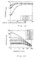
- Fig. 1 schematically illustrates a percolation curve showing a relationship between the volume fraction of an electrically conductive filler and the electrical resistance of an electrically conductive composition essentially containing the electrically conductive filler and an insulative elastomer.
- the electrically conductive filler 2 is gradually added to the insulative elastomer (matrix) 1, the electrical resistance of the resulting composition is substantially equal to that of the elastomer (matrix) 1 at the initial stage.
- the volume fraction of the electrically conductive filler 1 reaches a certain level (at a first inflection point of the percolation curve), an insulator-conductor transition occurs with the electrical resistance steeply reduced.
- the volume fraction of the electrically conductive filler 2 at the first inflection point is herein defined as a critical volume fraction ( ⁇ c)
- ⁇ c critical volume fraction
- the volume fraction of the electrically conductive filler 2 at the second inflection point is herein defined as a saturated volume fraction ( ⁇ s).
- an electrically conductive filler such as a carbon black
- the filler has a greater specific surface area and a greater inter-particle surface adsorption/agglomerationenergy. Therefore, several to several tens primary particles of the electrically conductive filler are agglomerated, so that the electrically conductive filler particles are less liable to be present in the form of primary particles in the elastomer.
- the electrically conductive filler having a smaller average particle diameter and hence liable to be present in the form of secondary particles tends to form an electrically conductive filler network structure in the elastomer.
- the electrically conductive filler causes a percolation phenomenon at a critical volume fraction ( ⁇ c) of about 20 vol % to be thereby imparted with electrical conductivity due to formation of continuous electrical conduction paths.
- ⁇ c critical volume fraction
- the electrically conductive filler is liable to agglomerate and hence has a lower percolation critical volume fraction ( ⁇ c)
- ⁇ c percolation critical volume fraction
- the pressure-sensitive electrically-conductive elastomeric material of the resistance reducing type on the other hand, an electrically conductive filler having a higher percolation critical volume fraction ( ⁇ c) and hence less liable to agglomerate is dispersed in the elastomer. Therefore, the pressure-sensitive electrically-conductive elastomer body serves as an insulator under no strain because of greater inter-particle distances of the electrically conductive filler, but serves as a conductor under compressive strain because of formation of continuous electrical conduction paths by the electrically conductive filler.
- the inventors of the present invention have conducted further studies to provide an elastomeric material having a pressure-sensitive resistance increasing property for improvement over the elastomeric material of the pressure-sensitive resistance reducing type and found, beyond common sense knowledge, that advantageous results are obtained by using a greater amount of a filler having a relatively large average particle diameter.
- an electrically conductive filler having a relatively large average particle diameter and expected to be mostly present in the form of primary particles in an elastomeric material and a crosslinked elastomer (matrix) having higher affinity for the filler are selected and the electrically conductive filler has a percolation critical volume fraction ( ⁇ c) of not less than 30 vol%, the filler can be dispersed in a non-agglomerated state in the elastomer.
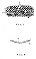
- the electrically conductive filler 2 is present substantially in the closest packed state in the crosslinked elastomer (matrix) 1 as shown in Fig. 2 . Therefore, when neither compressive strain nor bending strain is applied to the elastomer body, particles of the electrically conductive filler 2 are brought into contact with one another with the intervention of thin film-like elastomer portions (not shown), thereby forming three-dimensional electrical conduction paths (as indicated by arrows in Fig. 2 ).
- the elastomer body exhibits higher electrical conductivity (lower resistance).
- the packed state of the electrically conductive filler particles 2 is changed from the closest packed state due to spatial repulsion of the filler particles. Therefore, the electrically conductive filler particles 2 are brought out of contact with one another, so that the three-dimensional electrical conduction paths (indicated by the arrows in Fig. 2 ) are destroyed.
- the inventors of the present invention have found that a resistance observed under compressive strain or bending strain is increased according to the strain over a resistance observed under no strain and hence the electrical conductivity is reduced (with a higher resistance), and attained the present invention.
- the electrically conductive filler having a relatively great average particle diameter and expected to be mostly present in the form of primary particles in the elastomer and hence having a percolation critical volume fraction ( ⁇ c) of not less than 30 vol% is employed in combination with the crosslinked elastomer (matrix) having higher affinity for the filler. Therefore, the electrically conductive filler is dispersed in a non-agglomerated state in the elastomer, and is present at a high concentration, i.e., in a volume fraction (packing amount) not less than the critical volume fraction ( ⁇ c), in the elastomer.
- the electrically conductive filler particles are present substantially in the closest packed state in the crosslinked elastomer (matrix).
- the filler particles When neither compressive strain nor bending strain is applied to the elastomer body, the filler particles are brought into contact with one another with the intervention of thin film-like elastomer portions, thereby forming three-dimensional electrical conduction paths.
- the elastomer body exhibits higher electrical conductivity (lower resistance).
- the packed state of the electrically conductive filler particles is changed from the closest packed state due to spatial repulsion of the filler particles. Therefore, the filler particles are brought out of contact with one another, so that the three-dimensional electrical conduction paths are destroyed.
- the initial electrical conductivity (resistance) of the inventive crosslinked elastomer body for the sensor can be controlled within a predetermined range by properly selecting the type and the amount of the electrically conductive filler to be added, and the resistance changing range of the elastomer body can be controlled from one order to five or more orders of magnitude. Therefore, a dynamic range can be selected to provide a resistance changeable sensor capability. Further, it is possible to control the electrical conductivity (resistance) observed under no strain as well as the rate of increase in DC resistance or impedance with respect to the strain, i.e., the strain-responsive sensitivity.
- the electrically conductive filler preferably has a saturated volume fraction ( ⁇ s) of not less than 35 vol% as determined at a second inflection point of the percolation curve at which a change in electrical resistance is reduced to be saturated even with further addition of the electrically conductive filler.
- ⁇ s saturated volume fraction
- the closest packed state of the electrically conductive filler particles is stabilized, so that the resistance increase is liable to occur due to a change in inter-particle contact state of the electrically conductive filler in response to the strain.
- the volume fraction (packing amount) of the electrically conductive filler is not less than the saturated volume fraction ( ⁇ s)
- the resistance is lower, so that the range of the resistance increase with respect to the strain (conductor-insulator transition range) is broadened.
- Wg is the weight of an insoluble portion of the electrically conductive composition obtained by dissolving the electrically conductive composition in a good solvent for the elastomer before crosslinking (the weight of a gel of the electrically conductive filler and the elastomer)
- Wf is the weight of the electrically conductive filler.
- only a small fraction of the elastomer is adsorbed and bonded to secondary particles of the electrically conductive filler and the electrically conductive filler particles are dispersed in a non-
- the elastomer is at least one selected from the group consisting of silicone rubbers, ethylene-propylene copolymer rubbers, natural rubbers, styrene-butadiene copolymer rubbers, acrylonitrile-butadiene copolymer rubbers and acryl rubbers
- the elastomer has excellent compatibility with the electrically conductive filler.
- the crosslinked elastomer body has opposite strain application surfaces, at least one of which is fitted with a restriction plate. In this case, the resistance increase responsive to the bending strain can be promoted.
- the present invention ensures excellent moldability and permits flexible design of physical properties (elastic modulus and the like) of the elastomer body. Therefore, the present invention can provide a sensor material which has a Young's modulus suitable for an intended sensing range.
- An inventive crosslinked elastomer body is employed for a sensor of a resistance increasing type which is designed such that a resistance thereof observed under compressive strain or bending strain increases according to the strain.
- the expression "a resistance observed under compressive strain or bending strain increases according to the strain” means that, when the compressive or bending strain is applied, the DC resistance or the impedance of the elastomer body is generally proportional to the strain.
- the inventive crosslinked elastomer body is such that an electrically conductive filler having a relatively great particle diameter and expected to be mostly present in the form of primary particles are dispersed in a non-agglomerated state in a crosslinked elastomer (matrix) having higher affinity for the filler, and has a critical volume fraction ( ⁇ c) of not less than 30 vol%.
- particles of the electrically conductive filler 2 are present substantially in the closest packed state in the crosslinked elastomer (matrix) 1. Therefore, when neither compressive strain nor bending strain is applied to the elastomer body, the electrically conductive filler particles 2 are brought into contact with one another with the intervention of thin film-like elastomer portions (not shown) to form three-dimensional electrical conduction paths (as indicated by arrows in Fig. 2 ). Thus, the elastomer body exhibits higher electrical conductivity (lower resistance). On the other hand, when the elastomer body is under compressive strain or bending strain, as shown in Fig.
- the packed state of the electrically conductive filler particles 2 is changed from the closest packed state due to spatial repulsion of the filler particles. Therefore, the electrically conductive filler particles 2 are brought out of contact with one another, so that the three-dimensional electrical conduction paths (indicated by the arrows in Fig. 2 ) are destroyed.
- a major feature of the present invention is that the resistance of the elastomer body observed under compressive strain or bending strain increases according to the strain over the resistance observed under no strain, and the electrical conductivity is reduced (with a higher resistance).
- the expression "the electrically conductive filler particles are in a non-agglomerated state” means that most (generally 50 wt% or more) of the electrically conductive filler particles are present in the form of primary particles but not agglomerated into secondary particles.
- the electrically conductive filler is not particularly limited, as long as it is an electrically conductive particulate filler.
- the electrically conductive filler include carbon fillers such as carbon blacks and fine particulate metal fillers, which may be used either alone or in combination.
- carbon fillers such as carbon blacks and fine particulate metal fillers, which may be used either alone or in combination.
- these fillers a filler which is mostly present in the form of primary particles but not agglomerated into secondary particles in the elastomer is preferred. More specifically, a spherical carbon black filler is preferred. This is based on the fact that the carbon filler has higher affinity for the organic elastomer and is liable to be present in the form of primary particles in the elastomer.
- the spherical particulate form of the filler permits the filler to be present substantially in the closest packed state in the elastomer even if the filler is in a non-oriented state (a non-spherical shape-anisotropic filler is less liable to be present in the packed state if it is in a non-oriented state), and substantially prevents the filler from exhibiting directional anisotropy in response to a change in the inter-particle contact state of the filler under strain.
- the electrically conductive filler typically has an average particle diameter (primary particle diameter) of 0.05 to 100 ⁇ m, preferably 0.5 to 60 ⁇ m, particularly preferably 1 to 30 ⁇ m. If the average particle diameter of the electrically conductive filler is thus relatively great, the electrically conductive filler is expected to be mostly present in the form of primary particles even in the crosslinked elastomer. If the average particle diameter (primary particle diameter) of the electrically conductive filler is less than 0.05 ⁇ m, the electrically conductive filler particles are liable to be agglomerated into secondary particles in the crosslinked elastomer, so that the percolation critical volume fraction ( ⁇ c) tends to be reduced to less than 30 vol%.
- ⁇ c percolation critical volume fraction
- the average particle diameter (primary particle diameter) of the electrically conductive filler is greater than 100 ⁇ m, the translation motion (parallel motion) of the electrically conductive filler particles occurring due to the strain is liable to be smaller than the particle diameters, so that a change in electrical conductivity tends to be less responsive to the strain.
- the electrically conductive filler preferably has a D90/D10 ratio of not greater than 30, particularly preferably 1 to 10, in its particle diameter frequency distribution. If the D90/D10 ratio is greater than 30, the particle diameter distribution is too broad, so that the change in electrical conductivity with respect to the strain tends to be unstable to deteriorate the repeatability.
- a plurality of electrically conductive fillers each having a narrower particle diameter distribution may be used in combination. In this case, the combination of the electrically conductive fillers preferably has a D90/D10 ratio of not greater than 100 in their combined particle diameter frequency distribution.
- the electrically conductive filler particles each preferably have an aspect ratio of 1 to 2 as defined by the ratio of a major axis to a minor axis thereof, and preferably each have a substantially spherical shape. That is, electrically conductive filler particles each having a fibrous shape or a scale-like shape with a greater aspect ratio are liable to be brought into contact with one another even in a non-oriented state to form electrical conduction paths, so that the percolation critical volume fraction ( ⁇ c) tends to be reduced to less than 30 vol%. In the presence of the electrically conductive filler particles each having a greater aspect ratio, a reduction in the number of the electrical conduction paths (an increase in resistance) with respect to the strain tends to be suppressed.
- an electrically conductive filler of a spherical particulate form having an average particle diameter of 0.05 to 100 ⁇ m may be employed in combination with the other type of electrically conductive filler (e.g., an electrically conductive filler of a needle-shaped particulate form or the like).
- the electrically conductive filler is preferably a spherical carbon black.
- the spherical carbon black include mesocarbon microbeads MCMB6-28 (having an average particle diameter of about 6 ⁇ m), MCMB10-28 (having an average particle diameter of about 10 ⁇ m), and MCMB25-28 (having an average particle diameter of about 25 ⁇ m) available form Osaka Gas Chemical Co., Ltd., carbon microbeads NICABEADS ICB, NICABEADS PC, NICABEADS MC and NICABEADS MSB including ICB0320 (having an average particle diameter of about 3 ⁇ m), ICB0520 (having an average particle diameter of about 5 ⁇ m), ICB1020 (having an average particle diameter of about 10 ⁇ m), PC0720 (having an average particle diameter of about 7 ⁇ m) and MC0520 (having an average particle diameter of about 5 ⁇ m) available from Nippon Carbon Co., Ltd
- the volume fraction of the electrically conductive filler ([the volume of the electrically conductive filler]/[the volume of the electrically conductive composition] ⁇ 100) is preferably not less than 30 vol%, particularly preferably 30 to 65 vol%, most preferably 35 to 55 vol%, based on the total of the electrically conductive composition. If the volume fraction of the electrically conductive filler is less than 30 vol%, the electrically conductive filler is not substantially in the closest packed state, so that the electrical conductivity tends to be deteriorated.
- the elastomer is employed in combination with the electrically conductive filler.
- the elastomer is not limited to narrower-sense elastomers such as thermoplastic elastomers, but is intended to include broader-sense elastomers such as rubbers.
- elastomer Usable as the elastomer is an elastomer which has higher affinity for the electrically conductive filler and ensures that the electrically conductive filler has a percolation critical volume fraction ( ⁇ c) of not less than 30 vol%, preferably not less than 35 vol%, when being blended in the elastomer. If the critical volume fraction ( ⁇ c) of the electrically conductive filler is less than 30 vol%, the electrically conductive filler particles are not stably present in a non-agglomerated state in the elastomer, but agglomerated to form a network structure. Therefore, a change in electrical conductivity is smaller when the strain is applied to the elastomer body.
- the elastomer preferably has a gel fraction of not greater than 15%, particularly preferably not greater than 10%, as calculated from the expression (1) described above.
- the gel fraction serves as an indication of the percolation critical volume fraction ( ⁇ c). If the percolation critical volume fraction ( ⁇ c) is less than 30 vol%, a greater fraction of the elastomer is adsorbed and bonded to secondary particles of the electrically conductive filler, and the elastomer has a greater gel fraction.
- the electrically conductive filler particles are dispersed in a non-agglomerated state in the elastomer, so that a smaller fraction of the elastomer is adsorbed and bonded to the secondary particles of the electrically conductive filler, and the elastomer has a smaller gel fraction on the order of not greater than 15%.
- Examples of the good solvent for the elastomer include toluene, tetrahydrofuran and chloroform.
- the solvent desirably has an SP value (solubility parameter value) close to that of the elastomer.
- elastomer examples include rubbers such as natural rubbers (NRs), isoprene rubbers (IRs), butadiene rubbers (BRs), acrylonitrile-butadiene copolymer rubbers (NBRs), styrene-butadiene copolymer rubbers (SBRs), ethylene-propylene copolymer rubbers including ethylene-propylene-diene terpolymers (EPDMs) and ethylene-propylene copolymers (EPMs), butyl rubbers (IIRs), halogenated butyl rubbers including Cl-IIRs and Br-IIRs, hydrogenated nitrile rubbers (H-NBRs), chloroprene rubbers (CRs), acryl rubbers (ARs), chlorosulfonated polyethylene rubbers (CSMs), hydrin rubbers, silicone rubbers, fluororubbers, urethane rubbers and synthetic latexes, and a variety of thermoplastic elastomers
- a vulcanizing agent In the electrically conductive composition, a vulcanizing agent, a vulcanization accelerating agent, a vulcanization assisting agent, an anti-aging agent, a plasticizer and a softener may be blended, as required, with the essential components including the electrically conductive filler and the elastomer.
- the inventive crosslinked elastomer body for the sensor is produced, for example, in the following manner.
- the elastomer is prepared as an essential component and, as required, zinc oxide, stearic acid, a paraffin process oil and the like are added to the elastomer.
- the resulting mixture is kneaded by a roll kneader.
- the electrically conductive filler is added as another essential component, and mixed and dispersed in the resulting mixture by the roll kneader.
- a vulcanizing agent, a vulcanization accelerating agent and the like are added, and mixed and dispersed in the resulting mixture by the roll kneader.
- the electrically conductive composition is prepared.
- the electrically conductive composition is formed into an uncrosslinked rubber sheet, filled in a mold, and press-vulcanized in a predetermined temperature environment (e.g., at 170°C for 30 minutes) .
- a predetermined temperature environment e.g., at 170°C for 30 minutes.
- a major feature of the inventive crosslinked elastomer body is that the electrically conductive filler has a critical volume fraction ( ⁇ c) of not less than 30 vol% as determined at a first inflection point of a percolation curve at which an insulator-conductor transition occurs with the electrical resistance steeply reduced when the electrically conductive filler is gradually added to the elastomer, and the resistance observed under compressive strain or bending strain increases according to the strain over the resistance observed under no strain when the electrically conductive filler is present in a volume fraction (packing amount) not less than the critical volume fraction ( ⁇ c).
- ⁇ c critical volume fraction
- the critical volume fraction ( ⁇ c) of the electrically conductive filler should be not less than 30 vol%, preferably not less than 35 vol%. If the critical volume fraction ( ⁇ c) is less than 30 vol%, the electrically conductive filler particles are not stably present in a non-agglomerated state in the elastomer. Therefore, the electrically conductive filler particles are liable to agglomerate to form a network structure, so that the change in the electrical conductivity with respect to the strain is poorer.
- the electrically conductivefiller preferably hasasaturated volume fraction ( ⁇ s) of not less than 35 vol%, particularly preferably not less than 40 vol%.
- ⁇ s unsaturated volume fraction
- the electrically conductive filler particles are stably present in the closest packed state, so that the resistance increase more apparently occurs due to a change in the inter-particle contact state of the electrically conductive filler in response to the strain. Further, the resistance is lower, so that the range of the resistance increase with respect to the strain (conductor-insulator transition range) is broadened.
- the critical volume fraction ( ⁇ c) or the saturated volume fraction ( ⁇ s) can be adjusted within the aforesaid range by properly selecting a combination of the electrically conductive filler and the elastomer.
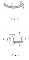
- restriction plate 5 ( Fig. 4 ) or restriction plates 5 ( Fig. 5 ) are preferably attached to one or both of opposite strain application surfaces 4 of the crosslinked elastomer body to promote the resistance increase occurring due to the bending strain.
- the restriction plate 5 is not particularly limited, but examples thereof include resin films such as of polyethylenes (PEs), polyethylene terephthalates (PETs) and polyimides (PIs), and metal plates such as vibration suppressing steel plates.
- resin films such as of polyethylenes (PEs), polyethylene terephthalates (PETs) and polyimides (PIs)
- metal plates such as vibration suppressing steel plates.
- the inventive crosslinked elastomer body serves as an electrical conductor (or a semiconductor) having a volume resistance of not greater than about 100 M ⁇ cm when neither compressive strain nor bending strain is applied to the elastomer body (under no strain), but serves as an insulator with an increased resistance under compressive strain or bending strain.
- the initial electrical conductivity (resistance) of the elastomer body can be controlled within a predetermined range by properly selecting the type and the amount of the electrically conductive filler to be added, and the range of the resistance change can be controlled from one order to five or more orders of magnitude. Therefore, a dynamic range can be selected to provide a resistance changeable sensor capability.
- parts 85 parts by weight (hereinafter referred to simply as "parts") (85 g) of an oil extension ethylene-propylene-diene terpolymer (EPDM)(ESPRENE 6101 available from Sumitomo Chemical Co., Ltd.), 34 parts (34g) of an oil extension EPDM (ESPRENE 601 available from Sumitomo Chemical Co., Ltd.), 30 parts (30g) of an EPDM (ESPRENE 505 available from Sumitomo Chemical Co., Ltd.), 5 parts (5 g) of zinc oxide (two types of zinc oxide available from Hakusui Tech Co., Ltd.), 1 part (1 g) of stearic acid (LUNAC S30 available from Kao Corporation) and 20 parts (20 g) of a paraffin process oil (SUNPAR 110 available from Nippon Sun Oil Company) were kneaded by a roll kneader.
- EPDM oil extension ethylene-propylene-diene terpolymer
- ESPRENE 601 available
- a spherical particulate carbon filler (NICABEADS ICB0520 available from Nippon Carbon Co., Ltd.) having an average particle diameter of 5 ⁇ m and a D90/D10 ratio of 3.2 in particle diameter frequency distribution was added, and mixed and dispersed in the resulting mixture by the roll kneader.
- NICABEADS ICB0520 available from Nippon Carbon Co., Ltd.
- an electrically conductive composition was prepared.
- the spherical particulate carbon filler (electrically conductive filler) was present in a volume fraction of about 48 vol% in the electrically conductive composition, and had a percolation critical volume fraction ( ⁇ c) of 43 vol% and a saturated volume fraction ( ⁇ s) of 48 vol%.
- the gel fraction was about 3% which was determined by dissolving the uncrosslinked electrically conductive composition in a good solvent (toluene) and measuring the amount of an insoluble portion of the composition.
- the electrically conductive composition was formed into an uncrosslinked rubber sheet having dimensions of 150 mm ⁇ 1500 mm ⁇ 2 mm (thickness).
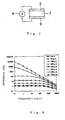
- the uncrosslinked rubber sheet was filled in a rectangular box-shaped mold having dimensions of 10 mm ⁇ 10 mm ⁇ 5 mm (height), and press-vulcanized at a temperature of 170°C for 30 minutes with a pair of copper plates (electrodes) 6 attached to vertically opposite end faces of the filled sheet.
- a sensor body 7 of a crosslinked EPDM (crosslinked product) with the electrodes 6 attached thereto was prepared as shown in Fig. 6 .
- the sensor body was evaluated by employing an impedance measuring apparatus 8 adapted to measure impedance in an electrical circuit based on an AC current and voltage.
- an impedance measuring apparatus 8 adapted to measure impedance in an electrical circuit based on an AC current and voltage.
- dielectric test electrodebars HP-16451B available fromHewlett-Packard Company
- an impedance analyzer HP-4194A available from Hewlett-Packard Company
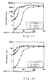
- Z-f impedance-frequency characteristics
- impedance observed at 0.1 kHz under no strain was about 1 k ⁇ , and increased with the strain.
- the impedance was about 10 M ⁇ (10 1 k ⁇ ).
- the impedance was increased to about 100 M ⁇ (10 5 k ⁇ ) or greater. That is, the crosslinked product was transformed from a conductor to an insulator with its resistance R changed from about 1 k ⁇ by 5 orders of magnitude by the application of the compressive strain.
- An electrically conductive composition was prepared in substantially the same manner as in Example 1, except that the spherical particulate carbon filler (NICABEADS ICB0520 available from Nippon Carbon Co., Ltd.) was blended in a proportion of 260 parts (260 g).
- the spherical particulate carbon filler (electrically conductive filler) was present in a volume fraction of about 47 vol% in the electrically conductive composition, and had a percolation critical volume fraction ( ⁇ c) of 43 vol% and a saturated volume fraction ( ⁇ s) of 48 vol%.
- the electrically conductive composition was formed into an uncrosslinked rubber sheet having dimensions of 150 mm ⁇ 1500 mm ⁇ 2 mm (thickness).
- the uncrosslinked rubber sheet was filled in a rectangular box-shaped mold having dimensions of 10 mm ⁇ 10 mm ⁇ 5 mm (height), and press-vulcanized at a temperature of 170°C for 30 minutes with a pair of copper plates (electrodes) 6 attached to vertically opposite end faces of the filled sheet.
- a sensor body 7 of a crosslinked EPDM (crosslinked product) with the electrodes 6 attached thereto was prepared as shown in Fig. 6 .
- impedance-frequency characteristics (Z-f) were determined with a thicknesswise compressive strain applied to the sensor body as shown in Fig. 7 .
- the results are shown in Fig. 9 .
- impedance observed at 0.1 kHz under no strain was about 200 k ⁇ , and increased with the strain.
- the impedance was about 3 M ⁇ (3000 k ⁇ ).
- the impedance was increased to 100 M ⁇ (10 5 k ⁇ ) or greater. That is, the crosslinked product was transformed from a semiconductor having a resistance R of about 200 k ⁇ to an insulator by the application of the compressive strain.
- An electrically conductive composition was prepared in substantially the same manner as in Example 1, except that the spherical particulate carbon filler (NICABEADS ICB0520 available from Nippon Carbon Co., Ltd.) was blended in a proportion of 240 parts (240 g).
- the spherical particulate carbon filler (electrically conductive filler) was present in a volume fraction of about 45 vol% in the electrically conductive composition, and had a percolation critical volume fraction ( ⁇ c) of 43 vol% and a saturated volume fraction ( ⁇ s) of 48 vol%.
- the electrically conductive composition was formed into an uncrosslinked rubber sheet having dimensions of 150 mm ⁇ 1500 mm ⁇ 2 mm (thickness).
- the uncrosslinked rubber sheet was filled in a rectangular box-shaped mold having dimensions of 10 mm ⁇ 10 mm ⁇ 5 mm (height), and press-vulcanized at a temperature of 170°C for 30 minutes with a pair of copper plates (electrodes) 6 attached to vertically opposite end faces of the filled sheet.
- a sensor body 7 of a crosslinked EPDM (crosslinked product) with the electrodes 6 attached thereto was prepared as shown in Fig. 6 .
- impedance-frequency characteristics (Z-f) were determined with a thicknesswise compressive strain applied to the sensor body as shown in Fig. 7 . The results are shown in Fig. 10 .
- impedance observed at 0.1 kHz under no strain was about 3 M ⁇ (3000 k ⁇ ), and increased with the strain.
- the impedance was about 10 M ⁇ .
- the impedance was increased to 100 M ⁇ (10 5 k ⁇ ) or greater. That is, the crosslinked product was transformed from a semiconductor having a resistance R of about 3 M ⁇ to an insulator by the application of the compressive strain.
- the results shown in Figs. 11 to 13 indicate that the initial electrical conductivity of each of the crosslinked products (the high conductor of Example 1, the intermediate conductor of Example 2 and the low conductor of Example 3) and the change rate of the electrical conductivity with respect to the static compressive strain are controllable by adjusting the amount of the spherical particulate carbon filler (electrically conductive filler).
- these crosslinked products are each made of a rubber material, so that the shape design flexibility is higher and the electrical conductivity change rate with respect to the strain is flexibly controllable. Therefore, these crosslinked products are advantageously employed as materials for strain detection sensors.
- a silicone rubber (KE931-U available from Shin-Etsu Chemical Co., Ltd) was kneaded by a roll kneader. Then, 78 parts (156 g) of a spherical particulate carbon filler (NICABEADS ICB0520 available from Nippon Carbon Co., Ltd.) was added, and mixed and dispersed in the silicone rubber by the roll kneader.
- NICABEADS ICB0520 available from Nippon Carbon Co., Ltd.
- spherical particulate carbon filler (electrically conductive filler) was present in a volume fraction of about 37 vol% in the resulting electrically conductive composition, and had a percolation critical volume fraction ( ⁇ c) of 34 vol% and a saturated volume fraction ( ⁇ s) of 50 vol%.
- the electrically conductive composition was formed into an uncrosslinked rubber sheet having dimensions of 150 mm ⁇ 1500 mm ⁇ 2 mm (thickness).
- the uncrosslinked rubber sheet was filled in a rectangular box-shaped mold having dimensions of 10 mm ⁇ 10 mm ⁇ 3 mm (height), and press-vulcanized at a temperature of 170°C for 30 minutes with a pair of copper plates (electrodes) 6 attached to vertically opposite end faces of the filled sheet.
- a sensor body 7 of a crosslinked silicone rubber (crosslinked product) with the electrodes 6 attached thereto was prepared as shown in Fig. 6 .
- impedance-frequency characteristics (Z-f) were determined with a thicknesswise compressive strain applied to the sensor body as shown in Fig. 7 .
- the results are shown in Fig. 14 .
- impedance observed at 0.1 kHz under no strain was about 1 k ⁇ , and increased with the strain.
- a compressive strain of 500 ⁇ m (17% strain) was applied to the sensor body, the impedance was about 100 k ⁇ .
- a compressive strain of 750 ⁇ m (25% strain) was applied to the sensor body, the impedance was about 2 M ⁇ (2000 k ⁇ ).
- the impedance was increased to 100 M ⁇ (10 5 k ⁇ ) or greater (not shown). That is, the crosslinked product was transformed from a conductor having a resistance R of about 1 k ⁇ to an insulator by the application of the compressive strain.
- the results shown in Fig. 15 indicate that the impedance changes according to the compressive strain in Example 4 .
- An electrically conductive composition was prepared in substantially the same manner as in Example 1, except that 175 parts (175 g) of a lower-structured general-purpose carbon black (ASAHI-THERMAL available from Asahi Carbon Co., Ltd. and having an average particle diameter of 0.08 ⁇ m) was employed instead of the spherical particulate carbon filler (NICABEADS ICB0520 available from Nippon Carbon Co., Ltd.)
- the lower-structured general-purpose carbon black (electrically conductive filler) was present in a volume fraction of about 32 vol% in the electrically conductive composition, and had a percolation critical volume fraction ( ⁇ c) of 32 vol% and a saturated volume fraction ( ⁇ s) of 50 vol%.
- the gel fraction was about 11% which was determined by dissolving the uncrosslinked electrically conductive composition in a good solvent (toluene) and measuring the amount of an insoluble portion of the composition.
- the electrically conductive composition was formed into an uncrosslinked rubber sheet having dimensions of 150 mm ⁇ 1500 mm ⁇ 2 mm (thickness).
- the uncrosslinked rubber sheet was filled in a rectangular box-shaped mold having dimensions of 10 mm ⁇ 10 mm ⁇ 3 mm (height), and press-vulcanized at a temperature of 170°C for 30 minutes with a pair of copper plates (electrodes) 6 attached to vertically opposite end faces of the filled sheet.
- a sensor body 7 of a crosslinked EPDM (crosslinked product) with the electrodes 6 attached thereto was prepared as shown in Fig. 6 .
- impedance-frequency characteristics (Z-f) were determined with a thicknesswise compressive strain applied to the sensor body as shown in Fig. 7 .
- the results are shown in Fig. 16 .
- impedance observed at 0.1 kHz under no strain was about 3 M ⁇ (3000 k ⁇ ).
- compressive stain was increased up to about 200 ⁇ m (7% strain)
- the impedance was reduced.
- the impedance was gradually increased.
- a compressive strain of 750 ⁇ m (25% strain) was applied to the sensor body
- the impedance was about 10 M ⁇ (10 4 k ⁇ ).
- the impedance was gradually increased to 100 M ⁇ (10 5 k ⁇ ) or greater (not shown).
- the crosslinked product was transformed from a semiconductor having a resistance R of about 3 M ⁇ to an insulator by the application of the compressive strain.
- the resistance was not monotonically increased according to the compressive strain, so that the crosslinked product may serve as a resistance increasing type rubber sensor only in a compressive strain range of not less than about 7% strain (not less than 200 ⁇ m).
- a rubber sensor of a resistance increasing type operative only in a resistance increasing range may be provided by employing an initial resistance value determined by preliminarily applying a compressive strain of about 200 ⁇ m (an offset of about 200 ⁇ m).
- each employing the spherical particulate carbon filler as the electrically conductive filler are more preferable as a sensor material than the crosslinked product of Example 5 employing the lower-structured general purpose carbon black as the electrically conductive filler, because the electrical conductivity monotonically changes with respect to the strain.
- the results shown in Fig. 17 indicate that the impedance changes according to the compressive strain in Example 5.
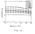
- An electrically conductive composition was prepared in substantially the same manner as in Example 1, except that the spherical particulate carbon filler (NICABEADS ICB0520 available from Nippon Carbon Co., Ltd.) was blended in a proportion of 100 parts (100 g) .
- the spherical particulate carbon filler (electrically conductive filler) was present in a volume fraction of about 26 vol% in the electrically conductive composition, and had a percolation critical volume fraction ( ⁇ c) of 43 vol% and a saturated volume fraction ( ⁇ s) of 48 vol%.
- the electrically conductive composition was formed into an uncrosslinked rubber sheet having dimensions of 150 mm ⁇ 1500 mm ⁇ 2 mm (thickness).
- the uncrosslinked rubber sheet was filled in a rectangular box-shaped mold having dimensions of 10 mm ⁇ 10 mm ⁇ 5 mm (height), and press-vulcanized at a temperature of 170°C for 30 minutes with a pair of copper plates (electrodes) 6 attached to vertically opposite end faces of the filled sheet.
- a sensor body 7 of a crosslinked EPDM (crosslinked product) with the electrodes 6 attached thereto was prepared as shown in Fig. 6 .
- impedance-frequency characteristics (Z-f) were determined with a thicknesswise compressive strain applied to the sensor body as shown in Fig. 7 .
- the results are shown in Fig. 18 .
- the crosslinked product of Comparative Example 1 was an insulator with no change in impedance responsive to application of strain. Therefore, it is difficult to employ the crosslinked product for sensing the strain.
- the HAF carbon black (electrically conductive filler) was present in a volume fraction of about 33 vol% in the electrically conductive composition, and had a percolation critical volume fraction ( ⁇ c) of 27 vol% and a saturated volume fraction ( ⁇ s) of 33 vol%.
- the electrically conductive composition was formed into an uncrosslinked rubber sheet having dimensions of 150 mm ⁇ 1500 mm ⁇ 2 mm (thickness).
- the uncrosslinked rubber sheet was filled in a rectangular box-shaped mold having dimensions of 10 mm ⁇ 10 mm ⁇ 3 mm (height), and press-vulcanized at a temperature of 150°C for 20 minutes with a pair of copper plates (electrodes) 6 attached to vertically opposite end faces of the filled sheet.
- a sensor body 7 of a crosslinked natural rubber with the electrodes 6 attached thereto was prepared as shown in Fig. 6 .
- impedance-frequency characteristics (Z-f) were determined with a thicknesswise compressive strain applied to the sensor body as shown in Fig. 7 .
- the results are shown in Fig. 19 .
- the crosslinked product was a high conductor, and its resistance was slightly reduced in response to the application of the strain (the electrical conductivity was improved by the compressive strain). However, a change in resistance was small, so that the crosslinked product was unacceptable for use as a resistance increasing type sensor material intended by the present invention.
- the inventive crosslinked elastomer body may be employed, for example, for an automotive seating state detection sensor, a bed surface pressure distribution sensor and a drawing tablet sensor which are based on detection of a surface pressure, and an automotive crash state detection sensor, a robot joint bending state detection sensor, a living body motion detection sensor (for motion capture and for detection of a breathing state, a muscle relaxing state and other living body motions) and a window glass breakage detection sensor which are based on detection of a bending state, and the like.
Landscapes
- Physics & Mathematics (AREA)
- Chemical & Material Sciences (AREA)
- Dispersion Chemistry (AREA)
- Spectroscopy & Molecular Physics (AREA)
- Compositions Of Macromolecular Compounds (AREA)
- Non-Insulated Conductors (AREA)
Claims (6)
- Corps réticulé en élastomère pour une sonde, qui se compose d'un mélange électriquement conducteur comportant un matériau de remplissage électriquement conducteur et un élastomère isolant en tant que composants essentiels,
où l'élastomère isolant est choisi parmi le groupe contenant les caoutchoucs de silicone, les caoutchoucs de copolymères d'éthylène-propylène, les caoutchoucs naturels, les caoutchoucs de copolymères de styrène-butadiène, les caoutchoucs de copolymères de butadiène d'acrylonitrile et les caoutchoucs acryliques,
où le matériau de remplissage électriquement conducteur inclut des matériaux de remplissage à base de carbone tels que des noirs de carbone et de matériaux de remplissage en forme de fines particules métalliques qui peuvent être employés seuls ou en association, sous la forme de particules sphériques, dans l'état le plus resserré quand le corps en élastomère n'est soumis à aucune contrainte, et avec un diamètre moyen de particules entre 0,05 et 100 µm,
où le matériau de remplissage électriquement conducteur présente une fraction volumique critique (φc) qui n'est pas inférieure à 30% en volume comme déterminé au premier point d'inflexion d'une courbe de percolation auquel une transition isolant-conducteur se produit avec une résistance électrique rapidement réduite quand le matériau de remplissage électriquement conducteur est graduellement ajouté à l'élastomère,
où le matériau de remplissage électriquement conducteur est présent à une fraction volumique qui n'est pas inférieure à la fraction volumique critique (φc) du mélange, et la fraction volumique du matériau de remplissage électriquement conducteur calculé comme [volume du matériau de remplissage électriquement conducteur]/[volume de mélange électriquement conducteur] x 100 est de 30 à 65 % en volume ;
et de sorte que la résistance du corps d'élastomère soumis à une contrainte compressive ou de flexion s'accroît lorsque comparée à la résistance du corps en élastomère observée en l'absence de contrainte
et le corps en élastomère sert de conducteur électrique ou de semi-conducteur ayant une résistance volumique non sensiblement supérieure à environ 100 MΩ·cm quand ni une contrainte compressive ni une contrainte de flexion ne sont appliquées au corps en élastomère mais se comporte comme un isolant avec une résistance accrue sous une contrainte compressive ou de flexion. - Corps réticulé en élastomère selon la revendication 1,
où le matériau de remplissage électriquement conducteur présente une fraction volumique saturée (φs) qui n'est pas inférieure à 35 % en volume comme déterminé à un deuxième point d'inflexion de la courbe de percolation correspondant à une modification de la résistance électrique qui est réduite pour être saturée même lors d'une addition complémentaire de matériau de remplissage électriquement conducteur, où le matériau de remplissage électriquement conducteur est présent dans une fraction volumique qui n'est pas inférieure à la fraction volumique saturée (φs) dans le mélange. - Corps réticulé en élastomère selon les revendications 1 ou 2,
où une fraction de gel comme calculée à partir de l'expression suivante (1) n'est pas supérieure à 15% en volume:
où Wg est le poids d'une partie insoluble du mélange électriquement conducteur obtenu en dissolvant le mélange électriquement conducteur dans un bon dissolvant pour l'élastomère avant la réticulation (le poids d'un gel composé d'un mélange électriquement conducteur avec un élastomère), et où Wf est le poids du matériau de remplissage électriquement conducteur. - Corps réticulé en élastomère selon l'une quelconque des revendications 1 à 3,
où le matériau de remplissage électriquement conducteur est du noir de charbon sphérique. - Corps réticulé en élastomère selon l'une quelconque des revendications 1 à 4, qui a des surfaces opposées d'application de contrainte, dont au moins l'une est équipée d'une forme de restriction.
- Méthode de production pour produire un corps réticulé en élastomère selon l'une quelconque des revendications 1à 5, qui comporte les étapes suivantes :fourniture d'un matériau de remplissage électriquement conducteur qui inclut des matériaux de remplissage en carbone tels que des noirs de carbone et de fines particules métalliques qui peuvent être employées seules ou en association, sous la forme de particules sphériques présentant un diamètre moyen compris entre 0,05 et 100 µm et d'un élastomère isolant qui est choisi dans le groupe les caoutchoucs de silicone, les caoutchoucs de copolymères de propylène d'éthylène, les caoutchoucs normaux, les caoutchoucs de copolymères de styrène-butadiène, les caoutchoucs de copolymères de butadiène d'acrylonitrile et les caoutchoucs acryliques ;préparation d'un mélange électriquement conducteur en mélangeant le matériau de remplissage électriquement conducteur et l'élastomère en tant que composants essentiels et un agent de vulcanisation comme composant facultatif, le matériau électriquement conducteur étant présent au moins à 30% en volume dans le mélange électriquement conducteur ;et dont la fraction volumique du matériau de remplissage électriquement conducteur calculée comme [volume du matériau de remplissage électriquement conducteur]/[volume du mélange électriquement conducteur] x 100 est compris entre 30 à 65 % en volume;et forment un mélange électriquement conducteur avec une forme prédéterminée, puis en réticulant le mélange et où les particules du matériau de remplissage électriquement conducteur sont dans l'état le plus resserré lorsque le corps en élastomère n'est sous aucune contrainte,et le corps en élastomère sert de conducteur électrique ou de semi-conducteur ayant une résistance volumique non supérieure à environ 100 MΩ·cm quand ni la contrainte compressive ni une contrainte de flexion ne sont appliquées au corps en élastomère, mais sert d'isolateur avec une résistance accrue sous une contrainte compressive ou de flexion.
Applications Claiming Priority (1)
| Application Number | Priority Date | Filing Date | Title |
|---|---|---|---|
| JP2006250938A JP5166714B2 (ja) | 2006-09-15 | 2006-09-15 | センサー用架橋エラストマー体およびその製法 |
Publications (2)
| Publication Number | Publication Date |
|---|---|
| EP1901311A1 EP1901311A1 (fr) | 2008-03-19 |
| EP1901311B1 true EP1901311B1 (fr) | 2011-11-09 |
Family
ID=38698237
Family Applications (1)
| Application Number | Title | Priority Date | Filing Date |
|---|---|---|---|
| EP07018009A Not-in-force EP1901311B1 (fr) | 2006-09-15 | 2007-09-13 | Corps en élastomère réticulé |
Country Status (3)
| Country | Link |
|---|---|
| US (1) | US7563393B2 (fr) |
| EP (1) | EP1901311B1 (fr) |
| JP (1) | JP5166714B2 (fr) |
Families Citing this family (21)
| Publication number | Priority date | Publication date | Assignee | Title |
|---|---|---|---|---|
| JP5496446B2 (ja) * | 2007-07-12 | 2014-05-21 | 東海ゴム工業株式会社 | 静電容量型センサ |
| US7958789B2 (en) * | 2008-08-08 | 2011-06-14 | Tokai Rubber Industries, Ltd. | Capacitive sensor |
| DE102009001930B4 (de) * | 2009-03-27 | 2018-01-04 | Robert Bosch Gmbh | Sensorbaustein |
| JP5622471B2 (ja) * | 2010-07-28 | 2014-11-12 | 住友理工株式会社 | 抵抗増加型センサおよびその製造方法 |
| CN102272566B (zh) * | 2009-11-24 | 2013-09-25 | 东海橡塑工业株式会社 | 弯曲传感器及变形形状测量方法 |
| JP5654789B2 (ja) * | 2009-11-24 | 2015-01-14 | 住友理工株式会社 | 曲げセンサおよび変形形状測定方法 |
| WO2011118315A1 (fr) | 2010-03-23 | 2011-09-29 | 東海ゴム工業株式会社 | Produit électroconducteur réticulé, procédé de production dudit produit, et capteur, carte à circuit flexible et écran à ondes électromagnétiques fabriqués en utilisant ledit produit |
| JP5486683B2 (ja) * | 2010-11-04 | 2014-05-07 | 東海ゴム工業株式会社 | 曲げセンサ |
| WO2013122740A1 (fr) * | 2012-02-17 | 2013-08-22 | Tyco Electronics Corporation | Ensemble contact pour connecteur électrique |
| JP5876358B2 (ja) | 2012-03-30 | 2016-03-02 | 国立大学法人九州大学 | 歩行運動補助具 |
| JP5986445B2 (ja) | 2012-07-20 | 2016-09-06 | 国立大学法人九州大学 | 歩行用遊脚振子運動補助具およびアシスト力の制御方法 |
| EP2829857A1 (fr) * | 2013-07-24 | 2015-01-28 | Ecole Polytechnique | Matériau piézorésistif présentant un facteur de jauge optimal |
| WO2015172897A1 (fr) * | 2014-05-12 | 2015-11-19 | Koninklijke Philips N.V. | Capteur en composite de silicone pour le mesure de la frequence cardiaque |
| EP2957225A1 (fr) * | 2014-06-18 | 2015-12-23 | STBL Medical Research AG | Dispositif de jauge de contrainte et équipement avec de tels dispositifs |
| WO2016108996A1 (fr) * | 2014-10-17 | 2016-07-07 | The University Of Florida Research Foundation, Inc. | Procédés et structures pour revêtements de régulation de la lumière |
| ITTO20150046U1 (it) * | 2015-04-10 | 2016-10-10 | Guido Maisto | Dispositivo per la rilevazione di deformazioni e la trasmissione dei dati rilevati |
| DE102015223238A1 (de) | 2015-11-24 | 2017-05-24 | Sgl Carbon Se | Kunststoff-Bauteil mit Kohlenstofffüllstoff |
| CN108151640B (zh) * | 2018-01-17 | 2024-04-16 | 中国科学院宁波材料技术与工程研究所 | 弹性导体在测量尺中的应用、电子测量尺及测量方法 |
| DE102019110264A1 (de) | 2019-04-18 | 2020-10-22 | Uvex Safety Gloves Gmbh & Co. Kg | Elektrischer polymerer Drucksensor |
| DE102019132028B3 (de) * | 2019-11-26 | 2021-04-15 | Deutsche Institute Für Textil- Und Faserforschung Denkendorf | Piezoresistiver Kraftsensor |
| US12466952B2 (en) * | 2020-06-25 | 2025-11-11 | Elkem Silicones France Sas | Thermally conductive silicone compositions |
Family Cites Families (17)
| Publication number | Priority date | Publication date | Assignee | Title |
|---|---|---|---|---|
| US4076652A (en) * | 1976-05-24 | 1978-02-28 | E. I. Du Pont De Nemours And Company | Elastic resistor compositions containing metallic-conductive particles and conductive lubricant particles |
| US5178797A (en) * | 1980-04-21 | 1993-01-12 | Raychem Corporation | Conductive polymer compositions having improved properties under electrical stress |
| US4806430A (en) * | 1985-12-03 | 1989-02-21 | Becton, Dickinson And Company | Film-forming silicone compositions having lubricating properties |
| JPH0635546B2 (ja) * | 1986-08-26 | 1994-05-11 | 信越化学工業株式会社 | 離型フィルム用シリコ−ン組成物 |
| JPH0779006B2 (ja) * | 1989-09-04 | 1995-08-23 | イナバゴム株式会社 | 感圧導電性エラストマー |
| JPH03122911A (ja) * | 1989-10-04 | 1991-05-24 | Osaka Gas Co Ltd | 感圧導電性樹脂組成物 |
| US5476612A (en) * | 1989-12-30 | 1995-12-19 | Zipperling Kessler & Co., (Gmbh & Co.). | Process for making antistatic or electrically conductive polymer compositions |
| US5672297A (en) * | 1995-10-27 | 1997-09-30 | The Dow Chemical Company | Conductive composite articles based on expandable and contractible particulate matrices |
| US20030129384A1 (en) * | 2001-07-10 | 2003-07-10 | Kalchbrenner Joseph Carl | Printing blanket face and compressible layer compositions |
| US6500597B1 (en) * | 2001-08-06 | 2002-12-31 | Xerox Corporation | Toner coagulant processes |
| US7332227B2 (en) * | 2003-03-14 | 2008-02-19 | Becton, Dickinson And Company | Non-volatile lubricant system for medical devices |
| US20050187325A1 (en) * | 2004-02-20 | 2005-08-25 | Yuan Hui L. | Silicone gasket compositions |
| US20050187324A1 (en) * | 2004-02-20 | 2005-08-25 | Yuan Hui L. | Silicone gasket compositions |
| KR100579836B1 (ko) * | 2004-06-04 | 2006-05-15 | 삼성전자주식회사 | 미세 입자경 토너 제조 방법 |
| US20050282000A1 (en) * | 2004-06-16 | 2005-12-22 | General Electric Company | Multilayer composites with special visual effects |
| DE102004032152A1 (de) * | 2004-07-02 | 2006-01-26 | Ticona Gmbh | Verbund umfassend mindestens eine harte Komponente und mindestens eine weiche Komponente |
| JP5568206B2 (ja) * | 2006-09-15 | 2014-08-06 | 東海ゴム工業株式会社 | 変形センサ |
-
2006
- 2006-09-15 JP JP2006250938A patent/JP5166714B2/ja not_active Expired - Fee Related
-
2007
- 2007-09-13 EP EP07018009A patent/EP1901311B1/fr not_active Not-in-force
- 2007-09-14 US US11/855,601 patent/US7563393B2/en not_active Expired - Fee Related
Also Published As
| Publication number | Publication date |
|---|---|
| JP2008069313A (ja) | 2008-03-27 |
| EP1901311A1 (fr) | 2008-03-19 |
| US20080067477A1 (en) | 2008-03-20 |
| JP5166714B2 (ja) | 2013-03-21 |
| US7563393B2 (en) | 2009-07-21 |
Similar Documents
| Publication | Publication Date | Title |
|---|---|---|
| EP1901311B1 (fr) | Corps en élastomère réticulé | |
| US7703333B2 (en) | Deformation sensor | |
| EP2015043B1 (fr) | Capteur à capacité électrostatique | |
| Dong et al. | Resistive and capacitive strain sensors based on customized compliant electrode: Comparison and their wearable applications | |
| US8511174B2 (en) | Strain sensor and corresponding sensor arrangement | |
| EP2905574B1 (fr) | Feuille de capteur de type capacitif, son procédé de fabrication et capteur | |
| JP4368392B2 (ja) | 変形センサシステム | |
| Costa et al. | Mechanical vs. electrical hysteresis of carbon nanotube/styrene–butadiene–styrene composites and their influence in the electromechanical response | |
| JP2008239746A (ja) | エラストマー複合材料 | |
| Sánchez et al. | Enhancing sensing performance of 3D-printed TPU/CB piezoresistive strain sensors through integration of silver ink IDE | |
| Banks et al. | Direct ink writing of piezoresistive isoprene rubber nanocomposites | |
| JP2008197060A (ja) | 変形センサシステム | |
| JP5578728B2 (ja) | 外力検出が可能な防振装置 | |
| JP2009139329A (ja) | センサ用エラストマー複合材料および変形センサ | |
| JP2006208052A (ja) | ゴム物品用歪センサー | |
| JP5085298B2 (ja) | 導電複合粒子、エラストマー複合材料、および変形センサ | |
| Promsung et al. | Piezoresistive Natural Rubber Composites: a Comparison between Low‐Temperature Glutaraldehyde Curing Agents and Conventional Sulfur Curing Systems | |
| Huang et al. | Two types of flexible tactile sensor arrays of robot for three-dimension force based on piezoresistive effects | |
| JP2011226852A (ja) | 感圧センサの製造方法、感圧センサ、および弾性組成物 | |
| JP5980993B1 (ja) | 感圧センサ | |
| Bhagavatheswaran | Exploring the Piezoresistive Characteristics of Solution Styrene Butadiene Rubber composites under static and Dynamic Conditions-A Novel Route to Visualize Filler Network Behavior in Rubbers | |
| JP2015200501A (ja) | 歪み計測装置、歪み量及び歪み方向計測方法 | |
| JP2008241528A (ja) | 変形センサシステム | |
| JP2008286747A (ja) | 変形センサシステム | |
| JP2006337118A (ja) | エラストマセンサと該エラストマセンサを用いた振動検出方法。 |
Legal Events
| Date | Code | Title | Description |
|---|---|---|---|
| PUAI | Public reference made under article 153(3) epc to a published international application that has entered the european phase |
Free format text: ORIGINAL CODE: 0009012 |
|
| AK | Designated contracting states |
Kind code of ref document: A1 Designated state(s): AT BE BG CH CY CZ DE DK EE ES FI FR GB GR HU IE IS IT LI LT LU LV MC MT NL PL PT RO SE SI SK TR |
|
| AX | Request for extension of the european patent |
Extension state: AL BA HR MK YU |
|
| 17P | Request for examination filed |
Effective date: 20080918 |
|
| AKX | Designation fees paid |
Designated state(s): DE FR GB |
|
| 17Q | First examination report despatched |
Effective date: 20100623 |
|
| GRAP | Despatch of communication of intention to grant a patent |
Free format text: ORIGINAL CODE: EPIDOSNIGR1 |
|
| GRAC | Information related to communication of intention to grant a patent modified |
Free format text: ORIGINAL CODE: EPIDOSCIGR1 |
|
| GRAS | Grant fee paid |
Free format text: ORIGINAL CODE: EPIDOSNIGR3 |
|
| GRAA | (expected) grant |
Free format text: ORIGINAL CODE: 0009210 |
|
| AK | Designated contracting states |
Kind code of ref document: B1 Designated state(s): DE FR GB |
|
| REG | Reference to a national code |
Ref country code: GB Ref legal event code: FG4D |
|
| REG | Reference to a national code |
Ref country code: DE Ref legal event code: R096 Ref document number: 602007018550 Country of ref document: DE Effective date: 20120209 |
|
| PLBE | No opposition filed within time limit |
Free format text: ORIGINAL CODE: 0009261 |
|
| STAA | Information on the status of an ep patent application or granted ep patent |
Free format text: STATUS: NO OPPOSITION FILED WITHIN TIME LIMIT |
|
| 26N | No opposition filed |
Effective date: 20120810 |
|
| REG | Reference to a national code |
Ref country code: DE Ref legal event code: R097 Ref document number: 602007018550 Country of ref document: DE Effective date: 20120810 |
|
| REG | Reference to a national code |
Ref country code: DE Ref legal event code: R084 Ref document number: 602007018550 Country of ref document: DE Effective date: 20130219 |
|
| GBPC | Gb: european patent ceased through non-payment of renewal fee |
Effective date: 20120913 |
|
| REG | Reference to a national code |
Ref country code: FR Ref legal event code: ST Effective date: 20130531 |
|
| PG25 | Lapsed in a contracting state [announced via postgrant information from national office to epo] |
Ref country code: GB Free format text: LAPSE BECAUSE OF NON-PAYMENT OF DUE FEES Effective date: 20120913 |
|
| PG25 | Lapsed in a contracting state [announced via postgrant information from national office to epo] |
Ref country code: FR Free format text: LAPSE BECAUSE OF NON-PAYMENT OF DUE FEES Effective date: 20121001 |
|
| REG | Reference to a national code |
Ref country code: DE Ref legal event code: R082 Ref document number: 602007018550 Country of ref document: DE Representative=s name: KUHNEN & WACKER PATENT- UND RECHTSANWALTSBUERO, DE |
|
| REG | Reference to a national code |
Ref country code: DE Ref legal event code: R082 Ref document number: 602007018550 Country of ref document: DE Representative=s name: KUHNEN & WACKER PATENT- UND RECHTSANWALTSBUERO, DE Effective date: 20141017 Ref country code: DE Ref legal event code: R081 Ref document number: 602007018550 Country of ref document: DE Owner name: SUMITOMO RIKO COMPANY LIMITED, KOMAKI-SHI, JP Free format text: FORMER OWNER: TOKAI RUBBER INDUSTRIES, LTD., KOMAKI-SHI, AICHI-KEN, JP Effective date: 20141017 |
|
| PGFP | Annual fee paid to national office [announced via postgrant information from national office to epo] |
Ref country code: DE Payment date: 20160907 Year of fee payment: 10 |
|
| REG | Reference to a national code |
Ref country code: DE Ref legal event code: R119 Ref document number: 602007018550 Country of ref document: DE |
|
| PG25 | Lapsed in a contracting state [announced via postgrant information from national office to epo] |
Ref country code: DE Free format text: LAPSE BECAUSE OF NON-PAYMENT OF DUE FEES Effective date: 20180404 |