EP2015043B1 - Capteur à capacité électrostatique - Google Patents
Capteur à capacité électrostatique Download PDFInfo
- Publication number
- EP2015043B1 EP2015043B1 EP08009644A EP08009644A EP2015043B1 EP 2015043 B1 EP2015043 B1 EP 2015043B1 EP 08009644 A EP08009644 A EP 08009644A EP 08009644 A EP08009644 A EP 08009644A EP 2015043 B1 EP2015043 B1 EP 2015043B1
- Authority
- EP
- European Patent Office
- Prior art keywords
- electrostatic capacity
- electrodes
- deformation
- type sensor
- pair
- Prior art date
- Legal status (The legal status is an assumption and is not a legal conclusion. Google has not performed a legal analysis and makes no representation as to the accuracy of the status listed.)
- Active
Links
Images









Classifications
-
- G—PHYSICS
- G01—MEASURING; TESTING
- G01L—MEASURING FORCE, STRESS, TORQUE, WORK, MECHANICAL POWER, MECHANICAL EFFICIENCY, OR FLUID PRESSURE
- G01L1/00—Measuring force or stress, in general
- G01L1/14—Measuring force or stress, in general by measuring variations in capacitance or inductance of electrical elements, e.g. by measuring variations of frequency of electrical oscillators
- G01L1/142—Measuring force or stress, in general by measuring variations in capacitance or inductance of electrical elements, e.g. by measuring variations of frequency of electrical oscillators using capacitors
Definitions
- the present invention relates to an electrostatic capacity-type sensor for detecting a deformation based on a change in the electrostatic capacity between a pair of electrodes.
- an electrostatic capacity-type sensor utilizing a change in electrostatic capacity associated with a change in distance between a pair of electrodes, a compressive deformation can be detected.
- Japanese Unexamined Patent Publication (KOKAI) No. 5-288619 discloses an electrostatic capacity-type tactile sensor including a pair of metal electrodes facing each other across a space.
- Japanese Unexamined Patent Publication (KOKAI) No. 2005-315831 discloses an electrostatic capacity-type pressure sensor in which electrodes made of conductive cloth are arranged on both the surface of a sheet-shaped dielectric.
- the electrostatic capacity-type sensor disclosed in Japanese Unexamined Patent Publication (KOKAI) No. 5-288619 , a high dimensional accuracy is required in the distance between the electrodes, so that the manufacturing cost is high. Further, a metal material is used in the electrodes.. The metal electrodes have little expansion/contraction properties, so that, for example, when the electrode is bent, the electrode is easy to be broken due to plastic deformation. Also, when the electrostatic capacity-type sensor is formed by placing an elastically deformable dielectric between the metal electrodes, the dielectric can be deformed by bending, but the electrodes cannot follow the deformation of the dielectric. Hence, the electrode and the dielectric are separated from each other, so that the use of them cannot be repeated. In such a way, the electrostatic capacity-type sensor including the metal electrodes is not suitable to detect the bending deformation. Further, the sensor is difficult to be attached to a curved shape.
- the electrostatic capacity-type sensor disclosed in Japanese Unexamined Patent Publication (KOKAI) No. 2005-315831 uses an electrically-conductive cloth (conductive cloth) for the electrodes.
- the conductive cloth has expansion/contraction properties.
- the expansion/contraction direction is restricted by weaving method.
- the conductive cloth has a stitch, so that the area of the electrode becomes small by the clearance of the stitch to cause the electrostatic capacity to become small.
- US 3,814,998 discloses a pressure sensitive capacitance sensing unit including a diaphragm 3 (refer to Figs. 2 and 3 ).
- the diaphragm 3 is constructed a core 7 and electrodes 8, 9.
- the core 7 is formed of a dielectric material.
- the electrodes 8, 9 are formed of a conductive material.
- the conductive material has a matrix which is similar to the dielectric material of the core 7 and conductive particles 11, such as graphitized carbon, dispersed in the matrix.
- the electrodes 8, 9 are firmly attached in abutting relation to the opposite faces of the core 7.
- the present invention has been developed in view of such circumstances, and it is an object of the invention to provide an electrostatic capacity-type sensor which has an excellent durability and can detect a bending-deformation.
- An electrostatic capacity-type sensor of the present invention includes a dielectric film made of an elastomer and a pair of electrodes arranged via said dielectric film, and detects a deformation based on a change in the electrostatic capacity between said pair of electrodes, wherein said pair of electrodes consist of an elastomer composition including an elastomer and a conductive filler that is blended in said elastomer and is made of carbon material, in a percolation curve indicating a relationship between a blending amount of said conductive filler and an electric resistance of said elastomer composition, the blending amount (critical volume fraction: ⁇ c) of said conductive filler at a first flexure point, at which electric resistance lowers to cause a transition between insulator and conductor, is 25 vol% or less, Young's modulus of said pair of electrodes is 0.1 MPa or more and 10 MPa or less, and said pair of electrodes are expansible/contractible depending on the deformation of said dielectric film, and exhibit
- C capacitance
- ⁇ o dielectric constant in vacuum
- ⁇ r specific dielectric constant of dielectric
- S electrode area
- d distance between electrodes.
- a dielectric film made of elastomer is arranged between a pair of electrodes.
- the specific dielectric constant of the elastomer is larger than that of air.
- ⁇ r becomes large.
- the capacitance (C) becomes larger compared to that of the sensor including a pair of electrodes simply facing each other across a space, thereby allowing the detecting sensibility to be improved.
- a pair of electrodes use an elastomer as a base material. Hence, they are flexible and thus can be deformed integrally with the dielectric film. In other words, they, even when deformed by bending, can be deformed following to the deformation of the dielectric film.
- the term "deformation" in this specification includes all of the deformations due to compression, expansion/contraction, bending and the like. In such a way, a pair of electrodes are expansible/contractible depending to the deformation of the dielectric film, so that they can also be easily attached to a curved shape. Further, even when used repeatedly, the electrode and the dielectric film are difficult to be separated from each other, so that they are excellent in durability.
- a pair of electrodes use an elastomer as a base material, so that unlike the electrodes made of cloth, they are thick. In addition, they have good conductive properties and change a little in the conductive properties even when expanded/contracted, as a result of forming a conducting path by the conductive filler later described. Therefore, the function as electrodes is difficult to be degraded even when the deformation amount of the dielectric film is large.
- both the dielectric film and electrodes are formed of an elastomer, so that they are flexible as a whole of the sensor, and excellent in processability to cause a high degree of freedom in shape design.
- the electrostatic capacity-type sensor of the present invention can be widely used as a soft sensor. Further, the sensor is flexible, so that it can accommodate for even a case where the deformation amount is large, thereby providing a large detection range.
- the electrostatic capacity-type sensor of the present invention when an elastomer is arranged between the electrodes, the elastomer expands at a high temperature, so that the distance between the electrodes becomes larger. Hence, the capacitance becomes smaller by that extended distance fraction. In such a way, the capacitance changes at a high temperature due to factors other than deformation, so that deformation is difficult to be precisely detected.
- the electrostatic capacity-type sensor of the present invention the deformation can be precisely detected by correcting the change in film thickness due to temperature.
- the impedance decreases with the increase of temperature in the low-frequency range.
- a direct current resistance (R) component affects more largely the impedance than a capacitance (C) component.
- R decreases with the increase of temperature to cause the impedance to be decreased.
- a conductive filler when a conductive filler is mixed in an elastomer having insulation properties to form an elastomer composition, the electric resistance of the elastomer composition changes depending on a blended amount of the conductive filler.
- Fig. 1 shows typically the relationship between the blended amount of the conductive filler and the electric resistance in the elastomer composition.
- a conductive filler 102 As shown in Fig. 1 , as a conductive filler 102 is mixed in an elastomer 101, at first the electric resistance of the elastomer composition is hardly different from that of the elastomer 101. However, when the amount of the conductive filler 102 reaches a volume fraction, the electric resistance rapidly drops, thereby causing insulator-conductor transition (a first flexure point). The amount of the conductive filler 102 at the first flexure point is called a critical volume fraction ( ⁇ c). Also, as the conductive filler 102 is further mixed, a change in electric resistance becomes smaller from a point of a certain volume fraction to cause the change in electric resistance to be saturated (a second flexure point).
- the amount of the conductive filler 102 at the second flexure point is called a saturated volume fraction ( ⁇ S).
- ⁇ S saturated volume fraction
- Such a change in electric resistance is called a percolation curve, which is considered to be due to a fact that a conducting path P1 by the conductive filler 102 is formed in the elastomer 101.
- the conducting path is easy to be formed by a three-dimensional network structure.
- the critical volume fraction ( ⁇ c) of the elastomer composition becomes a relatively as small as about 20 vol%.
- the critical volume fraction ( ⁇ c) is small, the conductive filler is easy to form a secondary aggregate having structure properties.
- an elastomer composition having high electrical conductivity can be obtained.
- a pair of electrodes consist of an elastomer composition whose critical volume fraction ( ⁇ C) is 25 vol% or less. Since the critical volume fraction ( ⁇ C) is relatively small, the conductive filler is easy to form an aggregate. Thus, with a relatively small amount of conductive filler, electrodes having good electrical conductivity can be obtained.
- the elastomer composition in this specification includes a mixture of elastomer and conductive filler, as well as a mixture of elastomer, conductive filler, other additives and the like.
- the conductive filler is formed of carbon material.
- the carbon material has good electrical conductivity, and it is relatively inexpensive. Hence, using the conductive filler formed of carbon material allows a cost required for manufacturing an electrostatic capacity-type sensor to be reduced.
- the elastomer as a material of the dielectric film includes one or more compounds selected from the group consisting of silicone rubber, acrylonitrile-butadien copolymer rubber, acrylic rubber, epichlorohydrin rubber, chlorosulfonated polyethylene, chlorinated polyethylene, and urethane rubber.
- silicone rubber acrylonitrile-butadien copolymer rubber
- acrylic rubber epichlorohydrin rubber
- chlorosulfonated polyethylene chlorinated polyethylene
- urethane rubber urethane rubber
- the elastomer as a material of the pair of electrodes includes one or more compounds selected from the group consisting of silicone rubber, ethylene-propylene, copolymer rubber, natural rubber, styrene-butadien copolymer rubber, acrylonitrile-butadien copolymer rubber, acrylic rubber, epichlorohydrin rubber, chlorosulfonated polyethylene, chlorinated polyethylene, and urethane rubber.
- silicone rubber ethylene-propylene
- copolymer rubber natural rubber
- styrene-butadien copolymer rubber acrylonitrile-butadien copolymer rubber
- acrylic rubber epichlorohydrin rubber
- chlorosulfonated polyethylene chlorinated polyethylene
- urethane rubber urethane rubber
- a restraint member for restraining an elastic deformation of a surface of at least one of the pair of electrodes, which is elastically bending-deformable, is arranged on the surface.
- the elastic deformation of at least one of the surfaces of electrode due to bending-deformation is restricted by the restraint member. This causes a change in the distance between electrodes during bending-deformation to become large. Hence, the bending-deformation is more easily detected.
- the restraint member for restraining an elastic deformation of a surface of one of the pair of electrodes is arranged on the surface, and during bending-deformation, the direction of the bending-deformation can be discriminated based on a change in the electrostatic capacity between the pair of electrodes.
- the bending direction when the bending direction becomes reverse with respect to right and left, the changing behavior of the capacitance becomes reverse with respect to the deflection during bending-deformation.
- the bending direction can be discriminated based on the changing behavior of the capacitance.
- a pair of sensor elements including the dielectric film and the pair of electrodes are arranged on both respective sides of a plate-shaped, elastically bending-deformable reference member, and utilizing a fact that the increase/decrease of the film thickness of the dielectric film on both the sides of the reference member becomes reverse during bending-deformation, the bending-deformation is detected based on a difference between an electrostatic capacity change in one of the sensor elements and an electrostatic capacity change in the other of the sensor elements.
- the reference member plays a role in restraining the elastic deformation of the surface of adjacent electrodes.
- a compressive or tensile stress is applied to the respective dielectric films arranged on both the sides of the reference member. This causes the increase/decrease of the film thickness of the dielectric film, that is, the increase/decrease of the distance between electrodes with respect to bending-deformation becomes reverse on both the sides of the reference member.
- the electrostatic capacity change in individual sensor elements is small, the bending-deformation is detected based on a difference between an electrostatic capacity change in one of the sensor elements and an electrostatic capacity change in the other of the sensor elements, thereby allowing the detection sensibility to be improved.
- an electrostatic capacity-type sensor which has a high sensibility and provides little malfunction and erroneous discrimination.
- restraint members for restraining an elastic deformation of respective surfaces of the sensor elements are further arranged on the surfaces.
- the elastic deformation of respective surfaces of the sensor elements due to bending-deformation is restricted by the restraint member. This causes a change in the distance between electrodes to become large during bending-deformation. Hence, the bending-deformation is more easily detected.
- the electrostatic capacity-type sensor of the present invention comprises a dielectric film made of an elastomer and a pair of electrodes arranged via the dielectric film.
- the elastomer forming the dielectric film can be selected as required from rubber and thermoplastic elastomers.
- the elastomer which is not particularly limited, is desirable to have a high specific dielectric constant. More specifically, the specific dielectric constant at a room temperature is desirably 3 or more, more desirably 5 or more.
- an elastomer having a polar functional group for example, such as an ester group, a calboxyl group, a hydroxyl group, a halogen group, an amide group, a sulfone group, an urethane group, and a nitrile group, or an elastomer into which a polar low-molecular weight compound having one of these polar functional groups is added.
- the elastomer may be crosslinked or not crosslinked.
- Suitable elastomers include, for example, such as silicone rubber, acrylonitrile-butadien copolymer rubber, acrylic rubber, epichlorohydrin rubber, chlorosulfonated polyethylene, chlorinated polyethylene, and urethane rubber.
- the film thickness of a dielectric film which is not particularly limited, is desirable to be 1 ⁇ m or more and 3000 ⁇ m or less, in view of achieving a smaller size of the sensor, and of improving a detection sensibility by increasing the capacitance proportional to the inverse number of the film thickness. It is more suitable to be 50 ⁇ m or more and 500 ⁇ m or less.
- a pair of electrodes are arranged, across the above-mentioned dielectric film, on the respective surfaces of the dielectric film.
- the elastomer forming the electrodes may be the same as the one used for the dielectric film, or be different from it.
- the follow-up ability of the electrodes to the deformation of the dielectric film is improved.
- the adhesive properties of the dielectric film to the electrodes are also improved, so that even when subject to a repeated fatigue, the separation of the dielectric film from the electrodes is restrained to improve the reliability.
- the elastomer for electrodes is prepared to produce a mixture (elastomer composition) with the conductive filler
- the elastomer for electrodes is desirable to use the elastomer composition whose critical volume fraction ( ⁇ C) in the percolation curve is 25 vol% or less.
- the critical volume fraction ( ⁇ C) is 25 vol% or less, even if the amount of the conductive filler is relatively small, the electrodes having high electrical conductivity can be obtained.
- Elastomers suitable for electrodes include silicone rubber, ethylene-propylene copolymer rubber, natural rubber, styrene-butadien copolymer rubber, acrylonitrile-butadien copolymer rubber, acrylic rubber, epichlorohydrin rubber, chlorosulfonated polyethylene, chlorinated polyethylene, and urethane rubber and the like.
- the conductive filler blended in the elastomer is particles having electrically-conductive properties, and uses fine particles of carbon material or metal. It is sufficient to use one kind individually of these kinds of particles or use two or more kinds thereof by being mixed. For example, it is desirable to use carbon material because it is relatively cheap and easy to form a conductive path.
- carbon material for example, carbon black such as ketjen black is suitable because it has small particle size and excellent electrical conductivity.
- the shape of the conductive filler is not particularly limited to spherical, needle-like, prismatic and the like.
- the aspect ratio (ratio of long side to short side) of the conductive filler is desirable to be 1 or more.
- using a needle-like conductive filler having a relatively large aspect ratio allows a three-dimensional conductive network to be easily made, whereby with a small amount thereof, high electrical conductivity can be realized.
- a change in electrically-conductive properties during the expansion/contraction of the electrodes can be restrained.
- the average particle diameter (primary particle) of the conductive filler is desirable to be 0.01 ⁇ m or more and 0.5 ⁇ m or less.
- the diameter is less than 0.01 ⁇ m, the cohesiveness is high, the particle is difficult to be evenly dispersed when a coating material is prepared.
- it is 0.03 ⁇ m or more.
- the aggregate (secondary particle) is hardly to be formed.
- it is 0.1 ⁇ m or less.
- the conductive filler is desirable to be blended at a ratio of the critical volume fraction ( ⁇ c) in the percolation curve or more.
- ⁇ c critical volume fraction
- the packing rate of the conductive filler is desirable to be 25 vol% or less assuming that the volume of the electrode is 100 vol%. The packing rate of 15 vol% or less is more suitable.
- the packing rate of the conductive filler exceeds 30 vol%, a mixing with the elastomer becomes difficult to cause the molding processability to be reduced.
- the expansion/contraction properties of the electrodes is reduced. Hence, it is desirable to be 30 vol% or less.
- the film thickness of the electrodes which is not particularly limited, is desirable to be 1 ⁇ m or more and 100 ⁇ m or less, in view of considering of a follow-up ability to the dielectric film, and of achieving a smaller size of the sensor. Further, in order to improve the follow-up ability to the deformation of the dielectric film, the Young's modulus is desirable to be 0.1 MPa or more and 10 MPa or less. Similarly, the elongation at breaking in the tensile test (JIS K6251) is desirable to be 200% or more.
- the electrical resistance of the electrodes in the thickness direction and the surface direction is desirable to be 100 k ⁇ or less, and more suitable to be 10 k ⁇ or less.
- the electrode even when expanded/contracted, is small in the change of electrically-conductive properties. For example, when the electrode is extended in one direction to extend the distance between terminals by 100%, if the resistance across terminals (R1) is 10 or less times the resistance across terminals before extension (R0) (R1/R0 ⁇ 10), it can be said that "even when expanded/contracted, the change of electrically-conductive properties is small.”
- additives include, for example, crosslinking agent, vulcanization accelerator, processing aid, aging preventive agent, plasticizer, softening agent, coloring agent, and the like.
- a restraint member for restraining an elastic deformation of a surface of at least one of a pair of electrodes, on that surface.
- the restraint member which has insulation properties, and is elastically deformable, is not particularly limited.
- resin films such as polyimide (PI), polyethylene (PE), polyethylene terephthalate (PET), and the like.
- the electrostatic capacity-type sensor of the present invention may be formed by forming sensor elements of the above-mentioned dielectric film and the above-mentioned pair of electrodes, and arranging the sensor elements on both respective sides of a plate-shaped, elastically bending-deformable reference member.
- the reference member which has insulation properties, and is elastically deformable, is not particularly limited.
- resin films or resin plate such as polyimide (PI), polyethylene (PE), polyethylene terephthalate (PET), and the like.
- PI polyimide
- PE polyethylene
- PET polyethylene terephthalate
- the restraint member is described as above.
- the electrostatic capacity-type sensor of the present invention can be manufactured, for example, in the following manner.
- an additive such as processing aid and vulcanization accelerator is added to the elastomer for the dielectric film to be kneaded so as to form an elastomer composition.
- the elastomer composition is molded into sheet form, and the composition thus molded is packed into a mold, in which the composition is crosslinked under predetermined conditions to prepare a dielectric film.
- an elastomer for electrodes, a conductive filler and an additive such as vulcanization accelerator are dispersed and mixed in a solvent to form a coating material, and then, the coating material is molded into thin-film form to prepare an unvulcanized electrode.
- the unvulcanized electrode is arranged on the pair of surfaces of the prepared dielectric film, and both the electrode and the dielectric film are pressed under predetermined conditions for vulcanization and adhering.
- the dielectric film and the electrode may adhere to each other only by mutual adhesive power (tack).
- tack mutual adhesive power
- the adhesion of both the materials is improved, thereby further improving the durability.
- the reference member and the restraint member are arranged, it is sufficient that they are allowed to adhere to the electrode surface by an adhesive and the like.
- embodiments of the electrostatic capacity-type sensor of the present invention are not limited to the present embodiments.
- the embodiments can be embodied with various modified aspects and improved aspects that the person skilled in the art can perform.
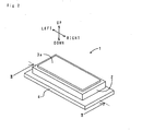
- an electrostatic capacity-type sensor 1 comprises a dielectric film 2, a pair of electrodes 3a, 3b, and a restraint member 4.
- the dielectric film 2 is made of acrylic rubber, and assumes a band shape extending horizontally.
- a film thickness d of the dielectric film 2 is about 200 ⁇ m.
- the dielectric film 2 is arranged via the electrode 3b on the upper side of the restraint member 4 later described.
- the pair of electrodes 3a, 3b assume a band shape extending horizontally.
- the electrode 3a is arranged on the upper side of the dielectric film 2.
- the electrode 3b is arranged on the under side of the dielectric film 2.
- Each of the electrodes 3a, 3b is vulcanized with the dielectric film 2 to adhere to each other.
- the electrodes 3a, 3b are connected with lead wires (whose views are omitted).
- the electrodes 3a, 3b are formed of an elastomer composite material in which a ketjen black (average particle diameter 40 ⁇ m) is blended.
- the packing rate of the ketjen black in the electrodes 3a, 3b is 15 vol% assuming that the volume of each of the electrodes 3a, 3b is 100 vol%. Further, in the percolation curve of an elastomer composition in which acrylic rubber is mixed with the ketjen black, the critical volume fraction ( ⁇ c) is about 4 vol%, and the saturated volume fraction ( ⁇ s) is about 15 vol%.
- the restraint member 4 is made of polyimide, and assumes a band shape extending horizontally.
- the restraint member 4 is fixed to the under side of the electrode 3b by an adhesive.
- Fig. 4 shows a sectional view of the electrostatic capacity-type sensor during bending-deformation (equivalent to the sectional view taken along the line III-III of the previously shown Fig. 2 ).
- the electrostatic capacity-type sensor 1 of this embodiment When the electrostatic capacity-type sensor 1 of this embodiment is deformed by bending, the capacitance becomes large. The change in capacitance allows the bending-deformation to be easily detected. Further, the dielectric film 2 and the electrodes 3a, 3b are formed of an elastomer (acrylic rubber), so that the electrostatic capacity-type sensor 1 is flexible and has an excellent processability. Hence, it has a high degree of freedom with respect to arranged locations. Further, it is flexible, so that it can cope with a large deformation amount, and thus provides a large detection range.
- elastomer acrylic rubber
- the dielectric film 2 made of acrylic rubber having a high specific dielectric constant is arranged between the pair of electrodes 3a and 3b, so that the capacitance is larger and the detection sensibility is higher compared to those of the electrodes oppositely arranged simply via a space.
- the pair of electrodes 3a and 3b are expansible/contractible, so that even when deformed by bending, they can follow the deformation of the dielectric film 2 to be deformed. Thus, even when used repeatedly, the pair of electrodes 3a, 3b and the dielectric film 2 are difficult to be separated from each other, so that they are excellent in durability.
- the restraint member 4 is arranged on the under side of the electrode 3b, so that the elastic deformations of the electrode 3b and the under side of the dielectric film 2 are restricted. This causes the film thickness d during deformation by bending, that is, a change in the distance between the electrodes 3a and 3b to become large. Hence, the deformation by bending is more easily detected.
- Fig. 5 shows a sectional view of an electrostatic capacity-type sensor of this embodiment.
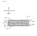
- the electrostatic capacity-type sensor 1 comprises a pair of sensor elements 20a, 20b, a reference member 40, and restraint members 41a, 41b.
- the reference member 40 is made of polyimide, and assumes a band shape extending horizontally.
- the sensor element 20a and the sensor element 20b are arranged above and below of the reference member 40, respectively.
- Each of the pair of sensor elements 20a, 20b consists of the dielectric film 2 and the pair of electrodes 3a, 3b.
- the dielectric film 2 and the pair of electrodes 3a, 3b are the same as those in the first embodiment, so that the explanation thereof is omitted.
- the sensor element 20a is arranged such that the electrode 3b contacts the upper side of the reference member 40.
- the electrode 3b of the sensor element 20a and the upper side of the reference member 40 are fixed to each other by an adhesive.
- the sensor element 20b is arranged such that the electrode 3a contacts the under side of the reference member 40.
- the electrode 3a of the sensor element 20b and the under side of the reference member 40 are fixed to each other by an adhesive.
- Each of the restraint members 41a, 41b is made of polyimide, and assumes a band shape extending horizontally.
- the restraint member 41a is fixed to the upper-side of the electrode 3a of the sensor element 20a by an adhesive.
- the restraint member 41b is fixed to the under-side of the electrode 3b of the sensor element 20b by an adhesive.
- Fig. 6a is a sectional view of the electrostatic capacity-type sensor during bending-deformation in the upward (+) direction.
- Fig.6b is a sectional view of the electrostatic capacity-type sensor during bending-deformation in the downward (-) direction. As shown in Fig.
- Table 1 shows collectively respective changes (increase: +, decrease: -) in the film thickness of the dielectric film 2 of the sensor elements 20a, 20b.
- Bending-deformation Upward direction +
- Bending-deformation Downward direction -
- Sensor element 20a Compressive - Tensile +
- Sensor element 20b Tensile + Compressive - (1) - (2) -- ++
- the increase/decrease in the film thickness of the dielectric film 2 is reverse with respect to the bending-deformation. That is, the sensor elements 20a, 20b have a symmetry relationship with the reference member 40.
- a change in the capacitance of the sensor element 20a is ⁇ C a
- a change in the capacitance of the sensor element 20b is ⁇ C b
- the bending-deformation can be surely detected based on the value of " ⁇ C a - ⁇ C b .”
- the electrostatic capacity-type sensor 1 of this embodiment has a high sensibility and provides little malfunction and erroneous discrimination.
- the restraint members 41a and 41b are arranged on the surface of the sensor elements 20a and 20b, respectively. Hence, the change in the film thickness of the dielectric film 2 during bending-deformation becomes larger, so that the bending-deformation is easily detected.
- a cover film made of an insulating material may be arranged such that it covers the whole of the reference member 40, and sensor elements 20a, 20b. Covering the externally-exposed electrodes 3a, 3b with the cover film allows the surface of the electrostatic capacity-type sensor 1 to be an insulator, and the weather resistance to be effectively improved.
- a cover film an elastically-deformable and flexible elastomer-thin-film and the like are suitable.
- the material and thickness of the reference member 40 may be the same as or different from those of the restraint members 41a and 41b.
- the present invention will be more specifically explained.
- the electrostatic capacity-type sensor 1 of the above-mentioned first embodiment see Figs. 2 and 3
- the response properties to various deformations have been evaluated.
- the electrostatic capacity-type sensor 1 has been prepared in the following manner.
- the dielectric film has been prepared. That is, 100 parts by weight (hereafter, abbreviated as parts) of acrylic rubber (made by Nippon Zeon Co., Ltd.
- NIPPOLE (trademark) AR51”) 1 part of stearic acid as processing aid (made by Kao Corporation "LUNAC (trademark) S30"), 2.5 parts of zinc dimethylcarbamate as vulcanization accelerator (made by Ouchi Shinko Chemical Industrial Co., Ltd. "NOCCELAR (trademark) PZ”), and 0.5 parts of ferric dimetylcarbamate (made by Ouchi Shinko Chemical Industrial Co., Ltd. "NOCCELAR TTFE”) have been mixed and dispersed in a roll kneader to prepare an elastomer composition.
- the elastomer composition thus prepared has been molded into a thin-sheet shape, and then packed into a mold, where the composition has been press crosslinked at 170°C for about 30 minutes to obtain a thin film-shaped dielectric film.
- an unvulcanized electrode has been prepared. That is, 20 parts of ketjen black (made by Lion Corporation "KETJEN600JD", average particle diameter about 40 ⁇ m) as conductive filler, 2.5 parts of zinc dimethyl carbamate as vulcanization accelerator (same as above), and 0. 5 parts of ferric dimethyl carbamate (same as above) have been added to a solution in which 100 parts of acrylic rubber (same as above) has been dissolved into a methyl ethyl ketone (MEK), and then the solution, to which chemicals have been added, has been mixed and dispersed in a dyno mill to obtain a coating material.
- ketjen black made by Lion Corporation "KETJEN600JD", average particle diameter about 40 ⁇ m
- zinc dimethyl carbamate as vulcanization accelerator
- ferric dimethyl carbamate as above
- the coating material has been molded into a thin-film shape by a bar coating method to obtain an unvulcanized electrode. Then, the unvulcanized electrode has been arranged on the surface of the pair of the dielectric films thus prepared, whereby the electrode and the dielectric films have been vulcanized and adhered to each other by pressing them at 170°C for about 30 minutes.
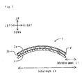
- the above-mentioned electrostatic capacity-type sensor 1 has been bending-deformed to measure a change in the capacitance versus the deformation amount.
- the term "deformation amount” means a difference (L1) between the initial length L0 in the horizontal direction and the length during bending-deformation, as shown in Fig. 7 .
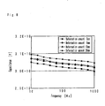
- Fig. 8 shows a change in capacitance versus a frequency due to the difference in the deformation amount.
- "E-10" in the axis of ordinate means “10 -10 " (same as that in the following figures).
- "3.0E-10" indicates “3.0 x 10 -10 .”
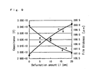
- Fig. 9 shows a change in capacitance and film thickness (distance between electrodes) versus the deformation amount.
- the electrostatic capacity-type sensor of the present invention it has been confirmed that the bending-deformation can be detected. Further, even when the bending-deformation has been repeated, the dielectric film has not been separated from the electrode, expanding/contracting with the dielectric film. This has confirmed that the electrostatic capacity-type sensor of the present invention is excellent in durability.
- Fig. 10 shows a change in capacitance versus a frequency due to the difference in the compression amount. As shown in Fig. 10 , in any of frequencies 1000 through 10000 Hz, the capacitance became larger with the increase of the compression amount. Further, Fig.
- the response properties to the impact from the surface of the bumper cover has been evaluated.
- the electrostatic capacity-type sensor 1 has been mounted by permitting the restraint member 4 to adhere to the under side of the bumper cover.
- an acceleration sensor has been arranged near the center of the electrostatic capacity-type sensor 1 in the longitudinal direction.
- the impedance and the acceleration have been measured. The results are shown in Fig. 12 .
- the value of the primary differential of the change in impedance (Z) is collectively shown.
- the impedance has rapidly dropped with respect to the impact by the hammer. That is, the response delay to the impact is little, so that the response properties of the electrostatic capacity-type sensor of the present invention is high.
- the electrostatic capacity-type sensor of the present invention is useful for the detection of vehicle impact also in view of the speed of the response properties.
- the impedance has been measured at various temperatures 30°C, 50°C, 80°C, 100°C, thereby examining the temperature dependence of the impedance.
- the results are shown in Fig. 13 .
- As shown in Fig. 13 with the rise of the temperature, the impedance has dropped in a low-frequency region. The reason is considered as follows.
- the impedance (Z) can be expressed as in the equation (II).
- the impedance is changed depending on the frequency, the term ( ⁇ C) based on the capacitance is dominant over the impedance, and thus an influence by the direct-current resistance R is little.
- the impedance drops with the rise of temperature, and at the same time, a frequency region in which the impedance exhibits a constant value spreads wide.
- the term of the direct-current resistance R having no frequency dependence shows a factor dominant over the impedance, and the drop of the impedance means the decrease of the direct-current resistance R.
- the direct-current resistance R decreases due to the rise of temperature to cause the impedance in a low-frequency region to be lowered.
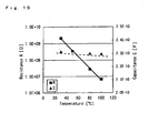
- Fig. 15 shows results from the R and the C determined by the regression analysis of Fig. 13 .
- the proportional relationship between the temperature and the R is obtained in a low-frequency region.
- understanding the relationship between the temperature and the R in a low-frequency region allows the decrease in the capacitance C associated with the increase in the film thickness due to the thermal expansion of the elastomer (dielectric film) at a high temperature to be corrected. That is, according to the electrostatic capacity-type sensor of the present invention, the deformation can be precisely detected utilizing the self-temperature compensating function without depending on the temperature of working environment.
- the above-mentioned electrostatic capacity-type sensor 1 has been arranged such that the longitudinal direction thereof became vertical direction. Then, the sensor is permitted to be bent horizontally with respect to the restraint member 4, thereby measuring a change in the capacitance versus the deflection amount.
- Fig. 16 shows a pattern diagram of this test. As shown in Fig. 16 , the electrostatic capacity-type sensor 1 has been permitted to be bent in the left direction and the right direction from the initial state (before deformation, the length: L0). Now, the bending-deformation in the left direction has been defined as the concave bending and that in the right direction as the convex bending. Further, the deflection amount L2 has been calculated from the equations (a) through (e) as shown in Fig.
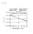
- Fig. 18 shows a change in capacitance (1/C) versus the deflection amount.
- the deflection amount in the convex bending is shown in a positive value, while that in the concave bending is shown in a negative value.
- the phenomenon of the change in capacitance versus the deflection amount became reverse. For example, it is considered that for the convex bending, a compressive stress is applied to the dielectric film 2, the distance between the electrodes became small with the increase of the deflection amount to cause the capacitance (C) to become large.
- the film thickness (distance between the electrodes) became large with the increase of the deflection amount to cause the capacitance (C) to become small.
- the direction and amount of deformation can be discriminated based on the phenomenon of the change in capacitance.
- the electrostatic capacity-type sensor of the present invention can be applied to various applications including a face-pressure sensor for soft surface such as artificial skin, motion capture for detecting human motion, information input device such as keyboard, as well as sitting sensor, sensor for detecting vehicle crash, and face-pressure distribution sensor for bed.
Landscapes
- Engineering & Computer Science (AREA)
- Power Engineering (AREA)
- Physics & Mathematics (AREA)
- General Physics & Mathematics (AREA)
- Measurement Of Length, Angles, Or The Like Using Electric Or Magnetic Means (AREA)
- Force Measurement Appropriate To Specific Purposes (AREA)
- Measuring Fluid Pressure (AREA)
Claims (7)
- Capteur à capacité électrostatique (1), qui comprend un film diélectrique (2) composé d'un élastomère disposé entre une paire d'électrodes (3a, 3b) et qui détecte une déformation sur la base d'un changement de capacité électrostatique entre ladite paire d'électrodes (3a, 3b), ledit capteur à capacité électrostatique (1) étant caractérisé en ce que :ladite paire d'électrodes (3a, 3b) est constituée d'une composition d'élastomère contenant un élastomère (101) et une charge conductrice (102) qui est mélangée dans ledit élastomère (101) et qui est composée d'un matériau carboné ;sur une courbe de percolation indiquant une relation entre la quantité de mélange de ladite charge conductrice (102) et une résistance électrique de ladite composition d'élastomère, la quantité de mélange (fraction volumique critique : Φc) de ladite charge conductrice (102) à un premier point de flexion, où la résistance électrique diminue pour provoquer une transition entre isolant et conducteur, est inférieure ou égale à 25 % en volume ;le module de Young de ladite paire d'électrodes (3a, 3b) se trouve dans l'intervalle allant de 0,1 MPa à 10 MPa ; etladite paire d'électrodes (3a, 3b) peut se dilater/se contracter en fonction de la déformation dudit film diélectrique (2) et sa conductivité change peu même lors d'une dilatation et d'une contraction.
- Capteur à capacité électrostatique (1) selon la revendication 1, dans lequel ledit élastomère utilisé comme matériau dudit film diélectrique (2) comprend un ou plusieurs composés choisis dans le groupe constitué d'un caoutchouc de silicone, d'un caoutchouc de copolymère d'acrylonitrile-butadiène, d'un caoutchouc acrylique, d'un caoutchouc d'épichlorohydrine, d'un polyéthylène chlorosulfoné, d'un polyéthylène chloré et d'un caoutchouc d'uréthane.
- Capteur à capacité électrostatique (1) selon la revendication 1, dans lequel ledit élastomère (101) utilisé comme matériau de ladite paire d'électrodes (3a, 3b) comprend un ou plusieurs composés choisis dans le groupe constitué d'un caoutchouc de silicone, d'un caoutchouc de copolymère d'éthylène-propylène, d'un caoutchouc naturel, un caoutchouc de copolymère de styrène-butadiène, d'un caoutchouc de copolymère d'acrylonitrile-butadiène, d'un caoutchouc acrylique, d'un caoutchouc d'épichlorohydrine, d'un polyéthylène chlorosulfoné, d'un polyéthylène chloré et d'un caoutchouc d'uréthane.
- Capteur à capacité électrostatique (1) selon la revendication 1, dans lequel un élément de retenue (4) servant à modérer une déformation élastique d'une surface d'au moins l'une parmi ladite paire d'électrodes (3a, 3b), qui peut être déformée par flexion élastique, est disposé sur ladite surface.
- Capteur à capacité électrostatique (1) selon la revendication 4, dans lequel ledit élément de retenue (4) servant à modérer une déformation élastique d'une surface de l'une parmi ladite paire d'électrodes (3a, 3b) est disposé sur ladite surface ; et
lors d'une déformation par flexion, la direction de ladite déformation par flexion peut être distinguée sur la base d'un changement de capacité électrostatique entre ladite paire d'électrodes (3a, 3b). - Capteur à capacité électrostatique (1) selon la revendication 1, dans lequel une paire d'éléments de détection (20a, 20b) comprenant ledit film diélectrique (2) et ladite paire d'électrodes (3a, 3b) est disposée sur les deux côtés respectifs d'un élément de référence en forme de plaque pouvant être déformé par flexion élastique (40) ; et
du fait que l'augmentation/la diminution de l'épaisseur dudit film diélectrique (2) sur les deux côtés dudit élément de référence (40) s'inverse lors d'une déformation par flexion, ladite déformation par flexion est détectée sur la base de la différence entre un changement de capacité électrostatique dans l'un desdits éléments de détection (20a) et un changement de capacité électrostatique dans l'autre desdits éléments de détection (20b). - Capteur à capacité électrostatique (1) selon la revendication 6, dans lequel des éléments de retenue (41a, 41b) servant à modérer la déformation élastique des surfaces respectives desdits éléments de détection (20a, 20b) sont en outre disposés sur lesdites surfaces.
Applications Claiming Priority (1)
| Application Number | Priority Date | Filing Date | Title |
|---|---|---|---|
| JP2007183091A JP5496446B2 (ja) | 2007-07-12 | 2007-07-12 | 静電容量型センサ |
Publications (3)
| Publication Number | Publication Date |
|---|---|
| EP2015043A2 EP2015043A2 (fr) | 2009-01-14 |
| EP2015043A3 EP2015043A3 (fr) | 2009-11-25 |
| EP2015043B1 true EP2015043B1 (fr) | 2012-11-21 |
Family
ID=39832036
Family Applications (1)
| Application Number | Title | Priority Date | Filing Date |
|---|---|---|---|
| EP08009644A Active EP2015043B1 (fr) | 2007-07-12 | 2008-05-27 | Capteur à capacité électrostatique |
Country Status (3)
| Country | Link |
|---|---|
| US (1) | US8451011B2 (fr) |
| EP (1) | EP2015043B1 (fr) |
| JP (1) | JP5496446B2 (fr) |
Families Citing this family (81)
| Publication number | Priority date | Publication date | Assignee | Title |
|---|---|---|---|---|
| JP5568206B2 (ja) * | 2006-09-15 | 2014-08-06 | 東海ゴム工業株式会社 | 変形センサ |
| US7958789B2 (en) * | 2008-08-08 | 2011-06-14 | Tokai Rubber Industries, Ltd. | Capacitive sensor |
| JP4650538B2 (ja) * | 2008-08-08 | 2011-03-16 | 東海ゴム工業株式会社 | 静電容量型センサ |
| US8915151B2 (en) * | 2009-06-05 | 2014-12-23 | Sungkyunkwan University Foundation For Corporate Collaboration | Active skin for conformable tactile interface |
| US8661893B2 (en) * | 2010-06-29 | 2014-03-04 | Orthosensor Inc. | Prosthetic component having a compliant surface |
| US8714009B2 (en) | 2010-06-29 | 2014-05-06 | Orthosensor Inc. | Shielded capacitor sensor system for medical applications and method |
| US9259179B2 (en) | 2012-02-27 | 2016-02-16 | Orthosensor Inc. | Prosthetic knee joint measurement system including energy harvesting and method therefor |
| US9462964B2 (en) | 2011-09-23 | 2016-10-11 | Orthosensor Inc | Small form factor muscular-skeletal parameter measurement system |
| US8720270B2 (en) | 2010-06-29 | 2014-05-13 | Ortho Sensor Inc. | Prosthetic component for monitoring joint health |
| US8679186B2 (en) | 2010-06-29 | 2014-03-25 | Ortho Sensor Inc. | Hermetically sealed prosthetic component and method therefor |
| JP2011017626A (ja) * | 2009-07-09 | 2011-01-27 | Sony Corp | 力学量検知部材及び力学量検知装置 |
| WO2011037078A1 (fr) | 2009-09-28 | 2011-03-31 | 東海ゴム工業株式会社 | Ensemble capteur et module de capteur |
| JP5448910B2 (ja) * | 2010-02-18 | 2014-03-19 | 東海ゴム工業株式会社 | 導電層の形成方法 |
| DE102010010348A1 (de) * | 2010-03-05 | 2011-09-08 | Albert-Ludwigs-Universität Freiburg | Implantierbare Vorrichtung zum Erfassen einer Gefäßwanddehnung |
| US9332943B2 (en) | 2011-09-23 | 2016-05-10 | Orthosensor Inc | Flexible surface parameter measurement system for the muscular-skeletal system |
| KR101346416B1 (ko) | 2010-05-19 | 2014-01-02 | 도카이 고무 고교 가부시키가이샤 | 도전막, 및 그것을 사용한 트랜스듀서, 플렉시블 배선판 |
| JP5054153B2 (ja) * | 2010-05-31 | 2012-10-24 | パナソニック株式会社 | マッサージ機 |
| JP5465121B2 (ja) * | 2010-07-29 | 2014-04-09 | 東海ゴム工業株式会社 | 配線体接続構造体 |
| WO2012050128A1 (fr) * | 2010-10-13 | 2012-04-19 | 東海ゴム工業株式会社 | Matériau conducteur souple et transducteur, carte à circuit imprimé souple, et protection électromagnétique utilisant ledit matériau conducteur souple |
| JP5486683B2 (ja) * | 2010-11-04 | 2014-05-07 | 東海ゴム工業株式会社 | 曲げセンサ |
| US9414940B2 (en) | 2011-09-23 | 2016-08-16 | Orthosensor Inc. | Sensored head for a measurement tool for the muscular-skeletal system |
| US9839374B2 (en) | 2011-09-23 | 2017-12-12 | Orthosensor Inc. | System and method for vertebral load and location sensing |
| US8911448B2 (en) | 2011-09-23 | 2014-12-16 | Orthosensor, Inc | Device and method for enabling an orthopedic tool for parameter measurement |
| KR101310012B1 (ko) * | 2011-12-19 | 2013-09-24 | 성균관대학교산학협력단 | 복합형 다축센서 |
| US9844335B2 (en) | 2012-02-27 | 2017-12-19 | Orthosensor Inc | Measurement device for the muscular-skeletal system having load distribution plates |
| JP5896353B2 (ja) * | 2012-03-28 | 2016-03-30 | 住友理工株式会社 | 静電容量型センサ装置 |
| JP5876358B2 (ja) | 2012-03-30 | 2016-03-02 | 国立大学法人九州大学 | 歩行運動補助具 |
| JP5986445B2 (ja) | 2012-07-20 | 2016-09-06 | 国立大学法人九州大学 | 歩行用遊脚振子運動補助具およびアシスト力の制御方法 |
| BR112015009951A2 (pt) * | 2012-11-06 | 2017-07-11 | Koninklijke Philips Nv | dispositivo de acionamento para mover equipamentos, sistema de exame médico, sensor de uma área sensível ao toque, método para mover equipamentos, elemento de programa de computador, e, meio legível por computador |
| US20140135744A1 (en) | 2012-11-09 | 2014-05-15 | Orthosensor Inc | Motion and orientation sensing module or device for positioning of implants |
| JP5551228B2 (ja) * | 2012-11-29 | 2014-07-16 | 東海ゴム工業株式会社 | パワーシート装置 |
| JP2014167415A (ja) * | 2013-02-28 | 2014-09-11 | Tokai Rubber Ind Ltd | 静電容量式近接センサ装置 |
| WO2014157627A1 (fr) | 2013-03-29 | 2014-10-02 | バンドー化学株式会社 | Feuille de capteur capacitif et capteurs capacitifs |
| JP2014219214A (ja) * | 2013-05-01 | 2014-11-20 | バンドー化学株式会社 | 静電容量型センサシート及び静電容量型センサ |
| JP2014219263A (ja) * | 2013-05-08 | 2014-11-20 | バンドー化学株式会社 | 静電容量型センサシート及び静電容量型センサ |
| DE102013107271A1 (de) * | 2013-07-09 | 2015-01-15 | Institut Für Verbundwerkstoffe Gmbh | Sensor zur Erfassung druckabhängiger Messwerte in Dünnschichtbauweise |
| US8941392B1 (en) | 2013-08-17 | 2015-01-27 | Bend Labs, Inc. | Angular displacement sensor of compliant material |
| JP2015045623A (ja) * | 2013-08-29 | 2015-03-12 | バンドー化学株式会社 | 静電容量型センサシート及び静電容量型センサ |
| KR102143352B1 (ko) * | 2013-12-13 | 2020-08-11 | 엘지디스플레이 주식회사 | 햅틱 일체형 터치스크린, 이의 제조방법 및 이를 포함하는 표시장치 |
| DE102014201289A1 (de) * | 2014-01-24 | 2015-07-30 | Fraunhofer-Gesellschaft zur Förderung der angewandten Forschung e.V. | Tastatur und System mit einer Tastatur |
| US20150277617A1 (en) * | 2014-03-28 | 2015-10-01 | Paul Gwin | Flexible sensor |
| JP2015206783A (ja) * | 2014-04-08 | 2015-11-19 | 学校法人 龍谷大学 | 曲げ量計測装置 |
| WO2015156174A1 (fr) * | 2014-04-09 | 2015-10-15 | バンドー化学株式会社 | Dispositif capteur |
| WO2015172897A1 (fr) * | 2014-05-12 | 2015-11-19 | Koninklijke Philips N.V. | Capteur en composite de silicone pour le mesure de la frequence cardiaque |
| JP6257444B2 (ja) * | 2014-05-16 | 2018-01-10 | 住友理工株式会社 | 関節角度センサおよび関節角度検出方法 |
| JP6325482B2 (ja) * | 2015-04-06 | 2018-05-16 | バンドー化学株式会社 | 静電容量型センサシート及びセンサ装置 |
| US9612102B2 (en) | 2015-04-17 | 2017-04-04 | Bend Labs, Inc | Compliant multi-region angular displacement and strain sensors |
| KR102440208B1 (ko) * | 2015-09-03 | 2022-09-05 | 엘지이노텍 주식회사 | 압력 감지 소자 |
| JP2017053801A (ja) * | 2015-09-11 | 2017-03-16 | 藤倉ゴム工業株式会社 | ストレッチャブル静電容量型センサ |
| MX2018006490A (es) | 2015-12-17 | 2018-08-15 | Avent Inc | Bomba de infusion con sensor de alargamiento. |
| KR102632730B1 (ko) * | 2016-03-23 | 2024-02-06 | 삼성디스플레이 주식회사 | 전자 장치 |
| US10959644B2 (en) | 2016-03-24 | 2021-03-30 | Bend Labs Inc. | Compliant sensors for force sensing |
| JP6746347B2 (ja) * | 2016-03-30 | 2020-08-26 | 住友理工株式会社 | 心肺蘇生術補助装置 |
| KR102553036B1 (ko) * | 2016-06-29 | 2023-07-07 | 엘지이노텍 주식회사 | 압력 감지 센서 |
| FI127245B (en) * | 2016-07-11 | 2018-02-15 | Forciot Oy | Force and / or pressure sensor |
| JP2018054590A (ja) * | 2016-09-21 | 2018-04-05 | 東洋紡株式会社 | 伸縮性コンデンサおよび変形センサ |
| TWI623732B (zh) * | 2016-12-29 | 2018-05-11 | 台灣艾華電子工業股份有限公司 | 分層異向位移型拉伸感測器 |
| CN108303018B (zh) * | 2017-01-13 | 2019-11-19 | 台湾艾华电子工业股份有限公司 | 分层异向位移型拉伸传感器 |
| JP6781648B2 (ja) * | 2017-03-09 | 2020-11-04 | 正毅 千葉 | 誘電エラストマーセンサシステムおよび誘電エラストマーセンサ要素 |
| JP7068569B2 (ja) * | 2017-06-29 | 2022-05-17 | グンゼ株式会社 | 引張センサ |
| JP6574831B2 (ja) * | 2017-12-29 | 2019-09-11 | バンドー化学株式会社 | 静電容量型センサシート及び静電容量型センサ |
| CN109933232A (zh) * | 2018-01-16 | 2019-06-25 | 京东方科技集团股份有限公司 | 触控传感器及电子装置 |
| JP2018091875A (ja) * | 2018-03-22 | 2018-06-14 | バンドー化学株式会社 | シート状物、静電容量型センサシート、及び、衣服 |
| WO2020111073A1 (fr) * | 2018-11-28 | 2020-06-04 | バンドー化学株式会社 | Corps de capteur et dispositif de capteur |
| WO2020227452A1 (fr) | 2019-05-06 | 2020-11-12 | Liquid Wire Inc. | Structures conductrices déformables et procédés de fabrication |
| EP3980739B1 (fr) * | 2019-06-05 | 2026-02-04 | Liquid Wire Inc. | Capteurs déformables à retenue sélective |
| US11460362B2 (en) * | 2019-07-23 | 2022-10-04 | Toyota Motor Engineering & Manufacturing North America, Inc. | Flexible printed pressure transducer with sensor diffusion stack materials and methods incorporating the same |
| US11340123B2 (en) * | 2019-08-12 | 2022-05-24 | Parker-Hannifin Corporation | Electroactive polymer pressure sensor having corrugating capacitor |
| JP7386445B2 (ja) * | 2019-08-27 | 2023-11-27 | パナソニックIpマネジメント株式会社 | 荷重センサ |
| HUE058145T2 (hu) * | 2019-09-06 | 2022-07-28 | Forciot Oy | Deformálható érzékelõ |
| CN114585873A (zh) * | 2019-11-15 | 2022-06-03 | 郡是株式会社 | 层叠型弯曲传感器以及机电转换装置 |
| JP2021081237A (ja) * | 2019-11-15 | 2021-05-27 | グンゼ株式会社 | 積層型曲げセンサ及び機械電気変換装置 |
| JP7364496B2 (ja) * | 2020-03-04 | 2023-10-18 | グンゼ株式会社 | 積層型曲げセンサ及び機械電気変換装置 |
| US12247847B2 (en) | 2020-07-29 | 2025-03-11 | Bend Labs, Inc. | Electrode and shielding systems and methods for compliant sensors |
| US12542244B2 (en) | 2020-11-03 | 2026-02-03 | Zhi Neng Rong Dian (Beijing) Technology Co., Ltd | Flexible variable capacitor and method for preparation thereof |
| JP7254433B2 (ja) * | 2021-05-31 | 2023-04-10 | Nissha株式会社 | ロボットハンドの触覚センサ付き指およびこれを用いた触覚センサ付きロボットハンド |
| CN113686467B (zh) * | 2021-08-19 | 2023-07-07 | 成都蕊感微电子有限公司 | 电容式压力传感器及其制备方法、压力检测系统 |
| JP2023072610A (ja) * | 2021-11-12 | 2023-05-24 | マクセルクレハ株式会社 | 圧力センサおよび圧力センサユニット |
| KR102753462B1 (ko) * | 2022-04-13 | 2025-01-09 | 재단법인대구경북과학기술원 | 사용자 입력 장치 |
| CN115112272A (zh) * | 2022-06-16 | 2022-09-27 | 中国人民解放军国防科技大学 | 一种柔性力传感器、柔性力/磁场复合传感器及机器人 |
| CN121794553A (zh) * | 2023-09-27 | 2026-04-03 | 日东电工株式会社 | 电容式传感器 |
Family Cites Families (22)
| Publication number | Priority date | Publication date | Assignee | Title |
|---|---|---|---|---|
| US3814998A (en) * | 1973-05-18 | 1974-06-04 | Johnson Service Co | Pressure sensitive capacitance sensing element |
| JPS5824921B2 (ja) * | 1977-12-30 | 1983-05-24 | 信越ポリマ−株式会社 | 感圧抵抗素子 |
| JPS5842901A (ja) * | 1981-09-07 | 1983-03-12 | Kureha Chem Ind Co Ltd | 歪測定方法及びこれに使用するための装置 |
| JPS5954904A (ja) * | 1982-09-24 | 1984-03-29 | Hitachi Ltd | 容量型ひずみゲ−ジ |
| JPS59168329A (ja) * | 1983-03-16 | 1984-09-22 | Fuji Electric Co Ltd | 静電容量式荷重測定器 |
| JPS63150185A (ja) * | 1986-12-12 | 1988-06-22 | ダイキン工業株式会社 | ロボツトにおける角度制御装置 |
| US5090246A (en) * | 1990-09-19 | 1992-02-25 | Johnson Service Corp. | Elastomer type low pressure sensor |
| JPH05288619A (ja) | 1992-04-07 | 1993-11-02 | Youji Yamada | 静電容量式触覚センサ |
| US5424650A (en) * | 1993-09-24 | 1995-06-13 | Rosemont Inc. | Capacitive pressure sensor having circuitry for eliminating stray capacitance |
| JP3480535B2 (ja) * | 1994-09-05 | 2003-12-22 | 日機装株式会社 | 帯電防止性ゴム組成物 |
| JPH095014A (ja) * | 1995-06-19 | 1997-01-10 | Hirano Denshi:Kk | 曲げセンサ |
| JP3418561B2 (ja) * | 1997-12-26 | 2003-06-23 | 豊明 木村 | 導電性粒子−高分子系による歪みセンサー |
| JP2002340700A (ja) * | 2001-05-14 | 2002-11-27 | Matsushita Electric Ind Co Ltd | 圧電センサ |
| JP3983638B2 (ja) * | 2002-09-24 | 2007-09-26 | ニッタ株式会社 | センサシート |
| DE10248761B4 (de) * | 2002-10-18 | 2013-10-02 | Wilhelm Karmann Gmbh | Kapazitiv messender Sensor und Detektionseinrichtung mit einer kapazitiven Sensorik zum Detektieren einer Einklemmsituation |
| US7320676B2 (en) * | 2003-10-02 | 2008-01-22 | Medtronic, Inc. | Pressure sensing in implantable medical devices |
| JP4141426B2 (ja) | 2004-03-29 | 2008-08-27 | 三洋電機株式会社 | 静電容量型圧力センサー及びこれを用いた心拍/呼吸計測装置 |
| WO2006091631A2 (fr) * | 2005-02-23 | 2006-08-31 | Watkins Kenneth S Jr | Detecteur de degradation pour produits environnementalement fragiles et procede d'utilisation |
| TWI381399B (zh) * | 2005-07-12 | 2013-01-01 | Sulzer Metco Canada Inc | 性能增進之導電性填料及由該填料製成的聚合物 |
| JP5166714B2 (ja) | 2006-09-15 | 2013-03-21 | 東海ゴム工業株式会社 | センサー用架橋エラストマー体およびその製法 |
| JP5568206B2 (ja) | 2006-09-15 | 2014-08-06 | 東海ゴム工業株式会社 | 変形センサ |
| DE602007013162D1 (de) | 2006-10-25 | 2011-04-28 | Tokai Rubber Ind Ltd | Verformungssensor |
-
2007
- 2007-07-12 JP JP2007183091A patent/JP5496446B2/ja active Active
-
2008
- 2008-05-27 EP EP08009644A patent/EP2015043B1/fr active Active
- 2008-06-03 US US12/155,387 patent/US8451011B2/en active Active
Also Published As
| Publication number | Publication date |
|---|---|
| US8451011B2 (en) | 2013-05-28 |
| US20090015270A1 (en) | 2009-01-15 |
| JP2009020006A (ja) | 2009-01-29 |
| EP2015043A2 (fr) | 2009-01-14 |
| EP2015043A3 (fr) | 2009-11-25 |
| JP5496446B2 (ja) | 2014-05-21 |
Similar Documents
| Publication | Publication Date | Title |
|---|---|---|
| EP2015043B1 (fr) | Capteur à capacité électrostatique | |
| EP1901311B1 (fr) | Corps en élastomère réticulé | |
| EP1901048B1 (fr) | Capteur de déformation | |
| EP2905574B1 (fr) | Feuille de capteur de type capacitif, son procédé de fabrication et capteur | |
| US5693886A (en) | Pressure sensor | |
| KR101346416B1 (ko) | 도전막, 및 그것을 사용한 트랜스듀서, 플렉시블 배선판 | |
| JP6696885B2 (ja) | 圧電センサ | |
| JP4650538B2 (ja) | 静電容量型センサ | |
| EP2154503B1 (fr) | Capteur capacitif de déformation | |
| US20170315165A1 (en) | Capacitive sensor, sensor sheet, and method for manufacturing capacitive sensor | |
| EP2743317A1 (fr) | Matériau conducteur flexible | |
| JP5636290B2 (ja) | 感圧センサ | |
| KR101210937B1 (ko) | 압력 감응 소자 및 이를 이용한 촉각 센서 | |
| KR20130001305A (ko) | 유연 도전 재료, 및 그것을 사용한 트랜스듀서, 플렉시블 배선판, 전자파 실드 | |
| JP5474331B2 (ja) | 誘電膜、およびそれを用いたアクチュエータ、センサ、トランスデューサ | |
| US9972768B2 (en) | Actuator structure and method | |
| WO2017057598A1 (fr) | Capteur capacitif | |
| JP5662637B2 (ja) | 荷重センサ | |
| JP3593184B2 (ja) | 感圧センサー | |
| TW202009454A (zh) | 感測器系統及使用其之測定裝置 | |
| JP5577022B2 (ja) | センサ用複合材料および変形センサ | |
| JP2020187053A (ja) | 感圧センサシートおよび感圧センサ | |
| JP2008241528A (ja) | 変形センサシステム | |
| JP2015200501A (ja) | 歪み計測装置、歪み量及び歪み方向計測方法 | |
| JP2008286747A (ja) | 変形センサシステム |
Legal Events
| Date | Code | Title | Description |
|---|---|---|---|
| PUAI | Public reference made under article 153(3) epc to a published international application that has entered the european phase |
Free format text: ORIGINAL CODE: 0009012 |
|
| AK | Designated contracting states |
Kind code of ref document: A2 Designated state(s): AT BE BG CH CY CZ DE DK EE ES FI FR GB GR HR HU IE IS IT LI LT LU LV MC MT NL NO PL PT RO SE SI SK TR |
|
| AX | Request for extension of the european patent |
Extension state: AL BA MK RS |
|
| PUAL | Search report despatched |
Free format text: ORIGINAL CODE: 0009013 |
|
| AK | Designated contracting states |
Kind code of ref document: A3 Designated state(s): AT BE BG CH CY CZ DE DK EE ES FI FR GB GR HR HU IE IS IT LI LT LU LV MC MT NL NO PL PT RO SE SI SK TR |
|
| AX | Request for extension of the european patent |
Extension state: AL BA MK RS |
|
| 17P | Request for examination filed |
Effective date: 20100525 |
|
| AKX | Designation fees paid |
Designated state(s): DE |
|
| RBV | Designated contracting states (corrected) |
Designated state(s): DE |
|
| GRAP | Despatch of communication of intention to grant a patent |
Free format text: ORIGINAL CODE: EPIDOSNIGR1 |
|
| GRAS | Grant fee paid |
Free format text: ORIGINAL CODE: EPIDOSNIGR3 |
|
| GRAA | (expected) grant |
Free format text: ORIGINAL CODE: 0009210 |
|
| AK | Designated contracting states |
Kind code of ref document: B1 Designated state(s): DE |
|
| REG | Reference to a national code |
Ref country code: DE Ref legal event code: R096 Ref document number: 602008020188 Country of ref document: DE Effective date: 20130117 |
|
| PLBE | No opposition filed within time limit |
Free format text: ORIGINAL CODE: 0009261 |
|
| STAA | Information on the status of an ep patent application or granted ep patent |
Free format text: STATUS: NO OPPOSITION FILED WITHIN TIME LIMIT |
|
| 26N | No opposition filed |
Effective date: 20130822 |
|
| REG | Reference to a national code |
Ref country code: DE Ref legal event code: R097 Ref document number: 602008020188 Country of ref document: DE Effective date: 20130822 |
|
| REG | Reference to a national code |
Ref country code: DE Ref legal event code: R084 Ref document number: 602008020188 Country of ref document: DE Effective date: 20140204 |
|
| REG | Reference to a national code |
Ref country code: DE Ref legal event code: R082 Ref document number: 602008020188 Country of ref document: DE Representative=s name: KUHNEN & WACKER PATENT- UND RECHTSANWALTSBUERO, DE |
|
| REG | Reference to a national code |
Ref country code: DE Ref legal event code: R081 Ref document number: 602008020188 Country of ref document: DE Owner name: SUMITOMO RIKO COMPANY LIMITED, KOMAKI-SHI, JP Free format text: FORMER OWNER: TOKAI RUBBER INDUSTRIES, LTD., KOMAKI-SHI, AICHI-KEN, JP Effective date: 20141017 Ref country code: DE Ref legal event code: R082 Ref document number: 602008020188 Country of ref document: DE Representative=s name: KUHNEN & WACKER PATENT- UND RECHTSANWALTSBUERO, DE Effective date: 20141017 |
|
| PGFP | Annual fee paid to national office [announced via postgrant information from national office to epo] |
Ref country code: DE Payment date: 20250402 Year of fee payment: 18 |