EP1901321A2 - Clavier et terminal portable incorporant un tel clavier - Google Patents
Clavier et terminal portable incorporant un tel clavier Download PDFInfo
- Publication number
- EP1901321A2 EP1901321A2 EP07001200A EP07001200A EP1901321A2 EP 1901321 A2 EP1901321 A2 EP 1901321A2 EP 07001200 A EP07001200 A EP 07001200A EP 07001200 A EP07001200 A EP 07001200A EP 1901321 A2 EP1901321 A2 EP 1901321A2
- Authority
- EP
- European Patent Office
- Prior art keywords
- light
- guiding sheet
- light guiding
- key buttons
- key
- Prior art date
- Legal status (The legal status is an assumption and is not a legal conclusion. Google has not performed a legal analysis and makes no representation as to the accuracy of the status listed.)
- Granted
Links
- 239000000758 substrate Substances 0.000 claims abstract description 16
- 239000000463 material Substances 0.000 claims description 7
- XUIMIQQOPSSXEZ-UHFFFAOYSA-N Silicon Chemical compound [Si] XUIMIQQOPSSXEZ-UHFFFAOYSA-N 0.000 claims description 4
- 239000000853 adhesive Substances 0.000 claims description 4
- 230000001070 adhesive effect Effects 0.000 claims description 4
- 238000002347 injection Methods 0.000 claims description 4
- 239000007924 injection Substances 0.000 claims description 4
- 229910052710 silicon Inorganic materials 0.000 claims description 4
- 239000010703 silicon Substances 0.000 claims description 4
- 229920002379 silicone rubber Polymers 0.000 claims description 4
- 239000010410 layer Substances 0.000 description 22
- 238000000034 method Methods 0.000 description 8
- 230000003287 optical effect Effects 0.000 description 3
- 230000003247 decreasing effect Effects 0.000 description 2
- 238000004519 manufacturing process Methods 0.000 description 2
- 238000012986 modification Methods 0.000 description 2
- 230000004048 modification Effects 0.000 description 2
- 239000012790 adhesive layer Substances 0.000 description 1
- 238000005530 etching Methods 0.000 description 1
- 238000000465 moulding Methods 0.000 description 1
- 229920003023 plastic Polymers 0.000 description 1
- 239000004417 polycarbonate Substances 0.000 description 1
- 239000004814 polyurethane Substances 0.000 description 1
- 238000003825 pressing Methods 0.000 description 1
Images

Classifications
-
- H—ELECTRICITY
- H01—ELECTRIC ELEMENTS
- H01H—ELECTRIC SWITCHES; RELAYS; SELECTORS; EMERGENCY PROTECTIVE DEVICES
- H01H13/00—Switches having rectilinearly-movable operating part or parts adapted for pushing or pulling in one direction only, e.g. push-button switch
- H01H13/70—Switches having rectilinearly-movable operating part or parts adapted for pushing or pulling in one direction only, e.g. push-button switch having a plurality of operating members associated with different sets of contacts, e.g. keyboard
- H01H13/83—Switches having rectilinearly-movable operating part or parts adapted for pushing or pulling in one direction only, e.g. push-button switch having a plurality of operating members associated with different sets of contacts, e.g. keyboard characterised by legends, e.g. Braille, liquid crystal displays, light emitting or optical elements
-
- H—ELECTRICITY
- H01—ELECTRIC ELEMENTS
- H01H—ELECTRIC SWITCHES; RELAYS; SELECTORS; EMERGENCY PROTECTIVE DEVICES
- H01H13/00—Switches having rectilinearly-movable operating part or parts adapted for pushing or pulling in one direction only, e.g. push-button switch
- H01H13/70—Switches having rectilinearly-movable operating part or parts adapted for pushing or pulling in one direction only, e.g. push-button switch having a plurality of operating members associated with different sets of contacts, e.g. keyboard
-
- H—ELECTRICITY
- H01—ELECTRIC ELEMENTS
- H01H—ELECTRIC SWITCHES; RELAYS; SELECTORS; EMERGENCY PROTECTIVE DEVICES
- H01H13/00—Switches having rectilinearly-movable operating part or parts adapted for pushing or pulling in one direction only, e.g. push-button switch
- H01H13/70—Switches having rectilinearly-movable operating part or parts adapted for pushing or pulling in one direction only, e.g. push-button switch having a plurality of operating members associated with different sets of contacts, e.g. keyboard
- H01H13/702—Switches having rectilinearly-movable operating part or parts adapted for pushing or pulling in one direction only, e.g. push-button switch having a plurality of operating members associated with different sets of contacts, e.g. keyboard with contacts carried by or formed from layers in a multilayer structure, e.g. membrane switches
-
- H—ELECTRICITY
- H04—ELECTRIC COMMUNICATION TECHNIQUE
- H04B—TRANSMISSION
- H04B1/00—Details of transmission systems, not covered by a single one of groups H04B3/00 - H04B13/00; Details of transmission systems not characterised by the medium used for transmission
- H04B1/38—Transceivers, i.e. devices in which transmitter and receiver form a structural unit and in which at least one part is used for functions of transmitting and receiving
-
- H—ELECTRICITY
- H04—ELECTRIC COMMUNICATION TECHNIQUE
- H04M—TELEPHONIC COMMUNICATION
- H04M1/00—Substation equipment, e.g. for use by subscribers
- H04M1/02—Constructional features of telephone sets
- H04M1/22—Illumination; Arrangements for improving the visibility of characters on dials
-
- H—ELECTRICITY
- H01—ELECTRIC ELEMENTS
- H01H—ELECTRIC SWITCHES; RELAYS; SELECTORS; EMERGENCY PROTECTIVE DEVICES
- H01H2219/00—Legends
- H01H2219/036—Light emitting elements
- H01H2219/044—Edge lighting of layer
-
- H—ELECTRICITY
- H01—ELECTRIC ELEMENTS
- H01H—ELECTRIC SWITCHES; RELAYS; SELECTORS; EMERGENCY PROTECTIVE DEVICES
- H01H2219/00—Legends
- H01H2219/054—Optical elements
- H01H2219/06—Reflector
-
- H—ELECTRICITY
- H01—ELECTRIC ELEMENTS
- H01H—ELECTRIC SWITCHES; RELAYS; SELECTORS; EMERGENCY PROTECTIVE DEVICES
- H01H2219/00—Legends
- H01H2219/054—Optical elements
- H01H2219/062—Light conductor
Definitions
- the present invention relates to a key assembly for a mobile terminal, and a mobile terminal having the same.
- a mobile terminal is one of many portable electronic devices capable of enabling a user to wirelessly transmit/receive data or to process information while being moved. As the mobile terminal becomes lighter and slimmer in order for the user to conveniently carry it, the mobile terminal requires a mechanical structure to implement various functions in a small and limited device.
- FIG. 1 is a sectional view showing a key assembly in accordance with the related art.
- the related art key assembly 1 comprises a plurality of key buttons 2 exposed outside the mobile terminal and is pressably-operated.
- a switch 6 is arranged below the key buttons 2 and is mounted on an upper surface of a circuit board 4, for receiving a signal as the key buttons 2 are pressed.
- a pad 3 is attached to a lower surface of the key buttons 2 and is elastically transformed when the key buttons 2 are pressed, for pressurizing the switch 6 to thereby input a signal.
- a pressurizing protrusion 7 for pressurizing the switch 6 as the key buttons 2 are pressed is disposed at the pad 3.
- the key buttons 2 are arranged on a case 9 so as to be outwardly exposed, and have symbols such as numbers, characters, or other command prompts, on the upper surfaces of the key buttons 2.
- the symbols are printed as a negative type to selectively pass light generated from light emitting diodes (LEDs) 5, which will be explained later, thereby implementing a backlighting of the symbols.
- LEDs light emitting diodes
- a plurality of LEDs 5 for illuminating the key buttons 2 are upwardly protruding near the switches 6 of the circuit board 4.
- the symbols on the key buttons 2 are illuminated by the LEDs 5, so that the user can input the symbols even in a dark place.
- the Korean Patent Publication No. 10-2003-89182 discloses a technique for arranging a light guiding plate on an upper surface of a main board having dome switches, the light guiding plate having passing holes in correspondence with the dome switches.
- the number of the passing holes corresponds to the number of the dome switches, thereby requiring a difficult processing operation. Furthermore, a large amount of light disappears in the light guiding plate, thereby not sufficiently illuminating each of the key buttons.
- Korean Patent Publication No. 10-2005-64351 discloses a technique that a light guiding plate is attached to a lower surface of a keypad and a light emitting device is mounted on an additional circuit board attached to the light guiding plate.
- a light emitting device is installed separately from the main board, an additional structure for fixing the light emitting device and an electric connection unit are required. Accordingly, an entire process is complicated and a fabrication cost is increased.
- a key assembly capable of reducing the number of optical sources and an amount of power consumption by applying a light guiding member to a key assembly, and a mobile terminal having the same are provided.
- a key assembly having a plurality of key buttons, a light guiding sheet arranged below at least one of the plurality of key buttons, a light emitter to generate light into an edge of the light guiding sheet, the light guiding sheet directing light from the light emitter towards at least one of the plurality of key buttons, a circuitry supporting substrate formed below the light guiding sheet; and a plurality of switches formed on the circuitry supporting substrate, each of the plurality of switches corresponding to one of the plurality of key buttons.
- the light guiding sheet overlays an upper portion of each of the plurality of switches.
- the light guiding sheet is arranged below all of the plurality of key buttons and the light guiding sheet directs light from the light emitter towards all of the plurality of key buttons.
- the key assembly includes a reflective layer located at a perimeter of the light guiding sheet for redirecting light from the light emitter away from the perimeter.
- the light emitter may be mounted on an upper surface of the circuitry supporting substrate.
- each of the plurality of switches is formed to have a dome shape
- the light guiding sheet is formed of a flexible material that prevents adjacent switches from being pressed when a switch corresponding to one of the key buttons is pressed.
- the light guiding sheet is attached onto the circuitry supporting substrate by an adhesive or a double sided tape deposited onto a lower surface thereof along an edge thereof.
- a plurality of reflection pattern portions for intensively guiding light from the light emitter to each of the key buttons is formed at a lower surface of the light guiding sheet in correspondence with the plurality of key buttons.
- the plurality of key buttons are formed as an integral pad
- the pad includes an opaque layer forming an appearance and having symbols penetratingly formed in correspondence with numbers or characters to be inputted, the opaque layer defining an upper surface for each of the plurality of buttons.
- the pad also includes a transparent layer formed at a lower surface of the opaque layer and integral with the opaque layer and a plurality of pressurizing protrusions formed at a lower surface of the transparent layer. Each of the pressurizing protrusions correspond to one of the plurality of key buttons and one of the plurality of switches.
- the opaque layer may be formed of a metallic plate and the transparent layer may be formed of silicon or silicon rubber co-injection molded onto the metallic plate.
- a mobile terminal is provided that incorporates one or more of the above features of the key assembly.
- FIG. 2 is a perspective view showing a mobile terminal according to an exemplary embodiment of the present invention.
- a mobile terminal 10 is provided with a terminal body 11 on which a key assembly 20 is installed.
- a display 12 for displaying video information is provided at a front surface of the terminal body 11, and the key assembly 20 is provided at one side of the display 12.
- a receiver or a speaker 13 for outputting a voice signal may be mounted at an upper end of the terminal body 11, and a microphone 14 for inputting a voice signal may be mounted at a lower end of the terminal body 11.
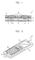
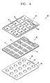
- FIG. 3 is a sectional view taken along line III-III of FIG. 2, and FIG. 4 is a disassembled perspective view of a key assembly of FIG. 2.
- a plurality of key buttons 31 are arranged to be exposed outside the mobile terminal 10 and may be formed as one integrated pad 30.
- the pad 30 includes an opaque layer 32 forming an appearance of key buttons 31 and having symbols 31a penetratingly formed thereon.
- the symbols correspond with numbers or characters to be inputted.
- a transparent layer 33 is integrally formed at a lower surface of the opaque layer 32 and a plurality of pressurizing protrusions 34 is formed at a lower surface of the transparent layer 33, each of which corresponds to one of the key buttons 31.
- the pressurizing protrusion 34 is for pressurizing a switch 51 that will be later explained.
- the opaque layer 32 may be formed of a metallic plate having an excellent rigidity and durability, and the transparent layer 33 may be formed of silicon or silicon rubber co-injection molded onto the metallic plate.
- the opaque layer 32 may be formed of a transparent plastic and symbols representing numbers or characters to be inputted when the key buttons 31 are pressed may be printed on an upper surface, a lower surface, or a middle portion of each of the key buttons 31 as a negative type for backlighting.
- the opaque layer 32 is formed with a cut-shape 32a in the opaque layer 32.
- the transparent layer 33 fills in a cut-out portion 31a by molding, thereby preventing foreign materials from being introduced into the cut-out portion 31a. Also, when light is generated from a lower portion of the pad, dividing lines for dividing the key buttons 31 from each other are visible.
- a circuitry supporting substrate such as printed circuit board 50, is provided at a lower portion of the pad 30, and has dome-switches 51 arranged in correspondence with each of the key buttons 31 on an upper surface thereof.
- a thin flexible circuitry supporting substrate or board may be used as the board 50, thereby reducing an entire thickness of the mobile terminal.
- a light guiding sheet 40 for guiding light generated from a light emitter 52 mounted at a board 50 to each of the key buttons 31 is disposed on an upper surface of the board 50 and a plurality of switches 51. As shown in FIGS. 3 and 4, the light guiding sheet 40 is integrally formed so as to cover the board 50 and the switches 51 at one time. Also, the light emitter 52 is adjacent to a lateral surface of the light guiding sheet 40 so that light generated from the light emitter 52 arranged on one surface of the board 50 can be made to be incident onto the lateral surface of the light guiding sheet 40.
- a planar surface 53 may be provided to connect each of the plurality of switches together and the planar surface 53 may be made of reflective material or have a reflective layer formed thereon.
- the fabrication process of the key assembly 20 can be simplified.
- an optical source such as a LED having a high brightness in contrast to the power consumed is preferably used.
- the light guiding sheet 40 does not shield light, light generated from one light emitter 52 can be transmitted to all of the key buttons. Accordingly, the number of optical sources and power can be reduced.
- the light guiding sheet 40 is formed of a flexible material that can be easily deformed so as to prevent adjacent key buttons 31 from being pressed when one specific key button 31 is pressed.
- the corresponding pressurizing protrusion 34 presses the light guiding sheet 40, and the light guiding sheet 40 presses the switch 51. Accordingly, the light guiding sheet 40 moves with the switch 51.
- the pressing force applied to the key buttons 31 is removed, the light guiding sheet 40 is restored to the original position by an elastic force of the switch 51.
- the light guiding sheet 40 is formed so that light incident from a lateral surface thereof can move towards a front surface thereof through reflection. Also, the light guiding sheet 40 is provided with reflection pattern portions 41 for intensively guiding light to each of the key buttons 31. Each of the reflection pattern portions has an area corresponding to each of the switches 51.
- the reflection pattern portion 41 is implemented by forming minute scratches or pits at a lower surface of the light guiding sheet 40 by an etching, laser processing, or other suitable processes.
- the light guiding sheet 40 is attached onto the board by an adhesive or a double sided tape 42 deposited onto a lower surface thereof along an edge thereof, thereby facilitating an assembly.
- a reflective layer 44 may also be provided at a perimeter of the light guiding sheet 40 to redirect light from the light emitter 52 away from the perimeter and towards the plurality of button keys 31. As seen in FIG. 4, the reflective layer 44 may be formed substantially above the adhesive layer 42.
- the light guiding sheet 40 may be formed of poly-carbonate or poly-urethane, or other suitable material with a thickness of approximately 0.125mm, thereby making the mobile terminal slim.
- the light guiding sheet 40 is directly attached onto the board 50, thereby requiring no additional assembly process therebewteen. Since the light guiding sheet 40 is formed so as to cover both the board 50 and the switch 51, light generated from the light emitter 52 is not shielded in the light guiding sheet 40. Accordingly, the number of the light emitters 52 can be reduced, and power consumption can be decreased.
- the light guiding sheet for guiding light generated from the light emitter mounted at the board to the key buttons is disposed on an upper surface of the switch. Accordingly, light generated from the light emitter 52 is not shielded in the light guiding sheet 40. Accordingly, the number of the light emitters 52 can be reduced, and power consumption can be decreased. While only a single light emitter 52 has been shown, it is understood that more than one light emitter may be provided and still minimize the power consumption for illuminating the button keys 31.
- the light emitter is mounted at the board, an additional component for installing the light emitter is not required, and an entire assembly process is simplified.
- a mobile terminal having an integrated terminal body was provided.
- the key assembly of the present invention may also be applied to a folder type or a slide type mobile terminal having at least two bodies.
- the present invention may be embodied in several forms without departing from the spirit or essential characteristics thereof, it should also be understood that the above-described embodiments are not limited by any of the details of the foregoing description, unless otherwise specified, but rather should be construed broadly within its spirit and scope as defined in the appended claims, and therefore all changes and modifications that fall within the metes and bounds of the claims, or equivalents of such metes and bounds are therefore intended to be embraced by the appended claims.
Landscapes
- Engineering & Computer Science (AREA)
- Signal Processing (AREA)
- Computer Networks & Wireless Communication (AREA)
- Push-Button Switches (AREA)
- Telephone Set Structure (AREA)
Applications Claiming Priority (1)
| Application Number | Priority Date | Filing Date | Title |
|---|---|---|---|
| KR1020060088268A KR101228452B1 (ko) | 2006-09-12 | 2006-09-12 | 키패드 어셈블리 및 이를 구비한 휴대 단말기 |
Publications (3)
| Publication Number | Publication Date |
|---|---|
| EP1901321A2 true EP1901321A2 (fr) | 2008-03-19 |
| EP1901321A3 EP1901321A3 (fr) | 2009-09-23 |
| EP1901321B1 EP1901321B1 (fr) | 2013-08-21 |
Family
ID=38683610
Family Applications (1)
| Application Number | Title | Priority Date | Filing Date |
|---|---|---|---|
| EP07001200.0A Not-in-force EP1901321B1 (fr) | 2006-09-12 | 2007-01-19 | Clavier et terminal portable incorporant un tel clavier |
Country Status (10)
| Country | Link |
|---|---|
| US (1) | US7488910B2 (fr) |
| EP (1) | EP1901321B1 (fr) |
| JP (1) | JP5301118B2 (fr) |
| KR (1) | KR101228452B1 (fr) |
| CN (1) | CN101146137B (fr) |
| BR (1) | BRPI0700266A (fr) |
| DE (1) | DE102007003271B4 (fr) |
| ES (1) | ES2430289T3 (fr) |
| MX (1) | MX2007002082A (fr) |
| RU (1) | RU2341032C1 (fr) |
Cited By (6)
| Publication number | Priority date | Publication date | Assignee | Title |
|---|---|---|---|---|
| EP2151841A1 (fr) * | 2008-08-06 | 2010-02-10 | Polymatech Co., Ltd. | Feuille pour touche |
| EP2175294A1 (fr) * | 2008-10-08 | 2010-04-14 | Research In Motion Limited | Sous-ensemble de touches de saisie pour minimiser l'émission de lumière de chemins non souhaités |
| EP2141716A4 (fr) * | 2007-04-18 | 2011-11-16 | Sunarrow Ltd | Feuille en forme de dome metallique avec protuberance de poussee, interrupteur a bouton poussoir et son procede de fabrication |
| US8431849B2 (en) | 2010-09-24 | 2013-04-30 | Research In Motion Limited | Backlighting apparatus for a keypad assembly |
| US9082566B2 (en) | 2010-09-02 | 2015-07-14 | Blackberry Limited | Backlighting assembly for a keypad |
| EP2434511B1 (fr) * | 2010-09-24 | 2015-09-16 | BlackBerry Limited | Appareil de rétroéclairage pour ensemble de clavier |
Families Citing this family (48)
| Publication number | Priority date | Publication date | Assignee | Title |
|---|---|---|---|---|
| JP4653119B2 (ja) * | 2004-12-28 | 2011-03-16 | サンアロー株式会社 | 薄型キーシート及び該薄型キーシートを組み込んだ薄型キーユニット |
| JP4729991B2 (ja) * | 2005-06-13 | 2011-07-20 | パナソニック株式会社 | 電子機器 |
| JP4728771B2 (ja) * | 2005-10-24 | 2011-07-20 | サンアロー株式会社 | キーシート |
| KR100979588B1 (ko) * | 2005-11-08 | 2010-09-01 | 신에츠 폴리머 가부시키가이샤 | 푸시 버튼 스위치용 부재 및 그 제조 방법 |
| US7683279B2 (en) * | 2006-02-28 | 2010-03-23 | Hyun Soo Kim | Light emitting keypad comprising light guide film and light guide |
| KR100810244B1 (ko) * | 2006-08-08 | 2008-03-06 | 삼성전자주식회사 | 휴대용 단말기의 키 |
| TWI324261B (en) * | 2007-02-16 | 2010-05-01 | Lite On Technology Corp | Light guide device |
| US7534001B2 (en) * | 2007-03-07 | 2009-05-19 | Ichia Technologies, Inc. | Light-guiding method of light-guiding plate and key pad assembly using the light-guiding plate |
| US7829812B2 (en) * | 2007-07-03 | 2010-11-09 | Sony Ericsson Mobile Communications Ab | Input device and an electronic device comprising an input device |
| JP4190568B1 (ja) * | 2007-07-30 | 2008-12-03 | シャープ株式会社 | 携帯端末 |
| JP2009146652A (ja) * | 2007-12-12 | 2009-07-02 | Citizen Electronics Co Ltd | 操作キー照明装置及び電子機器 |
| JP2009246821A (ja) * | 2008-03-31 | 2009-10-22 | Fujitsu Ltd | 携帯端末装置 |
| JP5115310B2 (ja) * | 2008-04-28 | 2013-01-09 | 富士通株式会社 | 携帯端末装置 |
| CN101777454A (zh) * | 2009-01-13 | 2010-07-14 | 深圳富泰宏精密工业有限公司 | 按键面板及其制作方法 |
| CN101859199A (zh) * | 2009-04-13 | 2010-10-13 | 深圳富泰宏精密工业有限公司 | 键盘装置 |
| US8035048B2 (en) * | 2009-05-12 | 2011-10-11 | Avago Technologies Ecbu Ip (Singapore) Pte. Ltd. | Illuminated keypad |
| CN102054611B (zh) * | 2009-11-10 | 2013-03-13 | 富士康(昆山)电脑接插件有限公司 | 按键 |
| JP2011204162A (ja) * | 2010-03-26 | 2011-10-13 | Nec Corp | 入力装置、携帯電子機器、及び入力装置用キーシートの製造方法 |
| KR20110131437A (ko) * | 2010-05-31 | 2011-12-07 | 엘지전자 주식회사 | 휴대용 단말기 |
| KR101913213B1 (ko) * | 2012-04-10 | 2018-10-31 | 엘지전자 주식회사 | 이동 단말기 |
| US9710069B2 (en) | 2012-10-30 | 2017-07-18 | Apple Inc. | Flexible printed circuit having flex tails upon which keyboard keycaps are coupled |
| US9502193B2 (en) | 2012-10-30 | 2016-11-22 | Apple Inc. | Low-travel key mechanisms using butterfly hinges |
| US9449772B2 (en) | 2012-10-30 | 2016-09-20 | Apple Inc. | Low-travel key mechanisms using butterfly hinges |
| HK1217548A1 (zh) | 2013-02-06 | 2017-01-13 | Apple Inc. | 具有可动态调整的外观和功能的输入/输出设备 |
| US9412533B2 (en) | 2013-05-27 | 2016-08-09 | Apple Inc. | Low travel switch assembly |
| US9908310B2 (en) | 2013-07-10 | 2018-03-06 | Apple Inc. | Electronic device with a reduced friction surface |
| JP2016532232A (ja) | 2013-09-30 | 2016-10-13 | アップル インコーポレイテッド | 厚みを薄くしたキーキャップ |
| WO2015047606A1 (fr) | 2013-09-30 | 2015-04-02 | Apple Inc. | Dessus de touche à épaisseur réduite |
| US9793066B1 (en) | 2014-01-31 | 2017-10-17 | Apple Inc. | Keyboard hinge mechanism |
| US9779889B2 (en) | 2014-03-24 | 2017-10-03 | Apple Inc. | Scissor mechanism features for a keyboard |
| US9704665B2 (en) | 2014-05-19 | 2017-07-11 | Apple Inc. | Backlit keyboard including reflective component |
| US9715978B2 (en) | 2014-05-27 | 2017-07-25 | Apple Inc. | Low travel switch assembly |
| WO2016025890A1 (fr) | 2014-08-15 | 2016-02-18 | Apple Inc. | Clavier équipé de tissu |
| US10082880B1 (en) | 2014-08-28 | 2018-09-25 | Apple Inc. | System level features of a keyboard |
| WO2016053911A2 (fr) | 2014-09-30 | 2016-04-07 | Apple Inc. | Système d'aération et élément de protection pour ensemble clavier |
| CN207367843U (zh) | 2015-05-13 | 2018-05-15 | 苹果公司 | 键盘组件 |
| WO2016183490A1 (fr) | 2015-05-13 | 2016-11-17 | Leong Craig C | Éclairage uniforme de touches |
| US9997308B2 (en) | 2015-05-13 | 2018-06-12 | Apple Inc. | Low-travel key mechanism for an input device |
| EP3295467A1 (fr) | 2015-05-13 | 2018-03-21 | Apple Inc. | Clavier pour dispositif électronique |
| US9934915B2 (en) | 2015-06-10 | 2018-04-03 | Apple Inc. | Reduced layer keyboard stack-up |
| US9971084B2 (en) | 2015-09-28 | 2018-05-15 | Apple Inc. | Illumination structure for uniform illumination of keys |
| CN106997818B (zh) | 2016-01-22 | 2020-02-28 | 微软技术许可有限责任公司 | 开关和键盘 |
| US10353485B1 (en) | 2016-07-27 | 2019-07-16 | Apple Inc. | Multifunction input device with an embedded capacitive sensing layer |
| US10115544B2 (en) | 2016-08-08 | 2018-10-30 | Apple Inc. | Singulated keyboard assemblies and methods for assembling a keyboard |
| US10755877B1 (en) | 2016-08-29 | 2020-08-25 | Apple Inc. | Keyboard for an electronic device |
| US11500538B2 (en) | 2016-09-13 | 2022-11-15 | Apple Inc. | Keyless keyboard with force sensing and haptic feedback |
| WO2019023357A1 (fr) | 2017-07-26 | 2019-01-31 | Apple Inc. | Ordinateur doté d'un clavier |
| DE102021005902B3 (de) | 2021-11-29 | 2022-11-10 | Silcos Gmbh | Bedieneinheit, deren Verwendung und ein entsprechendes Herstellungsverfahren |
Citations (6)
| Publication number | Priority date | Publication date | Assignee | Title |
|---|---|---|---|---|
| US5225818A (en) | 1990-11-26 | 1993-07-06 | Data Entry Products, Incorporated | Data entry control panel |
| US5568367A (en) | 1994-06-08 | 1996-10-22 | Universal Electronics Inc. | Remote control with key lighting |
| US20050150753A1 (en) | 2004-01-12 | 2005-07-14 | Chih-Min Hsu | Key structure and manufacturing method thereof |
| EP1571682A1 (fr) | 2004-03-02 | 2005-09-07 | Nec Corporation | Feuille à touches transparente, touches d'entrée utilisant une feuille transparente et équipement électronique à touches d'entrée |
| JP2005268165A (ja) | 2004-03-22 | 2005-09-29 | Citizen Electronics Co Ltd | 照光式キースイッチ |
| EP1724801A1 (fr) | 2005-05-19 | 2006-11-22 | Samsung Electronics Co.,Ltd. | Ensemble clavier pour un terminal portable |
Family Cites Families (19)
| Publication number | Priority date | Publication date | Assignee | Title |
|---|---|---|---|---|
| US5895115A (en) * | 1996-01-16 | 1999-04-20 | Lumitex, Inc. | Light emitting panel assemblies for use in automotive applications and the like |
| JP2001167655A (ja) * | 1999-12-09 | 2001-06-22 | Citizen Electronics Co Ltd | 押ボタンスイッチの照明装置 |
| JP4407856B2 (ja) * | 2000-06-14 | 2010-02-03 | シチズン電子株式会社 | 電子機器 |
| JP2003178639A (ja) * | 2001-12-12 | 2003-06-27 | Sunarrow Ltd | ハードベース・キーユニット |
| JP4080271B2 (ja) * | 2002-08-01 | 2008-04-23 | シチズン電子株式会社 | 導光シート及びこれを組み込んだキースイッチ |
| JP4119707B2 (ja) * | 2002-08-02 | 2008-07-16 | ポリマテック株式会社 | キーパッド、樹脂キートップ用射出成形金型、および樹脂キートップの製造方法 |
| US7070319B2 (en) * | 2002-11-04 | 2006-07-04 | Peterman Jr John William | Sample rotator with fixed sampling point |
| US20040224685A1 (en) | 2003-05-09 | 2004-11-11 | Todd Hertzberg | Communication device with a simplified user interface |
| US7107018B2 (en) | 2003-09-12 | 2006-09-12 | Motorola, Inc. | Communication device having multiple keypads |
| KR100595123B1 (ko) | 2003-12-09 | 2006-06-30 | 주식회사 팬택 | 이동 통신 단말기의 키 패드 구조 |
| KR100631670B1 (ko) | 2003-12-09 | 2006-10-09 | 엘지전자 주식회사 | 휴대용 단말기 |
| KR100544438B1 (ko) | 2003-12-23 | 2006-01-23 | 엘지.필립스 엘시디 주식회사 | 마스크와 이를 이용한 결정화방법 |
| US7070349B2 (en) * | 2004-06-18 | 2006-07-04 | Motorola, Inc. | Thin keyboard and components for electronics devices and methods |
| JP2006101332A (ja) * | 2004-09-30 | 2006-04-13 | Sanyo Electric Co Ltd | 折畳み式携帯情報端末 |
| CN2743955Y (zh) * | 2004-11-12 | 2005-11-30 | 陈见国 | 金属面板按键成型结构 |
| ATE418149T1 (de) * | 2005-05-19 | 2009-01-15 | Samsung Electronics Co Ltd | Tastatur und tastaturanordnung |
| KR100651417B1 (ko) * | 2005-07-15 | 2006-11-29 | 삼성전자주식회사 | 휴대용 단말기의 키패드 조명 장치 |
| TW200709243A (en) * | 2005-08-19 | 2007-03-01 | Citizen Electronics | Sheet switch, sheet switch module and panel switch |
| KR20080069321A (ko) * | 2007-01-23 | 2008-07-28 | 강동은 | 도광 인쇄를 이용한 키패드 모듈 및 그 키패드 모듈제조방법 |
-
2006
- 2006-09-12 KR KR1020060088268A patent/KR101228452B1/ko not_active Expired - Fee Related
-
2007
- 2007-01-05 US US11/649,859 patent/US7488910B2/en active Active
- 2007-01-19 ES ES07001200T patent/ES2430289T3/es active Active
- 2007-01-19 EP EP07001200.0A patent/EP1901321B1/fr not_active Not-in-force
- 2007-01-23 DE DE102007003271A patent/DE102007003271B4/de not_active Expired - Fee Related
- 2007-02-12 BR BRPI0700266-1A patent/BRPI0700266A/pt not_active IP Right Cessation
- 2007-02-20 MX MX2007002082A patent/MX2007002082A/es active IP Right Grant
- 2007-02-27 RU RU2007107411/09A patent/RU2341032C1/ru not_active IP Right Cessation
- 2007-02-28 CN CN200710085067XA patent/CN101146137B/zh not_active Expired - Fee Related
- 2007-06-19 JP JP2007161661A patent/JP5301118B2/ja not_active Expired - Fee Related
Patent Citations (6)
| Publication number | Priority date | Publication date | Assignee | Title |
|---|---|---|---|---|
| US5225818A (en) | 1990-11-26 | 1993-07-06 | Data Entry Products, Incorporated | Data entry control panel |
| US5568367A (en) | 1994-06-08 | 1996-10-22 | Universal Electronics Inc. | Remote control with key lighting |
| US20050150753A1 (en) | 2004-01-12 | 2005-07-14 | Chih-Min Hsu | Key structure and manufacturing method thereof |
| EP1571682A1 (fr) | 2004-03-02 | 2005-09-07 | Nec Corporation | Feuille à touches transparente, touches d'entrée utilisant une feuille transparente et équipement électronique à touches d'entrée |
| JP2005268165A (ja) | 2004-03-22 | 2005-09-29 | Citizen Electronics Co Ltd | 照光式キースイッチ |
| EP1724801A1 (fr) | 2005-05-19 | 2006-11-22 | Samsung Electronics Co.,Ltd. | Ensemble clavier pour un terminal portable |
Cited By (8)
| Publication number | Priority date | Publication date | Assignee | Title |
|---|---|---|---|---|
| EP2141716A4 (fr) * | 2007-04-18 | 2011-11-16 | Sunarrow Ltd | Feuille en forme de dome metallique avec protuberance de poussee, interrupteur a bouton poussoir et son procede de fabrication |
| EP2151841A1 (fr) * | 2008-08-06 | 2010-02-10 | Polymatech Co., Ltd. | Feuille pour touche |
| EP2175294A1 (fr) * | 2008-10-08 | 2010-04-14 | Research In Motion Limited | Sous-ensemble de touches de saisie pour minimiser l'émission de lumière de chemins non souhaités |
| US8436752B2 (en) | 2008-10-08 | 2013-05-07 | Research In Motion Limited | Input key subassembly for minimizing emission of light from unintended paths |
| US9082566B2 (en) | 2010-09-02 | 2015-07-14 | Blackberry Limited | Backlighting assembly for a keypad |
| US8431849B2 (en) | 2010-09-24 | 2013-04-30 | Research In Motion Limited | Backlighting apparatus for a keypad assembly |
| US8658925B2 (en) | 2010-09-24 | 2014-02-25 | Blackberry Limited | Backlighting apparatus for a keypad assembly |
| EP2434511B1 (fr) * | 2010-09-24 | 2015-09-16 | BlackBerry Limited | Appareil de rétroéclairage pour ensemble de clavier |
Also Published As
| Publication number | Publication date |
|---|---|
| ES2430289T3 (es) | 2013-11-19 |
| KR101228452B1 (ko) | 2013-01-31 |
| US20080062670A1 (en) | 2008-03-13 |
| MX2007002082A (es) | 2008-11-18 |
| EP1901321B1 (fr) | 2013-08-21 |
| BRPI0700266A (pt) | 2008-04-29 |
| RU2007107411A (ru) | 2008-09-10 |
| JP2008072690A (ja) | 2008-03-27 |
| DE102007003271A1 (de) | 2008-03-27 |
| CN101146137B (zh) | 2012-04-18 |
| US7488910B2 (en) | 2009-02-10 |
| EP1901321A3 (fr) | 2009-09-23 |
| CN101146137A (zh) | 2008-03-19 |
| RU2341032C1 (ru) | 2008-12-10 |
| KR20080024012A (ko) | 2008-03-17 |
| DE102007003271B4 (de) | 2010-06-10 |
| JP5301118B2 (ja) | 2013-09-25 |
Similar Documents
| Publication | Publication Date | Title |
|---|---|---|
| US7488910B2 (en) | Key assembly and mobile terminal having the same | |
| EP1724800B1 (fr) | Clavier et ensemble clavier | |
| EP1914964B1 (fr) | Terminal mobile comprenant un couvercle amovible pour le clavier | |
| US9239591B2 (en) | Case for a hand held device | |
| EP1739934B1 (fr) | Clavier assemblage pour un terminal portatif | |
| US7982718B2 (en) | Mobile terminal with back-lighted directional keys | |
| US7825907B2 (en) | Touch key assembly for a mobile terminal | |
| JP4308831B2 (ja) | 導光層を有するキーパッド、キーパッドアセンブリ及び携帯端末 | |
| EP1918954B1 (fr) | Ensemble de clavier | |
| EP1761002B1 (fr) | Assemblage de touches tactiles pour un terminal mobile | |
| US8085246B2 (en) | Keypad panel assembly having laterally-illuminated keypad surface | |
| US9142369B2 (en) | Stack assembly for implementing keypads on mobile computing devices | |
| US7679015B2 (en) | Keypad assembly for electronic device | |
| KR101231042B1 (ko) | 키조명 장치 및 이를 구비한 휴대 단말기 | |
| JP2005149903A (ja) | 押釦スイッチ用カバー部材 | |
| KR20080037974A (ko) | 키패드 어셈블리 |
Legal Events
| Date | Code | Title | Description |
|---|---|---|---|
| PUAI | Public reference made under article 153(3) epc to a published international application that has entered the european phase |
Free format text: ORIGINAL CODE: 0009012 |
|
| AK | Designated contracting states |
Kind code of ref document: A2 Designated state(s): AT BE BG CH CY CZ DE DK EE ES FI FR GB GR HU IE IS IT LI LT LU LV MC NL PL PT RO SE SI SK TR |
|
| AX | Request for extension of the european patent |
Extension state: AL BA HR MK YU |
|
| PUAL | Search report despatched |
Free format text: ORIGINAL CODE: 0009013 |
|
| AK | Designated contracting states |
Kind code of ref document: A3 Designated state(s): AT BE BG CH CY CZ DE DK EE ES FI FR GB GR HU IE IS IT LI LT LU LV MC NL PL PT RO SE SI SK TR |
|
| AX | Request for extension of the european patent |
Extension state: AL BA HR MK RS |
|
| 17P | Request for examination filed |
Effective date: 20100322 |
|
| AKX | Designation fees paid |
Designated state(s): AT BE BG CH CY CZ DE DK EE ES FI FR GB GR HU IE IS IT LI LT LU LV MC NL PL PT RO SE SI SK TR |
|
| 17Q | First examination report despatched |
Effective date: 20120210 |
|
| GRAP | Despatch of communication of intention to grant a patent |
Free format text: ORIGINAL CODE: EPIDOSNIGR1 |
|
| GRAS | Grant fee paid |
Free format text: ORIGINAL CODE: EPIDOSNIGR3 |
|
| GRAA | (expected) grant |
Free format text: ORIGINAL CODE: 0009210 |
|
| AK | Designated contracting states |
Kind code of ref document: B1 Designated state(s): AT BE BG CH CY CZ DE DK EE ES FI FR GB GR HU IE IS IT LI LT LU LV MC NL PL PT RO SE SI SK TR |
|
| REG | Reference to a national code |
Ref country code: GB Ref legal event code: FG4D |
|
| REG | Reference to a national code |
Ref country code: CH Ref legal event code: EP |
|
| REG | Reference to a national code |
Ref country code: AT Ref legal event code: REF Ref document number: 628518 Country of ref document: AT Kind code of ref document: T Effective date: 20130915 |
|
| REG | Reference to a national code |
Ref country code: IE Ref legal event code: FG4D |
|
| REG | Reference to a national code |
Ref country code: SE Ref legal event code: TRGR |
|
| REG | Reference to a national code |
Ref country code: DE Ref legal event code: R096 Ref document number: 602007032327 Country of ref document: DE Effective date: 20131017 |
|
| REG | Reference to a national code |
Ref country code: ES Ref legal event code: FG2A Ref document number: 2430289 Country of ref document: ES Kind code of ref document: T3 Effective date: 20131119 |
|
| REG | Reference to a national code |
Ref country code: NL Ref legal event code: T3 |
|
| REG | Reference to a national code |
Ref country code: AT Ref legal event code: MK05 Ref document number: 628518 Country of ref document: AT Kind code of ref document: T Effective date: 20130821 |
|
| REG | Reference to a national code |
Ref country code: LT Ref legal event code: MG4D |
|
| PG25 | Lapsed in a contracting state [announced via postgrant information from national office to epo] |
Ref country code: AT Free format text: LAPSE BECAUSE OF FAILURE TO SUBMIT A TRANSLATION OF THE DESCRIPTION OR TO PAY THE FEE WITHIN THE PRESCRIBED TIME-LIMIT Effective date: 20130821 Ref country code: CY Free format text: LAPSE BECAUSE OF FAILURE TO SUBMIT A TRANSLATION OF THE DESCRIPTION OR TO PAY THE FEE WITHIN THE PRESCRIBED TIME-LIMIT Effective date: 20130703 Ref country code: LT Free format text: LAPSE BECAUSE OF FAILURE TO SUBMIT A TRANSLATION OF THE DESCRIPTION OR TO PAY THE FEE WITHIN THE PRESCRIBED TIME-LIMIT Effective date: 20130821 Ref country code: PT Free format text: LAPSE BECAUSE OF FAILURE TO SUBMIT A TRANSLATION OF THE DESCRIPTION OR TO PAY THE FEE WITHIN THE PRESCRIBED TIME-LIMIT Effective date: 20131223 Ref country code: IS Free format text: LAPSE BECAUSE OF FAILURE TO SUBMIT A TRANSLATION OF THE DESCRIPTION OR TO PAY THE FEE WITHIN THE PRESCRIBED TIME-LIMIT Effective date: 20131221 |
|
| PG25 | Lapsed in a contracting state [announced via postgrant information from national office to epo] |
Ref country code: SI Free format text: LAPSE BECAUSE OF FAILURE TO SUBMIT A TRANSLATION OF THE DESCRIPTION OR TO PAY THE FEE WITHIN THE PRESCRIBED TIME-LIMIT Effective date: 20130821 Ref country code: LV Free format text: LAPSE BECAUSE OF FAILURE TO SUBMIT A TRANSLATION OF THE DESCRIPTION OR TO PAY THE FEE WITHIN THE PRESCRIBED TIME-LIMIT Effective date: 20130821 Ref country code: BE Free format text: LAPSE BECAUSE OF FAILURE TO SUBMIT A TRANSLATION OF THE DESCRIPTION OR TO PAY THE FEE WITHIN THE PRESCRIBED TIME-LIMIT Effective date: 20130821 Ref country code: GR Free format text: LAPSE BECAUSE OF FAILURE TO SUBMIT A TRANSLATION OF THE DESCRIPTION OR TO PAY THE FEE WITHIN THE PRESCRIBED TIME-LIMIT Effective date: 20131122 Ref country code: PL Free format text: LAPSE BECAUSE OF FAILURE TO SUBMIT A TRANSLATION OF THE DESCRIPTION OR TO PAY THE FEE WITHIN THE PRESCRIBED TIME-LIMIT Effective date: 20130821 |
|
| PG25 | Lapsed in a contracting state [announced via postgrant information from national office to epo] |
Ref country code: CY Free format text: LAPSE BECAUSE OF FAILURE TO SUBMIT A TRANSLATION OF THE DESCRIPTION OR TO PAY THE FEE WITHIN THE PRESCRIBED TIME-LIMIT Effective date: 20130821 |
|
| PG25 | Lapsed in a contracting state [announced via postgrant information from national office to epo] |
Ref country code: SK Free format text: LAPSE BECAUSE OF FAILURE TO SUBMIT A TRANSLATION OF THE DESCRIPTION OR TO PAY THE FEE WITHIN THE PRESCRIBED TIME-LIMIT Effective date: 20130821 Ref country code: RO Free format text: LAPSE BECAUSE OF FAILURE TO SUBMIT A TRANSLATION OF THE DESCRIPTION OR TO PAY THE FEE WITHIN THE PRESCRIBED TIME-LIMIT Effective date: 20130821 Ref country code: EE Free format text: LAPSE BECAUSE OF FAILURE TO SUBMIT A TRANSLATION OF THE DESCRIPTION OR TO PAY THE FEE WITHIN THE PRESCRIBED TIME-LIMIT Effective date: 20130821 Ref country code: DK Free format text: LAPSE BECAUSE OF FAILURE TO SUBMIT A TRANSLATION OF THE DESCRIPTION OR TO PAY THE FEE WITHIN THE PRESCRIBED TIME-LIMIT Effective date: 20130821 Ref country code: CZ Free format text: LAPSE BECAUSE OF FAILURE TO SUBMIT A TRANSLATION OF THE DESCRIPTION OR TO PAY THE FEE WITHIN THE PRESCRIBED TIME-LIMIT Effective date: 20130821 |
|
| PLBE | No opposition filed within time limit |
Free format text: ORIGINAL CODE: 0009261 |
|
| STAA | Information on the status of an ep patent application or granted ep patent |
Free format text: STATUS: NO OPPOSITION FILED WITHIN TIME LIMIT |
|
| 26N | No opposition filed |
Effective date: 20140522 |
|
| PG25 | Lapsed in a contracting state [announced via postgrant information from national office to epo] |
Ref country code: MC Free format text: LAPSE BECAUSE OF FAILURE TO SUBMIT A TRANSLATION OF THE DESCRIPTION OR TO PAY THE FEE WITHIN THE PRESCRIBED TIME-LIMIT Effective date: 20130821 Ref country code: LU Free format text: LAPSE BECAUSE OF FAILURE TO SUBMIT A TRANSLATION OF THE DESCRIPTION OR TO PAY THE FEE WITHIN THE PRESCRIBED TIME-LIMIT Effective date: 20140119 |
|
| REG | Reference to a national code |
Ref country code: CH Ref legal event code: PL |
|
| REG | Reference to a national code |
Ref country code: DE Ref legal event code: R097 Ref document number: 602007032327 Country of ref document: DE Effective date: 20140522 |
|
| PG25 | Lapsed in a contracting state [announced via postgrant information from national office to epo] |
Ref country code: CH Free format text: LAPSE BECAUSE OF NON-PAYMENT OF DUE FEES Effective date: 20140131 Ref country code: LI Free format text: LAPSE BECAUSE OF NON-PAYMENT OF DUE FEES Effective date: 20140131 |
|
| REG | Reference to a national code |
Ref country code: IE Ref legal event code: MM4A |
|
| PG25 | Lapsed in a contracting state [announced via postgrant information from national office to epo] |
Ref country code: IE Free format text: LAPSE BECAUSE OF NON-PAYMENT OF DUE FEES Effective date: 20140119 |
|
| REG | Reference to a national code |
Ref country code: FR Ref legal event code: PLFP Year of fee payment: 10 |
|
| PG25 | Lapsed in a contracting state [announced via postgrant information from national office to epo] |
Ref country code: BG Free format text: LAPSE BECAUSE OF FAILURE TO SUBMIT A TRANSLATION OF THE DESCRIPTION OR TO PAY THE FEE WITHIN THE PRESCRIBED TIME-LIMIT Effective date: 20130821 |
|
| PG25 | Lapsed in a contracting state [announced via postgrant information from national office to epo] |
Ref country code: HU Free format text: LAPSE BECAUSE OF FAILURE TO SUBMIT A TRANSLATION OF THE DESCRIPTION OR TO PAY THE FEE WITHIN THE PRESCRIBED TIME-LIMIT; INVALID AB INITIO Effective date: 20070119 |
|
| REG | Reference to a national code |
Ref country code: FR Ref legal event code: PLFP Year of fee payment: 11 |
|
| REG | Reference to a national code |
Ref country code: FR Ref legal event code: PLFP Year of fee payment: 12 |
|
| PGFP | Annual fee paid to national office [announced via postgrant information from national office to epo] |
Ref country code: FI Payment date: 20171206 Year of fee payment: 12 Ref country code: NL Payment date: 20171206 Year of fee payment: 12 |
|
| PGFP | Annual fee paid to national office [announced via postgrant information from national office to epo] |
Ref country code: SE Payment date: 20171206 Year of fee payment: 12 |
|
| PGFP | Annual fee paid to national office [announced via postgrant information from national office to epo] |
Ref country code: ES Payment date: 20180209 Year of fee payment: 12 |
|
| PGFP | Annual fee paid to national office [announced via postgrant information from national office to epo] |
Ref country code: TR Payment date: 20180104 Year of fee payment: 12 Ref country code: IT Payment date: 20180116 Year of fee payment: 12 |
|
| PGFP | Annual fee paid to national office [announced via postgrant information from national office to epo] |
Ref country code: GB Payment date: 20181206 Year of fee payment: 13 Ref country code: FR Payment date: 20181207 Year of fee payment: 13 |
|
| PGFP | Annual fee paid to national office [announced via postgrant information from national office to epo] |
Ref country code: DE Payment date: 20181205 Year of fee payment: 13 |
|
| REG | Reference to a national code |
Ref country code: NL Ref legal event code: MM Effective date: 20190201 |
|
| PG25 | Lapsed in a contracting state [announced via postgrant information from national office to epo] |
Ref country code: FI Free format text: LAPSE BECAUSE OF NON-PAYMENT OF DUE FEES Effective date: 20190119 Ref country code: NL Free format text: LAPSE BECAUSE OF NON-PAYMENT OF DUE FEES Effective date: 20190201 Ref country code: SE Free format text: LAPSE BECAUSE OF NON-PAYMENT OF DUE FEES Effective date: 20190120 |
|
| PG25 | Lapsed in a contracting state [announced via postgrant information from national office to epo] |
Ref country code: IT Free format text: LAPSE BECAUSE OF NON-PAYMENT OF DUE FEES Effective date: 20190119 |
|
| REG | Reference to a national code |
Ref country code: ES Ref legal event code: FD2A Effective date: 20200310 |
|
| PG25 | Lapsed in a contracting state [announced via postgrant information from national office to epo] |
Ref country code: ES Free format text: LAPSE BECAUSE OF NON-PAYMENT OF DUE FEES Effective date: 20190120 |
|
| REG | Reference to a national code |
Ref country code: DE Ref legal event code: R119 Ref document number: 602007032327 Country of ref document: DE |
|
| GBPC | Gb: european patent ceased through non-payment of renewal fee |
Effective date: 20200119 |
|
| PG25 | Lapsed in a contracting state [announced via postgrant information from national office to epo] |
Ref country code: FR Free format text: LAPSE BECAUSE OF NON-PAYMENT OF DUE FEES Effective date: 20200131 Ref country code: GB Free format text: LAPSE BECAUSE OF NON-PAYMENT OF DUE FEES Effective date: 20200119 Ref country code: DE Free format text: LAPSE BECAUSE OF NON-PAYMENT OF DUE FEES Effective date: 20200801 |
|
| PG25 | Lapsed in a contracting state [announced via postgrant information from national office to epo] |
Ref country code: TR Free format text: LAPSE BECAUSE OF NON-PAYMENT OF DUE FEES Effective date: 20190119 |