EP1901831B1 - Verfahren und vorrichtung zur sicheren und kontrollierten zufuhr von ammoniak aus einem festen ammoniakspeichermedium - Google Patents
Verfahren und vorrichtung zur sicheren und kontrollierten zufuhr von ammoniak aus einem festen ammoniakspeichermedium Download PDFInfo
- Publication number
- EP1901831B1 EP1901831B1 EP20060753322 EP06753322A EP1901831B1 EP 1901831 B1 EP1901831 B1 EP 1901831B1 EP 20060753322 EP20060753322 EP 20060753322 EP 06753322 A EP06753322 A EP 06753322A EP 1901831 B1 EP1901831 B1 EP 1901831B1
- Authority
- EP
- European Patent Office
- Prior art keywords
- ammonia
- container
- hydrogen
- pressure
- salt
- Prior art date
- Legal status (The legal status is an assumption and is not a legal conclusion. Google has not performed a legal analysis and makes no representation as to the accuracy of the status listed.)
- Not-in-force
Links
Images




Classifications
-
- B—PERFORMING OPERATIONS; TRANSPORTING
- B01—PHYSICAL OR CHEMICAL PROCESSES OR APPARATUS IN GENERAL
- B01D—SEPARATION
- B01D53/00—Separation of gases or vapours; Recovering vapours of volatile solvents from gases; Chemical or biological purification of waste gases, e.g. engine exhaust gases, smoke, fumes, flue gases, aerosols
- B01D53/34—Chemical or biological purification of waste gases
- B01D53/92—Chemical or biological purification of waste gases of engine exhaust gases
- B01D53/94—Chemical or biological purification of waste gases of engine exhaust gases by catalytic processes
- B01D53/9404—Removing only nitrogen compounds
- B01D53/9409—Nitrogen oxides
- B01D53/9431—Processes characterised by a specific device
-
- B—PERFORMING OPERATIONS; TRANSPORTING
- B01—PHYSICAL OR CHEMICAL PROCESSES OR APPARATUS IN GENERAL
- B01D—SEPARATION
- B01D53/00—Separation of gases or vapours; Recovering vapours of volatile solvents from gases; Chemical or biological purification of waste gases, e.g. engine exhaust gases, smoke, fumes, flue gases, aerosols
- B01D53/34—Chemical or biological purification of waste gases
- B01D53/74—General processes for purification of waste gases; Apparatus or devices specially adapted therefor
- B01D53/77—Liquid phase processes
- B01D53/79—Injecting reactants
-
- C—CHEMISTRY; METALLURGY
- C01—INORGANIC CHEMISTRY
- C01C—AMMONIA; CYANOGEN; COMPOUNDS THEREOF
- C01C1/00—Ammonia; Compounds thereof
- C01C1/003—Storage or handling of ammonia
- C01C1/006—Storage or handling of ammonia making use of solid ammonia storage materials, e.g. complex ammine salts
-
- F—MECHANICAL ENGINEERING; LIGHTING; HEATING; WEAPONS; BLASTING
- F01—MACHINES OR ENGINES IN GENERAL; ENGINE PLANTS IN GENERAL; STEAM ENGINES
- F01N—GAS-FLOW SILENCERS OR EXHAUST APPARATUS FOR MACHINES OR ENGINES IN GENERAL; GAS-FLOW SILENCERS OR EXHAUST APPARATUS FOR INTERNAL-COMBUSTION ENGINES
- F01N3/00—Exhaust or silencing apparatus having means for purifying, rendering innocuous, or otherwise treating exhaust
- F01N3/08—Exhaust or silencing apparatus having means for purifying, rendering innocuous, or otherwise treating exhaust for rendering innocuous
- F01N3/10—Exhaust or silencing apparatus having means for purifying, rendering innocuous, or otherwise treating exhaust for rendering innocuous by thermal or catalytic conversion of noxious components of exhaust
- F01N3/18—Exhaust or silencing apparatus having means for purifying, rendering innocuous, or otherwise treating exhaust for rendering innocuous by thermal or catalytic conversion of noxious components of exhaust characterised by methods of operation; Control
- F01N3/20—Exhaust or silencing apparatus having means for purifying, rendering innocuous, or otherwise treating exhaust for rendering innocuous by thermal or catalytic conversion of noxious components of exhaust characterised by methods of operation; Control specially adapted for catalytic conversion
- F01N3/206—Adding periodically or continuously substances to exhaust gases for promoting purification, e.g. catalytic material in liquid form, NOx reducing agents
- F01N3/208—Control of selective catalytic reduction [SCR], e.g. by adjusting the dosing of reducing agent
-
- F—MECHANICAL ENGINEERING; LIGHTING; HEATING; WEAPONS; BLASTING
- F01—MACHINES OR ENGINES IN GENERAL; ENGINE PLANTS IN GENERAL; STEAM ENGINES
- F01N—GAS-FLOW SILENCERS OR EXHAUST APPARATUS FOR MACHINES OR ENGINES IN GENERAL; GAS-FLOW SILENCERS OR EXHAUST APPARATUS FOR INTERNAL-COMBUSTION ENGINES
- F01N5/00—Exhaust or silencing apparatus combined or associated with devices profiting by exhaust energy
- F01N5/02—Exhaust or silencing apparatus combined or associated with devices profiting by exhaust energy the devices using heat
-
- F—MECHANICAL ENGINEERING; LIGHTING; HEATING; WEAPONS; BLASTING
- F01—MACHINES OR ENGINES IN GENERAL; ENGINE PLANTS IN GENERAL; STEAM ENGINES
- F01N—GAS-FLOW SILENCERS OR EXHAUST APPARATUS FOR MACHINES OR ENGINES IN GENERAL; GAS-FLOW SILENCERS OR EXHAUST APPARATUS FOR INTERNAL-COMBUSTION ENGINES
- F01N2610/00—Adding substances to exhaust gases
- F01N2610/02—Adding substances to exhaust gases the substance being ammonia or urea
-
- F—MECHANICAL ENGINEERING; LIGHTING; HEATING; WEAPONS; BLASTING
- F01—MACHINES OR ENGINES IN GENERAL; ENGINE PLANTS IN GENERAL; STEAM ENGINES
- F01N—GAS-FLOW SILENCERS OR EXHAUST APPARATUS FOR MACHINES OR ENGINES IN GENERAL; GAS-FLOW SILENCERS OR EXHAUST APPARATUS FOR INTERNAL-COMBUSTION ENGINES
- F01N2610/00—Adding substances to exhaust gases
- F01N2610/06—Adding substances to exhaust gases the substance being in the gaseous form
-
- F—MECHANICAL ENGINEERING; LIGHTING; HEATING; WEAPONS; BLASTING
- F01—MACHINES OR ENGINES IN GENERAL; ENGINE PLANTS IN GENERAL; STEAM ENGINES
- F01N—GAS-FLOW SILENCERS OR EXHAUST APPARATUS FOR MACHINES OR ENGINES IN GENERAL; GAS-FLOW SILENCERS OR EXHAUST APPARATUS FOR INTERNAL-COMBUSTION ENGINES
- F01N2610/00—Adding substances to exhaust gases
- F01N2610/08—Adding substances to exhaust gases with prior mixing of the substances with a gas, e.g. air
-
- F—MECHANICAL ENGINEERING; LIGHTING; HEATING; WEAPONS; BLASTING
- F01—MACHINES OR ENGINES IN GENERAL; ENGINE PLANTS IN GENERAL; STEAM ENGINES
- F01N—GAS-FLOW SILENCERS OR EXHAUST APPARATUS FOR MACHINES OR ENGINES IN GENERAL; GAS-FLOW SILENCERS OR EXHAUST APPARATUS FOR INTERNAL-COMBUSTION ENGINES
- F01N2610/00—Adding substances to exhaust gases
- F01N2610/10—Adding substances to exhaust gases the substance being heated, e.g. by heating tank or supply line of the added substance
-
- Y—GENERAL TAGGING OF NEW TECHNOLOGICAL DEVELOPMENTS; GENERAL TAGGING OF CROSS-SECTIONAL TECHNOLOGIES SPANNING OVER SEVERAL SECTIONS OF THE IPC; TECHNICAL SUBJECTS COVERED BY FORMER USPC CROSS-REFERENCE ART COLLECTIONS [XRACs] AND DIGESTS
- Y02—TECHNOLOGIES OR APPLICATIONS FOR MITIGATION OR ADAPTATION AGAINST CLIMATE CHANGE
- Y02A—TECHNOLOGIES FOR ADAPTATION TO CLIMATE CHANGE
- Y02A50/00—TECHNOLOGIES FOR ADAPTATION TO CLIMATE CHANGE in human health protection, e.g. against extreme weather
- Y02A50/20—Air quality improvement or preservation, e.g. vehicle emission control or emission reduction by using catalytic converters
-
- Y—GENERAL TAGGING OF NEW TECHNOLOGICAL DEVELOPMENTS; GENERAL TAGGING OF CROSS-SECTIONAL TECHNOLOGIES SPANNING OVER SEVERAL SECTIONS OF THE IPC; TECHNICAL SUBJECTS COVERED BY FORMER USPC CROSS-REFERENCE ART COLLECTIONS [XRACs] AND DIGESTS
- Y02—TECHNOLOGIES OR APPLICATIONS FOR MITIGATION OR ADAPTATION AGAINST CLIMATE CHANGE
- Y02E—REDUCTION OF GREENHOUSE GAS [GHG] EMISSIONS, RELATED TO ENERGY GENERATION, TRANSMISSION OR DISTRIBUTION
- Y02E60/00—Enabling technologies; Technologies with a potential or indirect contribution to GHG emissions mitigation
- Y02E60/30—Hydrogen technology
- Y02E60/36—Hydrogen production from non-carbon containing sources, e.g. by water electrolysis
-
- Y—GENERAL TAGGING OF NEW TECHNOLOGICAL DEVELOPMENTS; GENERAL TAGGING OF CROSS-SECTIONAL TECHNOLOGIES SPANNING OVER SEVERAL SECTIONS OF THE IPC; TECHNICAL SUBJECTS COVERED BY FORMER USPC CROSS-REFERENCE ART COLLECTIONS [XRACs] AND DIGESTS
- Y02—TECHNOLOGIES OR APPLICATIONS FOR MITIGATION OR ADAPTATION AGAINST CLIMATE CHANGE
- Y02P—CLIMATE CHANGE MITIGATION TECHNOLOGIES IN THE PRODUCTION OR PROCESSING OF GOODS
- Y02P20/00—Technologies relating to chemical industry
- Y02P20/10—Process efficiency
- Y02P20/129—Energy recovery, e.g. by cogeneration, H2recovery or pressure recovery turbines
-
- Y—GENERAL TAGGING OF NEW TECHNOLOGICAL DEVELOPMENTS; GENERAL TAGGING OF CROSS-SECTIONAL TECHNOLOGIES SPANNING OVER SEVERAL SECTIONS OF THE IPC; TECHNICAL SUBJECTS COVERED BY FORMER USPC CROSS-REFERENCE ART COLLECTIONS [XRACs] AND DIGESTS
- Y02—TECHNOLOGIES OR APPLICATIONS FOR MITIGATION OR ADAPTATION AGAINST CLIMATE CHANGE
- Y02T—CLIMATE CHANGE MITIGATION TECHNOLOGIES RELATED TO TRANSPORTATION
- Y02T10/00—Road transport of goods or passengers
- Y02T10/10—Internal combustion engine [ICE] based vehicles
- Y02T10/12—Improving ICE efficiencies
-
- Y—GENERAL TAGGING OF NEW TECHNOLOGICAL DEVELOPMENTS; GENERAL TAGGING OF CROSS-SECTIONAL TECHNOLOGIES SPANNING OVER SEVERAL SECTIONS OF THE IPC; TECHNICAL SUBJECTS COVERED BY FORMER USPC CROSS-REFERENCE ART COLLECTIONS [XRACs] AND DIGESTS
- Y10—TECHNICAL SUBJECTS COVERED BY FORMER USPC
- Y10T—TECHNICAL SUBJECTS COVERED BY FORMER US CLASSIFICATION
- Y10T137/00—Fluid handling
- Y10T137/0318—Processes
- Y10T137/0324—With control of flow by a condition or characteristic of a fluid
- Y10T137/0379—By fluid pressure
Definitions
- This invention relates to the use of metal ammine complexes for storage of ammonia in solid form and a system utilizing the solid storage material for delivery of ammonia by controlled release of ammonia from the material using vacuum as a driving force.
- ammonia may be used as the reducing agent in selective catalytic reduction (SCR) of NO x in exhaust gases from combustion processes or as a fuel for a fuel cell.
- SCR selective catalytic reduction
- the most efficient reductant has been ammonia, which is usually introduced into the exhaust gas by controlled injection either of gaseous ammonia (delivered from liquid ammonia stored under pressure), aqueous ammonia or indirectly as urea dissolved in water.
- gaseous ammonia live from liquid ammonia stored under pressure
- aqueous ammonia or indirectly as urea dissolved in water.
- the amount of reductant being dosed has to be very precisely controlled. Injection of too high amount of reductant will cause a slip of ammonia in the exhaust gas whereas injection of a too small amount of reductant causes a less than optimal conversion of NO x .
- urea solutions require that a relatively large storage volume is available in order to enable transport sufficient amounts of ammonia.
- about 30 wt % urea solution is preferred meaning that about 70 wt% of a container holding the urea solution is used only to transport water.
- the urea solution is sprayed into the exhaust gas, the droplets evaporate and the urea decomposes more or less selectively to ammonia (one molecule of urea forms two molecules of NH 3 and one CO 2 ) which by mass is roughly 50wt% of ammonia in the urea molecule. Similar concentrations of ammonia can be achieved using aqueous solutions of ammonia as reductant.
- a specially designed spray nozzle combined with a precision liquid pump is required to ensure that a) the aqueous urea is delivered to the exhaust system at a desired (and dynamically changing) flow rate and b) that the solution is efficiently dispersed as fine droplets in the gas phase before entering the catalyst.
- the aqueous solutions might freeze in extreme weather conditions, or the urea solution may simply form precipitates, which might block the dosing system, e.g. the nozzle. Therefore, all lines have to be heated. Furthermore, the decomposition of urea may not proceed as desired.
- the present invention devises an alternative method for transporting and dosing ammonia to exhaust gases prior to entering SCR catalyst systems.
- metal ammine salts can be used as a solid storage media for ammonia which in turn may be used as the reductant in selective catalytic reduction to reduce NO x emissions from automotive vehicles, boilers and furnaces.
- the metal-ammine salt constitutes a solid storage medium for ammonia, which represent a safe and practical option for storage and transportation of ammonia.
- ammonia is released thermally at a gauge pressure (i.e. above atmospheric pressure) from the preferred metal ammine salt by external heating, see e.g. European Patent No. EP 0 932 440 B1 .
- the metal ammine salt is held in a container from which the released ammonia is dosed through a controllable valve directly into the exhaust gas in the desired proportion. Between the container and the valve, there may be a small buffer volume to increase the controllability of the system.
- Useful metal ammine salts have the general formula M(NH 3 ) n X z , where M z+ is one or more metal ions capable of binding ammonia (For example M may be Li, Mg, Ca, Sr, V, Cr, Mn, Fe, Co, Ni, Cu, Zn, etc.), n is the coordination number (2-12), and X is one or more anions, where representative examples of X are F, Cl, Br, I, SO 4 , MoO 4 , PO 4 etc.
- the original metal-ammine salt M(NH 3 ) n X z is gradually transformed into M(NH 3 ) m X z with m ⁇ n.
- the resulting M(NH 3 ) m X z can usually be converted back into M(NH 3 ) n X z by an absorption treatment with an ammonia-containing gas stream.
- Typical ammonia contents of the metal ammine complexes are in the range of 20-60 wt%, preferably above 30 wt%.
- a typical and inexpensive compound such as Mg(NH 3 ) 6 Cl 2 contains 51.7 wt% ammonia.
- Another example is Ca(NH 3 ) 8 Cl 2 , which contains 55 wt% NH 3 .
- Sr(NH 3 ) 8 Cl 2 has a similar ammonia storage density.
- WO 2006/081824 and WO 2006/012903 it is demonstrated that it is possible to obtain an ammonia density within few percent from the theoretical maximum storage density of the solid, which gives above 90% of the volumetric capacity of liquid ammonia. This is a preferred unique combination of high density and safety in ammonia handling.
- ammonia is directly delivered Into the exhaust in the form of ammonia gas, which is an advantage in itself - both for the simplicity of the flow control system and for an efficient mixing of reducing agent, ammonia, with the exhaust gas - but it also eliminates potential difficulties related to blocking of the dosing system because of precipitation or impurities in a liquid-based system.
- the metal ammine containers are recycled and recharged with ammonia in a separate recharging unit or recharging facility.
- ammonia is released from absorbed state by heating the material by electrical resistance In heating elements or by using the heat from e.g. an exhaust gas.
- ammonia is made available and delivered to the desired location by generating a gauge pressure of ammonia by desorption in the storage container in order to control the flow of ammonia through a valve and further on into e.g. an exhaust gas line.
- ammonia is thermally desorbed from the solid to generate an elevated ammonia supply pressure
- the operating temperature of the desorption process is increased significantly due to the thermodynamic relation between vapour pressure and temperature. Consequently, the system is less safe due to the availability of desorbed ammonia at a pressure above the standard pressure of the surroundings.
- US 5,809775 A discloses a method and device for generating ammonia wherein specific NO x -reducing agents are pyrolysed. During heating of the NO x -reducing agent vacuum can be applied.
- US 5,289,690 describes a system comprising an apparatus being permanently or selectively installed with a refrigerating or chemical system whereby a gas may be evacuated from the system and adsorbed on a solid adsorbent material, and later desorbed and returned to the system.
- the present invention offers a simple solution for overcoming the drawbacks of the prior art and enables operation of a unit for absorbing/desorbing ammonia in a more safe manner at lower operating temperature and pressure as appears from the below.
- the present invention relates to a method of controlled provision of ammonia with the acid of vacuum as defined in claim 1.
- the Invention relates to a device for providing ammonia according to a specific embodiment of the above method for a selective catalytic reduction of NOx in an oxygen-containing exhaust gas of a combustion engine or combustion process by using gaseous ammonia and a reduction catalyst as defined in claim 13.
- the invention relates to the use of a vacuum pump for performing the above method as defined in claim 15.
- the present invention relates to a method of controlled provision of ammonia as defined above.
- Ammonia can e.g: be stored safely and efficiently as a solid material - more specifically as metal ammine complexes of the general formula M a (NH 3 ) n X z , wherein M is one or more cations selected from alkaline earth metals such as Mg, Ca or Sr, and/or one or more transition metal ions, such as Mn, Fe, Co, Ni, Cu, and/or Zn, X is one or more anions, a is the number of cations per salt molecule, z is the number of anions per salt molecule, and n is the coordination number of 2 to 12.
- M is one or more cations selected from alkaline earth metals such as Mg, Ca or Sr, and/or one or more transition metal ions, such as Mn, Fe, Co, Ni, Cu, and/or Zn
- X is one or more anions
- a is the number of cations per salt molecule
- z is the number of anions per salt molecule
- storage and delivery is made even more safe and versatile by using a vacuum pump to facilitate the release of ammonia from the storage material.
- the storage container is maintained at a lower pressure and a lower temperature and in case of an accident there will be almost no leak of ammonia since a hole in the container will result in gas from the surroundings flowing into the low-pressure container in stead of ammonia leaking out of a heated container with a gauge pressure of ammonia.
- ammonia is dosed into the desired location/process/fluid/gas by controlling a flow of ammonia from the container - through an optional buffer volume - using an adjustable valve.
- vacuum as the driving force for ammonia desorption from the storage material reduces the operating temperature of the system since it is not necessary to operate the storage/desorption container at the temperature where the material would release all ammonia under an elevated ammonia pressure.
- the method of delivery is made even more safe and versatile by using a vacuum pump to effect release of ammonia from the storage material into a (facultative) small buffer volume with a moderate pressure, e.g. 0.5-3 bar.
- Ammonia is then dosed into the desired process or fluid/gas by controlling a flow of ammonia from the buffer volume using an adjustable valve such as a reduction valve.
- Table 1 Operating temperature as a function of pressure level in the storage/delivery unit.
- the data shown in Table 1 are for Mg(NH 3 ) 6 Cl 2 . Similar trends are found for all other metal amine salts, e.g. SrCl 2 - or CaCl 2 -based storage material.
- the operating temperature is shown for the case where the driving force for getting ammonia out is by thermal desorption; generating a pressure of 2 bar in the storage/delivery unit.
- Pressure level in storage container (bar) Approximate operating temperature of storage container in order to release ammonia 0.5 640K 0.1 560K 0.01 500K 0.001 450K 2 680K
- the present invention is useful in any system requiring safe and controlled delivery/dosing of ammonia from a high-density solid storage material containing ammonia.
- the invention is useful both as a general method but also specifically for devices based on ammonia delivery from a solid ammonia storage medium, where the driving force for ammonia release is reduced pressure/vacuum.
- the invention is useful for different kinds of formulated solid forms of ammonia storage materials, e.g. solid rods/cylinders/blocks with low porosity and also for granulated storage material with a porosity generated from the loss in packing density due to the space between the individual granules.
- the present invention is particular useful in the controlled delivery of ammonia to an exhaust gas containing NOx for the purpose of removing NOx by the well-known selective catalytic reduction (SCR) process.
- SCR selective catalytic reduction
- the present invention is furthermore useful for both mobile and stationary SCR-applications but is considered particularly useful in the delivery of ammonia for automobiles, trucks and ships fuelled on diesel or using lean-burn gasoline or even for ammonia or hydrogen-fuelled engines.
- the present invention is also useful for delivery of ammonia to solid oxide fuel cells (SOFC), which can operate on a number of fuels, e.g. hydrogen, methane but also directly on gaseous ammonia. It is also useful for the delivery of ammonia to an integrated ammonia decomposition unit for the production of hydrogen, which subsequently may be used as fuel in a PEM Fuel Cell, an alkaline fuel cell or a molten carbonate fuel cell.
- SOFC solid oxide fuel cells
- a given mass of storage material capable of binding ammonia by absorption is present in a container with a small vacuum pump connected to it.
- the vacuum pump When the vacuum pump is active it generates a reduced gas-phase pressure of ammonia inside the container and when the pressure has reached a level, which is below the thermodynamic equilibrium of ammonia desorption from the storage material, there will be a driving force for ammonia desorption into the gas phase solely controlled by a pressure gradient and not by an increase in desorption pressure as a result of heating.
- the ammonia storage material is fully saturated with ammonia before the material is placed inside the storage container.
- an embodiment of the invention involves means of maintaining the storage container at a constant temperature level thus compensating for the cooling effect of the desorption process.
- a preferred method of heat compensation is by well-known electric resistive heating or using heat generated in a chemical process. Another preferred method is to allow for thermal equilibration between the storage container and its surroundings.
- Yet another preferred method of heat compensation is to use waste heat from a combustion process such as the waste heat from the exhaust gas of an automotive unit such as a diesel or gasoline engine exhaust gas.
- a combustion process such as the waste heat from the exhaust gas of an automotive unit such as a diesel or gasoline engine exhaust gas.
- an engine may e.g. be operating on gasoline, diesel or other hydro-carbon fuels such as ethanol or on synthetic fuel such as ammonia or hydrogen.
- the solid ammonia storage material is a metal ammine complex capable of binding ammonia by absorption into the crystal lattice of the inorganic salt.
- Such salts are of the general formula: M a (NH 3 ) n X z , wherein M is one or more cations selected from alkali metals such as Li, Na, K or Cs, alkaline earth metals such as Mg, Ca or Sr, and/or transition metals such as V, Cr, Mn, Fe, Co, Ni, Cu, or Zn or combinations thereof such as NaAl, KAl, K 2 Zn, CsCu, or K 2 Fe, X is one or more anions selected from fluoride, chloride, bromide, iodide, nitrate, thiocyanate, sulphate, molybdate, and phosphate ions, a is the number of cations per salt molecule, z is the number of anions per salt molecule, and n is the
- salt complex could be based on CaCl 2 , where the fully saturated compound is Ca(NH 3 ) 8 Cl 2 .
- the vapour pressure of ammonia at room temperature is approximately 0.5 bar and in such an embodiment, a vacuum pump could release ammonia at a temperature of the surroundings by reducing the pressure inside the container to below 0.5 bar.
- Operating temperature may be maintained simply by normal thermal equilibrium between the container and its surroundings or it may be maintained by electrical heating, exhaust gas heat or by circulating engine coolant around the container.
- Another compound with the same range of ammonia desorption pressure (0.8 bar) at room temperature is Sr(NH 3 ) 6 Cl 2 .
- Another preferred embodiment - with a higher degree of safety involved - is based on MgCl 2 (with Mg(NH 3 ) 6 Cl 2 in saturated form).
- the vapour pressure at room temperature is as low as 0.002 bar and establishment of a vacuum below 0.002 bar would have to be obtained in order to facilitate ammonia desorption at room temperature but suitable desorption kinetics may be obtained at slightly a higher temperature as already seen from table 1.
- suitable desorption kinetics may be obtained at slightly a higher temperature as already seen from table 1.
- the ionic salt is MgCl 2 , CaCl 2 , SrCl 2 or mixtures thereof.
- a particularly preferred embodiment of the invention is related to applicants own co-pending invention ( WO 2006/081824 ) according to which very high storage capacities are obtained when the saturated storage material is processed from a low-density powder to a high-density, shaped solid with almost no internal pore volume. It is particularly advantageous to use the high-density storage capacity of WO 2006/081824 in combination with the method of ammonia desorption of the present invention.
- the saturated ammonia containing material is compacted to a dense block, rod, cylinder, ring or edged unit such as cube with a density above 70% of the theoretical maximum skeleton density of the saturated solid material before placing in the container.
- Yet another preferred embodiment uses a control of the vacuum pump to control the desorption rate of ammonia from the solid.
- the desorption process can be rapidly terminated by shutting down the vacuum pump and similarly, fast start-up can be made by activating the vacuum pump.
- there will be further components in the total system i.e. fittings, control valves, an optional buffer volume, reduction valve etc.
- the present invention Is particularly advantageous as an ammonia storage/delivery technology for selective catalytic reduction of NOx from e.g. a combustion process or more directly an engine.
- the system would comply of storage material, vacuum pump, optional means for heating (compensation of desorption heat) and a control valve for accurate dosing of ammonia to the NOx-containing exhaust.
- the system would also involve a catalyst for converting NOx and NH to nitrogen (N 2 ) and water.
- the present is particularly advantageous for NOx-aftertreatment in exhaust of diesel and lean-burn gasoline vehicles or stationary engines such as power generators.
- engines and/or combustion process may be fuelled by a range of fuels such as diesel, gasoline, natural gas or other fossil fuels or a bio-fuel (methane, ethane, methanol, ethanol or similar) and even ammonia and hydrogen.
- the present invention is particularly advantageous for DeNOx-technology on passenger automobiles, trucks, ships, trains, small/medium generators and even power plants.
- the released ammonia is used in NOx emission reduction from stationary or mobile combustion engines fuelled by methanol, ethanol, hydrogen, methane, ethane or any other bio- or synthetic fuel such as ammonia and hydrogen
- the method is thus suitable for methods wherein the released ammonia is used in NOx emission reduction from stationary or mobile power plants fuelled by coal, natural gas, oil or any other fossil fuels.
- the present invention is generally applicable in methods and systems where safe storage of ammonia is made feasible by the controlled release technology controlled by the active vacuum pumping and the corresponding heat-compensation to maintain a suitable kinetics of the process.
- Ammonia made available in such an embodiment may have a range of other applications such as ammonia supply to remote and/or small chemical synthesis process involving ammonia.
- Such processes may also be related to power generation where ammonia is an indirect fuel as a source for hydrogen for a hydrogen-fuelled fuel cell or by direct ammonia feed to a fuel cell capable of running directly on ammonia (e.g. a solid oxide fuel cell).
- the invention in a second aspect relates to a device for providing ammonia for a selective catalytic reduction of NOx in an oxygen-containing exhaust gas of a combustion engine or combustion process by using gaseous ammonia and a reduction catalyst as defined above.
- Such a device is very suitable for use for reduction of NO x according to the method of the invention when applied to automobiles, trucks, trains, ships or any other motorized machine.
- Such a device is very suitable for use for reduction of NO x according to the method of the invention when applied to power plants generating electricity.
- the invention relates to the use of a vacuum pump for performing the method of the invention.
- the container further comprises means for heating said storage container in order to compensate for the drop in temperature caused by the ammonia desorption process thereby maintaining the container at a desired operating temperature.
- the released ammonia is used as fuel in an ammonia-fuelled fuel cell.
- the released ammonia is fed to an ammonia decomposition reactor wherein ammonia is decomposed to nitrogen and hydrogen, and at least the hydrogen is used as fuel in a hydrogen-fuelled fuel cell.
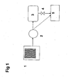
- FIG 1 schematically shows a system according to the invention comprising a storage unit ( 1 ) containing an ammonia storage material, preferably being a compacted metal ammine salt shown as a hatched unit, which system is operated at a reduced pressure using a vacuum pump ( 2 ).
- the pump draws ammonia from the storage material and delivers ammonia into a buffer volume ( 3 ) and ammonia is subsequently delivered to a consumer ( 5 ) such as a process or an ammonia consuming unit which has a need of a supply of ammonia through a dosing valve ( 4 ).
- Ammonia can alternatively be delivered directly from the pump ( 2 ) to the consumer ( 5 ) as indicated by the dotted line.
- a storage unit ( 1 ) containing an ammonia storage material preferably being a compacted metal ammine salt shown as a hatched unit, is operated at a reduced pressure using a vacuum pump ( 2 ).
- the pump delivers ammonia into a buffer volume ( 3 ) and ammonia is subsequently delivered to a consumer ( 5 ) through a dosing valve (4).
- Ammonia can also be delivered directly from the pump ( 2 ) to the consumer ( 5 ).
- the entire dosing system is monitored and/or controlled by a controller ( 6 ).
- a storage unit ( 1 ) containing an ammonia storage material preferably being a compacted metal ammine salt shown as a hatched unit, is operated at a reduced pressure using a vacuum pump ( 2 ).
- the pump delivers ammonia into a buffer volume ( 3 ) and ammonia is subsequently delivered to a consumer ( 5 ) through a dosing valve ( 4 ).
- Ammonia can also be delivered directly from the pump ( 2 ) to the consumer ( 5 ).
- the entire dosing system is monitored and/or controlled by a controller ( 6 ).
- the heat which is necessary to maintain a given operating temperature, i.e.
- the heat can be provided by electrical heating or by heat produced in a separate process step or unit, e.g. an engine or a fuel cell.
- the heat compensating for ammonia desorption may also be provided by normal thermal equilibration between the container (1) and the surroundings.
- FIG 4 shows an embodiment of a device for controlled delivery of ammonia to the exhaust gas of a combustion process.
- a storage unit ( 1 ) containing an ammonia storage material preferably being a compacted metal ammine salt shown as a hatched unit, is operated at a reduced pressure using a vacuum pump ( 2 ).
- the pump delivers ammonia into a buffer volume ( 3 ) and ammonia is subsequently delivered, through a dosing valve ( 4 ), to a conduit carrying an exhaust gas ( 8 ) containing NO x form a mobile or stationary combustion process or engine, wherein the gas mixture is passed through a SCR (Selective Catalytic Reduction) DeNOx catalyst ( 9 ).
- SCR Selective Catalytic Reduction
- Ammonia can also be delivered directly from the pump ( 2 ) to the exhaust gas conduit ( 8 ).
- the entire dosing system is monitored and/or controlled by a controller ( 6 ).
- a heater ( 7 ) supplies heat which is necessary to maintain a given operating temperature, i.e. to compensate for the endothermic release of ammonia controlled by the vacuum pump ( 2 ), to the unit ( 1 ).
- the heat can be provided by electrical heating or in the form of waste heat from a separate process step, e.g. an engine or a combustion process. As indicated by the dotted arrow, it may also be provided from the exhaust gas ( 8 ) to the container ( 1 ).
- the heater (7) in figure 4 may be redundant if the operating temperature of the container (1) is close to the temperature of the surroundings.
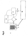
- FIG. 5 shows an embodiment of a device for controlled delivery of ammonia to an ammonia-fuelled fuel cell.
- a storage unit ( 1 ) containing an ammonia storage material preferably being a compacted metal ammine salt shown as a hatched unit, is operated at a reduced pressure using a vacuum pump ( 2 ).
- the pump delivers ammonia into a buffer volume ( 3 ) and ammonia is subsequently delivered to an ammonia-fuelled fuel cell ( 10 ) through a dosing valve ( 4 ).
- Ammonia can also be delivered directly from the pump ( 2 ) to the fuel cell ( 10 ).
- the entire dosing system is monitored and/or controlled by a controller ( 6 ).
- a heater ( 7 ) supplies heat which is necessary to maintain a given operating temperature, i.e. to compensate for the endothermic desorption of ammonia controlled by the vacuum pump ( 2 ), to the unit ( 1 ).
- the heat can be provided by electrical heating or in the form of waste heat from a separate process step, e.g. the fuel cell ( 8 ) as indicated by the dotted line.
- the heat compensating for ammonia desorption may also be provided by normal thermal equilibration between the container ( 1 ) and the surroundings.
- FIG. 6 shows an embodiment of a device according to the invention for controlled delivery of ammonia to a hydrogen-fuelled fuel cell through a reactor decomposing ammonia into nitrogen and hydrogen.
- a storage unit ( 1 ) containing an ammonia storage material, preferably being a compacted metal ammine salt shown as a hatched unit ( 1 ) is operated at a reduced pressure using a vacuum pump ( 2 ).
- the pump delivers ammonia into a buffer volume ( 3 ) and ammonia is delivered to an ammonia decomposition reactor ( 11 ) through a dosing valve ( 4 ).
- ammonia decomposition reactor ( 11 ) ammonia is decomposed into hydrogen and nitrogen, which is delivered to the hydrogen fuelled fuel cell ( 12 ).
- the entire dosing system is monitored and/or controlled by a controller ( 6 ).
- the heat ( 7 ) which is necessary to maintain a given operating temperature, i.e. to compensate for the endothermic desorption of ammonia controlled by the vacuum pump ( 2 ), is supplied to the unit ( 1 ) through a heater.
- the heat can be provided by electrical heating or by waste heat from a separate process step, e.g. the fuel cell ( 12 ) or the ammonia decomposition reactor ( 11 ) as indicated by the dotted lines.
- the heat compensating for ammonia desorption may also be provided by normal thermal equilibration between the container ( 1 ) and the surroundings.
- Figure 7 shows another embodiment of a device according to the invention for controlled delivery of ammonia to a hydrogen-fuelled fuel cell through a reactor decomposing ammonia into nitrogen and hydrogen.
- a storage unit ( 1 ) containing an ammonia storage material, preferably being a compacted metal ammine salt, is operated at a reduced pressure using a vacuum pump ( 2 ).
- the pump withdraws ammonia from the storage unit ( 1 ) through an ammonia decomposition reactor ( 11 ) and delivers hydrogen and nitrogen into a buffer volume ( 3 ), and hydrogen is subsequently delivered to the hydrogen-fuelled fuel cell ( 12 ) through a dosing valve ( 4 ).
- Hydrogen - generated in the reactor ( 11 ) - can alternatively be delivered directly from the pump ( 2 ) to the fuel cell ( 12 ) as indicated by the dotted line.
- the entire dosing system is monitored and/or controlled by a controller ( 6 ).
- a heater ( 7 ) supplied heat which is necessary to maintain a given operating temperature, i.e. to compensate for the endothermic release of ammonia controlled by the vacuum pump ( 2 ), to the unit ( 1 ).
- the heat can be provided by electrical heating or in the form of waste heat from a separate process step, e.g. the fuel cell ( 12 ).
- the heat compensating for ammonia desorption may also be provided by normal thermal equilibration between the container (1) and the surroundings.
- the advantage of the embodiment shown in figure 7 as compared to the embodiment shown in figure 6 is that a low pressure in both the storage delivery unit (1) and the decomposition reactor ( 9 ) during operation is advantageous for the equilibrium-limited decomposition of ammonia.
Landscapes
- Engineering & Computer Science (AREA)
- Chemical & Material Sciences (AREA)
- Chemical Kinetics & Catalysis (AREA)
- Environmental & Geological Engineering (AREA)
- Health & Medical Sciences (AREA)
- Combustion & Propulsion (AREA)
- Oil, Petroleum & Natural Gas (AREA)
- Biomedical Technology (AREA)
- General Chemical & Material Sciences (AREA)
- Organic Chemistry (AREA)
- Analytical Chemistry (AREA)
- Mechanical Engineering (AREA)
- General Engineering & Computer Science (AREA)
- Inorganic Chemistry (AREA)
- Toxicology (AREA)
- Exhaust Gas After Treatment (AREA)
- Treating Waste Gases (AREA)
- Solid-Sorbent Or Filter-Aiding Compositions (AREA)
- Filling Or Discharging Of Gas Storage Vessels (AREA)
Claims (18)
- Verfahren zur gesteuerten Bereitstellung von Ammoniak mit Hilfe von Vakuum, wobei das Verfahren die Schritte umfasst:(a) Bereitstellen eines Behälters (1);(b) Anordnen eines festen Metallammin-Salzes, das absorbiertes Ammoniak enthält und Ammoniak durch Binden von Ammoniak mittels Absorption bzw. erzwungenes Desorbieren von Ammoniak durch Verringerung des Drucks speichern/liefern kann, in den Behälter (1); und(c) Bewirken der Freisetzung von Ammoniak durch Desorption unter Verwendung einer Vakuumpumpe (2), um einen Ammoniak-Gasphasendruck in dem Behälter (1) zu erreichen, der unterhalb des entsprechenden thermodynamischen Ammoniak-Gleichgewichtsdrucks bei der Betriebstemperatur des Behälters (1) liegt,gekennzeichnet durch einen beliebigen der Schritte:Verwenden des freigesetzten Ammoniak bei der selektiven katalytischen Reduktion von NOx (9) in Abgasen (8) aus Verbrennungsprozessen oderEinspeisen des freigesetzten Ammoniaks in eine mit Ammoniak betriebene Brennstoffzelle als Brennstoff oder in einen Ammoniak-Zersetzungsreaktor (11), in dem Ammoniak in Stickstoff und Wasserstoff zersetzt wird und zumindest der Wasserstoff in eine mit Wasserstoff betriebene Brennstoffzelle (10, 12) als Brennstoff eingespeist wird.
- Verfahren nach Anspruch 1, bei dem das ammoniakhaltige Metallammin-Salz mit Ammoniak gesättigt ist.
- Verfahren nach Anspruch 1 oder 2, bei dem die Kühlwirkung des Ammoniak-Desorptionsprozesses durch Bereitstellung von Wärme für den Inhalt des Behälters (1) ausgeglichen wird.
- Verfahren nach irgendeinem der Ansprüche 1 - 3, bei dem der Temperaturabfall des Metallammin-Salzes, der durch den Ammoniak-Desorptionsprozess verursacht wird, durch Bereitstellung von Wärme aus einer elektrischen Widerstandsheizung (7) oder Wärme aus einem chemischen Prozess ausgeglichen wird.
- Verfahren nach irgendeinem der Ansprüche 1 - 3, bei dem der Temperaturabfall des Metallammin-Salzes, der durch den Ammoniak-Desorptionsprozess verursacht wird, durch Bereitstellung von Wärme in Form von Abwärme aus einem Abgas aus einem Verbrennungsprozess ausgeglichen wird.
- Verfahren nach Anspruch 5, bei dem der Temperaturabfall des Metallammin-Salzes, der durch den Ammoniak-Desorptionsprozess verursacht wird, durch Bereitstellung von Wärme aus dem Abgas einer Automobileinheit, die mittels Benzin, Diesel oder anderer Kohlenwasserstoff-Treibstoffe, wie Ethanol, oder synthetischem Brennstoff, wie Ammoniak oder Wasserstoff, betrieben wird, ausgeglichen wird.
- Verfahren nach Anspruch 1, wobei das Metallammin-Salz ein Salz der allgemeinen Formel: Ma(NH3)nXz ist, in der M für ein oder mehrere Kationen steht, die aus Alkalimetallen, wie Li, Na, K oder Cs, Erdalkalimetallen, wie Mg, Ca oder Sr, und/oder Übergangsmetallen, wie V, Cr, Mn, Fe, Co, Ni, Cu oder Zn, oder deren Kombinationen, wie NaAl, KAl, K2Zn, CsCu oder K2Fe, ausgewählt ist, X für ein oder mehrere Anionen steht, die aus Fluorid-, Chlorid-, Bromid-, lodid-, Nitrat-, Thiocyanat-, Sulfat-, Molybdat- und Phosphat-Ionen ausgewählt sind, a die Zahl der Kationen pro Salzmolekül ist, z die Zahl der Anionen pro Salzmolekül ist, und n die Koordinationszahl von 2 bis 12 ist.
- Verfahren nach Anspruch 7, bei dem das ionische Salz MgCl2, CaCl2, SrCl2 oder deren Mischungen ist.
- Verfahren nach irgendeinem der Ansprüche 1 - 9, bei dem das gesättigte ammoniakhaltige Metallamin-Salz in fester Form zu einem bzw. einer dichten Block, Stab, Zylinder, Ring oder Einheit mit Kanten, wie einem Würfel, mit einer Dichte über 70 % der theoretischen maximalen Gerüstdichte des gesättigten festen Metallammin-Salzes kompaktiert vorliegt, bevor es in den Behälter gegeben wird.
- Verfahren nach irgendeinem der Ansprüche 1 - 9, bei dem die Freisetzungsgeschwindigkeit von Ammoniak durch das eingestellte Vakuumniveau innerhalb des Behälters bestimmt wird, welches wiederum durch die Vakuumpumpe gesteuert wird.
- Verfahren nach irgendeinem der Ansprüche 1 - 10, bei dem die Zufuhr von Ammoniak weiter durch Reduktionsventile, Durchflussregler, Ventile oder eine ähnliche Art von Ausrüstung gesteuert wird.
- Verfahren nach Anspruch 1, bei dem das freigesetzte Ammoniak in einer selektiven katalytischen Reduktion von NOx (9) in Abgasen (8) aus Verbrennungsprozessen in stationären und mobilen Verbrennungsmotoren, welche mit Diesel, Benzin, Naturgas oder irgendwelchen anderen fossilen Brennstoffen oder mit Methanol, Ethanol, Wasserstoff, Methan, Ethan oder irgendwelchen anderen bio- oder synthetischen Brennstoffen, wie Ammoniak und Wasserstoff, betrieben werden, oder in stationären oder mobilen Kraftwerken, die mit Kohle, Naturgas, Öl oder irgendwelchen anderen fossilen Brennstoffen betrieben werden, verwendet wird.
- Vorrichtung zur Bereitstellung von Ammoniak gemäß dem Verfahren nach Anspruch 1 für die selektive katalytische Reduktion von NOx (9) in einem sauerstoffhaltigen Abgas eines Verbrennungsmotors oder eines Verbrennungsprozesses durch Verwendung von gasförmigem Ammoniak und einem Reduktionskatalysator, wobei die Vorrichtung umfasst:(a) einen Behälter (1) mit einem festen Metallammin-Salz, das absorbiertes Ammoniak enthält und Ammoniak durch Binden von Ammoniak mittels Absorption bzw. erzwungenes Desorbieren von Ammoniak durch Verringerung des Drucks speichern/liefern kann;(b) eine Vakuumpumpe (2) zur Erzeugung eines verringerten Drucks von Gasphasen-Ammoniak in dem Behälter, welcher unterhalb des entsprechenden Ammoniak-Gleichgewichtdrucks des Festkörpers bei der Betriebstemperatur des Behälters (1) liegt, wodurch Ammoniakfreisetzung mittels Desorption bewirkt wird,(c) fakultative Mittel (7) zum Heizen des Inhalts des Behälters, um den Temperaturabfall zu kompensieren, der durch den Ammoniak-Desorptionsprozess verursacht wird, wodurch eine gewünschte Betriebstemperatur beibehalten wird;
dadurch gekennzeichnet, dass die Vorrichtung weiter umfasst:(d) Mittel (4) zum Einführen von gasförmigem Ammoniak aus dem Behälter (1) in ein Abgas (8);(e) einen Katalysator zur Reduktion von NOx (9) durch Reaktion mit dem zudosierten Ammoniak und(f) Mittel (6) zum Steuern der Ammoniakmenge, die in die Abgasleitung(f1) eines Motors in Abhängigkeit von den Betriebsbedingungen des Motors und zum Erzielen eines optimalen Verhältnisses zwischen NOx und Ammoniak, um eine hohe NOx-Umwandlung zu erzielen, während ein Ammoniakauslecken aus dem Gas nach dem Katalysator minimiert wird, oder(f2) von stationären oder mobilen Kraftwerken, die Elektrizität erzeugen, eingeführt wird. - Vorrichtung nach Anspruch 13 zur Verwendung zur Reduktion von NOx (9) gemäß dem Verfahren nach Anspruch 1, wobei der Motor in Automobilen, Lastwagen, Zügen, Schiffen oder irgendeiner anderen motorisierten Maschine vorliegt.
- Verwendung einer Vakuumpumpe (2) zur Durchführung des Verfahrens nach Anspruch 1.
- Verwendung nach Anspruch 15, bei der Wärme für den Speicherbehälter (1) bereitgestellt wird, um den Temperaturabfall zu kompensieren, der durch den Ammoniak-Desorptionsprozess verursacht wird, wodurch der Behälter (1) bei einer gewünschten Betriebstemperatur gehalten wird.
- Verwendung nach Anspruch 15 oder 16, bei der das freigesetzte Ammoniak als Brennstoff in einer mit Ammoniak betriebenen Brennstoffzelle (10, 12) verwendet wird.
- Verwendung nach Anspruch 15 oder 16, bei der das freigesetzte Ammoniak in einen Ammoniak-Zersetzungsreaktor (11) eingespeist wird, in dem das Ammoniak in Stickstoff und Wasserstoff zersetzt wird, und zumindest der Wasserstoff als Brennstoff in einer mit Wasserstoff betriebenen Brennstoffzelle (10, 12) verwendet wird.
Applications Claiming Priority (2)
| Application Number | Priority Date | Filing Date | Title |
|---|---|---|---|
| DKPA200500967 | 2005-06-29 | ||
| PCT/DK2006/000385 WO2007000170A1 (en) | 2005-06-29 | 2006-06-29 | Method and device for safe and controlled delivery of ammonia from a solid ammonia storage medium |
Publications (2)
| Publication Number | Publication Date |
|---|---|
| EP1901831A1 EP1901831A1 (de) | 2008-03-26 |
| EP1901831B1 true EP1901831B1 (de) | 2012-12-19 |
Family
ID=36783932
Family Applications (1)
| Application Number | Title | Priority Date | Filing Date |
|---|---|---|---|
| EP20060753322 Not-in-force EP1901831B1 (de) | 2005-06-29 | 2006-06-29 | Verfahren und vorrichtung zur sicheren und kontrollierten zufuhr von ammoniak aus einem festen ammoniakspeichermedium |
Country Status (4)
| Country | Link |
|---|---|
| US (1) | US20100293927A1 (de) |
| EP (1) | EP1901831B1 (de) |
| JP (1) | JP2008546968A (de) |
| WO (1) | WO2007000170A1 (de) |
Families Citing this family (60)
| Publication number | Priority date | Publication date | Assignee | Title |
|---|---|---|---|---|
| DK1692113T3 (en) | 2003-11-14 | 2018-01-08 | Lorus Therapeutics Inc | ARYLIMIDAZOLES AND USE THEREOF AS ANTICANCES |
| CN101248072B (zh) | 2005-05-25 | 2013-01-23 | 劳洛斯治疗公司 | 2-吲哚基咪唑并[4,5-d]菲咯啉衍生物及其在癌症治疗中的用途 |
| DE102006032454A1 (de) * | 2006-07-13 | 2008-01-17 | Arvinmeritor Emissions Technologies Gmbh | Abgasanlage für eine Verbrennungskraftmaschine |
| DE102007004602B4 (de) * | 2007-01-30 | 2009-05-28 | Continental Automotive Gmbh | Heizvorrichtung zum Erhitzen eines Speichers für ein Komplexsalz |
| DE102007014846B4 (de) * | 2007-03-28 | 2012-09-27 | Robert Bosch Gmbh | Thermochemischer Wärmespeicher, Heizsystem mit einem thermochemischen Wärmespeicher und Verwendung des Heizsystems |
| ATE489158T1 (de) * | 2007-03-30 | 2010-12-15 | Amminex As | System zur lagerung von ammoniak in und zu seiner abgabe aus einem lagerungsmaterial und verfahren zur lagerung und abgabe von ammoniak |
| US8034499B2 (en) * | 2007-04-05 | 2011-10-11 | Delphi Technologies, Inc. | Energy conversion device including a solid oxide fuel cell fueled by ammonia |
| ATE523238T1 (de) * | 2007-05-16 | 2011-09-15 | Amminex As | Verfahren und vorrichtung zur sicheren lagerung und verwendung von flüchtigen ammoniaklagermaterialien |
| DE102008001709A1 (de) * | 2008-05-13 | 2009-11-19 | Robert Bosch Gmbh | Vorrichtung, System und Verfahren zur Bereitstellung eines Reduktionsmittel für ein System zur selektiven katalytischen Reduktion von Stickoxiden |
| DE102008002281A1 (de) * | 2008-06-06 | 2009-12-10 | Robert Bosch Gmbh | Verfahren zur Beladung eines Gasspeichers |
| US11634815B2 (en) * | 2008-07-03 | 2023-04-25 | Rasirc, Inc. | Method, system, and device for storage and delivery of process gas from a substrate |
| EP2175246B1 (de) | 2008-10-09 | 2017-07-19 | Sensirion AG | Verfahren zur Messung eines Parameters einer Fluidzusammensetzung mithilfe eines Flusssensors |
| EP2204555B1 (de) | 2009-01-02 | 2011-08-03 | Sensirion AG | Ammoniakspeichersystem |
| EP2236784B1 (de) | 2009-03-18 | 2012-06-06 | Amminex A/S | Verbessertes Verfahren zum Lagern und Zuführen von Ammoniak aus festen gelagerten Materialien unter Verwendung einer Vakuumpumpe |
| EP2419381A1 (de) | 2009-04-15 | 2012-02-22 | Amminex A/S | Herstellung von gesättigten ammoniakspeichermaterialien |
| EP2241535B1 (de) | 2009-04-15 | 2013-07-10 | Amminex Emissions Technology A/S | Herstellung von Speichermaterialien für gesättigten Ammoniak |
| US8084008B2 (en) | 2009-04-16 | 2011-12-27 | Amminex A/S | Production of saturated ammonia storage materials |
| DE102009030405A1 (de) * | 2009-06-25 | 2010-12-30 | Bayerische Motoren Werke Aktiengesellschaft | Einrichtung zum Speichern von Ammoniak und Verfahren zum Einlagern von Ammoniak in einer Speichereinrichtung |
| EP2301650B1 (de) | 2009-09-24 | 2016-11-02 | Haldor Topsøe A/S | Verfahren und katalysatorsystem für scr von nox |
| US8215331B2 (en) * | 2009-11-13 | 2012-07-10 | Quantum Fuel Systems Technologies Worldwide, Inc. | Leak mitigation for pressurized bi-directional systems |
| DE102009047663A1 (de) | 2009-12-08 | 2011-06-09 | Robert Bosch Gmbh | Verfahren und Vorrichtung zur Nachladung von NOx-Reduktionsmittel-Speicherbehältern |
| JP5000732B2 (ja) | 2010-02-06 | 2012-08-15 | 本田技研工業株式会社 | 内燃機関の排気浄化装置 |
| JP5000731B2 (ja) | 2010-02-06 | 2012-08-15 | 本田技研工業株式会社 | 内燃機関の排気浄化装置 |
| EP2366448B1 (de) * | 2010-03-16 | 2016-07-27 | Amminex Emissions Technology A/S | Verfahren und Vorrichtung zur kontrollierten Dosierung eines Gases mit veränderlichem Zuströmdruck |
| FR2957630A1 (fr) * | 2010-03-19 | 2011-09-23 | Peugeot Citroen Automobiles Sa | Dispositif d'injection dans une ligne d'echappement d'un agent reducteur gazeux |
| US20150047992A1 (en) * | 2010-03-29 | 2015-02-19 | International Engine Intellectual Property Company, Llc | Ammonia dosing cartridge and method |
| CN101880026B (zh) * | 2010-06-03 | 2011-12-21 | 苏州苏净保护气氛有限公司 | 一种氨分解装置 |
| FR2962122B1 (fr) * | 2010-07-01 | 2012-08-10 | Faurecia Sys Echappement | Procede de fabrication d'une cartouche de stockage d'ammoniaque, notamment pour systeme d'echappement de gaz de vehicule automobile |
| EP2412946B1 (de) * | 2010-07-28 | 2015-08-19 | Aaqius & Aaqius S.A. | Verfahren zur Reduzierung der Menge an Stickoxiden (NOx) in Abgasen von Kraftfahrzeugen |
| JP5625627B2 (ja) * | 2010-08-30 | 2014-11-19 | 株式会社豊田中央研究所 | アンモニア吸蔵装置および選択的触媒還元システム |
| EP2444614B1 (de) * | 2010-10-25 | 2013-08-14 | Aaqius & Aaqius S.A. | System zur Verringerung der Stickoxidmenge in den Abgasen eines Kraftfahrzeugs |
| WO2012134516A1 (en) * | 2011-03-30 | 2012-10-04 | International Engine Intellectual Property Company, Llc | Status indicator for ammonia cartridge |
| FR2974389B1 (fr) | 2011-04-20 | 2013-05-17 | Peugeot Citroen Automobiles Sa | Procede de detection d'un changement de cartouche de reducteur dans un systeme scr, ligne d'echappement et vehicule |
| KR20130024079A (ko) * | 2011-08-30 | 2013-03-08 | 현대자동차주식회사 | 고체 scr 시스템 및 이를 이용한 고체상의 환원제 가열 방법 |
| JP5630411B2 (ja) * | 2011-09-26 | 2014-11-26 | 株式会社豊田中央研究所 | 熱回収式加熱装置 |
| WO2013072982A1 (ja) * | 2011-11-14 | 2013-05-23 | トヨタ自動車株式会社 | 内燃機関の排気浄化装置 |
| US9863725B1 (en) * | 2012-02-29 | 2018-01-09 | The United States Of America As Represented By The Secretary Of The Air Force | Systems and methods for thermal management through use of ammonium carbamate |
| US9381466B2 (en) | 2012-04-03 | 2016-07-05 | Korea Institute Of Machinery & Materials | Exhaust gas purification system |
| EP2695858B1 (de) * | 2012-08-09 | 2015-09-16 | Aaqius & Aaqius S.A. | System zur Lagerung und Abgabe von gasförmigem Ammoniak |
| FR2995629B1 (fr) * | 2012-09-14 | 2014-10-17 | Faurecia Sys Echappement | Dispositif de stockage d'ammoniac et ligne d'echappement equipee d'un tel dispositif |
| SE537640C2 (sv) * | 2013-03-07 | 2015-09-01 | Scania Cv Ab | Förfarande vid ett SCR-system och ett SCR-system |
| WO2014153464A2 (en) | 2013-03-20 | 2014-09-25 | Lorus Therapeutics Inc. | 2-substituted imidazo[4,5-d]phenanthroline derivatives and their use in the treatment of cancer |
| WO2014169935A1 (en) | 2013-04-15 | 2014-10-23 | Haldor Topsøe A/S | Process and catalyst system for selective reduction of nitrogen oxides |
| CN105764511B (zh) | 2013-10-04 | 2019-01-11 | 艾普托斯生物科学公司 | 用于治疗癌症的组合物和方法 |
| CN103541794B (zh) * | 2013-10-30 | 2016-03-02 | 中国第一汽车股份有限公司 | 固体储氨系统的循环冲氨方法 |
| US9914645B2 (en) | 2013-11-07 | 2018-03-13 | Regents Of The University Of Minnesota | Process for making ammonia |
| JP5568190B1 (ja) * | 2014-03-03 | 2014-08-06 | 株式会社ベスト測器 | 排ガス浄化システムの性能を評価する装置 |
| JP6369129B2 (ja) * | 2014-05-23 | 2018-08-08 | 株式会社豊田中央研究所 | アンモニア吸蔵放出装置 |
| EP3088231A1 (de) * | 2015-04-28 | 2016-11-02 | Inergy Automotive Systems Research (Société Anonyme) | Ammoniakvorläufer-nachfüllvorrichtung |
| JP6623030B2 (ja) * | 2015-10-28 | 2019-12-18 | 株式会社Kri | 固体酸化物形燃料電池システム |
| JP6623031B2 (ja) * | 2015-10-28 | 2019-12-18 | 株式会社Kri | 固体酸化物形燃料電池システムの運転方法 |
| JP6623091B2 (ja) * | 2016-03-18 | 2019-12-18 | 株式会社Kri | アンモニア貯蔵供給装置及びアンモニア燃料タンク |
| CN106593592A (zh) * | 2017-01-18 | 2017-04-26 | 吉林省众鑫汽车装备有限公司 | 一种固体氨储氨系统及具有该系统的车辆 |
| EP3351761A1 (de) | 2017-01-19 | 2018-07-25 | Backer BHV AB | Ammoniakspeichertank und verwendung davon |
| CN110770175B (zh) * | 2017-06-16 | 2022-04-19 | 高桥金属株式会社 | 吸附方法 |
| CN111417395A (zh) | 2017-10-30 | 2020-07-14 | 艾普托斯生物科学公司 | 用于治疗癌症的芳基咪唑 |
| EP3710126A4 (de) * | 2017-11-17 | 2021-08-11 | Rasirc, Inc. | Verfahren, system und vorrichtung zur speicherung und abgabe von prozessgas von einem substrat |
| US10378408B1 (en) * | 2018-03-26 | 2019-08-13 | Caterpillar Inc. | Ammonia generation and storage systems and methods |
| EP3657146A1 (de) * | 2018-11-23 | 2020-05-27 | Amminex Emissions Technology A/S | Design eines korrosionsbeständigen drucksensors unter verwendung eines kontrollierten leckprinzips |
| US11732628B1 (en) * | 2020-08-12 | 2023-08-22 | Old World Industries, Llc | Diesel exhaust fluid |
Family Cites Families (13)
| Publication number | Priority date | Publication date | Assignee | Title |
|---|---|---|---|---|
| JP2675321B2 (ja) * | 1987-01-27 | 1997-11-12 | 株式会社日本触媒 | ディーゼルエンジン排ガス中の窒素酸化物除去方法 |
| US5165247A (en) * | 1991-02-11 | 1992-11-24 | Rocky Research | Refrigerant recycling system |
| US6244056B1 (en) * | 1995-09-20 | 2001-06-12 | Sun Microsystems, Inc. | Controlled production of ammonia and other gases |
| US5711147A (en) * | 1996-08-19 | 1998-01-27 | The Regents Of The University Of California | Plasma-assisted catalytic reduction system |
| US5809775A (en) * | 1997-04-02 | 1998-09-22 | Clean Diesel Technologies, Inc. | Reducing NOx emissions from an engine by selective catalytic reduction utilizing solid reagents |
| DE19728343C5 (de) * | 1997-07-03 | 2013-02-21 | Robert Bosch Gmbh | Verfahren und Vorrichtung zur selektiven katalytischen NOx-Reduktion |
| JP2000117100A (ja) * | 1998-08-13 | 2000-04-25 | Osaka Gas Co Ltd | ガス貯蔵性有機金属錯体、その製造方法およびガス貯蔵装置 |
| US6266955B1 (en) * | 1999-08-20 | 2001-07-31 | Caterpillar Inc. | Diagnostic system for an emissions control on an engine |
| US20040020188A1 (en) * | 2002-08-05 | 2004-02-05 | Kramer Dennis A. | Method and apparatus for generating pressurized air by use of reformate gas from a fuel reformer |
| GB0314463D0 (en) * | 2003-06-23 | 2003-07-23 | Eminox Ltd | Method of calibrating reductant injection in a SCR system |
| JP2005021743A (ja) * | 2003-06-30 | 2005-01-27 | Fuji Photo Film Co Ltd | 写真廃液の処理方法 |
| AT412845B (de) * | 2003-07-14 | 2005-08-25 | Alpps Fuel Cell Systems Gmbh | Abgasnachbehandlungssystem zur reduzierung der nox-emissionen von wärmekraftmaschinen mittels aus treibstoff erzeugtem reduktionsmittel |
| JP2008508186A (ja) * | 2004-08-03 | 2008-03-21 | アムミネクス・アー/エス | 固体アンモニア貯蔵及び移送材料 |
-
2006
- 2006-06-29 JP JP2008518633A patent/JP2008546968A/ja active Pending
- 2006-06-29 WO PCT/DK2006/000385 patent/WO2007000170A1/en not_active Ceased
- 2006-06-29 EP EP20060753322 patent/EP1901831B1/de not_active Not-in-force
- 2006-06-29 US US11/993,731 patent/US20100293927A1/en not_active Abandoned
Also Published As
| Publication number | Publication date |
|---|---|
| WO2007000170A1 (en) | 2007-01-04 |
| JP2008546968A (ja) | 2008-12-25 |
| EP1901831A1 (de) | 2008-03-26 |
| US20100293927A1 (en) | 2010-11-25 |
Similar Documents
| Publication | Publication Date | Title |
|---|---|---|
| US20100293927A1 (en) | Method and device for safe and controlled delivery of ammonia from a solid ammonia storage medium | |
| US8088201B2 (en) | Method and device for safe storage and use of volatile ammonia storage materials | |
| US9889403B2 (en) | Solid ammonia storage and delivery material | |
| CN101541401B (zh) | 使用输送单元的原位再饱和存储和输送氨的方法和设备 | |
| JP5305661B2 (ja) | アンモニアの高密度貯蔵 | |
| EP1992397B1 (de) | Verfahren und Vorrichtung zur sicheren Lagerung und Verwendung von flüchtigen Ammoniaklagermaterialien | |
| US6387336B2 (en) | Method and device for selective catalytic NOx reduction | |
| US8578702B2 (en) | Method of storing and delivering ammonia and the use of electromagnetic radiation for desorption of ammonia from a chemical complex | |
| CN101128394B (zh) | 氨的高密度存储 | |
| EP2051798B1 (de) | Verfahren und vorrichtung zur speicherung und lieferung von ammoniak aus einem festen ammoniakspeichermedium | |
| JP2020503467A (ja) | カルバミン酸アンモニウムの生成および窒素酸化物の還元 | |
| US9400064B2 (en) | Method and device for ammonia storage and delivery using in-situ re-saturation of a delivery unit | |
| CN104487156A (zh) | 用于净化燃烧发动机的排放气体的方法和系统 | |
| EP2109493A1 (de) | Verfahren und vorrichtung zur sicheren aufbewahrung und zufuhr von ammoniak und verwendung von speichermaterialien | |
| CN101076495B (zh) | 存储和输送氨的固体材料 | |
| JP2010513004A (ja) | 供給ユニットの現場再飽和を利用するアンモニアの貯蔵および供給のための方法ならびにデバイス | |
| KR101985730B1 (ko) | 암모니아 발생 및 방출 장치 |
Legal Events
| Date | Code | Title | Description |
|---|---|---|---|
| PUAI | Public reference made under article 153(3) epc to a published international application that has entered the european phase |
Free format text: ORIGINAL CODE: 0009012 |
|
| 17P | Request for examination filed |
Effective date: 20071221 |
|
| AK | Designated contracting states |
Kind code of ref document: A1 Designated state(s): AT BE BG CH CY CZ DE DK EE ES FI FR GB GR HU IE IS IT LI LT LU LV MC NL PL PT RO SE SI SK TR |
|
| DAX | Request for extension of the european patent (deleted) | ||
| RIN1 | Information on inventor provided before grant (corrected) |
Inventor name: N0RSKOV, JENS K. Inventor name: JOHANNESSEN, TUE Inventor name: CHRISTENSEN, GLAUS, HVID Inventor name: SORENSEN,RASMUS,ZINK Inventor name: QUAADE, ULRICH |
|
| DAX | Request for extension of the european patent (deleted) | ||
| RAP1 | Party data changed (applicant data changed or rights of an application transferred) |
Owner name: AMMINEX A/S |
|
| 17Q | First examination report despatched |
Effective date: 20100621 |
|
| REG | Reference to a national code |
Ref country code: DE Ref legal event code: R079 Ref document number: 602006033708 Country of ref document: DE Free format text: PREVIOUS MAIN CLASS: B01D0053560000 Ipc: B01D0053790000 |
|
| GRAP | Despatch of communication of intention to grant a patent |
Free format text: ORIGINAL CODE: EPIDOSNIGR1 |
|
| RIC1 | Information provided on ipc code assigned before grant |
Ipc: C01C 1/00 20060101ALI20120208BHEP Ipc: B01D 53/86 20060101ALI20120208BHEP Ipc: B01D 53/79 20060101AFI20120208BHEP Ipc: B01D 53/94 20060101ALI20120208BHEP Ipc: F01N 5/02 20060101ALI20120208BHEP Ipc: F01N 3/20 20060101ALI20120208BHEP |
|
| GRAS | Grant fee paid |
Free format text: ORIGINAL CODE: EPIDOSNIGR3 |
|
| GRAA | (expected) grant |
Free format text: ORIGINAL CODE: 0009210 |
|
| AK | Designated contracting states |
Kind code of ref document: B1 Designated state(s): AT BE BG CH CY CZ DE DK EE ES FI FR GB GR HU IE IS IT LI LT LU LV MC NL PL PT RO SE SI SK TR |
|
| REG | Reference to a national code |
Ref country code: GB Ref legal event code: FG4D |
|
| REG | Reference to a national code |
Ref country code: CH Ref legal event code: EP |
|
| REG | Reference to a national code |
Ref country code: AT Ref legal event code: REF Ref document number: 589065 Country of ref document: AT Kind code of ref document: T Effective date: 20130115 |
|
| REG | Reference to a national code |
Ref country code: DE Ref legal event code: R096 Ref document number: 602006033708 Country of ref document: DE Effective date: 20130214 |
|
| RAP2 | Party data changed (patent owner data changed or rights of a patent transferred) |
Owner name: AMMINEX EMISSIONS TECHNOLOGY A/S |
|
| REG | Reference to a national code |
Ref country code: DE Ref legal event code: R082 Ref document number: 602006033708 Country of ref document: DE Representative=s name: SAMSON & PARTNER, PATENTANWAELTE, DE Effective date: 20130221 Ref country code: DE Ref legal event code: R081 Ref document number: 602006033708 Country of ref document: DE Owner name: AMMINEX EMISSIONS TECHNOLOGY A/S, DK Free format text: FORMER OWNER: AMMINEX A/S, SOEBORG, DK Effective date: 20130221 Ref country code: DE Ref legal event code: R082 Ref document number: 602006033708 Country of ref document: DE Representative=s name: SAMSON & PARTNER PATENTANWAELTE MBB, DE Effective date: 20130221 |
|
| PG25 | Lapsed in a contracting state [announced via postgrant information from national office to epo] |
Ref country code: FI Free format text: LAPSE BECAUSE OF FAILURE TO SUBMIT A TRANSLATION OF THE DESCRIPTION OR TO PAY THE FEE WITHIN THE PRESCRIBED TIME-LIMIT Effective date: 20121219 Ref country code: LT Free format text: LAPSE BECAUSE OF FAILURE TO SUBMIT A TRANSLATION OF THE DESCRIPTION OR TO PAY THE FEE WITHIN THE PRESCRIBED TIME-LIMIT Effective date: 20121219 Ref country code: ES Free format text: LAPSE BECAUSE OF FAILURE TO SUBMIT A TRANSLATION OF THE DESCRIPTION OR TO PAY THE FEE WITHIN THE PRESCRIBED TIME-LIMIT Effective date: 20130330 Ref country code: SE Free format text: LAPSE BECAUSE OF FAILURE TO SUBMIT A TRANSLATION OF THE DESCRIPTION OR TO PAY THE FEE WITHIN THE PRESCRIBED TIME-LIMIT Effective date: 20121219 |
|
| REG | Reference to a national code |
Ref country code: NL Ref legal event code: VDEP Effective date: 20121219 Ref country code: AT Ref legal event code: MK05 Ref document number: 589065 Country of ref document: AT Kind code of ref document: T Effective date: 20121219 |
|
| REG | Reference to a national code |
Ref country code: LT Ref legal event code: MG4D |
|
| PG25 | Lapsed in a contracting state [announced via postgrant information from national office to epo] |
Ref country code: SI Free format text: LAPSE BECAUSE OF FAILURE TO SUBMIT A TRANSLATION OF THE DESCRIPTION OR TO PAY THE FEE WITHIN THE PRESCRIBED TIME-LIMIT Effective date: 20121219 Ref country code: LV Free format text: LAPSE BECAUSE OF FAILURE TO SUBMIT A TRANSLATION OF THE DESCRIPTION OR TO PAY THE FEE WITHIN THE PRESCRIBED TIME-LIMIT Effective date: 20121219 Ref country code: GR Free format text: LAPSE BECAUSE OF FAILURE TO SUBMIT A TRANSLATION OF THE DESCRIPTION OR TO PAY THE FEE WITHIN THE PRESCRIBED TIME-LIMIT Effective date: 20130320 |
|
| PG25 | Lapsed in a contracting state [announced via postgrant information from national office to epo] |
Ref country code: BE Free format text: LAPSE BECAUSE OF FAILURE TO SUBMIT A TRANSLATION OF THE DESCRIPTION OR TO PAY THE FEE WITHIN THE PRESCRIBED TIME-LIMIT Effective date: 20121219 Ref country code: AT Free format text: LAPSE BECAUSE OF FAILURE TO SUBMIT A TRANSLATION OF THE DESCRIPTION OR TO PAY THE FEE WITHIN THE PRESCRIBED TIME-LIMIT Effective date: 20121219 Ref country code: EE Free format text: LAPSE BECAUSE OF FAILURE TO SUBMIT A TRANSLATION OF THE DESCRIPTION OR TO PAY THE FEE WITHIN THE PRESCRIBED TIME-LIMIT Effective date: 20121219 Ref country code: IS Free format text: LAPSE BECAUSE OF FAILURE TO SUBMIT A TRANSLATION OF THE DESCRIPTION OR TO PAY THE FEE WITHIN THE PRESCRIBED TIME-LIMIT Effective date: 20130419 Ref country code: BG Free format text: LAPSE BECAUSE OF FAILURE TO SUBMIT A TRANSLATION OF THE DESCRIPTION OR TO PAY THE FEE WITHIN THE PRESCRIBED TIME-LIMIT Effective date: 20130319 Ref country code: CZ Free format text: LAPSE BECAUSE OF FAILURE TO SUBMIT A TRANSLATION OF THE DESCRIPTION OR TO PAY THE FEE WITHIN THE PRESCRIBED TIME-LIMIT Effective date: 20121219 Ref country code: SK Free format text: LAPSE BECAUSE OF FAILURE TO SUBMIT A TRANSLATION OF THE DESCRIPTION OR TO PAY THE FEE WITHIN THE PRESCRIBED TIME-LIMIT Effective date: 20121219 |
|
| PG25 | Lapsed in a contracting state [announced via postgrant information from national office to epo] |
Ref country code: NL Free format text: LAPSE BECAUSE OF FAILURE TO SUBMIT A TRANSLATION OF THE DESCRIPTION OR TO PAY THE FEE WITHIN THE PRESCRIBED TIME-LIMIT Effective date: 20121219 Ref country code: PT Free format text: LAPSE BECAUSE OF FAILURE TO SUBMIT A TRANSLATION OF THE DESCRIPTION OR TO PAY THE FEE WITHIN THE PRESCRIBED TIME-LIMIT Effective date: 20130419 Ref country code: PL Free format text: LAPSE BECAUSE OF FAILURE TO SUBMIT A TRANSLATION OF THE DESCRIPTION OR TO PAY THE FEE WITHIN THE PRESCRIBED TIME-LIMIT Effective date: 20121219 Ref country code: RO Free format text: LAPSE BECAUSE OF FAILURE TO SUBMIT A TRANSLATION OF THE DESCRIPTION OR TO PAY THE FEE WITHIN THE PRESCRIBED TIME-LIMIT Effective date: 20121219 |
|
| PLBE | No opposition filed within time limit |
Free format text: ORIGINAL CODE: 0009261 |
|
| STAA | Information on the status of an ep patent application or granted ep patent |
Free format text: STATUS: NO OPPOSITION FILED WITHIN TIME LIMIT |
|
| PG25 | Lapsed in a contracting state [announced via postgrant information from national office to epo] |
Ref country code: DK Free format text: LAPSE BECAUSE OF FAILURE TO SUBMIT A TRANSLATION OF THE DESCRIPTION OR TO PAY THE FEE WITHIN THE PRESCRIBED TIME-LIMIT Effective date: 20121219 |
|
| 26N | No opposition filed |
Effective date: 20130920 |
|
| PG25 | Lapsed in a contracting state [announced via postgrant information from national office to epo] |
Ref country code: CY Free format text: LAPSE BECAUSE OF FAILURE TO SUBMIT A TRANSLATION OF THE DESCRIPTION OR TO PAY THE FEE WITHIN THE PRESCRIBED TIME-LIMIT Effective date: 20121219 |
|
| PG25 | Lapsed in a contracting state [announced via postgrant information from national office to epo] |
Ref country code: IT Free format text: LAPSE BECAUSE OF FAILURE TO SUBMIT A TRANSLATION OF THE DESCRIPTION OR TO PAY THE FEE WITHIN THE PRESCRIBED TIME-LIMIT Effective date: 20121219 |
|
| REG | Reference to a national code |
Ref country code: DE Ref legal event code: R097 Ref document number: 602006033708 Country of ref document: DE Effective date: 20130920 |
|
| PG25 | Lapsed in a contracting state [announced via postgrant information from national office to epo] |
Ref country code: MC Free format text: LAPSE BECAUSE OF FAILURE TO SUBMIT A TRANSLATION OF THE DESCRIPTION OR TO PAY THE FEE WITHIN THE PRESCRIBED TIME-LIMIT Effective date: 20121219 |
|
| REG | Reference to a national code |
Ref country code: CH Ref legal event code: PL |
|
| GBPC | Gb: european patent ceased through non-payment of renewal fee |
Effective date: 20130629 |
|
| REG | Reference to a national code |
Ref country code: IE Ref legal event code: MM4A |
|
| REG | Reference to a national code |
Ref country code: FR Ref legal event code: ST Effective date: 20140228 |
|
| PG25 | Lapsed in a contracting state [announced via postgrant information from national office to epo] |
Ref country code: CH Free format text: LAPSE BECAUSE OF NON-PAYMENT OF DUE FEES Effective date: 20130630 Ref country code: GB Free format text: LAPSE BECAUSE OF NON-PAYMENT OF DUE FEES Effective date: 20130629 Ref country code: IE Free format text: LAPSE BECAUSE OF NON-PAYMENT OF DUE FEES Effective date: 20130629 Ref country code: LI Free format text: LAPSE BECAUSE OF NON-PAYMENT OF DUE FEES Effective date: 20130630 |
|
| PG25 | Lapsed in a contracting state [announced via postgrant information from national office to epo] |
Ref country code: FR Free format text: LAPSE BECAUSE OF NON-PAYMENT OF DUE FEES Effective date: 20130701 |
|
| PG25 | Lapsed in a contracting state [announced via postgrant information from national office to epo] |
Ref country code: TR Free format text: LAPSE BECAUSE OF FAILURE TO SUBMIT A TRANSLATION OF THE DESCRIPTION OR TO PAY THE FEE WITHIN THE PRESCRIBED TIME-LIMIT Effective date: 20121219 |
|
| PG25 | Lapsed in a contracting state [announced via postgrant information from national office to epo] |
Ref country code: HU Free format text: LAPSE BECAUSE OF FAILURE TO SUBMIT A TRANSLATION OF THE DESCRIPTION OR TO PAY THE FEE WITHIN THE PRESCRIBED TIME-LIMIT; INVALID AB INITIO Effective date: 20060629 Ref country code: LU Free format text: LAPSE BECAUSE OF NON-PAYMENT OF DUE FEES Effective date: 20130629 |
|
| PGFP | Annual fee paid to national office [announced via postgrant information from national office to epo] |
Ref country code: DE Payment date: 20180831 Year of fee payment: 13 |
|
| REG | Reference to a national code |
Ref country code: DE Ref legal event code: R119 Ref document number: 602006033708 Country of ref document: DE |
|
| PG25 | Lapsed in a contracting state [announced via postgrant information from national office to epo] |
Ref country code: DE Free format text: LAPSE BECAUSE OF NON-PAYMENT OF DUE FEES Effective date: 20200101 |