EP1902349B1 - Inverseur a etage unique et procede de controle connexe pour convertisseurs de puissance a partir de sources d'energie, en particulier photovoltaiques - Google Patents
Inverseur a etage unique et procede de controle connexe pour convertisseurs de puissance a partir de sources d'energie, en particulier photovoltaiques Download PDFInfo
- Publication number
- EP1902349B1 EP1902349B1 EP05823480A EP05823480A EP1902349B1 EP 1902349 B1 EP1902349 B1 EP 1902349B1 EP 05823480 A EP05823480 A EP 05823480A EP 05823480 A EP05823480 A EP 05823480A EP 1902349 B1 EP1902349 B1 EP 1902349B1
- Authority
- EP
- European Patent Office
- Prior art keywords
- voltage
- max
- output
- grid
- power
- Prior art date
- Legal status (The legal status is an assumption and is not a legal conclusion. Google has not performed a legal analysis and makes no representation as to the accuracy of the status listed.)
- Expired - Lifetime
Links
Images





Classifications
-
- G—PHYSICS
- G05—CONTROLLING; REGULATING
- G05F—SYSTEMS FOR REGULATING ELECTRIC OR MAGNETIC VARIABLES
- G05F1/00—Automatic systems in which deviations of an electric quantity from one or more predetermined values are detected at the output of the system and fed back to a device within the system to restore the detected quantity to its predetermined value or values, i.e. retroactive systems
- G05F1/66—Regulating electric power
- G05F1/67—Regulating electric power to the maximum power available from a generator, e.g. from solar cell
-
- Y—GENERAL TAGGING OF NEW TECHNOLOGICAL DEVELOPMENTS; GENERAL TAGGING OF CROSS-SECTIONAL TECHNOLOGIES SPANNING OVER SEVERAL SECTIONS OF THE IPC; TECHNICAL SUBJECTS COVERED BY FORMER USPC CROSS-REFERENCE ART COLLECTIONS [XRACs] AND DIGESTS
- Y02—TECHNOLOGIES OR APPLICATIONS FOR MITIGATION OR ADAPTATION AGAINST CLIMATE CHANGE
- Y02E—REDUCTION OF GREENHOUSE GAS [GHG] EMISSIONS, RELATED TO ENERGY GENERATION, TRANSMISSION OR DISTRIBUTION
- Y02E10/00—Energy generation through renewable energy sources
- Y02E10/50—Photovoltaic [PV] energy
- Y02E10/56—Power conversion systems, e.g. maximum power point trackers
-
- Y—GENERAL TAGGING OF NEW TECHNOLOGICAL DEVELOPMENTS; GENERAL TAGGING OF CROSS-SECTIONAL TECHNOLOGIES SPANNING OVER SEVERAL SECTIONS OF THE IPC; TECHNICAL SUBJECTS COVERED BY FORMER USPC CROSS-REFERENCE ART COLLECTIONS [XRACs] AND DIGESTS
- Y10—TECHNICAL SUBJECTS COVERED BY FORMER USPC
- Y10S—TECHNICAL SUBJECTS COVERED BY FORMER USPC CROSS-REFERENCE ART COLLECTIONS [XRACs] AND DIGESTS
- Y10S323/00—Electricity: power supply or regulation systems
- Y10S323/906—Solar cell systems
Definitions
- the present invention concerns a single stage inverter device for a power electronic converter, with alternate current output and direct current input (dc-ac), for energy sources, in particular renewable energy sources, preferably photovoltaic sources, based on the so called switching one-cycle control or OCC technique, with maximum power point tracking or MPPT that is static or possibly dynamically adaptive through Perturb&Observe or P&O technique, the device being simple, reliable, efficient, precise, and inexpensive, simultaneously optimising both the MPPT control and the output Power Factor or PF-out of the dc-ac converter, so as to possibly also achieve the real maximum power point tracking of the photovoltaic field through dynamic adaptation to the operation instant conditions of the photovoltaic field.
- dc-ac alternate current output and direct current input
- the present invention further concerns the related method of scaling the characteristic parameters of such inverter device and the related controlling method.
- single-phase power dc-ac converters for energy photovoltaic sources known as so-called "grid-connected" systems (connected to an alternate current electric energy distribution network), but it should be understood that the inverter device (and the related controlling method) according to the invention may be applied to both single-phase and multiphase converters for any energy source, in particular renewable, such as fuel cells, wind turbines, and other sources having a variable maximum power point, or more generally a maximum energy convenience point maximum energy convenience point, at the input, and a constrained PF-out at the output.
- renewable such as fuel cells, wind turbines, and other sources having a variable maximum power point, or more generally a maximum energy convenience point maximum energy convenience point, at the input, and a constrained PF-out at the output.
- the inverter device may be applied to converters for any energy source that is characterised by the existence of particular specific operation conditions which are deemed preferential, in relation to produced energy, energy efficiency, component stress degree, life, or any other evaluation factor may be defined for a specific source, and which conditions are variable, due to climatic or physical factors or factors of any nature, which are either controllable or uncontrollable, either predictable or unpredictable, and identifiable through a particular point of one of the source output electrical characteristic curves such as power-voltage, power-current, voltage-current, current-voltage, efficiency-voltage, efficiency-current or other ones similar thereto.
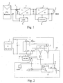
- the market presently offers several photovoltaic inverters, generally based on a double stage architecture, of the type shown in Figure 1 for a single-phase application, interposed between the photovoltaic source 1 and the ac electric energy distribution grid 2.
- Such architecture presents as main advantage some ease of design and implementation thanks to the separation of the two functionalities of MPPT and dc-ac conversion with PF-out control: the first one is achieved by the dc-dc converter 3, controlled by the maximum power point tracking MPPT module 4 connected to the output of the source 1, while the functionality of dc-ac conversion is achieved through the dc-ac converter 5, controlled by the module 6 connected to the input of the grid 2.
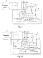
- the single stage inverter is controlled by a driving unit 8, that operates on the basis of values of certain electric quantities at input and output of the same converter, through the One-Cycle Control technique, for controlling the voltage of a converter over a single switching cycle. More in detail, as also disclosed by K.M. Smedley, S. Cuk, "One-cycle control of switching converters", Power Electronics, IEEE Transactions on Volume 10, Issue 6, November 1995 pp.
- the OCC technique is a non linear control technique that offers significant advantages in terms of line noise rejection and response speed, that is based on the integration function of a suitable variable (voltage or current), with switching waveform, in order to impose its average value equal to a value indicated by a control reference signal (in particular a control voltage Vc).
- the scaling of the OCC controller 19 of Figure 2 intended for a photovoltaic MPPT application, requires an adequate design/circuit approach and an accurate setting of the circuit parameters, in order to be able to really achieve both the MPPT control and the PF-out optimisation with performance comparable to that of a present good performance double stage system.
- power passes from the photovoltaic field 1 to the grid 2 through the inverter, that operates as a so called buck converter (i.e. a dc-dc converter that provides for an output average voltage less than the input dc voltage by varying the duty cycle of a switch connecting the input to the output, i.e. the ratio between the time during which the switch is closed and the period of the periodic signal controlling the switch) in each half cycle of the frequency of the line 2 thanks to the control circuit 8.
- buck converter i.e. a dc-dc converter that provides for an output average voltage less than the input dc voltage by varying the duty cycle of a switch connecting the input to the output, i.e
- the inner pulse width modulation PWM loop is characterised by a high speed and it determines, cycle by cycle, the duty-cycle value necessary for obtaining a quasi-sinusoidal output current following the waveform of the line ac voltage v o (t).
- the outer loop instead, is intended for the MPPT function and it adjusts the output power according to the maximum power that may be extracted from the photovoltaic field 1.
- Equation [4] constitutes the basic relation for achieving the OCC control through the inner loop of Figure 2 .
- Equation [7] gives the inverter output power P o as a function of parameters K, K g , V c , R 1 , C 1 , R s and T s .
- K, K g , V c , R 1 , C 1 , R s and T s it indicates that it is necessary to adequately choose the aforesaid parameters in order to maximise the inverter output power P o , i.e. the output power of the photovoltaic field 1.
- the OCC controller 19 is capable to properly modulate the output current i o (t) according to equation [4] and the output power P o according to equation [5].
- the average power P o is modulated by the term (K-V m /V g ) depending on the irradiance level S through the term V m /V g .
- Chen and Smedley have proposed design equations allowing infinite solutions (though corresponding to levels of efficiency of extraction of power from the photovoltaic field lower than the maximum one), but they have not been capable to give explicit and defined guidelines for setting the aforementioned parameters, nor systematic treatment of the problem and solution strategies are available in the technical-scientific literature.
- Chen and Smedley have presented only one example of solution based on the trial-and-error approach, that is of poor both technical-scientific and application interest, since it is the result of a non systematic approach and it does not give results ensuring good performance.
- the OCC technique applied to the nowadays available photovoltaic single stage inverter does not include in a reliable and efficient way the MPPT functionality simultaneously also optimising the PF-out, and it does not include a method for optimally determining or setting the parameters.
- the locus of the operation points of the OCC single stage inverter is identified by a static curve in the p-v (power-voltage) plane that does not intersect the p-v curve of the photovoltaic field in points corresponding to the maximum power points related to the various sunlight levels, except for a particular and unpredictable sunlight value:
- the inventors have developed a new method for setting the optimal parameters of the control circuit of a photovoltaic single stage inverter, based on the one-cycle control technique, (i.e. the operative parameters Kg, V c , and K, and the circuit parameters R1, C1, Rs), that allows to delimit the region of the inverter operation the points of which are located within a fixed distance from the maximum power point MPP of a photovoltaic field of given characteristics.
- the one-cycle control technique i.e. the operative parameters Kg, V c , and K, and the circuit parameters R1, C1, Rs
- the first step of the optimisation method consists in just limiting the search space of the set of parameter values, represented by equations expressing constraints to meet, arriving to define a Region of Acceptability (RA) within the Space of Parameters (SP).
- RA Region of Acceptability
- SP Space of Parameters
- the optimisation method developed by the inventors identifies the set of the OCC controller parameters that is optimal in order to delimit the region of maximum power point tracking (MPPT).
- the inventors have developed a new control circuit integrating the conventional OCC analog circuit, shown in Figure 2 , with a digital circuit that may implement the maximum power operation in static sunlight conditions, as well as the dynamic maximum power point tracking (MPPT), through the P&O technique, by operating on one of the setting parameters of the OCC controller for achieving a real maximum power point tracking of the photovoltaic field through dynamic adaptation to the instant conditions of the photovoltaic field operation as imposed by sunlight and temperature, preferably, but not exclusively, detected through the field voltage and current.
- MPPT dynamic maximum power point tracking
- the result of the above is a single stage photovoltaic inverter device implemented through an OCC-MPPT integrated controller optimised in static and/or dynamic way, intended for applications of the single-phase and three-phase type.
- the single stage inverter device that is the subject matter of the invention, with OCC-MPPT, and possibly P&O, integrated control is capable to achieve in an automatic way, and possibly also dynamically, for any energy source, such as for instance fuel cells, batteries, and wind sources, specific operation conditions deemed to be preferential for the considered source.
- any energy source such as for instance fuel cells, batteries, and wind sources, specific operation conditions deemed to be preferential for the considered source.
- the power P g generated by the photovoltaic field 1 may be evaluated through the non linear model proposed by S. Liu and R.A. Dougal in "Dynamic multiphysics model for solar array", IEEE Transactions on Energy Conversion, Vol. 17, No. 2, June 2002, pp.
- I g I H - I S ⁇ e Vg + Rseries ⁇ Ig ⁇ ⁇ v T - 1 - V g + R series ⁇ I g R shunt
- R series and R shunt are series and shunt, respectively, parasitic resistances which depend on the number of panels and on their connection, besides on the type of panel
- I H is the light induced current depending on the solar irradiance S and on the panel temperature T
- ⁇ is the diode ideality factor schematising the photovoltaic field
- I s and V T are respectively the saturation current and the thermal voltage, both depending on the panel temperature T.
- the constraint of equation [21] ensures that the input voltage of the resettable integrator 9 of the OCC controller 19 of Figure 2 is always positive. If the constraint were violated, the consequent phase inversion at the output of the resettable integrator 9 would produce a control fault and a decay of the output PF-out power factor.
- the OCC controller 19 is capable to correctly modulate the output current i o (t) according to equation [4] and the average output power P o according to equation [5], that is modulated by the term (K-V m /V g ) depending on the level of irradiance S through the term V m /V g .
- min V c - K g ⁇ V g + ⁇ ⁇ V g V g + ⁇ ⁇ V g ⁇ T s R 1 ⁇ C 1
- max V c - K g ⁇ V g - ⁇ ⁇ V g V g - ⁇ ⁇ V g ⁇ T s R 1 ⁇ C 1
- the coefficient ⁇ 1 defines the bounds allowed for the range of the ratio V m /V g determined by ⁇ V g , from which it is obtained: K ⁇ 1 - P o S ⁇ ⁇ P g , MPP S max ⁇ 1 - ⁇ ⁇ V m V g ⁇
- the new constraints represented by equations [23] and [30] require, for the correct operation of a OCC single-stage photovoltaic inverter, the determination of a systematic solving method in order to find the set of values to assign to the characteristic parameters that allows to attain optimal performance.
- the inventors have developed three distinct merit figures providing, for each possible specific set of values of the characteristic parameters of the OCC inverter, a performance index in terms of power extracted from the photovoltaic field.
- the three merit figures ⁇ 1 , ⁇ 2 , and ⁇ 3 may be used for a systematic exploration of the parameter space SP, implementable through both deterministic and stochastic numerical techniques, suitable for different application contexts related to the range [S min ,S max ] of interest.
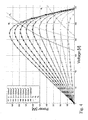
- Figure 3 shows a first embodiment of the single stage inverter device according to the invention, that meets the constraints represented by equations [13], [14], [21], [23] and [30], and that further minimises the three merit figures ⁇ 1 , ⁇ 2 , and ⁇ 3 represented by equations [31]-[33].
- the device of Figure 3 comprises four semiconductor power switches M1-M4 (preferably implemented through respective MOSFETs or IGBTs), the gate terminals of which are controlled by the controller 10.
- the controller 10 receives as inputs the voltage v g (t) of the photovoltaic field 1, the ac voltage v o (t) of the grid 2, and the value of the voltage drop on the resistor R s sensing the inverter output current i o (t).
- the gate terminals of the four switches M1, M2, M3 and M4 are controlled so that, during the time interval in which the voltage of grid 2 presents positive values with respect to the polarity indicated in Figure 3 , M4 is closed (i.e., conducting), M2 and M3 are open (i.e., not conducting) while M1 is being closed and open with period Ts, so that M1 is conducting during the first part of the switching period Ts, of length equal to the product of the switching duty-cycle multiplied by the switching period Ts, and vice versa M1 is off for a time equal to the remaining part of the switching period Ts; vice versa, the gate terminals of the four switches M1, M2, M3 and M4 are controlled so that, during the time interval in which the voltage of grid 2 presents negative values with respect to the polarity indicated in Figure 3 , M2 is closed (i.e.
- M4 and M1 are open (i.e., not conducting) while M3 is closed and open with period Ts, so that M3 is conducting during the first part of the switching period Ts, of length equal to the product of the switching duty-cycle multiplied by the switching period Ts, and vice versa M3 is off for a time equal to the remaining part of the switching period Ts.
- the input R of the flip-flop 12 receives the output signal of a comparator 14, the non inverting input of which receives the absolute value of the voltage drop on the sensing resistor Rs (i.e.
- the flip-flop 12 adjusts the duty cycle of the signals for controlling the gates of the switches M 1-M4.
- the search space SP of the set of the values of the parameters is defined in Table I.
- the search range for the sensing resistance R s is defined so as to prevent saturation phenomena of the operational amplifiers.
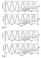
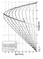
- Figure 4 shows the power curves of the photovoltaic field 1 corresponding to ten levels of sunlight S, and the three operation curves P o (V g ) of the photovoltaic OCC inverter corresponding to the three sets of values of the design parameters ensuring the minimum values of the three merit figures ⁇ 1 , ⁇ 2 , and ⁇ 3 , obtained after an estimation with the Montecarlo method with 2 ⁇ 10 5 trials for each one of the three merit figures described above.
- Table II summarises the values of the parameters corresponding to the three design solutions which minimise the three merit figures ⁇ 1 , ⁇ 2 , and ⁇ 3 and the corresponding power levels obtained at maximum and minimum sunlight.
- the inverter characteristic curve P 0 (V g ) obtained by minimising the first merit figure ⁇ 1 corresponds to an design solution that is unsatisfactory at high levels of sunlight S, while the other two solutions present better, although not optimal, performance.
- the waveforms of the inverter output currents compared with the reference waveform of the grid voltage, shown in Figure 5 , obtained through circuit simulation performed by using the software PSIM ® , shows the high PF-out attained at both high and low levels of sunlight S (respectively, Fig. 5a and Fig. 5b ) with the set of parameter values minimising the second merit figure ⁇ 2 .
- the solutions summarised in Table II may be improved if a larger number of trials in the Montecarlo method is used. For instance, with 8.10 5 trials, the solutions summarised in Table III are obtained, while Figure 6 shows the corresponding three operation curves P o (V g ) of the photovoltaic OCC inverter (superimposed on the power curves of the photovoltaic field 1 corresponding to ten levels of sunlight S), and Figure 7 shows the simulated waveforms of the inverter output currents, compared with the reference waveform of the grid voltage, corresponding to the set of parameter values minimising the second merit figure ⁇ 2 ( Fig. 7a for high sunlight levels and Fig. 7b for low levels of sunlight S).
- Table IV summarises the values of the optimal sets of parameters minimising the second merit figure ⁇ 2 obtained by means of the two previous Montecarlo methods and the values of the set obtained through the known genetic algorithm Genocop, while Figure 8 shows the corresponding operation curves P o (V g ) of the photovoltaic OCC inverter.
- Figures 10 and 11 instead show the simulated dynamic behaviour of the inverter corresponding to such set of the parameter values obtained through genetic optimisation in the maximum power point tracking in presence of sunlight S variable during a time interval equal to about 20 seconds.
- Figure 10a shows the inverter output current, compared with reference waveform of the grid voltage, in correspondence with the sub-interval of time ranging from 11.5 seconds to 11.6 seconds
- Figure 11 shows the corresponding shift, during the same time interval, of the operation point over the inverter output power-voltage characteristic curves.
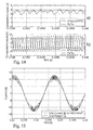
- Figure 14 shows the waveforms of the two inputs of the comparator 14 of Figure 3 in cases of violation ( Figure 14a ) and of fulfilment ( Figure 14b ) of the constraint [14]: in the first case, the phase inversion of the voltage at the non inverting input terminal of the comparator 14 does not allow the periodic operation at fixed switching frequency f s , instead occurring in the second case, and it determines a strong distortion of the output current i o (t), as shown in Figure 15 .
- the device developed by the inventors is not scaled so as to meet the following constraint: V m > K ⁇ V o , max D max where D max is the maximum value of the duty-cycle admissible for the circuit.
- Table VII shows the set of parameters obtained after an estimation with the Montecarlo method with 8 ⁇ 10 5 trials for each one of the three merit figures described above and including the constraint [34].
- the photovoltaic single stage inverter device shown in Figure 3 allows to attain a significant improvement in terms of performance both for the power part and for the control part, at low cost, since the controller 10 is implementable through analog circuitry with parameters optimised through the described process imposing the constraints represented by equations [13], [14], [21], [23] and [30], and minimising the three merit figures ⁇ 1 , ⁇ 2 , and ⁇ 3 represented by equations [31]-[33].
- the operation point of the inverter device of Figure 3 in terms of output power as a function of the voltage vg(t) of the photovoltaic field 1 remains moving along a fixed path, identified by the set of parameters ⁇ K, K g , R s , V c , ⁇ , intersecting the maximum power point of the photovoltaic field only in particular environmental conditions, remaining in the proximity of it in the other cases, at a distance depending on the level of instant sunlight S and on the instant temperature T.
- a second embodiment of the device according to the invention integrates in a different controller 20 the analog controller 10 of Figure 3 with a digital unit 21, achieving a function of the perturb and observe or P&O type and operating on the OCC controller parameters in order to attain the real maximum power point tracking MPPT.
- the P&O MPPT technique perturbs the operation voltage vg(t) of the photovoltaic field 1 according to the so called hill climbing method.
- the voltage vg(t) is perturbed in a given direction (i.e., by either increasing or decreasing it), through a variation of the duty-cycle value of the inverter of the converter connected with its input to the photovoltaic field 1 and with its output to the grid 2.
- the instant output voltage and current of the photovoltaic field 1 are detected by the digital unit 21 that evaluates their product (i.e., the field output electric power): if this is higher than that detected after the last preceding perturbation, then the voltage vg(t) is furthermore varied in the same direction, otherwise the direction of perturbation of the voltage vg(t) is reversed.
- the digital unit 21 evaluates their product (i.e., the field output electric power): if this is higher than that detected after the last preceding perturbation, then the voltage vg(t) is furthermore varied in the same direction, otherwise the direction of perturbation of the voltage vg(t) is reversed.
- the P&O MPPT technique is applied to the perturbation of the sole parameter V c , that along with the other ones determine the behaviour of the inverter output power P0 curve, thus making such curve dynamic and in this way achieving the possibility of obtaining an intersection between the aforesaid curve and the characteristic curve of the photovoltaic field power P g in correspondence with the maximum power point MPP, in any conditions of sunlight S and panel temperature T.
- embodiments of the device according to the invention may apply the P&O MPPT technique to the perturbation of one or more of the five parameters (K, K g , R s , V c , ⁇ ) of the inverter or of any combination of two or more of them.
- the efficiency of the P&O MPPT technique may be maximised by suitably setting the period T a of sampling the voltage vg(t) and the current ig(t) of the photovoltaic field 1 (with T a >T s ) and the amplitude ⁇ d of the duty-cycle perturbation.
- the sampling period T a must be chosen as a function of the dynamics of the whole system given by the assembly constituted by the photovoltaic field 1 and the converter comprising the inverter, in order to avoid mistakes in MPPT tracking.
- the correct setting of duty-cycle perturbation amplitude ⁇ d also prevents the operating point of the photovoltaic field 1 from oscillating around the MPP maximum power point, and allows to optimise the response speed of the controller 20 under fast variations of sunlight S.
- the device of Figure 18 has as set of starting parameter values the one summarised in Table IV obtained through the known genetic algorithm Genocop, the digital unit 21 operating according to the illustrated P&O MPPT technique determining subsequent variations of the control voltage V c within the range 3.4091 V to 5.0489 V, fulfilling constraint equations [13], [14], [21], [23], and [30].
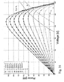
- the locus of operation points corresponding to the inverter output power P0 obtainable by making the voltage V c vary within the range indicated above is shown in Figure 19 , and it is in fact represented by the surface delimitated by the two extreme curves corresponding to the two minimum and maximum values V c_min and V c_max of the voltage V c .
- Such surface includes all the possible MPP maximum power points of the photovoltaic field 1 within the range of considered values of sunlight S (belonging to the range 100 W/m 2 to 1000 W/m 2 ).
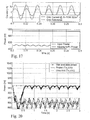
- Figure 21 shows the corresponding behaviours of the respective control voltages V c . The better performance of the optimal case is self-evident.
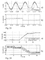
- Figure 23 shows the waveform of the output current io(t) (compared with the reference waveform of the grid voltage 2, Fig. 23a ) and the time behaviour of the control voltage V c ( Fig. 23b ) in a time sub-interval of Figure 22 ranging from 12.67 s to 12.73 s (wherein the control voltage V c is subjected to a variation), from which it is evident that the quality of the waveform of the output current io(t) is maintained thanks to the presence of the P&O MPPT control.
- Figure 24 shows the time behaviours of the output power P 0 (compared with the maximum power available from the photovoltaic field 1, Figure 24a ), and of the control voltage V c ( Fig. 24b ) in presence of combined variations of sunlight S and panel temperature T.
- the very high inverter performance in terms of maximum power point tracking MPPT are evident.
Landscapes
- Engineering & Computer Science (AREA)
- Radar, Positioning & Navigation (AREA)
- Life Sciences & Earth Sciences (AREA)
- Sustainable Energy (AREA)
- Power Engineering (AREA)
- Physics & Mathematics (AREA)
- Electromagnetism (AREA)
- Sustainable Development (AREA)
- Automation & Control Theory (AREA)
- General Physics & Mathematics (AREA)
- Control Of Electrical Variables (AREA)
- Inverter Devices (AREA)
- Supply And Distribution Of Alternating Current (AREA)
- Circuit Arrangements For Discharge Lamps (AREA)
- Power Conversion In General (AREA)
- Emergency Protection Circuit Devices (AREA)
Claims (25)
- Dispositif inverseur à étage unique pour convertisseurs de puissance à partir de sources d'énergie à courant continu (1) vers un réseau électrique ou grille (2) à courant alternatif d'au moins une phase, de fréquence de pulsation ωgrid, dispositif comprenant des moyens de commutation (M1-M4) capables de connecter périodiquement, avec une période Ts intérieure à la période Tgrid correspondant à la fréquence de pulsation ωgrid, une source (1), capable de délivrer en sortie une tension vg(t) de valeur moyenne Vg, à la grille (2) de telle sorte que le courant de sortie i0(t) du dispositif soit en phase avec la tension v0(t) d'au moins une phase de la grille (2), dont la valeur maximum est Vo,max, les moyens de commutation (M1-M4) étant commandés par des moyens électroniques de commande (10, 20) fonctionnant selon une commande sur un cycle de commutation unique des moyens de commutation (M1-M4), le dispositif étant pourvu d'une inductance de sortie L, le dispositif comprenant une résistance de détection de résistance Rs connectée en série à la grille (2), le moyen électronique de commande (10, 20) comprenant :- un circuit intégrateur (9) pouvant être remis à zéro, ayant une constante de temps T telle que T < Ts, dont l'entrée reçoit un signal de tension (Vc-Kg*vg) égal à la différence entre une tension de commande Vc et une tension proportionnelle, d'un premier facteur Kg, à la tension de sortie Vg(t) de la source (1),- un moyen comparateur (14), apte à délivrer en sortie un signal indiquant la comparaison d'une chute de tension [Rs.io(t)] sur la résistance de détection avec la somme du signal de sortie du circuit intégrateur (9) et d'une tension [K.vo(t)] proportionnelle, d'un second facteur K, à la tension v0(t) de la grille (2), et- un moyen générateur (11, 12, 13) capable de recevoir le signal de sortie émis par le moyen comparateur (14) et un signal indiquant la phase de la grille (2) pour fournir un ou plusieurs signaux pour la commande des moyens de commutation (M1-M4),
la tension de commande Vc et le premier facteur Kg étant de nature à satisfaire la première contrainte suivante :
le dispositif étant caractérisé en ce qu'il satisfait une seconde contrainte, par laquelle le signal d'entrée du circuit intégrateur (9) est toujours positif, en ce qu'il satisfait une troisième contrainte par laquelle, à tout instant, la tension d'entrée des moyens de commutation (M1-M4) est supérieure à leur tension de sortie, et en ce qu'il satisfait une quatrième contrainte par laquelle
où :- - Po(S) est la puissance moyenne de sortie du dispositif pour un ensemble S de conditions de fonctionnement,- Pg·MPP(Smax) est la puissance maximale pouvant être délivrée par la source (1),- α est un premier coefficient de surcharge : α ≥ 1, et- y est un second coefficient : γ < 1.
 - Dispositif selon la revendication 1, caractérisé en ce que la tension de commande Vc et le premier facteur Kg sont tels que :

où ΔVg est l'amplitude crête à crête de l'oscillation de la tension Vg(t). - Dispositif selon la revendication 1 ou 2, caractérisé en ce que le second facteur K est tel que :

où ΔVg est l'amplitude crête à crête de l'oscillation de la tension vg(t). - Dispositif selon l'une quelconque des revendications précédentes, caractérisé en ce que le circuit intégrateur (9) pouvant être remis à zéro est remis à zéro lorsque

- Dispositif selon l'une quelconque des revendications précédentes, caractérisé en ce que le moyen électronique de commande (10, 20) comprend, en outre, un moyen électronique de traitement (21), relié à son entrée à la source (1) pour en déterminer la puissance avec une période d'échantillonnage Ta, capable de délivrer en sortie au moins un signal apte à faire varier la valeur d'au moins un paramètre correspondant, choisi dans le groupe comprenant la résistance Rs, la constante de temps T, la tension de commande Vc, le premier facteur Kg, le second facteur K, et une combinaison de ceux-ci, en perturbant en continu la puissance moyenne de sortie Po(S) afin de rechercher le point de puissance de sortie maximale selon la méthode de recherche des extrêmes, dite du 'hill climbing'.
- Dispositif selon la revendication 5, caractérisé en ce que le moyen électronique de traitement (21) est capable de détecter la tension et le courant de sortie instantanés de la source (1).
- Dispositif selon la revendication 5 ou 6, caractérisé en ce que Ta > Ts.
- Dispositif selon l'une quelconque des revendications 5 à 7, caractérisé en ce que le moyen électronique de traitement (21) délivre en sortie la tension de commande Vc, qui est fournie comme entrée au circuit intégrateur (9).
- Dispositif selon l'une quelconque des revendications précédentes, caractérisé en ce que les moyens électroniques de commande (10, 20) sont au moins partiellement intégrés dans au moins un microprocesseur et/ou au moins un processeur de signaux numériques et/ou au moins un microcontrôleur.
- Dispositif selon l'une quelconque des revendications précédentes, caractérisé en ce que la source (1) est telle que le point de puissance d'entrée maximale du dispositif est variable et/ou le facteur de puissance de sortie ou PF-out du dispositif est variable en fonction de l'ensemble S des conditions de fonctionnement.
- Dispositif selon la revendication 10, caractérisé en ce que la source (1) est une source d'énergie renouvelable.
- Dispositif selon la revendication 11, caractérisé en ce que la source (1) est une source photovoltaïque, les conditions de fonctionnement de l'ensemble S étant une ou plusieurs conditions choisies dans le groupe comprenant le niveau de lumière du soleil, la température et la dégradation de la source.
- Dispositif selon l'une quelconque des revendications précédentes, caractérisé en ce que le réseau électrique (2) est un réseau monophasé ou triphasé.
- Procédé à cycle de commutation unique de commande de moyens de commutation (M1-M4) d'un dispositif inverseur à étage unique, pour des convertisseurs de puissance à partir de sources d'énergie à courant continu (1) vers un réseau électrique ou grille (2) à courant alternatif d'au moins une phase, de fréquence de pulsation ωgrid, procédé dans lequel les moyens de commutation (M1-M4) connectent périodiquement, avec une période Ts inférieure à la période Tgrid correspondant à la fréquence de pulsation ωgrid, une source (1), capable de délivrer en sortie une tension vg(t) de valeur moyenne Vg, à la grille (2) de telle sorte que le courant de sortie i0(t) du dispositif de chaque phase soit en phase avec la tension v0(t) de la même phase de la grille (2) dont la valeur maximum est Vo,max, le procédé comprenant les étapes suivantes :A. intégrer, selon une constante de temps T telle que T<Ts, un signal de tension (Vc-Kg*vg) égal à la différence entre une tension de commande Vc et une tension proportionnelle d'un premier facteur Kg à la tension de sortie Vg(t) de la source (1),B. comparer une chute de tension [Rs.io(t)], sur une résistance de détection de résistance Rs connectée en série à la grille (2), avec la somme du résultat de l'intégration de l'étape A avec une tension [K.vo(t)] proportionnelle d'un second facteur K à la tension v0(t) de la grille (2), etC. générer un ou plusieurs signaux de commande des moyens de commutation (M1-M4) sur la base du résultat de la comparaison de l'étape B,
la tension de commande Vc et le premier facteur Kg étant de nature à satisfaire la première contrainte suivante :
où L est l'inductance de sortie vue par le dispositif inverseur, le procédé étant caractérisé en ce que le signal de tension intégré dans l'étape A est toujours positif, en ce que la tension d'entrée des moyens de commutation (M1-M4) est supérieure à leur tension de sortie, et en ce que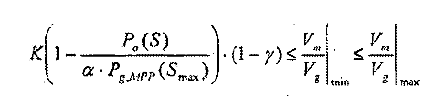

où :-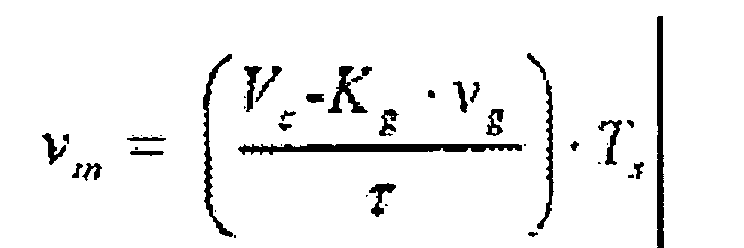 - Po(S) est la puissance moyenne de sortie du dispositif pour un ensemble S de conditions de fonctionnement,- Pg·MPP(Smax) est la puissance maximale pouvant être délivrée par la source (1),- α est un premier coefficient de surcharge : α ≥ 1, et- γ est un second coefficient : γ < 1.
 - Procédé selon la revendication 14, caractérisé en ce que la tension de commande Vc et le premier facteur Kg sont tels que :

où ΔVg est l'amplitude crête à crête de l'oscillation de la tension vg(t). - Procédé selon la revendication 14 ou 15, caractérisé en ce que le second facteur K est tel que :

où ΔVg est l'amplitude crête à crête de l'oscillation de la tension vg(t). - Procédé selon l'une quelconque des revendications 14 à 15, caractérisé en ce que le résultat de l'intégration de l'étape A est remis à zéro lorsque

- Procédé de mise à l'échelle d'un dispositif inverseur selon l'une quelconque des revendications 1 à 13, caractérisé en ce que les valeurs de la résistance Rs, de la constante de temps T, de la tension de commande Vc, du premier facteur Kg, et du second facteur K sont de nature à minimiser au moins une figure de mérite choisie dans le groupe comprenant :- une figure de mérite ψ0 égale à :

où S0 est un ensemble S de conditions de fonctionnement spécifiques et Pg(S0) est la puissance délivrée par la source en correspondance avec l'ensemble S0 de conditions de fonctionnement spécifiques, et- une autre figure de mérite ψ3 égale à l'écart quadratique moyen de la puissance maximale Pg·MPP(Smax pouvant être délivrée par la source (1) et de la puissance de sortie Po(S) du dispositif sur une plage entière [Smin, Smax] d'ensembles S de conditions de fonctionnement, à savoir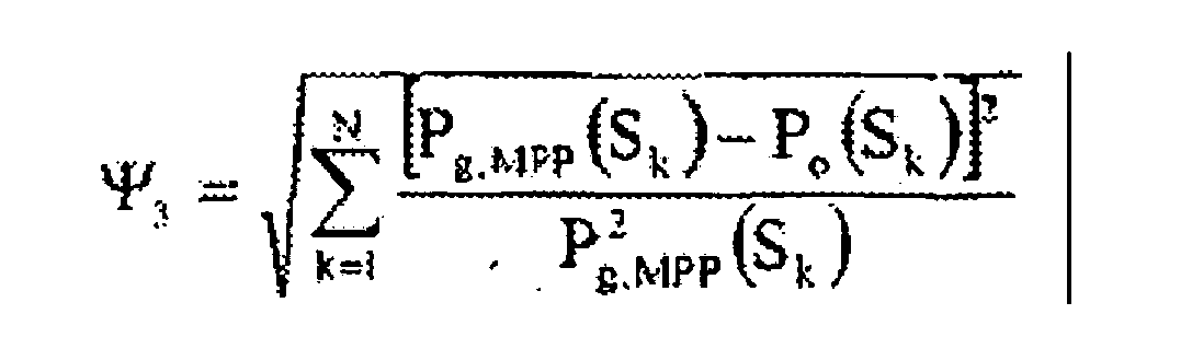
où Smin, Smax sont des ensembles de conditions de fonctionnement spécifiques, Pg·MPP(S) prenant respectivement la valeur minimum et la valeur maximum dans la plage [Smin, Smax]. - Procédé selon la revendication 18, caractérisé en ce que la figure de mérite ψ0= ψ1 est calculée pour l'ensemble Smin de conditions de fonctionnement spécifiques.
- Procédé selon la revendication 18 ou 19, caractérisé en ce que la figure de mérite ψ0= ψ2 est calculée pour l'ensemble Smax de conditions de fonctionnement spécifiques.
- Procédé selon l'une quelconque des revendications 16 à 20, caractérisé en ce que les valeurs de la résistance Rs, de la constante de temps T, de la tension de commande Vc, du premier facteur Kg et du second facteur K sont déterminées via au moins une technique numérique déterministe et stochastique.
- Procédé selon la revendication 21, caractérisé en ce que ladite au moins une technique numérique déterministe et stochastique comprend une estimation via la méthode de Montecarlo et/ou un type évolutif d'algorithmes de recherche, de préférence un algorithme génétique.
- Procédé selon l'une quelconque des revendications 18 à 22, caractérisé en ce que le dispositif est un dispositif selon la revendication 12.
- Dispositif contrôleur (10, 20) caractérisé en ce qu'il est capable de fonctionner en tant que moyen électronique de commande mezzo d'un dispositif inverseur à étage unique selon l'une quelconque des revendications 1 à 13.
- Dispositif contrôleur (10, 20) selon la revendication 24, caractérisé en ce qu'il est capable d'exécuter le procédé à cycle de commutation unique de commande des moyens de commutation selon l'une quelconque des revendications 14 à 17.
Applications Claiming Priority (2)
| Application Number | Priority Date | Filing Date | Title |
|---|---|---|---|
| IT000014A ITSA20050014A1 (it) | 2005-07-13 | 2005-07-13 | Dispositivo invertitore a singolo stadio, e relativo metodo di controllo, per convertitori di potenza da sorgenti di energia, in particolare sorgenti fotovoltaiche. |
| PCT/IT2005/000747 WO2007007360A2 (fr) | 2005-07-13 | 2005-12-20 | Inverseur a etage unique et procede de controle connexe pour convertisseurs de puissance a partir de sources d'energie, en particulier photovoltaiques |
Publications (2)
| Publication Number | Publication Date |
|---|---|
| EP1902349A2 EP1902349A2 (fr) | 2008-03-26 |
| EP1902349B1 true EP1902349B1 (fr) | 2010-08-18 |
Family
ID=37637598
Family Applications (1)
| Application Number | Title | Priority Date | Filing Date |
|---|---|---|---|
| EP05823480A Expired - Lifetime EP1902349B1 (fr) | 2005-07-13 | 2005-12-20 | Inverseur a etage unique et procede de controle connexe pour convertisseurs de puissance a partir de sources d'energie, en particulier photovoltaiques |
Country Status (10)
| Country | Link |
|---|---|
| US (1) | US8189352B2 (fr) |
| EP (1) | EP1902349B1 (fr) |
| CN (1) | CN101253461B (fr) |
| AT (1) | ATE478372T1 (fr) |
| CA (1) | CA2613038C (fr) |
| DE (1) | DE602005023069D1 (fr) |
| ES (1) | ES2350744T3 (fr) |
| IT (1) | ITSA20050014A1 (fr) |
| PT (1) | PT1902349E (fr) |
| WO (1) | WO2007007360A2 (fr) |
Cited By (1)
| Publication number | Priority date | Publication date | Assignee | Title |
|---|---|---|---|---|
| EP2399332A4 (fr) * | 2009-02-19 | 2017-08-02 | Xslent Energy Technologies, LLC | Gestion de transfert d'énergie pour sources d'énergie locales d'une charge liée à un réseau |
Families Citing this family (104)
| Publication number | Priority date | Publication date | Assignee | Title |
|---|---|---|---|---|
| US10693415B2 (en) | 2007-12-05 | 2020-06-23 | Solaredge Technologies Ltd. | Testing of a photovoltaic panel |
| US11881814B2 (en) | 2005-12-05 | 2024-01-23 | Solaredge Technologies Ltd. | Testing of a photovoltaic panel |
| US8013472B2 (en) | 2006-12-06 | 2011-09-06 | Solaredge, Ltd. | Method for distributed power harvesting using DC power sources |
| US11888387B2 (en) | 2006-12-06 | 2024-01-30 | Solaredge Technologies Ltd. | Safety mechanisms, wake up and shutdown methods in distributed power installations |
| US11855231B2 (en) | 2006-12-06 | 2023-12-26 | Solaredge Technologies Ltd. | Distributed power harvesting systems using DC power sources |
| US11735910B2 (en) | 2006-12-06 | 2023-08-22 | Solaredge Technologies Ltd. | Distributed power system using direct current power sources |
| US12316274B2 (en) | 2006-12-06 | 2025-05-27 | Solaredge Technologies Ltd. | Pairing of components in a direct current distributed power generation system |
| US8473250B2 (en) | 2006-12-06 | 2013-06-25 | Solaredge, Ltd. | Monitoring of distributed power harvesting systems using DC power sources |
| US9130401B2 (en) | 2006-12-06 | 2015-09-08 | Solaredge Technologies Ltd. | Distributed power harvesting systems using DC power sources |
| US8319471B2 (en) | 2006-12-06 | 2012-11-27 | Solaredge, Ltd. | Battery power delivery module |
| US11309832B2 (en) | 2006-12-06 | 2022-04-19 | Solaredge Technologies Ltd. | Distributed power harvesting systems using DC power sources |
| US8319483B2 (en) | 2007-08-06 | 2012-11-27 | Solaredge Technologies Ltd. | Digital average input current control in power converter |
| US8963369B2 (en) | 2007-12-04 | 2015-02-24 | Solaredge Technologies Ltd. | Distributed power harvesting systems using DC power sources |
| US8947194B2 (en) | 2009-05-26 | 2015-02-03 | Solaredge Technologies Ltd. | Theft detection and prevention in a power generation system |
| US8816535B2 (en) | 2007-10-10 | 2014-08-26 | Solaredge Technologies, Ltd. | System and method for protection during inverter shutdown in distributed power installations |
| US8384243B2 (en) | 2007-12-04 | 2013-02-26 | Solaredge Technologies Ltd. | Distributed power harvesting systems using DC power sources |
| US11296650B2 (en) | 2006-12-06 | 2022-04-05 | Solaredge Technologies Ltd. | System and method for protection during inverter shutdown in distributed power installations |
| US8618692B2 (en) | 2007-12-04 | 2013-12-31 | Solaredge Technologies Ltd. | Distributed power system using direct current power sources |
| US9112379B2 (en) | 2006-12-06 | 2015-08-18 | Solaredge Technologies Ltd. | Pairing of components in a direct current distributed power generation system |
| US11569659B2 (en) | 2006-12-06 | 2023-01-31 | Solaredge Technologies Ltd. | Distributed power harvesting systems using DC power sources |
| US9088178B2 (en) | 2006-12-06 | 2015-07-21 | Solaredge Technologies Ltd | Distributed power harvesting systems using DC power sources |
| US11687112B2 (en) | 2006-12-06 | 2023-06-27 | Solaredge Technologies Ltd. | Distributed power harvesting systems using DC power sources |
| WO2009055474A1 (fr) | 2007-10-23 | 2009-04-30 | And, Llc | Systèmes d'alimentation à haute fiabilité et convertisseurs d'énergie solaire |
| CN101904073B (zh) | 2007-10-15 | 2014-01-08 | Ampt有限公司 | 高效太阳能电力系统 |
| WO2009072075A2 (fr) | 2007-12-05 | 2009-06-11 | Solaredge Technologies Ltd. | Procédé de suivi de puissance d'un système photovoltaïque |
| US11264947B2 (en) | 2007-12-05 | 2022-03-01 | Solaredge Technologies Ltd. | Testing of a photovoltaic panel |
| EP3496258B1 (fr) | 2007-12-05 | 2025-02-05 | Solaredge Technologies Ltd. | Mécanismes de sécurité dans des installations de puissance réparties |
| US8049523B2 (en) | 2007-12-05 | 2011-11-01 | Solaredge Technologies Ltd. | Current sensing on a MOSFET |
| EP2232690B1 (fr) | 2007-12-05 | 2016-08-31 | Solaredge Technologies Ltd. | Onduleurs connectés en parallèle |
| EP4145691A1 (fr) | 2008-03-24 | 2023-03-08 | Solaredge Technologies Ltd. | Convertisseur à découpage avec circuit auxiliaire de commutation par courant nul |
| EP3121922B1 (fr) | 2008-05-05 | 2020-03-04 | Solaredge Technologies Ltd. | Combineur de puissance en courant continu |
| KR100993108B1 (ko) * | 2008-05-30 | 2010-11-08 | 군산대학교산학협력단 | 전력품질개선 및 절전기능을 갖는 계통연계형 태양광발전시스템 |
| KR100983035B1 (ko) * | 2008-06-23 | 2010-09-17 | 삼성전기주식회사 | 최대 전력 추종 기능을 갖는 전원 장치 |
| EP2345129B1 (fr) * | 2008-09-26 | 2020-02-19 | Xslent Energy Technologies, LLC | Génération et commande adaptative de formes d'ondes électriques arbitraires dans un système de conversion d'énergie raccordé au réseau |
| US7768155B2 (en) | 2008-10-10 | 2010-08-03 | Enphase Energy, Inc. | Method and apparatus for improved burst mode during power conversion |
| EP2376993B1 (fr) | 2009-01-07 | 2017-09-06 | ABB Schweiz AG | Procédé et système d'extraction d'énergie électrique a partir d'une source d'énergie renouvelable |
| US20100171482A1 (en) * | 2009-01-08 | 2010-07-08 | Yang Ye | Method and apparatus of a maximum power point tracking circuit for solar power generation |
| ITSA20090004A1 (it) * | 2009-02-20 | 2010-08-21 | Univ Degli Studi Salerno | Metodo di controllo di un sistema di generazione di potenza elettrica basato su sorgenti di energia, in particolare sorgenti di energia rinnovabile, e relativo dispositivo controllore. |
| US9442504B2 (en) | 2009-04-17 | 2016-09-13 | Ampt, Llc | Methods and apparatus for adaptive operation of solar power systems |
| US8614903B2 (en) * | 2009-08-24 | 2013-12-24 | Mitsubishi Electric Corporation | Power conditioner for photovoltaic power generation |
| CN102598455B (zh) * | 2009-09-18 | 2017-06-20 | 金斯顿女王大学 | 分布式发电接口 |
| US9466737B2 (en) | 2009-10-19 | 2016-10-11 | Ampt, Llc | Solar panel string converter topology |
| US12418177B2 (en) | 2009-10-24 | 2025-09-16 | Solaredge Technologies Ltd. | Distributed power system using direct current power sources |
| CA2781288A1 (fr) * | 2009-12-16 | 2011-06-23 | Eds-Usa Inc. | Chauffage photovoltaique |
| DE102010026299A1 (de) * | 2010-07-06 | 2012-01-12 | Phoenix Contact Gmbh & Co. Kg | Verfahren zur Steuerung von PV-Anlagen in einem Stromversorgungsnetz |
| US9035626B2 (en) | 2010-08-18 | 2015-05-19 | Volterra Semiconductor Corporation | Switching circuits for extracting power from an electric power source and associated methods |
| US9331499B2 (en) | 2010-08-18 | 2016-05-03 | Volterra Semiconductor LLC | System, method, module, and energy exchanger for optimizing output of series-connected photovoltaic and electrochemical devices |
| GB2485527B (en) | 2010-11-09 | 2012-12-19 | Solaredge Technologies Ltd | Arc detection and prevention in a power generation system |
| US10673222B2 (en) | 2010-11-09 | 2020-06-02 | Solaredge Technologies Ltd. | Arc detection and prevention in a power generation system |
| US10230310B2 (en) | 2016-04-05 | 2019-03-12 | Solaredge Technologies Ltd | Safety switch for photovoltaic systems |
| US10673229B2 (en) | 2010-11-09 | 2020-06-02 | Solaredge Technologies Ltd. | Arc detection and prevention in a power generation system |
| US8513913B2 (en) | 2010-12-03 | 2013-08-20 | Morningstar Corporation | Photovoltaic system charge controller having buck converter with reversed MOSFETS |
| GB2486408A (en) | 2010-12-09 | 2012-06-20 | Solaredge Technologies Ltd | Disconnection of a string carrying direct current |
| TWI413332B (zh) * | 2010-12-29 | 2013-10-21 | 中興電工機械股份有限公司 | 電力轉換電路 |
| GB2483317B (en) | 2011-01-12 | 2012-08-22 | Solaredge Technologies Ltd | Serially connected inverters |
| EP2503427A1 (fr) * | 2011-03-23 | 2012-09-26 | ABB Research Ltd. | Procédé pour la recherche d'un point global d'alimentation maximum |
| US20130009700A1 (en) * | 2011-07-08 | 2013-01-10 | Infineon Technologies Ag | Power Converter Circuit with AC Output |
| GB201113519D0 (en) * | 2011-08-04 | 2011-09-21 | Control Tech Ltd | Maximum power point tracker |
| US20130043857A1 (en) * | 2011-08-19 | 2013-02-21 | Texas Instruments Incorporated | Hysteretic charger for energy harvester devices |
| TWI444807B (zh) * | 2011-08-23 | 2014-07-11 | 國立成功大學 | 換流器之類比控制器 |
| US8570005B2 (en) | 2011-09-12 | 2013-10-29 | Solaredge Technologies Ltd. | Direct current link circuit |
| DE102011054939A1 (de) * | 2011-10-28 | 2013-05-02 | Sma Solar Technology Ag | Nachführverfahren und -einrichtung für einen Spannungswandler für eine Photovoltaikanlage |
| US9837556B2 (en) | 2011-10-31 | 2017-12-05 | Volterra Semiconductor LLC | Integrated photovoltaic panel with sectional maximum power point tracking |
| JP2013097596A (ja) * | 2011-11-01 | 2013-05-20 | Sony Corp | 太陽電池システム、電子機器および建築物 |
| EP2774014A4 (fr) | 2011-11-04 | 2015-08-26 | Zbb Energy Corp | Système et procédé pour la conversion d'énergie pour des sources d'énergie renouvelable |
| TWI438602B (zh) | 2011-12-02 | 2014-05-21 | Ind Tech Res Inst | 最大功率點追蹤控制器、最大功率點追蹤系統和最大功率點追蹤方法 |
| CN102570875A (zh) * | 2011-12-16 | 2012-07-11 | 西安理工大学 | 能量回馈式高频隔离型电力电子变换电路及光伏发电系统 |
| GB2498365A (en) | 2012-01-11 | 2013-07-17 | Solaredge Technologies Ltd | Photovoltaic module |
| GB2498790A (en) | 2012-01-30 | 2013-07-31 | Solaredge Technologies Ltd | Maximising power in a photovoltaic distributed power system |
| GB2498791A (en) | 2012-01-30 | 2013-07-31 | Solaredge Technologies Ltd | Photovoltaic panel circuitry |
| US9853565B2 (en) | 2012-01-30 | 2017-12-26 | Solaredge Technologies Ltd. | Maximized power in a photovoltaic distributed power system |
| GB2499991A (en) | 2012-03-05 | 2013-09-11 | Solaredge Technologies Ltd | DC link circuit for photovoltaic array |
| US10115841B2 (en) | 2012-06-04 | 2018-10-30 | Solaredge Technologies Ltd. | Integrated photovoltaic panel circuitry |
| RU2513024C2 (ru) * | 2012-07-09 | 2014-04-20 | Федеральное государственное бюджетное образовательное учреждение высшего профессионального образования "Южно-Уральский государственный университет" (национальный исследовательский университет) (ФГБОУ ВПО "ЮУрГУ" (НИУ)) | Адаптивное интегрирующее устройство синхронизации |
| TWI475795B (zh) * | 2012-08-22 | 2015-03-01 | 國立成功大學 | 光伏變流器及其控制方法 |
| CN102880223A (zh) * | 2012-09-27 | 2013-01-16 | 易霸科技(威海)股份有限公司 | 一种小功率光伏逆变系统mppt的模拟电路实现方法 |
| US9141123B2 (en) | 2012-10-16 | 2015-09-22 | Volterra Semiconductor LLC | Maximum power point tracking controllers and associated systems and methods |
| US10270251B1 (en) * | 2012-10-24 | 2019-04-23 | National Technology & Engineering Solutions Of Sandia, Llc | Emulator apparatus for microgrid testing and design |
| US8848726B1 (en) | 2013-01-24 | 2014-09-30 | The Intellisis Corporation | I/O data interface for packet processors |
| US9391540B2 (en) | 2013-02-12 | 2016-07-12 | Enphase Energy, Inc. | Method and apparatus for chaotic democratic pulse width modulation generation |
| US9548619B2 (en) | 2013-03-14 | 2017-01-17 | Solaredge Technologies Ltd. | Method and apparatus for storing and depleting energy |
| US9941813B2 (en) | 2013-03-14 | 2018-04-10 | Solaredge Technologies Ltd. | High frequency multi-level inverter |
| US9397497B2 (en) | 2013-03-15 | 2016-07-19 | Ampt, Llc | High efficiency interleaved solar power supply system |
| EP2779251B1 (fr) | 2013-03-15 | 2019-02-27 | Solaredge Technologies Ltd. | Mécanisme de dérivation |
| US10193347B2 (en) | 2013-03-29 | 2019-01-29 | Enphase Energy, Inc. | Method and apparatus for improved burst mode during power conversion |
| TWI470396B (zh) | 2013-06-26 | 2015-01-21 | 財團法人工業技術研究院 | 功率點追蹤方法與裝置 |
| US9318974B2 (en) | 2014-03-26 | 2016-04-19 | Solaredge Technologies Ltd. | Multi-level inverter with flying capacitor topology |
| JP6475942B2 (ja) * | 2014-09-25 | 2019-02-27 | ルネサスエレクトロニクス株式会社 | 半導体装置及びそれを備えた交流抵抗計測システム |
| US9876442B2 (en) * | 2014-10-10 | 2018-01-23 | The Regents Of The University Of California | Robust single-phase DC/AC inverter for highly varying DC voltages |
| TWI545418B (zh) * | 2014-11-28 | 2016-08-11 | 財團法人工業技術研究院 | 功率轉換器之控制電路及最大功率點的追蹤方法 |
| GB201513549D0 (en) * | 2015-07-31 | 2015-09-16 | Siemens Ag | Inverter |
| CN105450021B (zh) * | 2015-12-22 | 2018-08-24 | 西北工业大学 | 一种航空专用低压直流恒功率负载稳定方法 |
| US12057807B2 (en) | 2016-04-05 | 2024-08-06 | Solaredge Technologies Ltd. | Chain of power devices |
| US11177663B2 (en) | 2016-04-05 | 2021-11-16 | Solaredge Technologies Ltd. | Chain of power devices |
| US11018623B2 (en) | 2016-04-05 | 2021-05-25 | Solaredge Technologies Ltd. | Safety switch for photovoltaic systems |
| TWI626522B (zh) | 2016-08-15 | 2018-06-11 | 財團法人工業技術研究院 | 功率點追蹤方法及其裝置 |
| US10931104B2 (en) * | 2017-05-30 | 2021-02-23 | Solaredge Technologies Ltd. | System and method for interconnected elements of a power system |
| EP3413454A1 (fr) * | 2017-06-07 | 2018-12-12 | ABB Schweiz AG | Procédé de fonctionnement un onduleur et agencement d'onduleur |
| CN107505975B (zh) * | 2017-08-30 | 2023-03-14 | 浙江大学 | 一种用于太阳能发电的mppt模拟控制芯片 |
| WO2020219994A1 (fr) * | 2019-04-25 | 2020-10-29 | Aerovironment | Architecture de bus d'alimentation d'aéronef et stabilisation de bus d'alimentation |
| CN113036751A (zh) * | 2021-01-15 | 2021-06-25 | 上海电机学院 | 一种考虑虚拟储能的可再生能源微电网优化调度方法 |
| CN113793544B (zh) * | 2021-09-03 | 2023-09-22 | 河南省高压电器研究所有限公司 | 一种光伏系统控制算法的实验系统 |
| CN119519396A (zh) * | 2024-11-21 | 2025-02-25 | 扬州新概念电气有限公司 | 一种基于mppt技术的电容取电装置 |
| CN121097684B (zh) * | 2025-11-11 | 2026-02-24 | 大唐水电科学技术研究院有限公司 | 一种分布式光伏发电功率智能预测方法和系统 |
Family Cites Families (12)
| Publication number | Priority date | Publication date | Assignee | Title |
|---|---|---|---|---|
| US4375662A (en) * | 1979-11-26 | 1983-03-01 | Exxon Research And Engineering Co. | Method of and apparatus for enabling output power of solar panel to be maximized |
| US5077652A (en) * | 1990-10-18 | 1991-12-31 | Dynamote Corporation | Dual feedback loop DC-to-AC converter |
| JP3352334B2 (ja) * | 1996-08-30 | 2002-12-03 | キヤノン株式会社 | 太陽電池の電力制御装置 |
| US6111767A (en) * | 1998-06-22 | 2000-08-29 | Heliotronics, Inc. | Inverter integrated instrumentation having a current-voltage curve tracer |
| US6285572B1 (en) * | 1999-04-20 | 2001-09-04 | Sanyo Electric Co., Ltd. | Method of operating a power supply system having parallel-connected inverters, and power converting system |
| JP2002199614A (ja) * | 2000-12-28 | 2002-07-12 | Nec Corp | 太陽光電力充電装置 |
| CN1512286A (zh) * | 2002-12-30 | 2004-07-14 | 北京通力环电气股份有限公司 | 太阳能电源装置及其最大功率点跟踪控制方法 |
| US7256566B2 (en) * | 2003-05-02 | 2007-08-14 | Ballard Power Systems Corporation | Method and apparatus for determining a maximum power point of photovoltaic cells |
| EP1623495B1 (fr) | 2003-05-06 | 2009-10-07 | Enecsys Limited | Circuits d'alimentation electrique |
| TWI232361B (en) * | 2003-11-25 | 2005-05-11 | Delta Electronics Inc | Maximum-power tracking method and device of solar power generation system |
| WO2007072517A1 (fr) * | 2005-12-22 | 2007-06-28 | Power-One Italy S.P.A. | Systeme pour la production d'energie electrique a partir de sources renouvelables et son procede de commande |
| GB2454389B (en) * | 2006-01-13 | 2009-08-26 | Enecsys Ltd | Power conditioning unit |
-
2005
- 2005-07-13 IT IT000014A patent/ITSA20050014A1/it unknown
- 2005-12-20 CA CA2613038A patent/CA2613038C/fr not_active Expired - Fee Related
- 2005-12-20 AT AT05823480T patent/ATE478372T1/de active
- 2005-12-20 CN CN2005800510272A patent/CN101253461B/zh not_active Expired - Fee Related
- 2005-12-20 PT PT05823480T patent/PT1902349E/pt unknown
- 2005-12-20 ES ES05823480T patent/ES2350744T3/es not_active Expired - Lifetime
- 2005-12-20 DE DE602005023069T patent/DE602005023069D1/de not_active Expired - Lifetime
- 2005-12-20 WO PCT/IT2005/000747 patent/WO2007007360A2/fr not_active Ceased
- 2005-12-20 EP EP05823480A patent/EP1902349B1/fr not_active Expired - Lifetime
- 2005-12-20 US US11/993,453 patent/US8189352B2/en not_active Expired - Fee Related
Cited By (1)
| Publication number | Priority date | Publication date | Assignee | Title |
|---|---|---|---|---|
| EP2399332A4 (fr) * | 2009-02-19 | 2017-08-02 | Xslent Energy Technologies, LLC | Gestion de transfert d'énergie pour sources d'énergie locales d'une charge liée à un réseau |
Also Published As
| Publication number | Publication date |
|---|---|
| US8189352B2 (en) | 2012-05-29 |
| CA2613038A1 (fr) | 2007-01-18 |
| WO2007007360A2 (fr) | 2007-01-18 |
| ATE478372T1 (de) | 2010-09-15 |
| EP1902349A2 (fr) | 2008-03-26 |
| DE602005023069D1 (de) | 2010-09-30 |
| ITSA20050014A1 (it) | 2007-01-14 |
| CN101253461B (zh) | 2010-09-29 |
| CA2613038C (fr) | 2013-11-05 |
| HK1124670A1 (en) | 2009-07-17 |
| ES2350744T3 (es) | 2011-01-26 |
| US20100265747A1 (en) | 2010-10-21 |
| PT1902349E (pt) | 2010-11-23 |
| CN101253461A (zh) | 2008-08-27 |
| WO2007007360A3 (fr) | 2007-09-20 |
Similar Documents
| Publication | Publication Date | Title |
|---|---|---|
| EP1902349B1 (fr) | Inverseur a etage unique et procede de controle connexe pour convertisseurs de puissance a partir de sources d'energie, en particulier photovoltaiques | |
| Gupta et al. | A new gamma scaling maximum power point tracking method for solar photovoltaic panel Feeding energy storage system | |
| Jotham Jeremy et al. | Non-isolated conventional DC-DC converter comparison for a photovoltaic system: A review | |
| Yusof et al. | Modeling and simulation of maximum power point tracker for photovoltaic system | |
| Tse et al. | A comparative study of maximum-power-point trackers for photovoltaic panels using switching-frequency modulation scheme | |
| Cabal et al. | Maximum power point tracking based on sliding‐mode control for output‐series connected converters in photovoltaic systems | |
| Noman et al. | Simulation and Practical Implementation of ANFIS‐Based MPPT Method for PV Applications Using Isolated Ćuk Converter | |
| Gunasekaran et al. | An adaptive resistance perturbation based MPPT algorithm for photovoltaic applications | |
| Ananda-Rao et al. | Design of MPPT charge controller using zeta converter for battery integrated with solar Photovoltaic (PV) system | |
| Sangeetha et al. | Design and implementation of SEPIC converter based PV system using modified incremental conductance algorithm | |
| Kaliamoorthy et al. | Solar powered single stage boost inverter with ANN based MPPT algorithm | |
| Salem et al. | MPPT based on P&O control and FLC-Hill Climbing technique for a Photovoltaic Generator | |
| Abdillah et al. | Design of Maximum Power Point Tracking System Based on Single Ended Primary Inductor Converter Using Fuzzy Logic Controller. | |
| Maged et al. | Closed‐loop control of a single‐stage switched‐boost inverter in modified DC‐interconnected nanogrids | |
| Nag et al. | Solar PV based DC power supply for rural homes with analog, multiplier-less MPPT controller | |
| Gajadur et al. | A comparative analysis of Maximum Power Point Tracking (MPPT) Techniques of a Solar Panel | |
| Reddy et al. | An artificial intelligent MPPT controller based three level SEPIC topology for 1.2 kW solar PV system | |
| Kadri et al. | Design of a single-phase grid-connected photovoltaic system based on deadbeat current control with LCL filter | |
| Anandhakumar et al. | Integration of Modified Luo Converter and ANFIS MPPT in Grid-Tied Photovoltaic Systems | |
| Kadhem et al. | Improve the energy efficiency of PV systems by installing a soft switching boost converter with MPPT control | |
| Bizzarri et al. | Nonlinear analysis of a DC-DC boost converter working as a maximum power point tracker using analog-mixed-signal circuit simulation | |
| Shahida et al. | Implementation of sliding mode control for a buck converter in a photovoltaic system | |
| Sham et al. | i-Capacitor Voltage Control for PV Z-source System with Enhanced Shoot-through | |
| Jiao et al. | Fast simulation technique for photovoltaic power systems using simulink | |
| Arango Zuluaga et al. | Design of asymmetrical boost converters based on photovoltaic systems requirements |
Legal Events
| Date | Code | Title | Description |
|---|---|---|---|
| PUAI | Public reference made under article 153(3) epc to a published international application that has entered the european phase |
Free format text: ORIGINAL CODE: 0009012 |
|
| 17P | Request for examination filed |
Effective date: 20071214 |
|
| AK | Designated contracting states |
Kind code of ref document: A2 Designated state(s): AT BE BG CH CY CZ DE DK EE ES FI FR GB GR HU IE IS IT LI LT LU LV MC NL PL PT RO SE SI SK TR |
|
| AX | Request for extension of the european patent |
Extension state: AL BA HR MK YU |
|
| GRAP | Despatch of communication of intention to grant a patent |
Free format text: ORIGINAL CODE: EPIDOSNIGR1 |
|
| GRAS | Grant fee paid |
Free format text: ORIGINAL CODE: EPIDOSNIGR3 |
|
| GRAA | (expected) grant |
Free format text: ORIGINAL CODE: 0009210 |
|
| AK | Designated contracting states |
Kind code of ref document: B1 Designated state(s): AT BE BG CH CY CZ DE DK EE ES FI FR GB GR HU IE IS IT LI LT LU LV MC NL PL PT RO SE SI SK TR |
|
| AX | Request for extension of the european patent |
Extension state: YU |
|
| REG | Reference to a national code |
Ref country code: GB Ref legal event code: FG4D |
|
| REG | Reference to a national code |
Ref country code: CH Ref legal event code: EP |
|
| REG | Reference to a national code |
Ref country code: IE Ref legal event code: FG4D |
|
| REF | Corresponds to: |
Ref document number: 602005023069 Country of ref document: DE Date of ref document: 20100930 Kind code of ref document: P |
|
| REG | Reference to a national code |
Ref country code: PT Ref legal event code: SC4A Free format text: AVAILABILITY OF NATIONAL TRANSLATION Effective date: 20101116 |
|
| REG | Reference to a national code |
Ref country code: NL Ref legal event code: VDEP Effective date: 20100818 |
|
| REG | Reference to a national code |
Ref country code: GR Ref legal event code: EP Ref document number: 20100402707 Country of ref document: GR |
|
| LTIE | Lt: invalidation of european patent or patent extension |
Effective date: 20100818 |
|
| REG | Reference to a national code |
Ref country code: ES Ref legal event code: FG2A Effective date: 20110114 |
|
| PG25 | Lapsed in a contracting state [announced via postgrant information from national office to epo] |
Ref country code: LT Free format text: LAPSE BECAUSE OF FAILURE TO SUBMIT A TRANSLATION OF THE DESCRIPTION OR TO PAY THE FEE WITHIN THE PRESCRIBED TIME-LIMIT Effective date: 20100818 Ref country code: FI Free format text: LAPSE BECAUSE OF FAILURE TO SUBMIT A TRANSLATION OF THE DESCRIPTION OR TO PAY THE FEE WITHIN THE PRESCRIBED TIME-LIMIT Effective date: 20100818 |
|
| PG25 | Lapsed in a contracting state [announced via postgrant information from national office to epo] |
Ref country code: BG Free format text: LAPSE BECAUSE OF FAILURE TO SUBMIT A TRANSLATION OF THE DESCRIPTION OR TO PAY THE FEE WITHIN THE PRESCRIBED TIME-LIMIT Effective date: 20101118 Ref country code: CY Free format text: LAPSE BECAUSE OF FAILURE TO SUBMIT A TRANSLATION OF THE DESCRIPTION OR TO PAY THE FEE WITHIN THE PRESCRIBED TIME-LIMIT Effective date: 20100818 Ref country code: SI Free format text: LAPSE BECAUSE OF FAILURE TO SUBMIT A TRANSLATION OF THE DESCRIPTION OR TO PAY THE FEE WITHIN THE PRESCRIBED TIME-LIMIT Effective date: 20100818 Ref country code: PL Free format text: LAPSE BECAUSE OF FAILURE TO SUBMIT A TRANSLATION OF THE DESCRIPTION OR TO PAY THE FEE WITHIN THE PRESCRIBED TIME-LIMIT Effective date: 20100818 Ref country code: IS Free format text: LAPSE BECAUSE OF FAILURE TO SUBMIT A TRANSLATION OF THE DESCRIPTION OR TO PAY THE FEE WITHIN THE PRESCRIBED TIME-LIMIT Effective date: 20101218 |
|
| PG25 | Lapsed in a contracting state [announced via postgrant information from national office to epo] |
Ref country code: BE Free format text: LAPSE BECAUSE OF FAILURE TO SUBMIT A TRANSLATION OF THE DESCRIPTION OR TO PAY THE FEE WITHIN THE PRESCRIBED TIME-LIMIT Effective date: 20100818 Ref country code: LV Free format text: LAPSE BECAUSE OF FAILURE TO SUBMIT A TRANSLATION OF THE DESCRIPTION OR TO PAY THE FEE WITHIN THE PRESCRIBED TIME-LIMIT Effective date: 20100818 Ref country code: NL Free format text: LAPSE BECAUSE OF FAILURE TO SUBMIT A TRANSLATION OF THE DESCRIPTION OR TO PAY THE FEE WITHIN THE PRESCRIBED TIME-LIMIT Effective date: 20100818 Ref country code: SE Free format text: LAPSE BECAUSE OF FAILURE TO SUBMIT A TRANSLATION OF THE DESCRIPTION OR TO PAY THE FEE WITHIN THE PRESCRIBED TIME-LIMIT Effective date: 20100818 |
|
| PG25 | Lapsed in a contracting state [announced via postgrant information from national office to epo] |
Ref country code: DK Free format text: LAPSE BECAUSE OF FAILURE TO SUBMIT A TRANSLATION OF THE DESCRIPTION OR TO PAY THE FEE WITHIN THE PRESCRIBED TIME-LIMIT Effective date: 20100818 |
|
| PG25 | Lapsed in a contracting state [announced via postgrant information from national office to epo] |
Ref country code: CZ Free format text: LAPSE BECAUSE OF FAILURE TO SUBMIT A TRANSLATION OF THE DESCRIPTION OR TO PAY THE FEE WITHIN THE PRESCRIBED TIME-LIMIT Effective date: 20100818 Ref country code: RO Free format text: LAPSE BECAUSE OF FAILURE TO SUBMIT A TRANSLATION OF THE DESCRIPTION OR TO PAY THE FEE WITHIN THE PRESCRIBED TIME-LIMIT Effective date: 20100818 Ref country code: EE Free format text: LAPSE BECAUSE OF FAILURE TO SUBMIT A TRANSLATION OF THE DESCRIPTION OR TO PAY THE FEE WITHIN THE PRESCRIBED TIME-LIMIT Effective date: 20100818 Ref country code: SK Free format text: LAPSE BECAUSE OF FAILURE TO SUBMIT A TRANSLATION OF THE DESCRIPTION OR TO PAY THE FEE WITHIN THE PRESCRIBED TIME-LIMIT Effective date: 20100818 |
|
| PLBE | No opposition filed within time limit |
Free format text: ORIGINAL CODE: 0009261 |
|
| STAA | Information on the status of an ep patent application or granted ep patent |
Free format text: STATUS: NO OPPOSITION FILED WITHIN TIME LIMIT |
|
| 26N | No opposition filed |
Effective date: 20110519 |
|
| PG25 | Lapsed in a contracting state [announced via postgrant information from national office to epo] |
Ref country code: MC Free format text: LAPSE BECAUSE OF NON-PAYMENT OF DUE FEES Effective date: 20101231 |
|
| REG | Reference to a national code |
Ref country code: DE Ref legal event code: R097 Ref document number: 602005023069 Country of ref document: DE Effective date: 20110519 |
|
| PG25 | Lapsed in a contracting state [announced via postgrant information from national office to epo] |
Ref country code: HU Free format text: LAPSE BECAUSE OF FAILURE TO SUBMIT A TRANSLATION OF THE DESCRIPTION OR TO PAY THE FEE WITHIN THE PRESCRIBED TIME-LIMIT Effective date: 20110219 Ref country code: LU Free format text: LAPSE BECAUSE OF NON-PAYMENT OF DUE FEES Effective date: 20101220 |
|
| PGFP | Annual fee paid to national office [announced via postgrant information from national office to epo] |
Ref country code: IT Payment date: 20131223 Year of fee payment: 9 |
|
| PGFP | Annual fee paid to national office [announced via postgrant information from national office to epo] |
Ref country code: GB Payment date: 20141217 Year of fee payment: 10 Ref country code: IE Payment date: 20141209 Year of fee payment: 10 Ref country code: GR Payment date: 20141112 Year of fee payment: 10 Ref country code: TR Payment date: 20141125 Year of fee payment: 10 Ref country code: ES Payment date: 20141111 Year of fee payment: 10 Ref country code: CH Payment date: 20141212 Year of fee payment: 10 |
|
| PGFP | Annual fee paid to national office [announced via postgrant information from national office to epo] |
Ref country code: FR Payment date: 20141208 Year of fee payment: 10 Ref country code: AT Payment date: 20141125 Year of fee payment: 10 Ref country code: PT Payment date: 20141219 Year of fee payment: 10 |
|
| PG25 | Lapsed in a contracting state [announced via postgrant information from national office to epo] |
Ref country code: IT Free format text: LAPSE BECAUSE OF NON-PAYMENT OF DUE FEES Effective date: 20141220 |
|
| PGFP | Annual fee paid to national office [announced via postgrant information from national office to epo] |
Ref country code: DE Payment date: 20151217 Year of fee payment: 11 |
|
| REG | Reference to a national code |
Ref country code: PT Ref legal event code: MM4A Free format text: LAPSE DUE TO NON-PAYMENT OF FEES Effective date: 20160620 |
|
| REG | Reference to a national code |
Ref country code: CH Ref legal event code: PL |
|
| REG | Reference to a national code |
Ref country code: AT Ref legal event code: MM01 Ref document number: 478372 Country of ref document: AT Kind code of ref document: T Effective date: 20151220 |
|
| GBPC | Gb: european patent ceased through non-payment of renewal fee |
Effective date: 20151220 |
|
| PG25 | Lapsed in a contracting state [announced via postgrant information from national office to epo] |
Ref country code: PT Free format text: LAPSE BECAUSE OF NON-PAYMENT OF DUE FEES Effective date: 20160620 |
|
| REG | Reference to a national code |
Ref country code: IE Ref legal event code: MM4A |
|
| REG | Reference to a national code |
Ref country code: FR Ref legal event code: ST Effective date: 20160831 |
|
| REG | Reference to a national code |
Ref country code: GR Ref legal event code: ML Ref document number: 20100402707 Country of ref document: GR Effective date: 20160707 |
|
| PG25 | Lapsed in a contracting state [announced via postgrant information from national office to epo] |
Ref country code: LI Free format text: LAPSE BECAUSE OF NON-PAYMENT OF DUE FEES Effective date: 20151231 Ref country code: IE Free format text: LAPSE BECAUSE OF NON-PAYMENT OF DUE FEES Effective date: 20151220 Ref country code: GB Free format text: LAPSE BECAUSE OF NON-PAYMENT OF DUE FEES Effective date: 20151220 Ref country code: CH Free format text: LAPSE BECAUSE OF NON-PAYMENT OF DUE FEES Effective date: 20151231 |
|
| PG25 | Lapsed in a contracting state [announced via postgrant information from national office to epo] |
Ref country code: GR Free format text: LAPSE BECAUSE OF NON-PAYMENT OF DUE FEES Effective date: 20160707 Ref country code: FR Free format text: LAPSE BECAUSE OF NON-PAYMENT OF DUE FEES Effective date: 20151231 Ref country code: AT Free format text: LAPSE BECAUSE OF NON-PAYMENT OF DUE FEES Effective date: 20151220 |
|
| PG25 | Lapsed in a contracting state [announced via postgrant information from national office to epo] |
Ref country code: ES Free format text: LAPSE BECAUSE OF NON-PAYMENT OF DUE FEES Effective date: 20151221 |
|
| REG | Reference to a national code |
Ref country code: DE Ref legal event code: R119 Ref document number: 602005023069 Country of ref document: DE |
|
| PG25 | Lapsed in a contracting state [announced via postgrant information from national office to epo] |
Ref country code: TR Free format text: LAPSE BECAUSE OF NON-PAYMENT OF DUE FEES Effective date: 20151220 |
|
| PG25 | Lapsed in a contracting state [announced via postgrant information from national office to epo] |
Ref country code: DE Free format text: LAPSE BECAUSE OF NON-PAYMENT OF DUE FEES Effective date: 20170701 |
|
| REG | Reference to a national code |
Ref country code: ES Ref legal event code: FD2A Effective date: 20180704 |