EP1902641B1 - Zweiseitige Armbanduhr - Google Patents
Zweiseitige Armbanduhr Download PDFInfo
- Publication number
- EP1902641B1 EP1902641B1 EP06120862A EP06120862A EP1902641B1 EP 1902641 B1 EP1902641 B1 EP 1902641B1 EP 06120862 A EP06120862 A EP 06120862A EP 06120862 A EP06120862 A EP 06120862A EP 1902641 B1 EP1902641 B1 EP 1902641B1
- Authority
- EP
- European Patent Office
- Prior art keywords
- insert
- case
- wristwatch
- longitudinal
- indexing
- Prior art date
- Legal status (The legal status is an assumption and is not a legal conclusion. Google has not performed a legal analysis and makes no representation as to the accuracy of the status listed.)
- Active
Links
Images
Classifications
-
- A—HUMAN NECESSITIES
- A44—HABERDASHERY; JEWELLERY
- A44C—PERSONAL ADORNMENTS, e.g. JEWELLERY; COINS
- A44C5/00—Bracelets; Wrist-watch straps; Fastenings for bracelets or wrist-watch straps
- A44C5/14—Bracelets; Wrist-watch straps; Fastenings for bracelets or wrist-watch straps characterised by the way of fastening to a wrist-watch or the like
-
- G—PHYSICS
- G04—HOROLOGY
- G04B—MECHANICALLY-DRIVEN CLOCKS OR WATCHES; MECHANICAL PARTS OF CLOCKS OR WATCHES IN GENERAL; TIME PIECES USING THE POSITION OF THE SUN, MOON OR STARS
- G04B1/00—Driving mechanisms
- G04B1/02—Driving mechanisms with driving weight
-
- A—HUMAN NECESSITIES
- A44—HABERDASHERY; JEWELLERY
- A44C—PERSONAL ADORNMENTS, e.g. JEWELLERY; COINS
- A44C15/00—Other forms of jewellery
- A44C15/0025—Reversible or double face jewellery
-
- G—PHYSICS
- G04—HOROLOGY
- G04B—MECHANICALLY-DRIVEN CLOCKS OR WATCHES; MECHANICAL PARTS OF CLOCKS OR WATCHES IN GENERAL; TIME PIECES USING THE POSITION OF THE SUN, MOON OR STARS
- G04B1/00—Driving mechanisms
-
- G—PHYSICS
- G04—HOROLOGY
- G04B—MECHANICALLY-DRIVEN CLOCKS OR WATCHES; MECHANICAL PARTS OF CLOCKS OR WATCHES IN GENERAL; TIME PIECES USING THE POSITION OF THE SUN, MOON OR STARS
- G04B37/00—Cases
- G04B37/04—Mounting the clockwork in the case; Shock absorbing mountings
- G04B37/0427—Mountings relative to pocket and wrist watches allowing a rocking movement about a hinge or any other movement
-
- G—PHYSICS
- G04—HOROLOGY
- G04B—MECHANICALLY-DRIVEN CLOCKS OR WATCHES; MECHANICAL PARTS OF CLOCKS OR WATCHES IN GENERAL; TIME PIECES USING THE POSITION OF THE SUN, MOON OR STARS
- G04B37/00—Cases
- G04B37/14—Suspending devices, supports or stands for time-pieces insofar as they form part of the case
- G04B37/1486—Arrangements for fixing to a bracelet
Definitions
- the invention relates to a reversible case wristwatch.
- the document US 4,597,138 describes and represents such a type of watch in which the male element is constituted by a cylindrical rod fixed on the horns of the housing and the female element is constituted by a concave cylindrical groove which forms the inner face of the insert.
- the insert is assembled on the cylindrical rod by means of a screw which is screwed into a threaded hole of the cylindrical rod and which constitutes the trunnion for the relative pivoting of the housing with respect to the wristband.
- a return spring is interposed between the head of the screw and the outer surface of the insert so as to bias the insert towards its rest position.
- the locking system in the rest position provided in this document is not completely satisfactory because it is obtained by the return force of the spring. Therefore, when the stiffness of the spring is insufficient, the reliability of the lock can be faulted, which creates the risk of unwanted pivoting, particularly following a sudden movement of the wrist of the user of the watch.
- the resting and pivoting positions are not precisely defined since the rest position is delimited only towards the housing by the abutment of the insert against the cylindrical rod or against the envelope which covers it, and the pivoting position is delimited only towards the outside of the housing by the total compression of the spring. Therefore, the user who manipulates this wristwatch to perform the pivoting of the housing feels some inaccuracy in the assembly of parts. This inaccuracy can be further aggravated by the wear of the parts which generates additional games in the assembly.
- the invention aims in particular to remedy these disadvantages by proposing a simple and economical solution.
- each pin comprises a first longitudinal indexing element which cooperates with a second longitudinal indexing element arranged on the housing so as to index the associated insert respectively in the rest position and in the pivoting position.
- the function of turning the case relative to the bracelet is more reliable.
- the quality of manufacturing and assembly perceived by the user, when manipulating the wristwatch to perform the inversion of the housing, is better because the two longitudinal positions of the insert relative to the housing are precisely defined in both ways.
- the trunnion comprises a fixing section which is fixed in the insert and a cylindrical indexing section which extends longitudinally into the interior of the housing and which comprises at least a first and a second notch transversely offset longitudinally cooperating by interlocking with at least one elastically deformable blade secured to the inside of the housing so as to index the associated insert respectively in the rest position and in the pivoting position.
- the housing has a plate extending generally in a transverse plane perpendicular to the longitudinal direction. The plate is fixed to the housing by its transverse ends, and it comprises a transverse slot which defines a first and a second deformable blades, at least one blade being received in one of the two notches when the insert occupies an indexed position.
- This embodiment has the particular advantage of being particularly compact and simple construction.
- the notches also provide an indexing effect for the angular positions corresponding to the positions of use of the housing.
- the indexing section comprises, for each indexed longitudinal position, an upper notch and a lower notch which are diametrically opposed and which each receive an associated blade when the insert occupies the corresponding indexed position.
- This provides a more accurate indexing since the pin is indexed at its upper part and at its lower part, which limits the games in the assembly.
- the plate is fixed in a groove arranged in the inner face of the case middle.
- the compactness of the hinge device for reversal and indexing is thus improved since, on the housing side, all the elements are housed in the thickness of the transverse peripheral wall.
- the interlocking element for locking the insert which is arranged on the housing, is made integrally with the housing, which facilitates the manufacture of the wristwatch by limiting the number of distinct parts and which improves the quality of the locking pivoting.
- the male element which is made integrally with the housing in the form of a rib of generally rectangular section arranged on the outer peripheral face of the housing, the female element being made in the form of a complementary groove arranged in the face of the insert located opposite the housing, which allows to obtain a reliable locking without penalizing the compactness, and which facilitates the integration of the interlocking elements in the housing and in the insert.
- the housing comprises a cylindrical longitudinal guide conduit which has a diameter substantially equal to the outer diameter of the trunnion and which guides the trunnion in longitudinal sliding.
- the journal has a cylindrical guide portion which extends at least partially within the guide duct, regardless of the indexed position occupied by the insert.
- the guide duct extends through the male element, which further improves the compactness of the hinge device by grouping several functions in a same location on the housing.
- each end strand of the bracelet comprises two horns which are fixed on the insert, which makes it possible to obtain a wristwatch of conventional appearance, the hinge device being concealed.
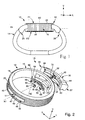
- FIG. 1 to 6 schematically shows a wristwatch 10 reversible housing 12 which is made according to the teachings of the invention.
- the housing 12 is provided to contain at least one watch movement (not shown) and associated display means (not shown). It is pivotally mounted, relative to a bracelet 14, about a longitudinal axis of pivoting A1, this longitudinal direction generally corresponding to the direction of the bracelet 14.
- elements will be qualified interior or exterior depending on their orientation relative to the housing 12.
- the housing 12 is constituted by a generally cylindrical middle part A2 of axis A2 which has an inner axial wall 18 and an outer peripheral axial wall 20.
- the middle part 16 is closed at one axial end, the upper end considering the figure 1 by a first cover 22 corresponding to the location face F1 of the wristwatch 10, and at the other axial end, the lower end considering the figure 1 by a second cover 24 corresponding to the reverse face F2 of the wristwatch 10.
- Each cover 22, 24 is made, for example, in the form of a transparent protective glass which allows an observer to see inside the housing 12, in particular to see the indications displayed by the display means .
- one of the covers 22, 24 may also be made differently from the other, especially in the form of a metal bottom.
- the bracelet 14 is fixed to the housing 12 by its two end strands 26, 28 which are diametrically opposite with respect to the axis A2 of the housing 12, along the pivot axis A1.
- each end strand 26, 28 comprises an insert 30 which is pivotally and slidably mounted on the housing 12, via a longitudinal pin 32.
- the bracelet 14 can be made, for example, under the shape of a leather or rubber band fixed on the inserts 30, for example by gluing, or in the form of a chain of metal links articulated on the inserts 30.
- each insert 30 generally has a parallelepipedal shape comprising, on the side of the housing 12, a concave curved inner face 34 complementary to the outer convex peripheral wall 20 of the housing 12 located vis-a-vis.
- Each end strand 26, 28 of the bracelet 14 comprises two horns 35, 37 which are fixed on the insert 30 and which give the watch a conventional appearance.
- Each insert 30 has, around its pivot axis A1, two indexed angular positions relative to the housing 12, which respectively correspond to two positions of use of the housing 12, that is to say a position at the location P1 in which face face F1 is oriented upwards, and a position upside down P2 in which the back face F2 is oriented upwards.
- Each insert 30 comprises, along its pivot axis A1, a longitudinal rest position Pr in which the insert 30 is pivotally locked by the interlocking of a male element 36 in a female element 38, and a longitudinal position of pivoting Pp in which the insert 30 is offset longitudinally outwards relative to the housing 12, and wherein the insert 30 is free to pivot relative to the housing 12.
- the male element 36 is formed integral with the housing 12 in the form of a rib 36 of substantially rectangular longitudinal section arranged on the outer peripheral wall 20 of the housing 12.
- the rib 36 thus forms a strip in excess thickness which follows the radius of curvature of the outer peripheral wall 20 of the housing 12.
- the female element 38 is formed as a groove 38 complementary to the rib 36 and arranged in the inner face 34 of the insert 30.
- the upper transverse edge 40 of the groove 38 is substantially adjacent to the upper transverse face 42 of the rib 36 and the lower transverse edge 44 of the groove 38 is substantially adjacent to the lower transverse face 46 of the rib 36 which prevents any pivoting of the insert 30 relative to the housing 12.
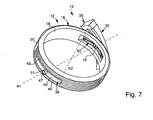
- the insert 30 In the pivoting position Pp, as shown in the Figures 5 to 7 , the insert 30 is offset longitudinally outwardly so that the rib 36 is disengaged from the groove 38 which allows the pivoting of the insert 30 relative to the housing 12.
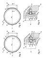
- the pin 32 extends here through the rib 36, in a longitudinal guide duct 47 which opens, on one side, into the inner wall 18 of the middle part 16 and, on the other side, into the outer transverse face. 49 of the rib 36 via a flange 51.
- each pin 32 comprises a first indexing element 48 which cooperates with a second indexing element 50 arranged on the housing 12 so as to index the associated insert 30 respectively in the rest position Pr and in pivoting position Pp.
- the trunnion 32 has, at its outer end, a longitudinal attachment section 52 which is fixed in the insert 30.
- the attachment section 52 is constituted here by a longitudinal threaded rod 52 which is screwed into a complementary threaded hole 54 formed in the insert 30.
- the trunnion 32 has, at its inner end, a cylindrical indexing section 48, which constitutes the first indexing element 48, and which extends longitudinally inside. of the housing 12.
- the indexing section 48 comprises two inner transverse notches 56 which are parallel and which are diametrically opposite in a vertical direction, with respect to the pivot axis A1, and two external transverse notches 58 which are parallel and diametrically opposed in a vertical direction, relative to the pivot axis A1.
- the two internal notches 56 are therefore offset longitudinally with respect to the two outer notches 58.
- An elastically deformable plate 60 is fixed to the middle part 16 inside the housing 12.
- the plate 60 extends generally in a transverse plane perpendicular to the longitudinal direction A1. It comprises a transverse slot 62 which delimits an upper blade 64 and a lower blade 66 designed to engage in the bottom of the notches 56, 58 of the indexing section 48 when the insert 30 occupies an indexed longitudinal position Pr, Pp.
- the blades 64, 66 therefore constitute the second indexing element 50 arranged on the housing 12.
- the upper and lower blades 64 and 64 are engaged in the outer notches 58 and, in the pivoting position, the 64, 66 blades are engaged in the inner slots 56.
- Each blade 64, 66 comprises, on the side of the transverse slot 62, a flat transverse edge 65, 67 which is provided to abut in the flat bottom of the associated notch 56, 58 in each indexed longitudinal position Pr, Pp.
- the transverse slot 62 is designed to open when the indexing section 48 of the pin 32 slides longitudinally between its two longitudinal positions Pr, Pp.
- the plate 60 deforms elastically, allowing the upper blade 64 and the lower blade 66 to deviate from each other.
- the plate 60 is fixed on the housing 12 by its transverse ends, here by means of two fixing screws 68. It is fixed in the bottom of an inner groove 70 which is arranged in the inner peripheral wall 18 of the middle part 16 and which thus constitutes a housing for the plate 60.
- the journal 32 comprises a cylindrical guide section 72 which extends at least partially inside the guide duct 47, whatever the indexed position occupied by the insert 30, and which is interposed between the section indexing 48 and the securing section 52.
- the journal 32 comprises an O-ring seal 74 which is mounted in a peripheral annular groove 76 interposed longitudinally between the indexing section 48 and the guide section 72.
- the outer diameter of the indexing section 48 and the outer diameter of the guide section 72 are substantially equal to the inner diameter of the guide duct 47 so as to guide the trunnion 32 in longitudinal sliding.
- a stop screw 78 is screwed to the outer axial end of the pin 32.
- the outer face 80 of the head of the stop screw 78 defines one side of each outer slot 56.
- the outer diameter of the the head of the stop screw 78 is greater than the outside diameter of the pin 32 which prevents the longitudinal sliding of the pin 32 outwards beyond its pivoting position Pp.
- the operation of the wristwatch 10 according to the invention is as follows. From the rest position Pr, represented on the figures 1 , 3 and 4 , the user draws longitudinally on each insert 30, holding the housing 12, so as to slide the pin 32 outwardly in its guide duct 47. Under stress longitudinal exerted by the pin 32 against the blades 64, 66, the blades 64, 66 deviate by elastic deformation and then return to their initial state of rest by engaging in the inner notches 56 associated, which corresponds to the longitudinal position of pivoting Pp shown on the Figures 5 and 6 .
- each notch 56, 58 of the indexing section 48 comprises, on the side of the notch 56, 58 opposite, an inclined wall 82, 84 forming a control surface which facilitates the deformation of the blades 64, 66.
- the groove 38 is disengaged from the rib 36 so that the insert 30 is no longer pivotally locked, which allows the user to rotate the housing 12 about its pivot axis A1 half a turn, from the angular position at the location P1 to the angular position upside down P2, by reversing the two faces F1, F2 of the housing 12 and presenting the upside-down face F2.
- the blades 64, 66 are elastically deformed again out of the internal notches 56, the maximum deformation corresponding to a quarter turn rotation, then they resume their original shape by engaging again in the notches internal 56 associated.
- An intermediate angular position between the position at the place P1 and the upside down position P2 is represented by way of example on the figure 7 .
- each insert 30 When the pivoting of a half turn is completed, the user pushes each insert 30 against the housing 12 by sliding the pin 32 axially inwards, in its guide duct 47, until the blades 64, 66 are received in the outer notches 58 and that the rib 36 engages in the groove 38, which corresponds to the rest position Pr of the insert 30.
- pivoting can here be carried out in both directions and the transition from the upside down position P2 to the position at the place P1 is carried out in the same manner as described above.
- the longitudinal indexing obtained through the indexing section 48 of the pin 32 and the deformable plate 60 is independent of the angular locking obtained by the engagement of the rib 36 in the groove 38.
- the manipulation of the housing 12 and inserts 30 is simplified, and the relative movements of each insert 30 relative to the housing 12 are more accurate and more reliable because they are perfectly defined by the cooperation of the indexing section 48 with the deformable plate 60.
- the cooperation of the indexing section 48 with the deformable plate 60 provides, in addition to the longitudinal indexing, an angular indexing.
- an angular indexing is felt by the user because of the elastic deformation of the blades 64, 66 which tends to return the pin 32 and the insert 30 to a stable angular position, that is to say either towards the position to the place P1, ie towards the position upside down P2.
Landscapes
- Physics & Mathematics (AREA)
- General Physics & Mathematics (AREA)
- Electric Clocks (AREA)
- Organic Low-Molecular-Weight Compounds And Preparation Thereof (AREA)
Claims (13)
- Armbanduhr (10) umfassend ein wenigstens ein Uhrwerk enthaltendes umkehrbares Gehäuse (12), in der jedes Bandende (26, 28) des Armbandes (14) einen Einsatz (30) umfasst, der über einen der Richtung (A1) des Armbandes (14) folgenden longitudinalen Drehzapfen (32) schwenk- und verschiebbar auf dem Gehäuse (12) montiert ist, und in der jeder Einsatz (30) wenigstens zwei indexierte Winkelpositionen (P1, P2) bezüglich des Gehäuses (12), die jeweils zwei Anwendungspositionen des Gehäuses (12) entsprechen, und wenigstens zwei longitudinale Positionen (Pr, Pp) umfasst, welches die Folgenden sind:- eine longitudinale Ruheposition (Pr), in der der Einsatz (30) durch die Einfügung eines Steckelements (36) in ein Aufnahmeelement (38) schwenkverriegelt ist, wobei eines der Elemente (36) auf dem Gehäuse (12) angeordnet ist und das andere Element (38) auf dem Einsatz (30) vorgesehen ist, und- eine longitudinale Schwenkposition (Pp), in der der Einsatz (30) relativ zum Gehäuse (12) längs nach aussen versetzt ist und in der der Einsatz (30) relativ zum Gehäuse (12) frei schwenkbar ist,dadurch gekennzeichnet, dass jeder Drehzapfen (32) ein erstes longitudinales Indexierungselement (48) umfasst, das mit einem auf dem Gehäuse (12) angeordneten zweiten longitudinalen Indexierungselement (64, 66) zusammenwirkt, um den zugeordneten Einsatz (30) in Ruheposition (Pr) bzw. in Schwenkposition (Pp) zu indexieren.
- Armbanduhr (10) nach vorhergehendem Anspruch, dadurch gekennzeichnet, dass der Drehzapfen (32) einen Befestigungsabschnitt (52), der im Einsatz (30) fixiert ist, und einen zylinderischen Indexiarungsabschnitt (48) umfasst, der sich längs zum Inneren des Gehäuses (12) erstreckt und der wenigstens eine erste und eine zweite Querkerbe (56, 58) umfasst, die längs versetzt sind und die mit wenigstens einer im Inneren des Gehäuses (12) befestigten elastisch verformbaren Lamelle (64, 66) durch Einfügung zusammenwirken, um den zugeordneten Einsatz (30) in Ruheposition (Pr) bzw. in Schwenkposition (Pp) zu indexieren.
- Armbanduhr (10) nach vorhergehendem Anspruch, dadurch gekennzeichnet, dass das Gehäuse (12) eine Platte (60) umfasst, die sich global in einer senkrecht zur längsrichtung (A1) liegenden Querebene erstreckt, dass die Platte (60) über ihre querliegenden Enden auf dem Gehäuse (12) befestigt ist und dass die Platte (60) einen Querschlitz (62) umfasst, der eine erste und eine zweite verformbare Lamelle (64, 66) begrenzt, wobei wenigstens eine Lamelle (64, 66) in einer der beiden Kerben (56, 58) aufgenommen wird, wenn der Einsatz (30) eine indexierte Position einnimmt.
- Armbanduhr (10) nach vorhergehendem Anspruch, dadurch gekennzeichnet, dass der bdexierungsabschnitt (48) für jede indexierte longitudinale Position (Pr, Pp) eine obere Kerbe (56, 58) und eine untere Kerbe (56. 58) umfasst, die diametral entgegengesetzt sind und die jeweils eine zugeordnete Lamelle (64, 66) empfangen, wenn der Einsatz (30) die entsprechende indexierte Position (Pr, Pp) einnimmt.
- Armbanduhr (10) nach Anspruch 3 oder 4, dadurch gekennzeichnet, dass die Platte (60) in einer Nut (70) befestigt ist, die auf der Innenseite (18) des Gehäusemittetteils (16) des Gehäuses (12) vorgesehen ist.
- Armbanduhr (10) nach einem der vorhergehenden Ansprüche, dadurch gekennzeichnet, dass das auf dem Gehäuse (12) ausgebildete Einfügungselement (36) für die Verriegelung des Einsatzes (30) einteilig mit dem Gehäuse (12) ausgeführt ist.
- Armbanduhr (10) nach vorhergehendem Anspruch, dadurch gekennzeichnet, dass das Steckelement (36) einteilig mit dem Gehäuse (12) in Form einer auf der peripheren Aussenseite (20) des Gehäuses (12) ausgebildeten Rippe (36) ausgebildet ist und dass das Aufnahmeelement (38) in Form einer ergänzenden Nut (38) ausgebildet ist, die auf der sich gegenüber dem Gehäuse (12) befindlichen Seite (34) des Einsatzes (30) ausgebildet ist.
- Armbanduhr (10) nach vorhergehendem Anspruch, dadurch gekennzeichnet, dass der Querschnitt der Rippe (36) merklich rechteckig ist.
- Armbanduhr (10) nach einem der vorhergehenden Ansprüche, dadurch gekennzeichnet, dass das Gehäuse (12) einen zylindrischen longitudinalen Führungskanal (47) umfasst, der einen Durchmesser aufweist, der merklich gleich wie der Aussendurchmesser des Drehzapfens (32) ist, und der den Drehzapfen (32) bei longitudinalem Verschieben führt.
- Armbanduhr (10) nach vorhergehendem Anspruch, dadurch gekenntzeichnet, dass der Drehzapfen (32) einen zylindrischen Führungsabschnitt (72) umfasst, der sich wenigstens teilweise im Inneren des Führungskanals (47) erstreckt, welches auch immer die vom Einsatz (30) eingenommene indexierte Position ist (Pr, Pp).
- Armbanduhr (10) nach vorhergehendem Anspruch, dadurch gekennzeichnet, dass der Drehzapfen (32) eine Dichtung (74) umfasst, die in einer längs zwischen dem Führungsabschnitt (72) und dem Indexierungsabschnitt (48) vorgesehenen peripheren ringförmigen Kehle (76) montiert ist.
- Armbanduhr (10) nach einem der Ansprüche 9 bis 11 kombiniert mit Anspruch 7, dadurch gekenntzeichnet, dass sich der Führungskanal (47) durch das Steckelement (36) hindurch erstreckt.
- Armbanduhr (10) nach einem der vorhergehenden Ansprüche, dadurch gekennzeichnet, dass jedes Bandende (26, 28) des Armbandes (14) zwei Hörner (35, 37) umfasst, die am Einsatz (30) befestigt sind.
Priority Applications (9)
| Application Number | Priority Date | Filing Date | Title |
|---|---|---|---|
| EP06120862A EP1902641B1 (de) | 2006-09-19 | 2006-09-19 | Zweiseitige Armbanduhr |
| AT06120862T ATE417521T1 (de) | 2006-09-19 | 2006-09-19 | Zweiseitige armbanduhr |
| DE602006004344T DE602006004344D1 (de) | 2006-09-19 | 2006-09-19 | Zweiseitige Armbanduhr |
| KR1020070090810A KR20080026034A (ko) | 2006-09-19 | 2007-09-07 | 리버시블 케이스를 포함하는 손목시계 |
| SG200706648-3A SG141345A1 (en) | 2006-09-19 | 2007-09-07 | Wristwatch with a reversible case |
| JP2007239212A JP5032925B2 (ja) | 2006-09-19 | 2007-09-14 | 回転可能なケースを有する腕時計 |
| CN200710152865XA CN101149590B (zh) | 2006-09-19 | 2007-09-18 | 带有可反转表壳的手表 |
| US11/857,749 US7507017B2 (en) | 2006-09-19 | 2007-09-19 | Wristwatch with a reversible case |
| HK08110136.6A HK1118913B (en) | 2006-09-19 | 2008-09-11 | Wristwatch with a reversible case |
Applications Claiming Priority (1)
| Application Number | Priority Date | Filing Date | Title |
|---|---|---|---|
| EP06120862A EP1902641B1 (de) | 2006-09-19 | 2006-09-19 | Zweiseitige Armbanduhr |
Publications (2)
| Publication Number | Publication Date |
|---|---|
| EP1902641A1 EP1902641A1 (de) | 2008-03-26 |
| EP1902641B1 true EP1902641B1 (de) | 2008-12-17 |
Family
ID=37890411
Family Applications (1)
| Application Number | Title | Priority Date | Filing Date |
|---|---|---|---|
| EP06120862A Active EP1902641B1 (de) | 2006-09-19 | 2006-09-19 | Zweiseitige Armbanduhr |
Country Status (8)
| Country | Link |
|---|---|
| US (1) | US7507017B2 (de) |
| EP (1) | EP1902641B1 (de) |
| JP (1) | JP5032925B2 (de) |
| KR (1) | KR20080026034A (de) |
| CN (1) | CN101149590B (de) |
| AT (1) | ATE417521T1 (de) |
| DE (1) | DE602006004344D1 (de) |
| SG (1) | SG141345A1 (de) |
Families Citing this family (18)
| Publication number | Priority date | Publication date | Assignee | Title |
|---|---|---|---|---|
| EP2188676B1 (de) * | 2007-09-04 | 2013-11-06 | Dominique Loiseau | Armbanduhr mit einer reversibilitätseinrichtung |
| WO2010032084A1 (fr) * | 2008-09-19 | 2010-03-25 | Dominique Loiseau | Montre-bracelet reversible |
| RU2447472C1 (ru) * | 2010-11-26 | 2012-04-10 | Общество С Ограниченной Ответственностью "Часовой Завод Ника" | Часы с переворачиваемой капсулой с часовым механизмом, модуль с часовым механизмом, капсула с часовым механизмом и корпус часов |
| EP2487548B1 (de) * | 2011-02-11 | 2018-01-10 | Montres Breguet SA | Umkehrmechanismus der Drehbewegung eines Gehäuses |
| USD656846S1 (en) * | 2011-10-21 | 2012-04-03 | Paul Kweton | Watch |
| CN102548302B (zh) * | 2011-12-20 | 2015-03-11 | 鸿富锦精密工业(深圳)有限公司 | 腕戴式电子装置 |
| EP2789254A1 (de) * | 2013-04-12 | 2014-10-15 | Montres Jaquet Droz SA | Ergonomisches Armband für Armbanduhr oder Schmuckstück |
| USD721609S1 (en) * | 2014-01-06 | 2015-01-27 | JayBird LLC | Wristband |
| US9314071B2 (en) * | 2014-04-15 | 2016-04-19 | Roberto Rivera | Universal reversible watch band device |
| TW201544035A (zh) * | 2014-05-28 | 2015-12-01 | Pegatron Corp | 穿戴式裝置 |
| CH711611A1 (en) | 2015-10-06 | 2017-04-13 | Tag Heuer - Swiss Mft Sa | Watch case with removable horns. |
| WO2017060842A1 (fr) | 2015-10-06 | 2017-04-13 | Lvmh Swiss Manufactures Sa | Boite de montre comportant des cornes amovibles |
| CN108885429B (zh) | 2016-02-12 | 2020-10-30 | P·拉菲 | 具有在多种构造的可翻转腕表 |
| US9639058B1 (en) | 2016-03-17 | 2017-05-02 | Fossil Group, Inc. | Timepiece with movable case |
| CH712446A1 (fr) | 2016-05-10 | 2017-11-15 | Lvmh Swiss Mft Sa | Boîte de montre comportant des cornes amovibles et procédé d'assemblage d'un bracelet sur une telle boîte de montre. |
| US11467541B2 (en) * | 2020-03-11 | 2022-10-11 | Jun-Liang Guo | Watch with double watch-surface and method for disassembling same |
| WO2023092263A1 (zh) * | 2021-11-23 | 2023-06-01 | 陈志强 | 一种可以旋转的手表表带连接结构 |
| KR102782074B1 (ko) * | 2022-10-04 | 2025-03-13 | 김영덕 | 스마트워치 착용 기어 |
Family Cites Families (15)
| Publication number | Priority date | Publication date | Assignee | Title |
|---|---|---|---|---|
| US1930416A (en) * | 1931-03-04 | 1933-10-10 | Chauvot Rene Alfred | Sliding and pivoting wristlet watch |
| CH172421A (fr) * | 1934-01-05 | 1934-10-15 | Movado Montres | Montre-bracelet. |
| US4236239A (en) * | 1979-07-06 | 1980-11-25 | Societe Suisse Pour L'industrie Horlogere Management Services S.A. | Electronic timepiece comprising two different displays |
| CH640688GA3 (fr) * | 1980-10-27 | 1984-01-31 | Eterna Sa | Montre a mouvement electronique et a deux moyens d'affichage. |
| CH646569GA3 (de) * | 1982-05-11 | 1984-12-14 | ||
| AT379736B (de) * | 1984-02-15 | 1986-02-25 | Hirsch Hermann Leder Kunstst | Anschlussteil fuer riemen |
| CH659167GA3 (en) * | 1985-05-29 | 1987-01-15 | Dual-face wrist watch | |
| EP1070997A1 (de) * | 1999-07-22 | 2001-01-24 | The Swatch Group Management Services AG | Umkehrbare Armbanduhr |
| CH696091A5 (fr) * | 2000-09-14 | 2006-12-15 | Swatch Group Man Serv Ag | Montre-bracelet à boîtier réversible. |
| CH696090A5 (fr) * | 2000-09-14 | 2006-12-15 | Swatch Group Man Serv Ag | Montre-bracelet à boîtier réversible. |
| CH695299A5 (fr) * | 2002-12-12 | 2006-03-15 | Eric Bouille | Ensemble formé d'un support et d'un objet fixés l'un à l'autre de manière amovible, notamment formé d'une montre et d'un bracelet. |
| EP1437635B1 (de) * | 2003-01-08 | 2006-11-02 | Jonathan M. Strauss | Uhrgehäuse |
| EP1604249A2 (de) * | 2003-03-14 | 2005-12-14 | Voltige S.A. | Vorrichtung zu dem umkippen und der austauschbarkeit einer uhr relativ zu einem träger |
| EP1609027B9 (de) * | 2003-03-31 | 2008-10-08 | TAG Heuer SA | Umkehrbare uhr |
| US20050249051A1 (en) * | 2004-03-24 | 2005-11-10 | Philippe Cogoli | Timepiece |
-
2006
- 2006-09-19 DE DE602006004344T patent/DE602006004344D1/de active Active
- 2006-09-19 AT AT06120862T patent/ATE417521T1/de not_active IP Right Cessation
- 2006-09-19 EP EP06120862A patent/EP1902641B1/de active Active
-
2007
- 2007-09-07 KR KR1020070090810A patent/KR20080026034A/ko not_active Withdrawn
- 2007-09-07 SG SG200706648-3A patent/SG141345A1/en unknown
- 2007-09-14 JP JP2007239212A patent/JP5032925B2/ja active Active
- 2007-09-18 CN CN200710152865XA patent/CN101149590B/zh active Active
- 2007-09-19 US US11/857,749 patent/US7507017B2/en active Active
Also Published As
| Publication number | Publication date |
|---|---|
| EP1902641A1 (de) | 2008-03-26 |
| SG141345A1 (en) | 2008-04-28 |
| US20080068933A1 (en) | 2008-03-20 |
| CN101149590A (zh) | 2008-03-26 |
| HK1118913A1 (en) | 2009-02-20 |
| JP2008076392A (ja) | 2008-04-03 |
| DE602006004344D1 (de) | 2009-01-29 |
| US7507017B2 (en) | 2009-03-24 |
| CN101149590B (zh) | 2010-12-08 |
| KR20080026034A (ko) | 2008-03-24 |
| ATE417521T1 (de) | 2009-01-15 |
| JP5032925B2 (ja) | 2012-09-26 |
Similar Documents
| Publication | Publication Date | Title |
|---|---|---|
| EP1902641B1 (de) | Zweiseitige Armbanduhr | |
| EP1790247B1 (de) | Einrichtung zum Verstellen der Länge eines Armbandes, Armband mit einer solchen Einrichtung, und Uhr ausgerüstet mit einem solchen Armband | |
| EP3756501B1 (de) | Befestigungsvorrichtung für armband | |
| EP2322997B1 (de) | Tragbares Objekt mit austauschbarem Armband | |
| WO2008064931A1 (fr) | Fermoir de bracelet avec dispositif de reglage de longueur | |
| EP3422118B1 (de) | Vorrichtung zum befestigen eines armbands | |
| EP1564607B1 (de) | Vorrichtung zum Kroneschütz für eine Uhr | |
| EP3674815A1 (de) | Armbanduhrengehäuse, das mit einem kreisförmigen ring ausgestattet ist, und armbanduhr sowie montagekit für ein uhrenarmband, das dieses umfasst | |
| EP4176755A1 (de) | Anbringung eines faserstrangs eines armbands an einem armbanduhrgehäuse | |
| EP3825784A1 (de) | Befestigungsvorrichtung für armband | |
| EP0855866B1 (de) | Verschluss mit knopf | |
| CH694393A5 (fr) | Dispositif de fixation de l'extrémité d'un bracelet au boîtier d'une montre. | |
| WO2011027041A1 (fr) | Lunettes pourvues d'un manchon de decoration rotatif | |
| CH715003B1 (fr) | Système d'attache d'un bracelet à une boîte de montre. | |
| CH713724B1 (fr) | Dispositif de fixation d'un bracelet à une boîte de montre. | |
| EP1785784A2 (de) | Vorrichtung zur Verbindung eines Uhrarmbands | |
| EP3569090B1 (de) | Befestigungssystem eines armbands an einem armbanduhrgehäuse | |
| WO2023078836A1 (fr) | Assemblage d'un brin de bracelet sur une boîte de montre | |
| EP3599930B1 (de) | Faltschnallenverschluss | |
| EP3219220B1 (de) | Armband mit längeneinstellungsvorrichtung | |
| EP4733855A1 (de) | Uhrmechanismus mit einer positionsauswahlvorrichtung eines funktionsorgans | |
| CH716349A2 (fr) | Dispositif de fixation d'un bracelet. | |
| EP4541222A1 (de) | Faltverschluss für armband, insbesondere für armbanduhren | |
| WO2023170128A1 (fr) | Fermoir a boucle deployante | |
| CH713974A2 (fr) | Dispositif de liaison mécanique pour composants d'habillage horloger, notamment en forme de barrette de fixation. |
Legal Events
| Date | Code | Title | Description |
|---|---|---|---|
| PUAI | Public reference made under article 153(3) epc to a published international application that has entered the european phase |
Free format text: ORIGINAL CODE: 0009012 |
|
| 17P | Request for examination filed |
Effective date: 20070605 |
|
| AK | Designated contracting states |
Kind code of ref document: A1 Designated state(s): AT BE BG CH CY CZ DE DK EE ES FI FR GB GR HU IE IS IT LI LT LU LV MC NL PL PT RO SE SI SK TR |
|
| AX | Request for extension of the european patent |
Extension state: AL BA HR MK YU |
|
| GRAP | Despatch of communication of intention to grant a patent |
Free format text: ORIGINAL CODE: EPIDOSNIGR1 |
|
| GRAS | Grant fee paid |
Free format text: ORIGINAL CODE: EPIDOSNIGR3 |
|
| GRAA | (expected) grant |
Free format text: ORIGINAL CODE: 0009210 |
|
| AKX | Designation fees paid |
Designated state(s): AT BE BG CH CY CZ DE DK EE ES FI FR GB GR HU IE IS IT LI LT LU LV MC NL PL PT RO SE SI SK TR |
|
| AXX | Extension fees paid |
Extension state: MK Payment date: 20080926 Extension state: RS Payment date: 20080926 Extension state: HR Payment date: 20080926 Extension state: BA Payment date: 20080926 Extension state: AL Payment date: 20080926 |
|
| AK | Designated contracting states |
Kind code of ref document: B1 Designated state(s): AT BE BG CH CY CZ DE DK EE ES FI FR GB GR HU IE IS IT LI LT LU LV MC NL PL PT RO SE SI SK TR |
|
| AX | Request for extension of the european patent |
Extension state: AL BA HR MK RS |
|
| REG | Reference to a national code |
Ref country code: GB Ref legal event code: FG4D Free format text: NOT ENGLISH |
|
| REG | Reference to a national code |
Ref country code: CH Ref legal event code: EP |
|
| REG | Reference to a national code |
Ref country code: IE Ref legal event code: FG4D Free format text: LANGUAGE OF EP DOCUMENT: FRENCH |
|
| REF | Corresponds to: |
Ref document number: 602006004344 Country of ref document: DE Date of ref document: 20090129 Kind code of ref document: P |
|
| REG | Reference to a national code |
Ref country code: CH Ref legal event code: NV Representative=s name: ICB INGENIEURS CONSEILS EN BREVETS SA |
|
| PG25 | Lapsed in a contracting state [announced via postgrant information from national office to epo] |
Ref country code: LT Free format text: LAPSE BECAUSE OF FAILURE TO SUBMIT A TRANSLATION OF THE DESCRIPTION OR TO PAY THE FEE WITHIN THE PRESCRIBED TIME-LIMIT Effective date: 20081217 |
|
| PG25 | Lapsed in a contracting state [announced via postgrant information from national office to epo] |
Ref country code: LV Free format text: LAPSE BECAUSE OF FAILURE TO SUBMIT A TRANSLATION OF THE DESCRIPTION OR TO PAY THE FEE WITHIN THE PRESCRIBED TIME-LIMIT Effective date: 20081217 Ref country code: SI Free format text: LAPSE BECAUSE OF FAILURE TO SUBMIT A TRANSLATION OF THE DESCRIPTION OR TO PAY THE FEE WITHIN THE PRESCRIBED TIME-LIMIT Effective date: 20081217 Ref country code: FI Free format text: LAPSE BECAUSE OF FAILURE TO SUBMIT A TRANSLATION OF THE DESCRIPTION OR TO PAY THE FEE WITHIN THE PRESCRIBED TIME-LIMIT Effective date: 20081217 Ref country code: PL Free format text: LAPSE BECAUSE OF FAILURE TO SUBMIT A TRANSLATION OF THE DESCRIPTION OR TO PAY THE FEE WITHIN THE PRESCRIBED TIME-LIMIT Effective date: 20081217 Ref country code: NL Free format text: LAPSE BECAUSE OF FAILURE TO SUBMIT A TRANSLATION OF THE DESCRIPTION OR TO PAY THE FEE WITHIN THE PRESCRIBED TIME-LIMIT Effective date: 20081217 |
|
| NLV1 | Nl: lapsed or annulled due to failure to fulfill the requirements of art. 29p and 29m of the patents act | ||
| REG | Reference to a national code |
Ref country code: IE Ref legal event code: FD4D |
|
| PG25 | Lapsed in a contracting state [announced via postgrant information from national office to epo] |
Ref country code: IE Free format text: LAPSE BECAUSE OF FAILURE TO SUBMIT A TRANSLATION OF THE DESCRIPTION OR TO PAY THE FEE WITHIN THE PRESCRIBED TIME-LIMIT Effective date: 20081217 Ref country code: RO Free format text: LAPSE BECAUSE OF FAILURE TO SUBMIT A TRANSLATION OF THE DESCRIPTION OR TO PAY THE FEE WITHIN THE PRESCRIBED TIME-LIMIT Effective date: 20081217 Ref country code: EE Free format text: LAPSE BECAUSE OF FAILURE TO SUBMIT A TRANSLATION OF THE DESCRIPTION OR TO PAY THE FEE WITHIN THE PRESCRIBED TIME-LIMIT Effective date: 20081217 Ref country code: ES Free format text: LAPSE BECAUSE OF FAILURE TO SUBMIT A TRANSLATION OF THE DESCRIPTION OR TO PAY THE FEE WITHIN THE PRESCRIBED TIME-LIMIT Effective date: 20090328 Ref country code: BG Free format text: LAPSE BECAUSE OF FAILURE TO SUBMIT A TRANSLATION OF THE DESCRIPTION OR TO PAY THE FEE WITHIN THE PRESCRIBED TIME-LIMIT Effective date: 20090317 |
|
| PG25 | Lapsed in a contracting state [announced via postgrant information from national office to epo] |
Ref country code: CZ Free format text: LAPSE BECAUSE OF FAILURE TO SUBMIT A TRANSLATION OF THE DESCRIPTION OR TO PAY THE FEE WITHIN THE PRESCRIBED TIME-LIMIT Effective date: 20081217 Ref country code: IS Free format text: LAPSE BECAUSE OF FAILURE TO SUBMIT A TRANSLATION OF THE DESCRIPTION OR TO PAY THE FEE WITHIN THE PRESCRIBED TIME-LIMIT Effective date: 20090417 Ref country code: SE Free format text: LAPSE BECAUSE OF FAILURE TO SUBMIT A TRANSLATION OF THE DESCRIPTION OR TO PAY THE FEE WITHIN THE PRESCRIBED TIME-LIMIT Effective date: 20090317 Ref country code: PT Free format text: LAPSE BECAUSE OF FAILURE TO SUBMIT A TRANSLATION OF THE DESCRIPTION OR TO PAY THE FEE WITHIN THE PRESCRIBED TIME-LIMIT Effective date: 20090518 Ref country code: AT Free format text: LAPSE BECAUSE OF FAILURE TO SUBMIT A TRANSLATION OF THE DESCRIPTION OR TO PAY THE FEE WITHIN THE PRESCRIBED TIME-LIMIT Effective date: 20081217 |
|
| PG25 | Lapsed in a contracting state [announced via postgrant information from national office to epo] |
Ref country code: SK Free format text: LAPSE BECAUSE OF FAILURE TO SUBMIT A TRANSLATION OF THE DESCRIPTION OR TO PAY THE FEE WITHIN THE PRESCRIBED TIME-LIMIT Effective date: 20081217 |
|
| PLBE | No opposition filed within time limit |
Free format text: ORIGINAL CODE: 0009261 |
|
| STAA | Information on the status of an ep patent application or granted ep patent |
Free format text: STATUS: NO OPPOSITION FILED WITHIN TIME LIMIT |
|
| PG25 | Lapsed in a contracting state [announced via postgrant information from national office to epo] |
Ref country code: DK Free format text: LAPSE BECAUSE OF FAILURE TO SUBMIT A TRANSLATION OF THE DESCRIPTION OR TO PAY THE FEE WITHIN THE PRESCRIBED TIME-LIMIT Effective date: 20081217 |
|
| 26N | No opposition filed |
Effective date: 20090918 |
|
| BERE | Be: lapsed |
Owner name: MONTRES BREGUET S.A. Effective date: 20090930 |
|
| PG25 | Lapsed in a contracting state [announced via postgrant information from national office to epo] |
Ref country code: MC Free format text: LAPSE BECAUSE OF NON-PAYMENT OF DUE FEES Effective date: 20090930 |
|
| PG25 | Lapsed in a contracting state [announced via postgrant information from national office to epo] |
Ref country code: BE Free format text: LAPSE BECAUSE OF NON-PAYMENT OF DUE FEES Effective date: 20090930 |
|
| PG25 | Lapsed in a contracting state [announced via postgrant information from national office to epo] |
Ref country code: GR Free format text: LAPSE BECAUSE OF FAILURE TO SUBMIT A TRANSLATION OF THE DESCRIPTION OR TO PAY THE FEE WITHIN THE PRESCRIBED TIME-LIMIT Effective date: 20090318 |
|
| PG25 | Lapsed in a contracting state [announced via postgrant information from national office to epo] |
Ref country code: LU Free format text: LAPSE BECAUSE OF NON-PAYMENT OF DUE FEES Effective date: 20090919 |
|
| PG25 | Lapsed in a contracting state [announced via postgrant information from national office to epo] |
Ref country code: HU Free format text: LAPSE BECAUSE OF FAILURE TO SUBMIT A TRANSLATION OF THE DESCRIPTION OR TO PAY THE FEE WITHIN THE PRESCRIBED TIME-LIMIT Effective date: 20090618 |
|
| PG25 | Lapsed in a contracting state [announced via postgrant information from national office to epo] |
Ref country code: TR Free format text: LAPSE BECAUSE OF FAILURE TO SUBMIT A TRANSLATION OF THE DESCRIPTION OR TO PAY THE FEE WITHIN THE PRESCRIBED TIME-LIMIT Effective date: 20081217 |
|
| PG25 | Lapsed in a contracting state [announced via postgrant information from national office to epo] |
Ref country code: CY Free format text: LAPSE BECAUSE OF FAILURE TO SUBMIT A TRANSLATION OF THE DESCRIPTION OR TO PAY THE FEE WITHIN THE PRESCRIBED TIME-LIMIT Effective date: 20081217 |
|
| REG | Reference to a national code |
Ref country code: FR Ref legal event code: PLFP Year of fee payment: 10 |
|
| REG | Reference to a national code |
Ref country code: FR Ref legal event code: PLFP Year of fee payment: 11 |
|
| REG | Reference to a national code |
Ref country code: FR Ref legal event code: PLFP Year of fee payment: 12 |
|
| REG | Reference to a national code |
Ref country code: FR Ref legal event code: PLFP Year of fee payment: 13 |
|
| P01 | Opt-out of the competence of the unified patent court (upc) registered |
Effective date: 20230611 |
|
| REG | Reference to a national code |
Ref country code: DE Ref legal event code: R082 Ref document number: 602006004344 Country of ref document: DE Representative=s name: PATENTANWAELTE STURM WEILNAU FRANKE PARTNERSCH, DE |
|
| REG | Reference to a national code |
Ref country code: CH Ref legal event code: U11 Free format text: ST27 STATUS EVENT CODE: U-0-0-U10-U11 (AS PROVIDED BY THE NATIONAL OFFICE) Effective date: 20251001 |
|
| PGFP | Annual fee paid to national office [announced via postgrant information from national office to epo] |
Ref country code: DE Payment date: 20250820 Year of fee payment: 20 |
|
| PGFP | Annual fee paid to national office [announced via postgrant information from national office to epo] |
Ref country code: IT Payment date: 20250820 Year of fee payment: 20 |
|
| PGFP | Annual fee paid to national office [announced via postgrant information from national office to epo] |
Ref country code: GB Payment date: 20250820 Year of fee payment: 20 |
|
| PGFP | Annual fee paid to national office [announced via postgrant information from national office to epo] |
Ref country code: FR Payment date: 20250820 Year of fee payment: 20 |
|
| PGFP | Annual fee paid to national office [announced via postgrant information from national office to epo] |
Ref country code: CH Payment date: 20251001 Year of fee payment: 20 |