EP1902805A2 - Outil pour le traitement d'une pièce à usiner - Google Patents
Outil pour le traitement d'une pièce à usiner Download PDFInfo
- Publication number
- EP1902805A2 EP1902805A2 EP07014752A EP07014752A EP1902805A2 EP 1902805 A2 EP1902805 A2 EP 1902805A2 EP 07014752 A EP07014752 A EP 07014752A EP 07014752 A EP07014752 A EP 07014752A EP 1902805 A2 EP1902805 A2 EP 1902805A2
- Authority
- EP
- European Patent Office
- Prior art keywords
- tool
- threads
- region
- cutting edge
- flute
- Prior art date
- Legal status (The legal status is an assumption and is not a legal conclusion. Google has not performed a legal analysis and makes no representation as to the accuracy of the status listed.)
- Granted
Links
Images


Classifications
-
- B—PERFORMING OPERATIONS; TRANSPORTING
- B23—MACHINE TOOLS; METAL-WORKING NOT OTHERWISE PROVIDED FOR
- B23G—THREAD CUTTING; WORKING OF SCREWS, BOLT HEADS, OR NUTS, IN CONJUNCTION THEREWITH
- B23G5/00—Thread-cutting tools; Die-heads
- B23G5/02—Thread-cutting tools; Die-heads without means for adjustment
- B23G5/06—Taps
-
- B—PERFORMING OPERATIONS; TRANSPORTING
- B23—MACHINE TOOLS; METAL-WORKING NOT OTHERWISE PROVIDED FOR
- B23G—THREAD CUTTING; WORKING OF SCREWS, BOLT HEADS, OR NUTS, IN CONJUNCTION THEREWITH
- B23G2200/00—Details of threading tools
- B23G2200/04—Tools with negative cutting angles
-
- B—PERFORMING OPERATIONS; TRANSPORTING
- B23—MACHINE TOOLS; METAL-WORKING NOT OTHERWISE PROVIDED FOR
- B23G—THREAD CUTTING; WORKING OF SCREWS, BOLT HEADS, OR NUTS, IN CONJUNCTION THEREWITH
- B23G2200/00—Details of threading tools
- B23G2200/48—Spiral grooves, i.e. spiral flutes
-
- B—PERFORMING OPERATIONS; TRANSPORTING
- B23—MACHINE TOOLS; METAL-WORKING NOT OTHERWISE PROVIDED FOR
- B23G—THREAD CUTTING; WORKING OF SCREWS, BOLT HEADS, OR NUTS, IN CONJUNCTION THEREWITH
- B23G2210/00—Details of threads produced
- B23G2210/04—Internal threads
-
- B—PERFORMING OPERATIONS; TRANSPORTING
- B23—MACHINE TOOLS; METAL-WORKING NOT OTHERWISE PROVIDED FOR
- B23G—THREAD CUTTING; WORKING OF SCREWS, BOLT HEADS, OR NUTS, IN CONJUNCTION THEREWITH
- B23G2210/00—Details of threads produced
- B23G2210/16—Multiple start threads
-
- Y—GENERAL TAGGING OF NEW TECHNOLOGICAL DEVELOPMENTS; GENERAL TAGGING OF CROSS-SECTIONAL TECHNOLOGIES SPANNING OVER SEVERAL SECTIONS OF THE IPC; TECHNICAL SUBJECTS COVERED BY FORMER USPC CROSS-REFERENCE ART COLLECTIONS [XRACs] AND DIGESTS
- Y10—TECHNICAL SUBJECTS COVERED BY FORMER USPC
- Y10T—TECHNICAL SUBJECTS COVERED BY FORMER US CLASSIFICATION
- Y10T408/00—Cutting by use of rotating axially moving tool
- Y10T408/86—Tool-support with means to permit positioning of the Tool relative to support
- Y10T408/87—Tool having stepped cutting edges
- Y10T408/8725—Tool having stepped cutting edges including means to permit relative axial positioning of edges
- Y10T408/8734—Tool having stepped cutting edges including means to permit relative axial positioning of edges including central Tool axially movable relative to support
-
- Y—GENERAL TAGGING OF NEW TECHNOLOGICAL DEVELOPMENTS; GENERAL TAGGING OF CROSS-SECTIONAL TECHNOLOGIES SPANNING OVER SEVERAL SECTIONS OF THE IPC; TECHNICAL SUBJECTS COVERED BY FORMER USPC CROSS-REFERENCE ART COLLECTIONS [XRACs] AND DIGESTS
- Y10—TECHNICAL SUBJECTS COVERED BY FORMER USPC
- Y10T—TECHNICAL SUBJECTS COVERED BY FORMER US CLASSIFICATION
- Y10T408/00—Cutting by use of rotating axially moving tool
- Y10T408/89—Tool or Tool with support
- Y10T408/904—Tool or Tool with support with pitch-stabilizing ridge
- Y10T408/9048—Extending outwardly from tool-axis
Definitions
- the invention relates to a tool for machining a workpiece, which tool is rotatable about a tool axis, comprising a tool shank and a tool head.
- the tool head has at least one cutting edge, at least one scraping gate and at least one flute.
- a tool may be, for example, a tap, as in the DE 83 24 835 U1 is described.
- the tap from the DE 83 24 835 U1 has in its shaft part three evenly distributed over the circumference arranged axially parallel dirt grooves, between which teeth supporting webs are arranged.
- On the head side in the gate area of the tap this is conically formed by a portion of the tips of the teeth.
- peeling cutout grooves are arranged, which merge with their rear ends in the straight groove grooves and are directed towards the front side of the tap down.
- forwardly tapered webs are formed, which carry a cutting edge.
- Such taps with a Hälanschnitt are particularly suitable for threading in through holes.
- the chips are applied in the cutting direction, so that they fall out of the well and prevent the cutting process by a chip jam.
- the invention has for its object to provide a tool of the type mentioned above such that the cutting performance of the tool is as good as possible.
- a tool for machining a workpiece which tool is rotatable about a tool axis, comprising a tool shank and a tool head, which tool head at least one cutting edge, at least one of the cutting edge associated, substantially in the direction of the tool axis extending Schwarzlanterrorism and at least one of the cutting edge associated, extending substantially in the direction of the tool axis flute, wherein the flute has a left twist and the Schwarzlan plinth is skewed to the left or wherein the flute has a Georgiadrall and the Schlan plinth is right-oblique.
- the scraper neck goes over into the flute.
- a tool with a cutting edge, a cutting edge and a flute which includes a left-hand twist and whose associated blade is skewed to the left or which includes a right-hand twist and whose Schwarzrough is right-angled, has good cutting properties.
- a right-hand thread is machined when the flute includes a left-hand twist and its associated Schwarzlanterrorism is skewed left, or a left-hand thread is processed when the flute includes a right-hand twist and their associated Schwarzieri is right-oblique.
- Such a tool shows good performance and has been found particularly advantageous in the through hole machining of steels with higher strength and for machining through holes at high speed, wherein the tool is rotated about its tool axis.
- the tool for machining of tempered steels, nitriding steels, hot working steels, hardened steels, cold work steels, case hardening steels and / or alloyed steels eg 42CrMo4V with a tensile strength R m of about 1000 N / mm 2 or C45 with a tensile strength R m of approx. 600 N / mm 2 , to be used.
- the cutting speed v c is about 5 to 50 m / min, preferably 10 m / min, and in the processing of C45 about 10 to 100 m / min, preferably 20 m / min.
- the tool is thus preferably operated in a cutting speed range of about 5 to 100 m / min.
- the peeling gate By means of the peeling gate, the chips produced during the cutting process are thereby applied to the front from a through hole.
- the left-handed flute serves for axial chip removal.
- the helix angle of the left-hand twist or the right-hand spiral of the flute is between 2 ° and 15 °, preferably 5 ° to 7 °, relative to the tool axis of the tool.
- the Schlanußschräge the Schilanußs is between 5 ° and 20 °, preferably 8 ° to 12 °, and the Schwarzne Trent the Schilanitess between 3 ° and 15 °, preferably 8 ° to 10 °.
- the peel angle and the peel angle are also indicated on the tool axis of the tool.
- the skiving crop bevel is skewed to the left or skewed to the right in relation to the tool axis.
- the cutting edge of the tool comprises a peripheral cutting edge.
- the rake angle of the peripheral edge to the skiving gate or to the flute with respect to the tangent to the cutting edge of the peripheral cutting edge in the cutting direction is between + 30 ° and -5 °.
- the rake angle can vary between different designs of the tool.
- the rake angle of the peripheral cutting edge changes starting from the end face on the tool head in the direction of the tool shank.
- the rake angle can vary with respect to a specific measuring point on the tool. The rake angle can therefore change differently in the case of different embodiments of the tool, starting from the end face on the tool head in the direction of the tool shank.
- the rake angle varies continuously in the specified range of + 30 ° and -5 ° from the end face of the tool head to the end of the skiving gate, wherein both the initial value and the final value are variable.
- the rake angle can change, but does not necessarily change.
- the rake angle according to a variant of the invention has a final value between + 30 ° and -5 °, preferably between + 15 ° and -5 °.
- the length of the peel of the tool is between about one fifth (1/5) to three quarters (3/4) of the length of the flute, d. H. If the flute were to be measured from the end face of the tool to its end on the tool head, the coulter cut extends over approximately one-fifth to three-quarters of the length of the flute starting from the end face of the tool on which the coulter cut begins.
- the core diameter of the tool increases toward the tool shank.
- the cross-sectional area of the cutting edge also increases, starting from the end face of the tool head in the direction of the tool shank, wherein the tooth width of the cutting edge preferably also increases.
- the tool has a plurality of cutting edges, for example three, four, five or more cutting edges and that the tool is a tapping tool which comprises a helically running external thread.
- the external thread is arranged on the cutting edges or the peripheral cutting edges of the cutting edges, which are separated from one another by the peeling sections and flutes. If the tool has a flute with a left twist and a coulter cut, which is inclined to the left, this tool is preferably intended for the production of right-hand threads. If, on the other hand, the tool has a flute with a right-hand twist and a coulter-cut which is right-angled, then this tool is preferably provided for the production of left-hand threads.
- the threads of the external thread are flattened and in a subsequent to the first region of the second region of the tool head full threads available, including a thread without Flattening is understood, which may well be interrupted by Schlanismee or flutes.
- the flattening of the threads in the first region decreases starting from the end face of the tool head to the second region.
- the tool has a subsequent to the second region third range of threads of the tool head, in which the threads are also flattened.
- the flattening of the threads in the third region increases starting from the second region in the direction of the tool shank.
- the second region of the threads starts approximately in the region of the end of the Schlanterrorisms, in the preferred three to nine threads, which, as already mentioned, are flattened, are present.
- the second area follows the gate.
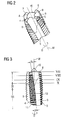
- the tapping tool 1 shows a tool according to the invention for the machining of a workpiece, which is a tapping tool 1 in the case of the present exemplary embodiment.
- the tapping tool 1 comprises a tool shank 2 for clamping into a machine tool and a tool head 3.
- the tool shank 2 merges into the tool head 3 via a phase P.
- the tapping tool 1 comprises a tool axis in the form of a central axis M about which the tapping tool 1 is rotatable.
- FIGS. 2 and 3 show part of the tool head 3 of the tapping tool 1 from FIG.
- FIGS. 2 and 3 show part of the tool head 3 of the tapping tool 1 from FIG.
- the tapping tool 1 is designed such that the flutes 9 and the cutting edges 4 to 7 have a left-hand twist with respect to the tool center axis M.
- the helix angle ⁇ of a flute 9 is entered as an example in FIG.
- the helix angle ⁇ of a flute 9 may be in the tapping tool 1 between 2 ° and 15 ° and is given in relation to the central axis M of the tapping tool 1.
- the helix angle ⁇ is about 5 ° to 7 °.
- the helix angle ⁇ is chosen equal in the case of the present embodiment in all flutes 9.
- the tapping tool 1 is configured in such a way that the peeling sections 8 each have a peel angle ⁇ A of between 5 ° and 20 °, preferably approximately 8 ° to 12 ° with respect to the central axis M of the tapping tool 1 have.
- the peeling leading bevel ⁇ A is chosen to be the same for all peeling sections 8 and is likewise indicated with respect to the center axis M of the tapping tool 1 (see FIG.
- the Schwarzlanismeschräge is left skew in the case of the present embodiment in cooperation with a left-tipped flute 9.
- the tapping tool is preferably provided for the production of right-hand threads.
- the peel angle ⁇ is the inclination of the core of the peel angle 8 against the center axis M of the tapping tool 1, which peel angle 8 merges into a flute 9.
- the peel angle inclination ⁇ is approximately 8 ° to 10 °.
- a scarfing section 8 extends over approximately one-fifth to three-quarters of the length of a flute 9, which can be seen from FIGS. 1 to 3.
- the tapping tool 1 also has, along its tool head 3, various cutting areas provided with the external thread, which are entered in FIG.
- the so-called gate starting from the end face of the tool head 3, the threads of the external thread are flattened, the flattening of the threads in the first region I starting from the end face of the tool head 3 on the second area II decreases. This results in a conical configuration of the region I of the tapping tool 1.
- the tapping tool 1 in the first region I which substantially corresponds to the region of the Schlanterrorisms 8, six threads, which are more or less flattened on.
- the first region I is adjoined by a second region II of threads of the external thread, wherein the threads arranged in the second region II are full threads, ie threads without flattening of the external thread of the tapping tool 1.
- the threads arranged in the second region II are full threads, ie threads without flattening of the external thread of the tapping tool 1.
- three full threads of the external thread are arranged in the second region II.
- a third region III follows, in which, starting from the second region II, the threads are flattened again in the direction of the tool shank 2 of the tapping tool 1, the flattening increasing starting from the second region II in the direction of the tool shank 2.
- the adjoining the third region III region of the tool head 3 is therefore smaller in the maximum diameter than the second region II in the maximum diameter.
- the threads of the tool head 3 are interrupted by the Schlanuße 8 and flutes 9.
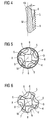
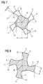
- FIG. 3 To explain the structure of the tapping tool 1, four sections VII to X are further entered in FIG. 3, the sectional views of which are illustrated in FIGS. 7 to 10.
- the sectional views VII to X can be seen on the one hand that in the case of the present embodiment in the tapping tool 1, the rake angle ⁇ P of the peripheral cutting edges 11 of the cutting edges 4 to 7, preferably continuously changed starting from the end face on the tool head 3 in the direction of the tool shank 2 ,
- the rake angle ⁇ P is approximately equal to all peripheral cutting edges 11 of the cutting edges 4 to 7 in a cross section.
- the rake angle ⁇ P which is given with respect to a circumferential cutting edge 12 and a tangent in the cutting direction S to the peripheral cutting edge 12 of one of the peripheral cutting edges 11 of the cutting edges 4 to 7, can be seen from the end face of the tool head 3, which is shown in FIG , change from + 30 ° to -5 ° at the end of a skiving gate 8.
- This last embodiment of the rake angle ⁇ P is not shown in the figures.
- a last small positive rake angle ⁇ P is entered by way of example at the circumferential cutting edge 12 of the cutting edge 5.
- the core diameter d of the tapping tool 1 increases starting from the end face of the tool head 3 in the direction of the tool shank 2. This is evident both from FIG. 7 in which the actual core diameter d and with an enlarged ßerten circle indicated the increasing core diameter d registered is to recognize and from the Figures 8 to 10 and 6, which shows a plan view of the tapping tool 1.
- each cutting edge 4 to 7 also increases, with the cutting width or tooth width Z b of each cutting edge 4 to 7 additionally increasing.
- FIG. 8 and FIG. 10 show by way of example the tooth width Z b for the cutting edge 4.
- the cross-sectional areas of the cutting edges 4 to 7 and the tooth widths Z b of the cutting edges 4 to 7 are approximately the same for all cutting edges 4 to 7 in a cross section.
- tapping tool 1 The embodiment of the tapping tool 1 described above can also be seen from the plan views, as shown in Figures 5 and 6, wherein additionally in Figure 5, the external thread of the cutting 4 to 7 is shown in the drawing, as shown in FIG 6 in comparison to FIG 5 was waived.
- the tapping tool 1 described above is particularly suitable for machining through holes of higher strength steels or for machining through holes at high speed, because of its structure.
- the resulting by the threads of the external thread of the tapping tool 1 in the processing of a through hole chips forward, d. H. deployed out of the through hole.
- For "stray" chips, so shavings that do not move forward, provided with a left twist flutes 9 are provided for the removal of the chips.
- the tapping tool can have less than four cutting edges, but also more than four cutting edges.
- the tapping tool may have three or five cutting edges.
- the cutting edges can be arranged with the same or unequal pitch around the central axis M.
- the details of the helix angle of the flutes, the peel angle bevels and the rake angle relate to the respective circumferential cutting edge of a cutting edge, wherein all cutting edges are configured substantially the same.
- the tool can also have one or more flutes with a right-handed twist, which are associated with a Schlanintroductory or those Schwarzethres, which are skewed to the right or right skew.
- Such a trained tapping tool is preferably provided for the production of left-hand threads.
- angle settings for example for the helix angle, the peel angle bevel, the peel angle tendency and / or the rake angle as described above in connection with the present embodiment are selectable within the scope of the invention.
- tapping tool need not necessarily have three such portions I to III as described above.
- the dimensioning of the tapping tool itself is selected depending on the workpieces to be machined or the through-holes to be processed.
- the thread profile angles are preferably between 50 ° and 70 ° and the thread flank angles between 25 ° and 35 °.
Landscapes
- Engineering & Computer Science (AREA)
- Mechanical Engineering (AREA)
- Milling Processes (AREA)
- Turning (AREA)
- Auxiliary Devices For Machine Tools (AREA)
Priority Applications (1)
| Application Number | Priority Date | Filing Date | Title |
|---|---|---|---|
| PL07014752T PL1902805T3 (pl) | 2006-09-19 | 2007-07-27 | Narzędzie do obróbki przedmiotu obrabianego |
Applications Claiming Priority (1)
| Application Number | Priority Date | Filing Date | Title |
|---|---|---|---|
| DE102006044575A DE102006044575A1 (de) | 2006-09-19 | 2006-09-19 | Werkzeug für die Bearbeitung eines Werkstücks |
Publications (3)
| Publication Number | Publication Date |
|---|---|
| EP1902805A2 true EP1902805A2 (fr) | 2008-03-26 |
| EP1902805A3 EP1902805A3 (fr) | 2009-10-21 |
| EP1902805B1 EP1902805B1 (fr) | 2011-03-09 |
Family
ID=38829640
Family Applications (1)
| Application Number | Title | Priority Date | Filing Date |
|---|---|---|---|
| EP07014752A Not-in-force EP1902805B1 (fr) | 2006-09-19 | 2007-07-27 | Outil pour le traitement d'une pièce à usiner |
Country Status (6)
| Country | Link |
|---|---|
| US (1) | US8272817B2 (fr) |
| EP (1) | EP1902805B1 (fr) |
| AT (1) | ATE500916T1 (fr) |
| DE (2) | DE102006044575A1 (fr) |
| ES (1) | ES2361728T3 (fr) |
| PL (1) | PL1902805T3 (fr) |
Cited By (1)
| Publication number | Priority date | Publication date | Assignee | Title |
|---|---|---|---|---|
| EP2346637A4 (fr) * | 2008-10-14 | 2013-06-05 | Kennametal Inc | Taraud et procédé pour sa fabrication |
Families Citing this family (13)
| Publication number | Priority date | Publication date | Assignee | Title |
|---|---|---|---|---|
| US8087856B2 (en) * | 2006-09-22 | 2012-01-03 | Reed Gary J | Double helix thread cutting tap |
| US7665934B2 (en) * | 2006-10-18 | 2010-02-23 | Kennametal Inc. | Cutting tap and method of making a cutting tap |
| IL211236A0 (en) * | 2011-02-15 | 2011-04-28 | Vladimir Volokh | Rotary cutter |
| WO2013132665A1 (fr) * | 2012-03-09 | 2013-09-12 | オーエスジー株式会社 | Robinet hélicoïdal |
| US20150251261A1 (en) * | 2012-07-17 | 2015-09-10 | Osg Corporation | Spiral tap |
| WO2014167984A1 (fr) * | 2013-04-08 | 2014-10-16 | 有限会社ジュコー精機 | Outil de coupe pour usiner un écrou d'un dispositif à vis coulissante, et procédé pour usiner un écrou |
| ES2675372T3 (es) * | 2014-05-20 | 2018-07-10 | Natalino Capone | Herramienta de perforación |
| US9839984B2 (en) * | 2014-08-14 | 2017-12-12 | Kennametal Inc. | Method of making a cutting tap with a correction grind |
| CN111745234A (zh) * | 2020-03-05 | 2020-10-09 | 成都新成量工具有限公司 | 一种牙宽渐增螺旋槽丝锥及其加工方法 |
| US11759914B2 (en) | 2020-08-06 | 2023-09-19 | Mate Precision Technologies Inc. | Vise assembly |
| WO2022032148A1 (fr) | 2020-08-06 | 2022-02-10 | Mate Precision Technologies Inc. | Ensemble base d'usinage |
| JP2023082310A (ja) * | 2021-12-02 | 2023-06-14 | 株式会社不二越 | タップ |
| AT528234A1 (de) * | 2024-05-02 | 2025-11-15 | Dc Swiss S A | Werkzeug zur Materialbearbeitung |
Family Cites Families (18)
| Publication number | Priority date | Publication date | Assignee | Title |
|---|---|---|---|---|
| DE416709C (de) * | 1923-07-22 | 1925-07-23 | Gustav Kuntze Dipl Ing | Gewindebohrer zum Schneiden von kegeligem Gewinde |
| US2202236A (en) * | 1938-04-27 | 1940-05-28 | Greenfield Tap & Die Corp | Tap |
| GB1090875A (en) * | 1964-08-16 | 1967-11-15 | Firth Brown Tools Ltd | Improvements in screw-cutting taps |
| US3328814A (en) * | 1964-12-07 | 1967-07-04 | Nat Twist Drill & Tool Company | Tap |
| DE2331927A1 (de) * | 1973-06-22 | 1975-01-23 | Ishihashi Seiko Higashioosaka | Werkzeug zum schneiden von innengewinde |
| DE2619517C3 (de) * | 1976-05-03 | 1981-11-05 | Emuge-Werk Richard Glimpel Fabrik für Präzisionswerkzeuge vormals Moschkau & Glimpel, 8560 Lauf | Gewindebohrer mit Schälschnitteffekt |
| DE8324835U1 (de) * | 1983-08-30 | 1983-12-08 | Wilhelm Fette Gmbh, 2053 Schwarzenbek | Gewindebohrer |
| US4708542A (en) * | 1985-04-19 | 1987-11-24 | Greenfield Industries, Inc. | Threading tap |
| JPH01171725A (ja) * | 1987-12-23 | 1989-07-06 | O S G Kk | チップカーラ付ねじれ溝タップ |
| RU2021085C1 (ru) * | 1991-06-17 | 1994-10-15 | Акционерное общество "Автонормаль" | Метчик для нарезания точных резьб |
| FR2701226B1 (fr) * | 1993-02-08 | 1996-11-22 | Rineau Freres Outillage Armor | Taraud a goujures helicouidales evolutives. |
| US5562371A (en) * | 1995-06-07 | 1996-10-08 | Lock-N-Stitch International | Tap with a non-cutting pilot |
| US6012882A (en) * | 1995-09-12 | 2000-01-11 | Turchan; Manuel C. | Combined hole making, threading, and chamfering tool with staggered thread cutting teeth |
| US5842924A (en) * | 1997-02-25 | 1998-12-01 | Manos; Mark R. | Thread repairing tool |
| JP3710360B2 (ja) * | 2000-06-12 | 2005-10-26 | オーエスジー株式会社 | スパイラルタップおよびその製造方法 |
| SE518461C2 (sv) * | 2001-02-21 | 2002-10-15 | Henrik Hansson | Benskruv, sätt för att framställa dess gängor och borr för att borra hål för detsamma |
| SE522664C2 (sv) * | 2001-04-30 | 2004-02-24 | Sandvik Ab | Skärande gängtapp och förfarande för dess tillverkning |
| US7144208B2 (en) * | 2004-06-07 | 2006-12-05 | Kennametal Inc. | Low torque tap |
-
2006
- 2006-09-19 DE DE102006044575A patent/DE102006044575A1/de not_active Withdrawn
-
2007
- 2007-07-27 DE DE502007006649T patent/DE502007006649D1/de active Active
- 2007-07-27 PL PL07014752T patent/PL1902805T3/pl unknown
- 2007-07-27 AT AT07014752T patent/ATE500916T1/de active
- 2007-07-27 ES ES07014752T patent/ES2361728T3/es active Active
- 2007-07-27 EP EP07014752A patent/EP1902805B1/fr not_active Not-in-force
- 2007-09-10 US US11/852,867 patent/US8272817B2/en active Active
Cited By (1)
| Publication number | Priority date | Publication date | Assignee | Title |
|---|---|---|---|---|
| EP2346637A4 (fr) * | 2008-10-14 | 2013-06-05 | Kennametal Inc | Taraud et procédé pour sa fabrication |
Also Published As
| Publication number | Publication date |
|---|---|
| ATE500916T1 (de) | 2011-03-15 |
| US20080069653A1 (en) | 2008-03-20 |
| DE102006044575A1 (de) | 2008-03-27 |
| ES2361728T3 (es) | 2011-06-21 |
| EP1902805B1 (fr) | 2011-03-09 |
| DE502007006649D1 (de) | 2011-04-21 |
| US8272817B2 (en) | 2012-09-25 |
| PL1902805T3 (pl) | 2011-08-31 |
| EP1902805A3 (fr) | 2009-10-21 |
Similar Documents
| Publication | Publication Date | Title |
|---|---|---|
| EP1902805B1 (fr) | Outil pour le traitement d'une pièce à usiner | |
| DE112007003489B4 (de) | Spiralgewindebohrer | |
| DE102010006796B4 (de) | Verfahren zur Herstellung eines Bohrers, sowie Bohrer | |
| DE69729467T2 (de) | Kaltformgewindebohrer mit inner diameter feinbearbeitungseinsatz und dessen herstellungsmethode | |
| DE3876820T2 (de) | Bohr- und gewindeschneidwerkzeug. | |
| DE102006026853A1 (de) | Spanabhebendes Werkzeug | |
| DE102014108219A1 (de) | Rotationswerkzeug sowie Verfahren zur Herstellung eines Rotationswerkzeugs | |
| EP2454043B1 (fr) | Foret | |
| DE69105082T2 (de) | Gewindebohrer. | |
| DE19526686B4 (de) | Mehrstufenbohrer | |
| DE102007034087B4 (de) | Fräserwerkzeug | |
| EP2848343A1 (fr) | Fraise avec cordon ayant un profilé de dent spécial | |
| DE202016106331U1 (de) | Gewindewerkzeuge mit Fluidkanälen | |
| EP1864736A2 (fr) | Outil de production de filetage doté d'une jonction de bordure | |
| DE1575120A1 (de) | Selbstschneidende Schraube | |
| DE102019135404A1 (de) | Spiralbohrer mit einer stufenstrukturierten Schneidspitze | |
| EP3722033A1 (fr) | Outil de fraisage destiné au fraisage de pièces à usiner | |
| EP2929966B1 (fr) | Outil de fraisage complet pour l'usinage rotatif de matériaux | |
| DE1953183B2 (de) | Selbstbohrende Schneidschraube | |
| DE102019218421A1 (de) | Holzbohrer | |
| WO2025181358A1 (fr) | Fraise et son utilisation | |
| DE102006032005B4 (de) | Werkzeug mit sich veränderndem Nutdrallwinkel | |
| DE112006004174T5 (de) | Spiralnut-Gewindeschneider | |
| EP2915613B1 (fr) | Foret à trou transversal | |
| DE102010025148A1 (de) | Spanabhebendes Werkzeug |
Legal Events
| Date | Code | Title | Description |
|---|---|---|---|
| PUAI | Public reference made under article 153(3) epc to a published international application that has entered the european phase |
Free format text: ORIGINAL CODE: 0009012 |
|
| AK | Designated contracting states |
Kind code of ref document: A2 Designated state(s): AT BE BG CH CY CZ DE DK EE ES FI FR GB GR HU IE IS IT LI LT LU LV MC MT NL PL PT RO SE SI SK TR |
|
| AX | Request for extension of the european patent |
Extension state: AL BA HR MK YU |
|
| PUAL | Search report despatched |
Free format text: ORIGINAL CODE: 0009013 |
|
| AK | Designated contracting states |
Kind code of ref document: A3 Designated state(s): AT BE BG CH CY CZ DE DK EE ES FI FR GB GR HU IE IS IT LI LT LU LV MC MT NL PL PT RO SE SI SK TR |
|
| AX | Request for extension of the european patent |
Extension state: AL BA HR MK RS |
|
| AKX | Designation fees paid | ||
| 17P | Request for examination filed |
Effective date: 20100421 |
|
| RBV | Designated contracting states (corrected) |
Designated state(s): AT BE BG CH CY CZ DE DK EE ES FI FR GB GR HU IE IS IT LI LT LU LV MC MT NL PL PT RO SE SI SK TR |
|
| GRAP | Despatch of communication of intention to grant a patent |
Free format text: ORIGINAL CODE: EPIDOSNIGR1 |
|
| RIC1 | Information provided on ipc code assigned before grant |
Ipc: B23G 5/06 20060101AFI20100909BHEP |
|
| GRAS | Grant fee paid |
Free format text: ORIGINAL CODE: EPIDOSNIGR3 |
|
| GRAA | (expected) grant |
Free format text: ORIGINAL CODE: 0009210 |
|
| AK | Designated contracting states |
Kind code of ref document: B1 Designated state(s): AT BE BG CH CY CZ DE DK EE ES FI FR GB GR HU IE IS IT LI LT LU LV MC MT NL PL PT RO SE SI SK TR |
|
| REG | Reference to a national code |
Ref country code: GB Ref legal event code: FG4D Free format text: NOT ENGLISH |
|
| REG | Reference to a national code |
Ref country code: CH Ref legal event code: EP |
|
| REG | Reference to a national code |
Ref country code: IE Ref legal event code: FG4D Free format text: LANGUAGE OF EP DOCUMENT: GERMAN |
|
| REF | Corresponds to: |
Ref document number: 502007006649 Country of ref document: DE Date of ref document: 20110421 Kind code of ref document: P |
|
| REG | Reference to a national code |
Ref country code: DE Ref legal event code: R096 Ref document number: 502007006649 Country of ref document: DE Effective date: 20110421 |
|
| REG | Reference to a national code |
Ref country code: CH Ref legal event code: NV Representative=s name: FIAMMENGHI-FIAMMENGHI |
|
| REG | Reference to a national code |
Ref country code: SE Ref legal event code: TRGR |
|
| REG | Reference to a national code |
Ref country code: ES Ref legal event code: FG2A Ref document number: 2361728 Country of ref document: ES Kind code of ref document: T3 Effective date: 20110621 |
|
| REG | Reference to a national code |
Ref country code: NL Ref legal event code: VDEP Effective date: 20110309 |
|
| PG25 | Lapsed in a contracting state [announced via postgrant information from national office to epo] |
Ref country code: GR Free format text: LAPSE BECAUSE OF FAILURE TO SUBMIT A TRANSLATION OF THE DESCRIPTION OR TO PAY THE FEE WITHIN THE PRESCRIBED TIME-LIMIT Effective date: 20110610 Ref country code: LT Free format text: LAPSE BECAUSE OF FAILURE TO SUBMIT A TRANSLATION OF THE DESCRIPTION OR TO PAY THE FEE WITHIN THE PRESCRIBED TIME-LIMIT Effective date: 20110309 Ref country code: LV Free format text: LAPSE BECAUSE OF FAILURE TO SUBMIT A TRANSLATION OF THE DESCRIPTION OR TO PAY THE FEE WITHIN THE PRESCRIBED TIME-LIMIT Effective date: 20110309 |
|
| LTIE | Lt: invalidation of european patent or patent extension |
Effective date: 20110309 |
|
| PG25 | Lapsed in a contracting state [announced via postgrant information from national office to epo] |
Ref country code: SI Free format text: LAPSE BECAUSE OF FAILURE TO SUBMIT A TRANSLATION OF THE DESCRIPTION OR TO PAY THE FEE WITHIN THE PRESCRIBED TIME-LIMIT Effective date: 20110309 Ref country code: CY Free format text: LAPSE BECAUSE OF FAILURE TO SUBMIT A TRANSLATION OF THE DESCRIPTION OR TO PAY THE FEE WITHIN THE PRESCRIBED TIME-LIMIT Effective date: 20110309 Ref country code: NL Free format text: LAPSE BECAUSE OF FAILURE TO SUBMIT A TRANSLATION OF THE DESCRIPTION OR TO PAY THE FEE WITHIN THE PRESCRIBED TIME-LIMIT Effective date: 20110309 Ref country code: FI Free format text: LAPSE BECAUSE OF FAILURE TO SUBMIT A TRANSLATION OF THE DESCRIPTION OR TO PAY THE FEE WITHIN THE PRESCRIBED TIME-LIMIT Effective date: 20110309 |
|
| REG | Reference to a national code |
Ref country code: PL Ref legal event code: T3 |
|
| REG | Reference to a national code |
Ref country code: IE Ref legal event code: FD4D |
|
| PG25 | Lapsed in a contracting state [announced via postgrant information from national office to epo] |
Ref country code: IE Free format text: LAPSE BECAUSE OF FAILURE TO SUBMIT A TRANSLATION OF THE DESCRIPTION OR TO PAY THE FEE WITHIN THE PRESCRIBED TIME-LIMIT Effective date: 20110309 Ref country code: PT Free format text: LAPSE BECAUSE OF FAILURE TO SUBMIT A TRANSLATION OF THE DESCRIPTION OR TO PAY THE FEE WITHIN THE PRESCRIBED TIME-LIMIT Effective date: 20110711 Ref country code: EE Free format text: LAPSE BECAUSE OF FAILURE TO SUBMIT A TRANSLATION OF THE DESCRIPTION OR TO PAY THE FEE WITHIN THE PRESCRIBED TIME-LIMIT Effective date: 20110309 |
|
| PG25 | Lapsed in a contracting state [announced via postgrant information from national office to epo] |
Ref country code: SK Free format text: LAPSE BECAUSE OF FAILURE TO SUBMIT A TRANSLATION OF THE DESCRIPTION OR TO PAY THE FEE WITHIN THE PRESCRIBED TIME-LIMIT Effective date: 20110309 Ref country code: CZ Free format text: LAPSE BECAUSE OF FAILURE TO SUBMIT A TRANSLATION OF THE DESCRIPTION OR TO PAY THE FEE WITHIN THE PRESCRIBED TIME-LIMIT Effective date: 20110309 Ref country code: RO Free format text: LAPSE BECAUSE OF FAILURE TO SUBMIT A TRANSLATION OF THE DESCRIPTION OR TO PAY THE FEE WITHIN THE PRESCRIBED TIME-LIMIT Effective date: 20110309 Ref country code: IS Free format text: LAPSE BECAUSE OF FAILURE TO SUBMIT A TRANSLATION OF THE DESCRIPTION OR TO PAY THE FEE WITHIN THE PRESCRIBED TIME-LIMIT Effective date: 20110709 |
|
| PG25 | Lapsed in a contracting state [announced via postgrant information from national office to epo] |
Ref country code: MT Free format text: LAPSE BECAUSE OF FAILURE TO SUBMIT A TRANSLATION OF THE DESCRIPTION OR TO PAY THE FEE WITHIN THE PRESCRIBED TIME-LIMIT Effective date: 20110309 |
|
| PLBE | No opposition filed within time limit |
Free format text: ORIGINAL CODE: 0009261 |
|
| STAA | Information on the status of an ep patent application or granted ep patent |
Free format text: STATUS: NO OPPOSITION FILED WITHIN TIME LIMIT |
|
| BERE | Be: lapsed |
Owner name: EMUGE-WERK RICHARD GLIMPEL G.M.B.H. & CO.KG FABRIK Effective date: 20110731 |
|
| 26N | No opposition filed |
Effective date: 20111212 |
|
| PG25 | Lapsed in a contracting state [announced via postgrant information from national office to epo] |
Ref country code: MC Free format text: LAPSE BECAUSE OF NON-PAYMENT OF DUE FEES Effective date: 20110731 Ref country code: DK Free format text: LAPSE BECAUSE OF FAILURE TO SUBMIT A TRANSLATION OF THE DESCRIPTION OR TO PAY THE FEE WITHIN THE PRESCRIBED TIME-LIMIT Effective date: 20110309 |
|
| REG | Reference to a national code |
Ref country code: DE Ref legal event code: R097 Ref document number: 502007006649 Country of ref document: DE Effective date: 20111212 |
|
| PG25 | Lapsed in a contracting state [announced via postgrant information from national office to epo] |
Ref country code: BE Free format text: LAPSE BECAUSE OF NON-PAYMENT OF DUE FEES Effective date: 20110731 |
|
| PGFP | Annual fee paid to national office [announced via postgrant information from national office to epo] |
Ref country code: GB Payment date: 20120731 Year of fee payment: 6 Ref country code: SE Payment date: 20120731 Year of fee payment: 6 |
|
| PGFP | Annual fee paid to national office [announced via postgrant information from national office to epo] |
Ref country code: PL Payment date: 20120712 Year of fee payment: 6 |
|
| PGFP | Annual fee paid to national office [announced via postgrant information from national office to epo] |
Ref country code: ES Payment date: 20120829 Year of fee payment: 6 Ref country code: FR Payment date: 20120814 Year of fee payment: 6 Ref country code: IT Payment date: 20120725 Year of fee payment: 6 |
|
| PG25 | Lapsed in a contracting state [announced via postgrant information from national office to epo] |
Ref country code: LU Free format text: LAPSE BECAUSE OF NON-PAYMENT OF DUE FEES Effective date: 20110727 |
|
| REG | Reference to a national code |
Ref country code: AT Ref legal event code: MM01 Ref document number: 500916 Country of ref document: AT Kind code of ref document: T Effective date: 20120731 |
|
| PG25 | Lapsed in a contracting state [announced via postgrant information from national office to epo] |
Ref country code: TR Free format text: LAPSE BECAUSE OF FAILURE TO SUBMIT A TRANSLATION OF THE DESCRIPTION OR TO PAY THE FEE WITHIN THE PRESCRIBED TIME-LIMIT Effective date: 20110309 |
|
| PG25 | Lapsed in a contracting state [announced via postgrant information from national office to epo] |
Ref country code: HU Free format text: LAPSE BECAUSE OF FAILURE TO SUBMIT A TRANSLATION OF THE DESCRIPTION OR TO PAY THE FEE WITHIN THE PRESCRIBED TIME-LIMIT Effective date: 20110309 Ref country code: AT Free format text: LAPSE BECAUSE OF NON-PAYMENT OF DUE FEES Effective date: 20120731 |
|
| PGFP | Annual fee paid to national office [announced via postgrant information from national office to epo] |
Ref country code: CH Payment date: 20130725 Year of fee payment: 7 |
|
| REG | Reference to a national code |
Ref country code: SE Ref legal event code: EUG |
|
| GBPC | Gb: european patent ceased through non-payment of renewal fee |
Effective date: 20130727 |
|
| REG | Reference to a national code |
Ref country code: FR Ref legal event code: ST Effective date: 20140331 |
|
| PG25 | Lapsed in a contracting state [announced via postgrant information from national office to epo] |
Ref country code: SE Free format text: LAPSE BECAUSE OF NON-PAYMENT OF DUE FEES Effective date: 20130728 Ref country code: GB Free format text: LAPSE BECAUSE OF NON-PAYMENT OF DUE FEES Effective date: 20130727 |
|
| PG25 | Lapsed in a contracting state [announced via postgrant information from national office to epo] |
Ref country code: FR Free format text: LAPSE BECAUSE OF NON-PAYMENT OF DUE FEES Effective date: 20130731 Ref country code: IT Free format text: LAPSE BECAUSE OF NON-PAYMENT OF DUE FEES Effective date: 20130727 |
|
| PG25 | Lapsed in a contracting state [announced via postgrant information from national office to epo] |
Ref country code: BG Free format text: LAPSE BECAUSE OF NON-PAYMENT OF DUE FEES Effective date: 20110309 |
|
| REG | Reference to a national code |
Ref country code: ES Ref legal event code: FD2A Effective date: 20140905 |
|
| REG | Reference to a national code |
Ref country code: PL Ref legal event code: LAPE |
|
| PG25 | Lapsed in a contracting state [announced via postgrant information from national office to epo] |
Ref country code: PL Free format text: LAPSE BECAUSE OF NON-PAYMENT OF DUE FEES Effective date: 20130727 Ref country code: ES Free format text: LAPSE BECAUSE OF NON-PAYMENT OF DUE FEES Effective date: 20130728 |
|
| REG | Reference to a national code |
Ref country code: CH Ref legal event code: PL |
|
| PG25 | Lapsed in a contracting state [announced via postgrant information from national office to epo] |
Ref country code: CH Free format text: LAPSE BECAUSE OF NON-PAYMENT OF DUE FEES Effective date: 20140731 Ref country code: LI Free format text: LAPSE BECAUSE OF NON-PAYMENT OF DUE FEES Effective date: 20140731 |
|
| PGFP | Annual fee paid to national office [announced via postgrant information from national office to epo] |
Ref country code: DE Payment date: 20240731 Year of fee payment: 18 |
|
| REG | Reference to a national code |
Ref country code: DE Ref legal event code: R119 Ref document number: 502007006649 Country of ref document: DE |
|
| PG25 | Lapsed in a contracting state [announced via postgrant information from national office to epo] |
Ref country code: DE Free format text: LAPSE BECAUSE OF NON-PAYMENT OF DUE FEES Effective date: 20260203 |